EP0037730A2 - Asymmetric ultrafiltration membrane and production thereof - Google Patents
Asymmetric ultrafiltration membrane and production thereof Download PDFInfo
- Publication number
- EP0037730A2 EP0037730A2 EP81301480A EP81301480A EP0037730A2 EP 0037730 A2 EP0037730 A2 EP 0037730A2 EP 81301480 A EP81301480 A EP 81301480A EP 81301480 A EP81301480 A EP 81301480A EP 0037730 A2 EP0037730 A2 EP 0037730A2
- Authority
- EP
- European Patent Office
- Prior art keywords
- membrane
- skin
- membranes
- polymer
- polymeric material
- Prior art date
- Legal status (The legal status is an assumption and is not a legal conclusion. Google has not performed a legal analysis and makes no representation as to the accuracy of the status listed.)
- Granted
Links
- 239000012528 membrane Substances 0.000 title claims abstract description 158
- 238000000108 ultra-filtration Methods 0.000 title claims description 11
- 238000004519 manufacturing process Methods 0.000 title description 2
- XLYOFNOQVPJJNP-UHFFFAOYSA-N water Substances O XLYOFNOQVPJJNP-UHFFFAOYSA-N 0.000 claims abstract description 40
- 230000035699 permeability Effects 0.000 claims abstract description 31
- 239000002904 solvent Substances 0.000 claims abstract description 30
- 239000007788 liquid Substances 0.000 claims abstract description 29
- 238000010791 quenching Methods 0.000 claims abstract description 26
- 230000009477 glass transition Effects 0.000 claims abstract description 25
- 239000004642 Polyimide Substances 0.000 claims abstract description 8
- 229920001721 polyimide Polymers 0.000 claims abstract description 8
- 238000005266 casting Methods 0.000 claims abstract description 7
- 238000000034 method Methods 0.000 claims description 22
- 239000000463 material Substances 0.000 claims description 20
- HEDRZPFGACZZDS-UHFFFAOYSA-N Chloroform Chemical compound ClC(Cl)Cl HEDRZPFGACZZDS-UHFFFAOYSA-N 0.000 claims description 14
- ZMXDDKWLCZADIW-UHFFFAOYSA-N N,N-Dimethylformamide Chemical compound CN(C)C=O ZMXDDKWLCZADIW-UHFFFAOYSA-N 0.000 claims description 9
- RLSSMJSEOOYNOY-UHFFFAOYSA-N m-cresol Chemical compound CC1=CC=CC(O)=C1 RLSSMJSEOOYNOY-UHFFFAOYSA-N 0.000 claims description 6
- 229940100630 metacresol Drugs 0.000 claims description 6
- 230000007423 decrease Effects 0.000 claims description 5
- 230000001376 precipitating effect Effects 0.000 claims description 4
- QTWJRLJHJPIABL-UHFFFAOYSA-N 2-methylphenol;3-methylphenol;4-methylphenol Chemical compound CC1=CC=C(O)C=C1.CC1=CC=CC(O)=C1.CC1=CC=CC=C1O QTWJRLJHJPIABL-UHFFFAOYSA-N 0.000 claims description 2
- 229920000642 polymer Polymers 0.000 abstract description 66
- 239000011148 porous material Substances 0.000 description 29
- 241000264877 Hippospongia communis Species 0.000 description 13
- 238000009792 diffusion process Methods 0.000 description 12
- 238000001878 scanning electron micrograph Methods 0.000 description 12
- KFZMGEQAYNKOFK-UHFFFAOYSA-N Isopropanol Chemical compound CC(C)O KFZMGEQAYNKOFK-UHFFFAOYSA-N 0.000 description 9
- 239000000203 mixture Substances 0.000 description 9
- 230000000717 retained effect Effects 0.000 description 9
- 238000001914 filtration Methods 0.000 description 8
- 238000001556 precipitation Methods 0.000 description 7
- LFQSCWFLJHTTHZ-UHFFFAOYSA-N Ethanol Chemical compound CCO LFQSCWFLJHTTHZ-UHFFFAOYSA-N 0.000 description 6
- 239000011521 glass Substances 0.000 description 6
- 239000002245 particle Substances 0.000 description 6
- -1 polyethylene Polymers 0.000 description 6
- 230000008569 process Effects 0.000 description 6
- 239000012530 fluid Substances 0.000 description 5
- 230000014759 maintenance of location Effects 0.000 description 5
- 230000006911 nucleation Effects 0.000 description 5
- 238000010899 nucleation Methods 0.000 description 5
- CSCPPACGZOOCGX-UHFFFAOYSA-N Acetone Chemical compound CC(C)=O CSCPPACGZOOCGX-UHFFFAOYSA-N 0.000 description 4
- 230000000737 periodic effect Effects 0.000 description 4
- 239000007787 solid Substances 0.000 description 4
- XEKOWRVHYACXOJ-UHFFFAOYSA-N Ethyl acetate Chemical compound CCOC(C)=O XEKOWRVHYACXOJ-UHFFFAOYSA-N 0.000 description 3
- 230000008901 benefit Effects 0.000 description 3
- 230000015572 biosynthetic process Effects 0.000 description 3
- 230000003287 optical effect Effects 0.000 description 3
- 230000000171 quenching effect Effects 0.000 description 3
- 230000002829 reductive effect Effects 0.000 description 3
- 239000004698 Polyethylene Substances 0.000 description 2
- 229920000292 Polyquinoline Polymers 0.000 description 2
- 239000002131 composite material Substances 0.000 description 2
- 230000007246 mechanism Effects 0.000 description 2
- 238000001471 micro-filtration Methods 0.000 description 2
- 229920003227 poly(N-vinyl carbazole) Polymers 0.000 description 2
- 229920000573 polyethylene Polymers 0.000 description 2
- 238000011045 prefiltration Methods 0.000 description 2
- 108090000623 proteins and genes Proteins 0.000 description 2
- 102000004169 proteins and genes Human genes 0.000 description 2
- 238000011144 upstream manufacturing Methods 0.000 description 2
- 125000003821 2-(trimethylsilyl)ethoxymethyl group Chemical group [H]C([H])([H])[Si](C([H])([H])[H])(C([H])([H])[H])C([H])([H])C(OC([H])([H])[*])([H])[H] 0.000 description 1
- 108010038061 Chymotrypsinogen Proteins 0.000 description 1
- 229920002307 Dextran Polymers 0.000 description 1
- FXHOOIRPVKKKFG-UHFFFAOYSA-N N,N-Dimethylacetamide Chemical compound CN(C)C(C)=O FXHOOIRPVKKKFG-UHFFFAOYSA-N 0.000 description 1
- SECXISVLQFMRJM-UHFFFAOYSA-N N-Methylpyrrolidone Chemical compound CN1CCCC1=O SECXISVLQFMRJM-UHFFFAOYSA-N 0.000 description 1
- 102000006382 Ribonucleases Human genes 0.000 description 1
- 108010083644 Ribonucleases Proteins 0.000 description 1
- 229910000831 Steel Inorganic materials 0.000 description 1
- 241000700605 Viruses Species 0.000 description 1
- 150000001298 alcohols Chemical class 0.000 description 1
- 125000001931 aliphatic group Chemical group 0.000 description 1
- 125000006615 aromatic heterocyclic group Chemical group 0.000 description 1
- 230000004888 barrier function Effects 0.000 description 1
- 230000000903 blocking effect Effects 0.000 description 1
- 230000008859 change Effects 0.000 description 1
- 230000001112 coagulating effect Effects 0.000 description 1
- 230000001427 coherent effect Effects 0.000 description 1
- 230000000052 comparative effect Effects 0.000 description 1
- 230000001143 conditioned effect Effects 0.000 description 1
- 150000001896 cresols Chemical class 0.000 description 1
- 230000001186 cumulative effect Effects 0.000 description 1
- 230000003247 decreasing effect Effects 0.000 description 1
- 238000011118 depth filtration Methods 0.000 description 1
- 238000009826 distribution Methods 0.000 description 1
- 230000000694 effects Effects 0.000 description 1
- 239000000835 fiber Substances 0.000 description 1
- 239000000706 filtrate Substances 0.000 description 1
- 239000008187 granular material Substances 0.000 description 1
- 238000007654 immersion Methods 0.000 description 1
- 229940027941 immunoglobulin g Drugs 0.000 description 1
- 230000002401 inhibitory effect Effects 0.000 description 1
- 230000003993 interaction Effects 0.000 description 1
- 230000003715 interstitial flow Effects 0.000 description 1
- 230000001788 irregular Effects 0.000 description 1
- 150000002576 ketones Chemical class 0.000 description 1
- 150000004866 oxadiazoles Chemical class 0.000 description 1
- 230000002688 persistence Effects 0.000 description 1
- 210000002381 plasma Anatomy 0.000 description 1
- 239000004014 plasticizer Substances 0.000 description 1
- 229920002492 poly(sulfone) Polymers 0.000 description 1
- 229920002480 polybenzimidazole Polymers 0.000 description 1
- 239000002244 precipitate Substances 0.000 description 1
- 230000009467 reduction Effects 0.000 description 1
- 239000013557 residual solvent Substances 0.000 description 1
- 238000004626 scanning electron microscopy Methods 0.000 description 1
- 238000000935 solvent evaporation Methods 0.000 description 1
- 239000012798 spherical particle Substances 0.000 description 1
- 230000002269 spontaneous effect Effects 0.000 description 1
- 239000010959 steel Substances 0.000 description 1
- 239000000758 substrate Substances 0.000 description 1
- 239000004753 textile Substances 0.000 description 1
Images


Classifications
-
- B—PERFORMING OPERATIONS; TRANSPORTING
- B01—PHYSICAL OR CHEMICAL PROCESSES OR APPARATUS IN GENERAL
- B01D—SEPARATION
- B01D69/00—Semi-permeable membranes for separation processes or apparatus characterised by their form, structure or properties; Manufacturing processes specially adapted therefor
- B01D69/02—Semi-permeable membranes for separation processes or apparatus characterised by their form, structure or properties; Manufacturing processes specially adapted therefor characterised by their properties
-
- B—PERFORMING OPERATIONS; TRANSPORTING
- B01—PHYSICAL OR CHEMICAL PROCESSES OR APPARATUS IN GENERAL
- B01D—SEPARATION
- B01D71/00—Semi-permeable membranes for separation processes or apparatus characterised by the material; Manufacturing processes specially adapted therefor
- B01D71/06—Organic material
- B01D71/48—Polyesters
-
- B—PERFORMING OPERATIONS; TRANSPORTING
- B01—PHYSICAL OR CHEMICAL PROCESSES OR APPARATUS IN GENERAL
- B01D—SEPARATION
- B01D71/00—Semi-permeable membranes for separation processes or apparatus characterised by the material; Manufacturing processes specially adapted therefor
- B01D71/06—Organic material
- B01D71/50—Polycarbonates
-
- B—PERFORMING OPERATIONS; TRANSPORTING
- B01—PHYSICAL OR CHEMICAL PROCESSES OR APPARATUS IN GENERAL
- B01D—SEPARATION
- B01D71/00—Semi-permeable membranes for separation processes or apparatus characterised by the material; Manufacturing processes specially adapted therefor
- B01D71/06—Organic material
- B01D71/58—Other polymers having nitrogen in the main chain, with or without oxygen or carbon only
- B01D71/62—Polycondensates having nitrogen-containing heterocyclic rings in the main chain
- B01D71/64—Polyimides; Polyamide-imides; Polyester-imides; Polyamide acids or similar polyimide precursors
Definitions
- the present invention is concerned with ultrafiltration membranes and the production thereof.
- Polymeric membranes are generally categorized according to the size of particles which they retain or according to their pore size as either ultrafiltration membranes, which have the finest pores, or microporous (microfiltration) membranes which have coarser pores.
- the dividing line between ultrafiltration membranes and microfiltration membranes is at approximately a pore size of 0.05 micrometres (this corresponds to the size of the smallest retained particle).
- Membranes may also be categorized as symmetrical, when the two faces have.similar porosity, or as asymmetric when the two faces differ in porosity.
- a membrane An important characteristic of a membrane is its permeability to water which is customarily expressed in units of cm/min-psi which represents the macroscopic velocity in cm/min at which water flows through the membrane when the driving pressure is one psi. This permeability may be measured by the volume of pure water which passes through a unit area of membrane per unit time.
- the flow of water through the membrane is, within wide limits, directly proportional to the applied pressure.
- the permeability to water decreases as the retentivity of the membrane to solutes increases, because smaller pores offer more resistance to flow.
- This relationship is not a simple one since the retentivity depends on the single smallest pore encountered by the liquid in passing the membrane, whereas the resistance to flow depends on the cumulative effect of all the pores through which the sample must pass.
- membranes of similar solute retention having uniform pores throughout their entire thickness have lower permeabilities than those whose retentivity is due to a thin skin having the same pore sizes combined with a body or substrate of much larger pores.
- symmetrical membranes offer more resistance to fluid flow and therefore have slower flow rates compared to asymmetric membranes of similar retentivity.
- membranes may be characterised by their ability to resist plugging or their dirt-holding capacity. Plugging refers to the reduction of the filtration rate during filtering as a function of the amount of liquid passing the membrane. In order to extend the lifetime of a membrane in a given filtration operation, it is customary to prefilter the fluid through a membrane or filter having higher flow rates and smaller retentivities, but still the ability to reduce severe fouling, or blocking of the final membrane filter.
- membranes vary greatly and may generally be classified as either reticulated or granular. In the former, there is a three-dimensional open network of interconnecting fibrous strands and open interstitial flow channels. In the granular type structure, however, incompletely coalesced solid particles called granules leave an interconnected network of pores between them. Reticulated membranes generally have a higher porosity than granular membranes. (The porosity of membranes is defined as "1- the relative density", or as the ratio of the weight of a given volume of membrane to that of the bulk polymer forming the membrane).
- Polymeric membranes are generally made by preparing a solution of the polymer in a suitable solvent, forming the solution into a thin sheet, a hollow tube or a hollow fibre, and then precipitating the polymer under controlled conditions. Precipitation may be carried out by solvent evaporation or by contacting the polymer solution with a non-solvent.
- U.S. Patent 3,615,024 discloses a method of forming porous polymeric membranes which are described as being highly asymmetric.
- the membranes produced according to that method are only slightly asymmetric, however, and have a permeability to water which is only slightly higher than that of symmetrical membranes of the same retentivity.
- Membranes may also be categorized as either composite, supported or integral.
- Composite membranes comprise a very thin.retentive layer attached to a preformed porous support; while in a supported membrane, the actual membrane is attached to a strong sheet material of negligible retentivity.
- Integral membranes are formed in one and the same operation and have layers of the same composition, which layers may have very different properties, depending, in general, on whether the membrane is symmetrical or asymmetric.
- an asymmetric ultrafiltration membrane having a water permeability of at least 0.2 cm/min psi, the membrane comprising an open honeycomb structure constituting the majority of the membrane and, integral therewith, a skin, the open honeycomb structure and the skin both being of a polymeric material having a glass transition temperature of at least 200°C.
- the present invention also comprises a method of producing an asymmetric ultrafiltration membrane having a water permeability of at least 0.2 cm/min psi, which comprises precipitating a membrane-forming polymeric material having a glass transition temperature of at least 200°C by casting a solution containing not more than 13% by weight of the polymeric material into a quench liquid which is a non-solvent for the polymeric material but miscible with the solvent.
- the polymeric material used to form the membrane may be any polymer which has a glass transition temperature of at least 200°C and which may form a membrane. Some polymers, due to poor strength, may not even be used to form membranes. Other polymers, such as polyethylene, lack the rigidity necessary to form honeycomb structures with thin skins. Polyethylene has a modulus of elasticity of about 10,000 psi which is insufficient; the polymeric material used in the membrane according to the invention preferably has a modulus of elasticity of at least about 100,000, typically at least about 500,000 and preferably from about one million to about five million psi. Rigid polymers generally have relatively high glass transition temperatures and moduli of elasticity.
- the glass transition temperature or "T g is that temperature at which a polymer tends to become brittle when cooled and viscoelastic when heated. It also corresponds to a change in the temperature expansion coefficient, the temperature expansion coefficient being larger above T than it is below T . Glass transition temperatures also correspond to freedom of molecular motion which is greater above T g than it is below T . Though the exact determination of the glass transition temperature depends somewhat on the method used and on the rate of the determination, it is, within 5 to 10°C, a well-accepted characteristic of a polymer. The presence of solvents or plasticizers generally lowers the glass transition temperature of a polymer so that it stays viscoelastic at temperatures at which it may be glassy when pure.
- the polymeric material for use according to the present invention must have a glass transition temperature of at least 200°C, typically at least about 250°C, and preferably from 300°C to 400°C. It has been found that polysulphones, which generally have a glass transition temperature of about 175°C, are insufficiently rigid. Polyvinyl carbazole, on the other hand, which has a glass transition temperature of 200°C, is satisfactory. Examples of polymers which are useful in the present invention are listed in the following Table I:
- Particular types of polymer useful in the present invention are polybenzimidazoles, polyquinoxalines, polyquinolines, poly-as-triazolines, poly- oxadiazoles, polyarylhydrazides, polyarylamides, and polyimides.
- Particularly preferred such polymers are polyimides because of the high flow rates which may be obtained with these polymers, because of the excellent solubility of these polymers in various solvents, and for reasons of economy and convenience: a particularly preferred polymer for reasons of convenience and economy is Ciba-Geigy XU-218 polyimide which has a glass transition temperature of between 320 and 330°C.
- Mixtures of two or more polymers may also be employed.
- heterocyclic aromatic polymers such as polyquinoxalines, polyquinolines, and poly-as- triazines, while useful in the present invention, are generally not preferred because of the fact that they are costly and difficult to obtain.
- a solvent which may be any liquid which dissolves the polymer and is miscible with the quench liquid as described below.
- a solvent which may be any liquid which dissolves the polymer and is miscible with the quench liquid as described below.
- the particular solvent chosen will, of course, depend upon the particular polymer and quench liquid used, but an appropriate choice of solvent for each particular polymer/solvent/quench liquid system will be clear to those skilled in this art.
- Suitable solvents include cresols, such as meta-cresol, chloroform, mixtures of chloroform and meta-cresol, dimethylformamide, dimethylacetamide and N-methylpyrrolidone. Mixtures of two or more solvents may also be employed.
- the solvent must be such as to produce a stable solution but the stability of the solution must be such that it is destroyed by the addition of a relatively small amount of a miscible non-solvent quench liquid such as isopropyl alcohol or acetone.
- a miscible non-solvent quench liquid such as isopropyl alcohol or acetone.
- the amount of miscible non-solvent which may be added to destroy the stability of the polymer solution is preferably less than 10, typically less than about 7, and preferably less than about 5% by weight of the casting dope.
- the concentration of polymer in the solvent should be low, much lower than that used in conventional casting processes and is less than 13% by weight.
- the preferred concentration will depend on the nature of the polymer but the concentration is generally less than 10%, more preferably from 3 to 7% by weight of the solution.
- the polymer solutions when quenched, form granular structures rather than the honeycombed structures of the present invention prepared by these nucleation and growth processes.
- the quench liquid may be any liquid which is a non-solvent for the polymer and which is miscible with the solvent, and which is such that when the solvent described above contacts the quench liquid, the polymer substantially immediately precipitates as a solid membrane.
- quench liquids which may be used for a particular polymer/solvent/quench liquid system vary depending upon the system but an appropriate choice of such a quench liquid will be clear to those skilled in this art.
- Suitable quench liquids include water, lower alcohols such as isopropyl alcohol, lower ketones such as acetone, and lower aliphatic esters such as ethyl acetate. Water is a particularly preferred quench liquid for reasons of economy and convenience. Mixtures of two or more quench liquids may also be used.
- the method according to the invention may be carried out in a continuous, semi-continuous or batch method, as desired, and at any suitable temperature, but substantially ambient temperatures are preferred. This process may also be carried out at atmospheric, sub-atmospheric, or super atmospheric pressures, although substantially atmospheric pressures are preferred.
- the membranes formed by the method according to the invention are asymmetric ultrafiltration membranes.
- the pores of the skin of these ultrafiltration membranes are substantially uniform in size and are generally from 0.5 to 50, typically from 1 to 30, most preferably from 3 to 20 millimicrons in diameter.
- the membranes of the present invention have a water permeability of at least about 0.2 cm/min psi, preferably at least about 0.4 cm/min psi, more preferably from about 0.4 to about 1.0 cm/min psi.
- Water permeability depends, of course, on pore size; with membranes which have a molecular weight cut-off of about 10,000, the water permeability may be from 0.2 to 0.5 cm/min psi, while with membranes which have a molecular weight cut-off of about 100,000, the water permeability may be from 2 to 3 cm/min psi. With membranes which have molecular weight cut-off of about one million, the water permeability may be from 5 to 8 cm/min psi.
- membranes of this invention are particularly advantageous in that they have a high water permeability relative to their retentivity.
- membranes of the present invention which have a molecular weight cut-off of 10,000, i.e., those membranes which will retain molecules which have a molecular weight greater than or equal to 10,000 while allowing smaller molecules .to pass through, have typically a water permeability of 0.5 cm/min psi. This is about 20 times higher than the best commercially available ultrafilters having the same molecular weight cut-off.
- this relationship between water permeability and molecular weight cut-off is by the ratio of the water permeability (expressed in cm/min psi) to the molecular weight cut-off.
- this ratio is generally greater than 0.4 x 10- 5 , typically greater than 2 x 10- 5 , more preferably from 2 x 10 -5 to 3 x 10 -5 cm/min psi.
- Another way of expressing the relationship between water permeability and molecular weight cut-off is by the ratio of the water permeability (expressed in cm/min psi) to the square root of the molecular weight cut-off.
- this ratio is generally greater than 2 x 10 -3 , typically greater than 4 x 10 -3 , more preferably from 5 x 10 -3 to 9 x 10 -3 cm/min psi.
- the membranes according to the present invention have very high water permaabilities combined with excellent retention properties as ultrafilters, i.e., these membranes are capable of retaining proteins, viruses and the like.
- This combination of properties is related to a novel structure which comprises an extremely thin skin (see Figure 6) and a tubular or honeycombed supporting structure (see Figures 3 and 4) forming the majority of the membrane. Because of its uniform pore size, the skin offers excellent retention properties, and because it is very thin, the skin offers little resistance to liquid flow.
- the open honeycomb structure of the remainder of the membrane provides open passageways for the water as well as support for the skin.
- the skin of the membranes of the present invention do not have the substantially circular pores characteristic of prior art membranes (compare Figures 1 and 2). Instead, the surface is formed by irregularly shaped approximately isometric compact areas, which are approximately tens of Angstrom units in size. These irregularly shaped areas are closely packed together leaving slit-like fissures or elongated channels between them, these slit-like fissures being apparently interconnected forming an irregular network.
- the supporting part of the membrane appears in cross-section as large regular columns substantially normal to the skin.
- This supporting structure is illustrated in Figure 3 which shows a cross-section of the membrane of the present invention with a regular tubular structure with a tube diameter of about 10 millimicrons extending throughout the cross-section from the bottom of the membrane to near the skin. These channels may become larger away from the skin either as the columns become thinner or, more frequently, as the number of columns become smaller.
- Figure 4 which shows a membrane according to the present invention in cross-section illustrating the periodic increase in tubular hollow columns from the skin to the bottom of the membrane. Four periods in column channels are apparent in Figure 4.
- the columnar structure extends over generally at least 90, typically at least 95, and preferably at least 98% of the membrane thickness and over substantially all the membrane width and depth as illustrated in Figure 3.
- the bottom of the membrane i.e., the face opposite the skin, generally comprises a highly porous very thin layer of fibres.
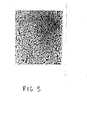
- Figure 5 an SEM photograph of the bottom surface of a membrane of the present invention (magnified 2,000 times), shows the fibrillar network structure of the bottom layer. These fibres are formed under very different conditions from the bulk of the membrane because of the presence of the support (such as glass or steel or appropriate textile or paper material) upon which the membrane is cast.
- One particular advantage of the membranes according to the invention is that the skin is well supported by the fine structure near it (see Figure 6) but the flow of filtrate suffers minimum impediment because the channels enlarge rapidly and especially because they are straight and unobstructed except by the porous bottom layer which offers very little resistance.
- honeycomb structure of the membranes of the present invention is believed to result from the local interaction on the one hand of supersaturation produced by diffusion of the quenching fluid into the polymer solution and, on the other hand, from the depletion of polymer by its diffusion and precipitation on previously precipitated polymer acting as a nucleus.
- the two processes occur at the proper rates and the supersaturation progresses as a front parallel to the membrane surface, the columnar structure may be formed.
- Precipitation and relieving of the supersaturation require diffusion of the polymer toward the site of precipitation. This diffusion occurs at approximately a constant rate whether close to the skin or away from it. As the solution becomes more rapidly supersaturated near the skin, the distance over which it may be relieved by diffusion is small and growth occurs at closely spaced points. Further away from the skin, solubility decreases more slowly because of diffusion of quench liquid over greater distances in relieving the resulting supersaturation and growth occurs at more widely spaced centres.
- solubility decreases progressively further away from the skin as time passes means that supersaturation tends to occur always in the region just beyond the already precipitated polymer and thus tends to extend the growth in the direction away from the skin.
- growth occurs so as to increase the length of the tubes and not to increase their width or diameter. Uniformity of growth is conditioned by the uniformity of the skin.
- the thickness of the membrane as cast is some four to five times greater than that of the membranes after quenching.
- diffusion of solvent across the skin and into the quench liquid must proceed faster than that of quench liquid in the opposite direction.
- the porosity of the membrane is, however, greater away from the skin than near it. This suggests that the difference in diffusion rates is larger at the beginning than towards the end of the precipitation process.
- the polymer becomes precipitated from a more concentrated solution - one from which more solvent has diffused out - in the early stages near the skin, than later near the other face of the membrane.
- nucleation i.e., the spontaneous beginning of new precipitation
- the polymer away from the growing tip of the tube would be expected to precipitate at its original location instead of diffusing to the tip before precipitating.
- this nucleation is inhibited more in more concentrated polymer solutions so that these tend to form larger tubes and fewer terminations of growth than more dilute solutions.
- Polymer solutions above a certain concentration no longer produce honeycomb structures but produce instead conventional granular or reticulated structures.
- the desirable properties of the membranes of this invention depend upon the rigidity of the polymer as soon as it is precipitated.
- the persistence of the very narrow elongated pores between tiny globules of polymer require that these pores do not tend to coalesce or fuse.
- the skin should also provide a highly uniform barrier (see Figures 2 and 6) to the rapid mixing of solvent and quench liquid, allowing only regular and uniform diffusion required for the formation of honeycomb structures.
- the fact that these structures are observed only with polymers having relatively very high glass transition temperatures (greater than 200 o C) is believed to be related to the rigidity of the polymer as precipitated.
- the polymer is necessarily somewhat swollen by and plasticized by the residual solvent in it, its glass transition temperature is not lowered sufficiently to destroy the desirable role of the skin during quenching. If the glass transition temperature of the polymer is too low, this effect is lost and membranes according to the invention are not produced.
- precipitation proceeds directly to a solid or glass without going through a gel state as happens with polymers having lower glass transition temperatures.
- Ciba-Geigy XU 218 polyimide (having a glass transition temperature between 320 0 and 330 0 C) was dissolved in dimethylformamide to form a 7% polymer solution, the solution being cast onto a glass plate to a uniform wet thickness of 500 microns by means of a doctor blade at a constant withdrawal rate of 30 feet/minute.
- the wet film was drawn immediately into a water bath at room temperature. Within a few seconds after immersion a pale yellow - p paque film formed which was allowed to remain in the bath for an additional two minutes.
- the thus-formed membrane had a thickness of 170 microns, a water permeability of 2 cm/min psi and a nominal molecular weight cut-off of 25,000 for globular solutes (i.e. proteins).
- the membrane had a tensile strength of 380 psi. Examination under an optical microscope at a magnification of 100 indicated that the cross-section of this membrane had an open honeycomb structure of regular columns having a diameter of from 3 to 5 microns.
- Example I The polyimide of Example I was dissolved in a mixture of 50% meta-cresol and 50% chloroform to obtain a final solid content of 4.5% by weight polymer.
- a membrane was prepared from this solution as in Example I except that isopropyl alcohol was used in the coagulating bath in place of water. After one minute residence time in the alcohol bath, the membrane was stripped from the glass plate and stored in alcohol.
- the water permeability of the membrane was 5 cm/min psi, its tensile strength was 185 psi, and it had a molecular weight cut-off of about 100,000.
- the SEM of the surface skin (magnified 100,000 times) of this membrane is shown in Figure 1, a cross-section of this membrane, magnified 1,000 times, is shown in Figure 4, and the bottom surface of this membrane, magnified 2,000 times, is shown in Figure 5.
- Figure 4 illustrates the periodic increase in tubular hollow columns from the skin to the bottom of the membrane thickness.
- Figure 6 is an SEM of a cross-section of this membrane, magnified 5,000 times, illustrating the sharp boundary between the skin (top), having a thickness of about 100 A o , and the substructure. This membrane retained 99.8% immunoglobulin G (which has a molecular weight of 160,000).
- Polyvinyl carbazole (which is commercially available from the Aldrich Chemical Co.), having a glass transition temperature of 200 o C, was dissolved in a mixture of 50% meta-cresol and 50% chloroform to form a 6% by weight polymer solution. This solution was then cast as in Example I but using an ethanol bath to form a membrane which had a water permeability of 2 cm/min psi, a molecular weight cut-off of 50,000, and a tensile strength of 240 psi.
- Figure 3 is an SEM of a cross-section of this membrane magnified 1,000 times illustrating the tubular structure of the support of this membrane.
- the membrane produced by this process had a water permeability of 0.5 cm/min psi, a molecular weight cut-off of 10,000, and a tensile strength of 600 psi. Examination under.an optical microscope showed that it had a cross-section consisting of a honeycomb structure with regular columns.
- Poly(2, 2'-octamethylene-5, 5'-dibenzimidazole) was prepared according to the method disclosed at pages l03 and 104 of the 1968 edition of Polymer Chemistry (Interscience Publishers). This polymer had a polymer melt temperature (which is, within experimental error, approximately equal to the glass transition temperature) of 250 o C. The polymer was dissolved in a mixture of 50% meta-cresol and 50% chloroform to form a 3% by weight polymer solution. This solution was cast to form a membrane according to the procedure of Example II.
- the membrane had a water permeability of 8 cm/min psi, completely retained the solute Dextran blue 2000, and had a molecular weight cut-off of 2 x 10 6 . Examination of cross-sections of this membrane under an optical microscope show a honeycomb structure of regular columns.
- Table II illustrates the differences in water permeability (in cm/min psi) between ultrafilters of the prior art and those of the present invention.
- An advantage of the membranes of the present invention is that their water permeability is not so drastically reduced by the presence of retained particles (solutes) as that of prior art membranes.
- a 25,000 molecular weight cut-off membrane such as that described in the above Example I has its water permeability reduced by a factor of only five (i.e. from about 2 cm/min psi to about 0.4 cm/min psi) during filtration of a 0.1% solution of a-chymotrypsinogen.
- Presently commercially available membranes on the other hand, not only have a lower initial filtration rate but this initial filtration rate is reduced by an order of magnitude more during filtration.
- Figures 1 and 2 are SEMs of the surface skin of a membrane of the present invention (Figure 1) and a membrane of the prior art ( Figure 2) at the same magnification.
- Figure 1 illustrates that the skin of the membranes of the present invention has interconnecting channels or pores which are about 50A o in width and about 100 to 500A° in length with domain structure of polymer molecules inbetween.
- Figure 2 illustrates that the skin of the membranes of the prior art has substantially circular pore structure with a wide distribution of pore size ranging from about 100 to 500A o in diameter.
- the membranes of the present invention are advantageous due to the sharpness of their molecular weight cut-off.
- the membrane prepared according to the above Example I rejects only 10% of ribonuclease (having a molecular weight of 17,000) but rejects 98% of ⁇ -chymotrypsinogen (having a molecular weight of 22,000). This sharpness of molecular weight cut-off is believed to be related to the uniformity of the pore sizes formed in the skin of these membranes.
- the membranes of this invention may be used with either the skin side or the support side of the membrane upstream with respect to fluid flow.
- certain "dirty" solutions such as blood plasma
- the support serves as a built-in prefilter, greatly increasing the dirt-holding capacity of the membrane.
- the fluid encounters the larger channels first and later encounters channels having gradually decreasing size with the very small pores - those in the skin - being encountered last. Hence larger particles are retained before they reach the skin and do not clog its pores.
- An in-depth filtration is obtained in which the particles are retained at various levels leaving many more channels and pores available for flow than if they were all retained in one plane at the skin. If the membrane is not highly asymmetrical this advantage does not occur since approximately the same amount of retained matter fouls both sides of the membrane because the pore sizes on both sides would be approximately the same.
Abstract
Description
- The present invention is concerned with ultrafiltration membranes and the production thereof.
- Polymeric membranes are generally categorized according to the size of particles which they retain or according to their pore size as either ultrafiltration membranes, which have the finest pores, or microporous (microfiltration) membranes which have coarser pores. The dividing line between ultrafiltration membranes and microfiltration membranes is at approximately a pore size of 0.05 micrometres (this corresponds to the size of the smallest retained particle).
- Membranes may also be categorized as symmetrical, when the two faces have.similar porosity, or as asymmetric when the two faces differ in porosity.
- An important characteristic of a membrane is its permeability to water which is customarily expressed in units of cm/min-psi which represents the macroscopic velocity in cm/min at which water flows through the membrane when the driving pressure is one psi. This permeability may be measured by the volume of pure water which passes through a unit area of membrane per unit time.
- The flow of water through the membrane is, within wide limits, directly proportional to the applied pressure. In general, the permeability to water decreases as the retentivity of the membrane to solutes increases, because smaller pores offer more resistance to flow. This relationship, however, is not a simple one since the retentivity depends on the single smallest pore encountered by the liquid in passing the membrane, whereas the resistance to flow depends on the cumulative effect of all the pores through which the sample must pass. Hence, membranes of similar solute retention having uniform pores throughout their entire thickness have lower permeabilities than those whose retentivity is due to a thin skin having the same pore sizes combined with a body or substrate of much larger pores. In other words, symmetrical membranes offer more resistance to fluid flow and therefore have slower flow rates compared to asymmetric membranes of similar retentivity.
- In addition to their retention characteristics, membranes may be characterised by their ability to resist plugging or their dirt-holding capacity. Plugging refers to the reduction of the filtration rate during filtering as a function of the amount of liquid passing the membrane. In order to extend the lifetime of a membrane in a given filtration operation, it is customary to prefilter the fluid through a membrane or filter having higher flow rates and smaller retentivities, but still the ability to reduce severe fouling, or blocking of the final membrane filter.
- Structurally, membranes vary greatly and may generally be classified as either reticulated or granular. In the former, there is a three-dimensional open network of interconnecting fibrous strands and open interstitial flow channels. In the granular type structure, however, incompletely coalesced solid particles called granules leave an interconnected network of pores between them. Reticulated membranes generally have a higher porosity than granular membranes. (The porosity of membranes is defined as "1- the relative density", or as the ratio of the weight of a given volume of membrane to that of the bulk polymer forming the membrane).
- Polymeric membranes are generally made by preparing a solution of the polymer in a suitable solvent, forming the solution into a thin sheet, a hollow tube or a hollow fibre, and then precipitating the polymer under controlled conditions. Precipitation may be carried out by solvent evaporation or by contacting the polymer solution with a non-solvent.
- U.S. Patent 3,615,024 discloses a method of forming porous polymeric membranes which are described as being highly asymmetric. The membranes produced according to that method are only slightly asymmetric, however, and have a permeability to water which is only slightly higher than that of symmetrical membranes of the same retentivity.
- Membranes may also be categorized as either composite, supported or integral. Composite membranes comprise a very thin.retentive layer attached to a preformed porous support; while in a supported membrane, the actual membrane is attached to a strong sheet material of negligible retentivity. Integral membranes are formed in one and the same operation and have layers of the same composition, which layers may have very different properties, depending, in general, on whether the membrane is symmetrical or asymmetric.
- There is a continual demand for improved, highly asymmetric, integral ultrafiltration membranes having improved retention properties and enhanced flow rates; according to the invention, therefore, there is provided an asymmetric ultrafiltration membrane having a water permeability of at least 0.2 cm/min psi, the membrane comprising an open honeycomb structure constituting the majority of the membrane and, integral therewith, a skin, the open honeycomb structure and the skin both being of a polymeric material having a glass transition temperature of at least 200°C.
- The present invention also comprises a method of producing an asymmetric ultrafiltration membrane having a water permeability of at least 0.2 cm/min psi, which comprises precipitating a membrane-forming polymeric material having a glass transition temperature of at least 200°C by casting a solution containing not more than 13% by weight of the polymeric material into a quench liquid which is a non-solvent for the polymeric material but miscible with the solvent.
- The polymeric material used to form the membrane may be any polymer which has a glass transition temperature of at least 200°C and which may form a membrane. Some polymers, due to poor strength, may not even be used to form membranes. Other polymers, such as polyethylene, lack the rigidity necessary to form honeycomb structures with thin skins. Polyethylene has a modulus of elasticity of about 10,000 psi which is insufficient; the polymeric material used in the membrane according to the invention preferably has a modulus of elasticity of at least about 100,000, typically at least about 500,000 and preferably from about one million to about five million psi. Rigid polymers generally have relatively high glass transition temperatures and moduli of elasticity.
- The glass transition temperature or "T g is that temperature at which a polymer tends to become brittle when cooled and viscoelastic when heated. It also corresponds to a change in the temperature expansion coefficient, the temperature expansion coefficient being larger above T than it is below T . Glass transition temperatures also correspond to freedom of molecular motion which is greater above T g than it is below T . Though the exact determination of the glass transition temperature depends somewhat on the method used and on the rate of the determination, it is, within 5 to 10°C, a well-accepted characteristic of a polymer. The presence of solvents or plasticizers generally lowers the glass transition temperature of a polymer so that it stays viscoelastic at temperatures at which it may be glassy when pure.
- The polymeric material for use according to the present invention must have a glass transition temperature of at least 200°C, typically at least about 250°C, and preferably from 300°C to 400°C. It has been found that polysulphones, which generally have a glass transition temperature of about 175°C, are insufficiently rigid. Polyvinyl carbazole, on the other hand, which has a glass transition temperature of 200°C, is satisfactory. Examples of polymers which are useful in the present invention are listed in the following Table I:

- Particular types of polymer useful in the present invention are polybenzimidazoles, polyquinoxalines, polyquinolines, poly-as-triazolines, poly- oxadiazoles, polyarylhydrazides, polyarylamides, and polyimides. Particularly preferred such polymers are polyimides because of the high flow rates which may be obtained with these polymers, because of the excellent solubility of these polymers in various solvents, and for reasons of economy and convenience: a particularly preferred polymer for reasons of convenience and economy is Ciba-Geigy XU-218 polyimide which has a glass transition temperature of between 320 and 330°C.
- Mixtures of two or more polymers may also be employed.
- Six membered heterocyclic aromatic polymers such as polyquinoxalines, polyquinolines, and poly-as- triazines, while useful in the present invention, are generally not preferred because of the fact that they are costly and difficult to obtain.
- In order to produce a membrane in the method according to the invention, the polymeric material is dissolved in a solvent, which may be any liquid which dissolves the polymer and is miscible with the quench liquid as described below. The particular solvent chosen will, of course, depend upon the particular polymer and quench liquid used, but an appropriate choice of solvent for each particular polymer/solvent/quench liquid system will be clear to those skilled in this art. Suitable solvents include cresols, such as meta-cresol, chloroform, mixtures of chloroform and meta-cresol, dimethylformamide, dimethylacetamide and N-methylpyrrolidone. Mixtures of two or more solvents may also be employed.
- The solvent must be such as to produce a stable solution but the stability of the solution must be such that it is destroyed by the addition of a relatively small amount of a miscible non-solvent quench liquid such as isopropyl alcohol or acetone. The amount of miscible non-solvent which may be added to destroy the stability of the polymer solution is preferably less than 10, typically less than about 7, and preferably less than about 5% by weight of the casting dope.
- The concentration of polymer in the solvent should be low, much lower than that used in conventional casting processes and is less than 13% by weight. The preferred concentration will depend on the nature of the polymer but the concentration is generally less than 10%, more preferably from 3 to 7% by weight of the solution. At polymer concentrations substantially in excess of 13% by weight, the polymer solutions, when quenched, form granular structures rather than the honeycombed structures of the present invention prepared by these nucleation and growth processes. At polymer concentrations substantially less than 3% by weight, there may be insufficient polymer available to form a coherent membrane.
- The quench liquid may be any liquid which is a non-solvent for the polymer and which is miscible with the solvent, and which is such that when the solvent described above contacts the quench liquid, the polymer substantially immediately precipitates as a solid membrane.
- Particular quench liquids which may be used for a particular polymer/solvent/quench liquid system vary depending upon the system but an appropriate choice of such a quench liquid will be clear to those skilled in this art. Suitable quench liquids include water, lower alcohols such as isopropyl alcohol, lower ketones such as acetone, and lower aliphatic esters such as ethyl acetate. Water is a particularly preferred quench liquid for reasons of economy and convenience. Mixtures of two or more quench liquids may also be used.
- The method according to the invention may be carried out in a continuous, semi-continuous or batch method, as desired, and at any suitable temperature, but substantially ambient temperatures are preferred. This process may also be carried out at atmospheric, sub-atmospheric, or super atmospheric pressures, although substantially atmospheric pressures are preferred.
- The membranes formed by the method according to the invention are asymmetric ultrafiltration membranes. The pores of the skin of these ultrafiltration membranes are substantially uniform in size and are generally from 0.5 to 50, typically from 1 to 30, most preferably from 3 to 20 millimicrons in diameter.
- The membranes of the present invention have a water permeability of at least about 0.2 cm/min psi, preferably at least about 0.4 cm/min psi, more preferably from about 0.4 to about 1.0 cm/min psi. Water permeability depends, of course, on pore size; with membranes which have a molecular weight cut-off of about 10,000, the water permeability may be from 0.2 to 0.5 cm/min psi, while with membranes which have a molecular weight cut-off of about 100,000, the water permeability may be from 2 to 3 cm/min psi. With membranes which have molecular weight cut-off of about one million, the water permeability may be from 5 to 8 cm/min psi.
- The membranes of this invention are particularly advantageous in that they have a high water permeability relative to their retentivity. Thus, membranes of the present invention which have a molecular weight cut-off of 10,000, i.e., those membranes which will retain molecules which have a molecular weight greater than or equal to 10,000 while allowing smaller molecules .to pass through, have typically a water permeability of 0.5 cm/min psi. This is about 20 times higher than the best commercially available ultrafilters having the same molecular weight cut-off.
- One way of expressing this relationship between water permeability and molecular weight cut-off is by the ratio of the water permeability (expressed in cm/min psi) to the molecular weight cut-off. For membranes of the present invention, this ratio is generally greater than 0.4 x 10⁻⁵, typically greater than 2 x 10⁻⁵, more preferably from 2 x 10⁻⁵ to 3 x 10⁻⁵ cm/min psi.
- Another way of expressing the relationship between water permeability and molecular weight cut-off is by the ratio of the water permeability (expressed in cm/min psi) to the square root of the molecular weight cut-off. For membranes of the present invention, this ratio is generally greater than 2 x 10⁻³, typically greater than 4 x 10⁻³, more preferably from 5 x 10⁻³ to 9 x 10⁻³ cm/min psi.
- In the following description, reference will be made to the accompanying drawings, in which:
- Figure 1 is a Scanning Electron Micrograph (SEM) of the surface skin of a membrane according to the invention magnified 100,000 times;
- Figure 2 is an SEM of the surface skin of a prior art membrane magnified 100,000 times;
- Figure 3 is an SEM of a cross-section of a membrane according to the present invention magnified 1,000 times; this Figure illustrates the tubular structure of the honeycomb structure of the membrane;
- Figure 4 is an SEM of a cross-section of a membrane according to the present invention magnified 1,000 times and illustrates the periodic increase in tubular hollow columns with distance from the skin;
- Figure 5 is an SEM of the bottom surface of a membrane according to the present invention magnified 2,000 times;
- Figure 6 is an SEM of a cross-section of a membrane according to the present invention magnified 5,000 times illustrating the sharp boundary between the skin (top) having a thickness of about 100A0 and the substructure;
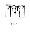
- Figure 7 is a simulated model of the nucleation and growth structure of membranes according to the present invention.
- Figures 1, 4, 5 and 6 relate to the membrane produced according to Example II; and Figure 3 relates to the membrane produced according to Example III, as will be described in more detail hereinafter.
- The membranes according to the present invention have very high water permaabilities combined with excellent retention properties as ultrafilters, i.e., these membranes are capable of retaining proteins, viruses and the like. This combination of properties is related to a novel structure which comprises an extremely thin skin (see Figure 6) and a tubular or honeycombed supporting structure (see Figures 3 and 4) forming the majority of the membrane. Because of its uniform pore size, the skin offers excellent retention properties, and because it is very thin, the skin offers little resistance to liquid flow. The open honeycomb structure of the remainder of the membrane provides open passageways for the water as well as support for the skin.
- The skin of the membranes of the present invention do not have the substantially circular pores characteristic of prior art membranes (compare Figures 1 and 2). Instead, the surface is formed by irregularly shaped approximately isometric compact areas, which are approximately tens of Angstrom units in size. These irregularly shaped areas are closely packed together leaving slit-like fissures or elongated channels between them, these slit-like fissures being apparently interconnected forming an irregular network.
- Although we do not wish to be bound by any particular theory, it is believed that these compact areas may be individual polymer molecules or aggregates of a few of them and that the fissures between them represent the pores through which the liquid passes. An SEM photograph (magnified 100,000 times) of the surface skin of a membrane of the present invention is shown in Figure 1 and a similar photograph of the skin of a conventional membrane is shown in Figure 2 to illustrate this structural difference.
- The supporting part of the membrane appears in cross-section as large regular columns substantially normal to the skin. This supporting structure is illustrated in Figure 3 which shows a cross-section of the membrane of the present invention with a regular tubular structure with a tube diameter of about 10 millimicrons extending throughout the cross-section from the bottom of the membrane to near the skin. These channels may become larger away from the skin either as the columns become thinner or, more frequently, as the number of columns become smaller. In this connection see Figure 4 which shows a membrane according to the present invention in cross-section illustrating the periodic increase in tubular hollow columns from the skin to the bottom of the membrane. Four periods in column channels are apparent in Figure 4.
- When the channels become larger away from the skin as the number of columns become smaller, some of the columns terminate at a certain distance from the skin and others continue. The distance from the skin at which these terminations occur is quite uniform along the membrane and the termination (i.e. the end of a period ) may be repeated several times so>that a periodic structure may be formed (see Figure 4). The number of levels at which some columns terminate tends to increase as the casting solution becomes more dilute.
- Between the skin and the columnar region there may be a very thin layer which is difficult to examine microscopically and which may be granular in structure but the columnar structure extends over generally at least 90, typically at least 95, and preferably at least 98% of the membrane thickness and over substantially all the membrane width and depth as illustrated in Figure 3.
- The columns described above appear on membrane cross-sections when examined microscopically. As this is a two-dimensional view, it is clear that these columns are cross-sectional views of tubular structures extending essentially normally to the membrane surface and increasing in diameter away from the skin (see Figure 4). These tubes are closely and regularly packed so that a cross-section parallel to the skin shows close packed polygons, mainly hexagons with occasional pentagons or heptagons. Thus the novel structure of the membranes of this invention may be considered as honeycombed either as a single honeycomb whose wall thickness decreases away from the skin and/ or as a series of honeycombs of gradually increasing mesh size away from the skin.
- The bottom of the membrane, i.e., the face opposite the skin, generally comprises a highly porous very thin layer of fibres. Figure 5, an SEM photograph of the bottom surface of a membrane of the present invention (magnified 2,000 times), shows the fibrillar network structure of the bottom layer. These fibres are formed under very different conditions from the bulk of the membrane because of the presence of the support (such as glass or steel or appropriate textile or paper material) upon which the membrane is cast.
- One particular advantage of the membranes according to the invention is that the skin is well supported by the fine structure near it (see Figure 6) but the flow of filtrate suffers minimum impediment because the channels enlarge rapidly and especially because they are straight and unobstructed except by the porous bottom layer which offers very little resistance.
- Again, although we do not wish to be bound by any particular theory, the honeycomb structure of the membranes of the present invention is believed to result from the local interaction on the one hand of supersaturation produced by diffusion of the quenching fluid into the polymer solution and, on the other hand, from the depletion of polymer by its diffusion and precipitation on previously precipitated polymer acting as a nucleus. When the two processes occur at the proper rates and the supersaturation progresses as a front parallel to the membrane surface, the columnar structure may be formed.
- Column formation is believed to take place by the following mechanism. When the casting dope is first contacted with the quench liquid, the polymer is precipitated as a thin skin through which diffusion of the solvent and quench liquid must take place. This diffusion is initially very rapid as the concentration gradient is very high and then becomes gradually slower as the region of concentration gradient expands. Thus the system becomes supersaturated in polymer first near the skin and then gradually further and further away from it. Supersaturation causes the formation of a large number of nuclei and their growth which depletes the polymer in the surrounding solution, thus relieving the supersaturation and inhibiting further growth. This process occurs progressively at successive layers from the skin to the other face of the membrane. This proposed mechanism would result in "nucleation and growth" of the model structure illustrated in Figure 7.
- Precipitation and relieving of the supersaturation require diffusion of the polymer toward the site of precipitation. This diffusion occurs at approximately a constant rate whether close to the skin or away from it. As the solution becomes more rapidly supersaturated near the skin, the distance over which it may be relieved by diffusion is small and growth occurs at closely spaced points. Further away from the skin, solubility decreases more slowly because of diffusion of quench liquid over greater distances in relieving the resulting supersaturation and growth occurs at more widely spaced centres.
- Thus, some of the tubes become starved in polymer and cease to grow whereas others continue and are then fed by a larger volume of the solution. As the mutual diffusion of solvent and quench liquid becomes slower with time and distance from the skin, the number of growing tubes becomes smaller.
- The fact that solubility decreases progressively further away from the skin as time passes means that supersaturation tends to occur always in the region just beyond the already precipitated polymer and thus tends to extend the growth in the direction away from the skin. Thus growth occurs so as to increase the length of the tubes and not to increase their width or diameter. Uniformity of growth is conditioned by the uniformity of the skin.
- The thickness of the membrane as cast is some four to five times greater than that of the membranes after quenching. Thus, diffusion of solvent across the skin and into the quench liquid must proceed faster than that of quench liquid in the opposite direction. The porosity of the membrane is, however, greater away from the skin than near it. This suggests that the difference in diffusion rates is larger at the beginning than towards the end of the precipitation process. Thus, the polymer becomes precipitated from a more concentrated solution - one from which more solvent has diffused out - in the early stages near the skin, than later near the other face of the membrane.
- In order to obtain the compact structure of the membrane of the present invention it appears that nucleation, i.e., the spontaneous beginning of new precipitation, must be relatively limited. Otherwise the polymer away from the growing tip of the tube would be expected to precipitate at its original location instead of diffusing to the tip before precipitating. Furthermore, it seems that this nucleation is inhibited more in more concentrated polymer solutions so that these tend to form larger tubes and fewer terminations of growth than more dilute solutions. Polymer solutions above a certain concentration, however, no longer produce honeycomb structures but produce instead conventional granular or reticulated structures.
- The desirable properties of the membranes of this invention depend upon the rigidity of the polymer as soon as it is precipitated. In particular, the persistence of the very narrow elongated pores between tiny globules of polymer require that these pores do not tend to coalesce or fuse. The skin should also provide a highly uniform barrier (see Figures 2 and 6) to the rapid mixing of solvent and quench liquid, allowing only regular and uniform diffusion required for the formation of honeycomb structures. The fact that these structures are observed only with polymers having relatively very high glass transition temperatures (greater than 200oC) is believed to be related to the rigidity of the polymer as precipitated. Presumably, even though the polymer is necessarily somewhat swollen by and plasticized by the residual solvent in it, its glass transition temperature is not lowered sufficiently to destroy the desirable role of the skin during quenching. If the glass transition temperature of the polymer is too low, this effect is lost and membranes according to the invention are not produced. Alternatively, because of the high glass transition temperatures of the polymers used in producing the membranes of the present invention, precipitation proceeds directly to a solid or glass without going through a gel state as happens with polymers having lower glass transition temperatures.
- In order that the present invention may be more fully understood, the following Examples, in which all parts and percentages are by weight unless indicated to the contrary, are given by way of illustration only.
- Ciba-Geigy XU 218 polyimide (having a glass transition temperature between 320 0 and 330 0C) was dissolved in dimethylformamide to form a 7% polymer solution, the solution being cast onto a glass plate to a uniform wet thickness of 500 microns by means of a doctor blade at a constant withdrawal rate of 30 feet/minute. The wet film was drawn immediately into a water bath at room temperature. Within a few seconds after immersion a pale yellow -ppaque film formed which was allowed to remain in the bath for an additional two minutes.
- The thus-formed membrane had a thickness of 170 microns, a water permeability of 2 cm/min psi and a nominal molecular weight cut-off of 25,000 for globular solutes (i.e. proteins). The membrane had a tensile strength of 380 psi. Examination under an optical microscope at a magnification of 100 indicated that the cross-section of this membrane had an open honeycomb structure of regular columns having a diameter of from 3 to 5 microns.
- The polyimide of Example I was dissolved in a mixture of 50% meta-cresol and 50% chloroform to obtain a final solid content of 4.5% by weight polymer. A membrane was prepared from this solution as in Example I except that isopropyl alcohol was used in the coagulating bath in place of water. After one minute residence time in the alcohol bath, the membrane was stripped from the glass plate and stored in alcohol.
- The water permeability of the membrane was 5 cm/min psi, its tensile strength was 185 psi, and it had a molecular weight cut-off of about 100,000. The SEM of the surface skin (magnified 100,000 times) of this membrane is shown in Figure 1, a cross-section of this membrane, magnified 1,000 times, is shown in Figure 4, and the bottom surface of this membrane, magnified 2,000 times, is shown in Figure 5. Figure 4 illustrates the periodic increase in tubular hollow columns from the skin to the bottom of the membrane thickness. Figure 6 is an SEM of a cross-section of this membrane, magnified 5,000 times, illustrating the sharp boundary between the skin (top), having a thickness of about 100 Ao, and the substructure. This membrane retained 99.8% immunoglobulin G (which has a molecular weight of 160,000).
- Polyvinyl carbazole (which is commercially available from the Aldrich Chemical Co.), having a glass transition temperature of 200oC, was dissolved in a mixture of 50% meta-cresol and 50% chloroform to form a 6% by weight polymer solution. This solution was then cast as in Example I but using an ethanol bath to form a membrane which had a water permeability of 2 cm/min psi, a molecular weight cut-off of 50,000, and a tensile strength of 240 psi. Figure 3 is an SEM of a cross-section of this membrane magnified 1,000 times illustrating the tubular structure of the support of this membrane.
- A 10% solution of Upjohn 2080 polyimide, having a glass transition temperature of 250°C, was dissolved in a mixture of 70% chloroform and 30% cresylic acid. This solution was cast onto a glass plate to a thickness of 300 microns, and allowed to remain in the air for 30 seconds. It was then immersed into an alcohol bath at ambient temperature. The film completely coagulated within 30 seconds; it was then stripped off the glass plate and stored in alcohol.
- The membrane produced by this process had a water permeability of 0.5 cm/min psi, a molecular weight cut-off of 10,000, and a tensile strength of 600 psi. Examination under.an optical microscope showed that it had a cross-section consisting of a honeycomb structure with regular columns.
- Poly(2, 2'-octamethylene-5, 5'-dibenzimidazole) was prepared according to the method disclosed at pages l03 and 104 of the 1968 edition of Polymer Chemistry (Interscience Publishers). This polymer had a polymer melt temperature (which is, within experimental error, approximately equal to the glass transition temperature) of 250oC. The polymer was dissolved in a mixture of 50% meta-cresol and 50% chloroform to form a 3% by weight polymer solution. This solution was cast to form a membrane according to the procedure of Example II.
- The membrane had a water permeability of 8 cm/min psi, completely retained the solute Dextran blue 2000, and had a molecular weight cut-off of 2 x 10⁶. Examination of cross-sections of this membrane under an optical microscope show a honeycomb structure of regular columns.
- Table II illustrates the differences in water permeability (in cm/min psi) between ultrafilters of the prior art and those of the present invention.

- An advantage of the membranes of the present invention is that their water permeability is not so drastically reduced by the presence of retained particles (solutes) as that of prior art membranes. Thus, a 25,000 molecular weight cut-off membrane such as that described in the above Example I has its water permeability reduced by a factor of only five (i.e. from about 2 cm/min psi to about 0.4 cm/min psi) during filtration of a 0.1% solution of a-chymotrypsinogen. Presently commercially available membranes, on the other hand, not only have a lower initial filtration rate but this initial filtration rate is reduced by an order of magnitude more during filtration.
- This difference is believed due to the elongated shape of the pores of the membranes of the present invention. These pores are less completely obstructed by retained spherical particles than the circular pores of prior art membranes.
- In this connection, one may compare Figures 1 and 2 which are SEMs of the surface skin of a membrane of the present invention (Figure 1) and a membrane of the prior art (Figure 2) at the same magnification. Figure 1 illustrates that the skin of the membranes of the present invention has interconnecting channels or pores which are about 50Ao in width and about 100 to 500A° in length with domain structure of polymer molecules inbetween. Figure 2 illustrates that the skin of the membranes of the prior art has substantially circular pore structure with a wide distribution of pore size ranging from about 100 to 500Ao in diameter.
- Moreover, the membranes of the present invention are advantageous due to the sharpness of their molecular weight cut-off. Thus, the membrane prepared according to the above Example I rejects only 10% of ribonuclease (having a molecular weight of 17,000) but rejects 98% of α-chymotrypsinogen (having a molecular weight of 22,000). This sharpness of molecular weight cut-off is believed to be related to the uniformity of the pore sizes formed in the skin of these membranes.
- The membranes of this invention may be used with either the skin side or the support side of the membrane upstream with respect to fluid flow. For the filtration of certain "dirty" solutions, such as blood plasma, it is preferred to use these membranes so that the support is upstream. In this way, the support serves as a built-in prefilter, greatly increasing the dirt-holding capacity of the membrane. The fluid encounters the larger channels first and later encounters channels having gradually decreasing size with the very small pores - those in the skin - being encountered last. Hence larger particles are retained before they reach the skin and do not clog its pores. An in-depth filtration is obtained in which the particles are retained at various levels leaving many more channels and pores available for flow than if they were all retained in one plane at the skin. If the membrane is not highly asymmetrical this advantage does not occur since approximately the same amount of retained matter fouls both sides of the membrane because the pore sizes on both sides would be approximately the same.
Claims (13)
Applications Claiming Priority (2)
| Application Number | Priority Date | Filing Date | Title |
|---|---|---|---|
| US13831580A | 1980-04-08 | 1980-04-08 | |
| US138315 | 1980-04-08 |
Publications (3)
| Publication Number | Publication Date |
|---|---|
| EP0037730A2 true EP0037730A2 (en) | 1981-10-14 |
| EP0037730A3 EP0037730A3 (en) | 1982-05-12 |
| EP0037730B1 EP0037730B1 (en) | 1985-09-11 |
Family
ID=22481486
Family Applications (1)
| Application Number | Title | Priority Date | Filing Date |
|---|---|---|---|
| EP81301480A Expired EP0037730B1 (en) | 1980-04-08 | 1981-04-06 | Asymmetric ultrafiltration membrane and production thereof |
Country Status (6)
| Country | Link |
|---|---|
| EP (1) | EP0037730B1 (en) |
| JP (2) | JPS5950364B2 (en) |
| BR (1) | BR8102065A (en) |
| CA (1) | CA1168006A (en) |
| DE (1) | DE3172193D1 (en) |
| MX (1) | MX158957A (en) |
Cited By (7)
| Publication number | Priority date | Publication date | Assignee | Title |
|---|---|---|---|---|
| EP0083489A2 (en) * | 1982-01-04 | 1983-07-13 | Brunswick Corporation | Membrane systems for filtration |
| US4532041A (en) * | 1983-05-13 | 1985-07-30 | Exxon Research And Engineering Co. | Asymmetric polyimide reverse osmosis membrane, method for preparation of same and use thereof for organic liquid separations |
| US4836927A (en) * | 1988-03-28 | 1989-06-06 | Exxon Research And Engineering Company | Recovery of dewaxing aid using asymmetric polyimide ultrafiltration membrane and method for producing said membrane |
| US4908134A (en) * | 1989-02-16 | 1990-03-13 | Exxon Research And Engineering Company | Ultrafiltration polyamide membrane and its use for recovery of dewaxing aid (OP-3454) |
| US4963303A (en) * | 1989-02-16 | 1990-10-16 | Exxon Research & Engineering Company | Ultrafiltration polyimide membrane and its use for recovery of dewaxing aid |
| WO1995023640A1 (en) * | 1994-03-04 | 1995-09-08 | Memtec America Corporation | Large pore synthetic polymer membranes |
| DE19543055B4 (en) * | 1995-03-03 | 2006-05-11 | Memtec America Corp. | Large pore synthetic polymer membranes |
Families Citing this family (2)
| Publication number | Priority date | Publication date | Assignee | Title |
|---|---|---|---|---|
| JPH0321609Y2 (en) * | 1984-12-29 | 1991-05-10 | ||
| US5006247A (en) * | 1989-08-15 | 1991-04-09 | Minnesota Mining And Manufacturing Company | Asymmetric porous polyamide membranes |
Citations (7)
| Publication number | Priority date | Publication date | Assignee | Title |
|---|---|---|---|---|
| GB1212758A (en) * | 1967-09-21 | 1970-11-18 | Amicon Corp | Macromolecular fractionation |
| US3720607A (en) * | 1970-04-15 | 1973-03-13 | Celanese Corp | Reverse osmosis process employing polybenzimidazole membranes |
| FR2225481A1 (en) * | 1973-04-12 | 1974-11-08 | Berghof Forschungsinst | |
| US4159251A (en) * | 1976-09-29 | 1979-06-26 | Pharmaco, Inc. | Ultrafiltration membranes based on heteroaromatic polymers |
| DE2850043A1 (en) * | 1978-01-10 | 1979-07-12 | Nitto Electric Ind Co | PROCESS FOR THE PRODUCTION OF SELF-SUPPORTING SELECTIVELY PERMEABLE MEMBRANES |
| FR2435276A1 (en) * | 1978-09-07 | 1980-04-04 | Kuraray Co | COPOLYMER MEMBRANES OF ETHYLENE AND VINYL ALCOHOL AND PROCESS FOR THEIR PREPARATION |
| EP0036315A2 (en) * | 1980-03-14 | 1981-09-23 | Memtec America Corporation | Anisotropic membranes |
-
1981
- 1981-04-06 DE DE8181301480T patent/DE3172193D1/en not_active Expired
- 1981-04-06 CA CA000374765A patent/CA1168006A/en not_active Expired
- 1981-04-06 EP EP81301480A patent/EP0037730B1/en not_active Expired
- 1981-04-06 BR BR8102065A patent/BR8102065A/en unknown
- 1981-04-08 JP JP56053767A patent/JPS5950364B2/en not_active Expired
- 1981-04-08 MX MX186773A patent/MX158957A/en unknown
-
1984
- 1984-04-04 JP JP59068360A patent/JPS60122007A/en active Pending
Patent Citations (7)
| Publication number | Priority date | Publication date | Assignee | Title |
|---|---|---|---|---|
| GB1212758A (en) * | 1967-09-21 | 1970-11-18 | Amicon Corp | Macromolecular fractionation |
| US3720607A (en) * | 1970-04-15 | 1973-03-13 | Celanese Corp | Reverse osmosis process employing polybenzimidazole membranes |
| FR2225481A1 (en) * | 1973-04-12 | 1974-11-08 | Berghof Forschungsinst | |
| US4159251A (en) * | 1976-09-29 | 1979-06-26 | Pharmaco, Inc. | Ultrafiltration membranes based on heteroaromatic polymers |
| DE2850043A1 (en) * | 1978-01-10 | 1979-07-12 | Nitto Electric Ind Co | PROCESS FOR THE PRODUCTION OF SELF-SUPPORTING SELECTIVELY PERMEABLE MEMBRANES |
| FR2435276A1 (en) * | 1978-09-07 | 1980-04-04 | Kuraray Co | COPOLYMER MEMBRANES OF ETHYLENE AND VINYL ALCOHOL AND PROCESS FOR THEIR PREPARATION |
| EP0036315A2 (en) * | 1980-03-14 | 1981-09-23 | Memtec America Corporation | Anisotropic membranes |
Cited By (18)
| Publication number | Priority date | Publication date | Assignee | Title |
|---|---|---|---|---|
| EP0083489A2 (en) * | 1982-01-04 | 1983-07-13 | Brunswick Corporation | Membrane systems for filtration |
| EP0083489B1 (en) * | 1982-01-04 | 1989-04-19 | Brunswick Corporation | Membrane systems for filtration |
| US4532041A (en) * | 1983-05-13 | 1985-07-30 | Exxon Research And Engineering Co. | Asymmetric polyimide reverse osmosis membrane, method for preparation of same and use thereof for organic liquid separations |
| US4836927A (en) * | 1988-03-28 | 1989-06-06 | Exxon Research And Engineering Company | Recovery of dewaxing aid using asymmetric polyimide ultrafiltration membrane and method for producing said membrane |
| US4908134A (en) * | 1989-02-16 | 1990-03-13 | Exxon Research And Engineering Company | Ultrafiltration polyamide membrane and its use for recovery of dewaxing aid (OP-3454) |
| US4963303A (en) * | 1989-02-16 | 1990-10-16 | Exxon Research & Engineering Company | Ultrafiltration polyimide membrane and its use for recovery of dewaxing aid |
| GB2293133B (en) * | 1994-03-04 | 1998-03-11 | Memtec America Corp | Large pore synthetic polymer membranes |
| GB2293133A (en) * | 1994-03-04 | 1996-03-20 | Memtec America Corp | Large pore synthetic polymer membranes |
| WO1995023640A1 (en) * | 1994-03-04 | 1995-09-08 | Memtec America Corporation | Large pore synthetic polymer membranes |
| US5846422A (en) * | 1994-03-04 | 1998-12-08 | Memtec America Corporation | Large pore synthetic polymer membranes |
| US5979670A (en) * | 1994-03-04 | 1999-11-09 | Usf Filtration And Separations Group Inc. | Large pore synthetic polymer membranes |
| ES2138877A1 (en) * | 1994-03-04 | 2000-01-16 | Memtec America Corp | Large pore synthetic polymer membranes |
| US6110369A (en) * | 1994-03-04 | 2000-08-29 | Usf Filtration And Separations Group, Inc. | Large pore synthetic polymer membranes |
| CN1057479C (en) * | 1994-03-04 | 2000-10-18 | Usf过滤和分离集团公司 | Large pore synthetic polymer membranes |
| EP1118377A2 (en) * | 1994-03-04 | 2001-07-25 | USF Filtration and Separations Group Inc. | Large pore synthetic polymer membranes |
| EP1118377A3 (en) * | 1994-03-04 | 2001-10-10 | USF Filtration and Separations Group Inc. | Large pore synthetic polymer membranes |
| US6440306B1 (en) | 1994-03-04 | 2002-08-27 | Pall Corporation | Large pore synthetic polymer membranes |
| DE19543055B4 (en) * | 1995-03-03 | 2006-05-11 | Memtec America Corp. | Large pore synthetic polymer membranes |
Also Published As
| Publication number | Publication date |
|---|---|
| EP0037730B1 (en) | 1985-09-11 |
| MX158957A (en) | 1989-04-04 |
| DE3172193D1 (en) | 1985-10-17 |
| JPS60122007A (en) | 1985-06-29 |
| JPS56152714A (en) | 1981-11-26 |
| EP0037730A3 (en) | 1982-05-12 |
| JPS5950364B2 (en) | 1984-12-07 |
| CA1168006A (en) | 1984-05-29 |
| BR8102065A (en) | 1981-10-13 |
Similar Documents
| Publication | Publication Date | Title |
|---|---|---|
| US4629563A (en) | Asymmetric membranes | |
| US4774039A (en) | Dispersing casting of integral skinned highly asymmetric polymer membranes | |
| EP0144493B1 (en) | Method of preparing asymmetric membranes | |
| US4399035A (en) | Polyvinylidene fluoride type resin hollow filament microfilter and process for producing the same | |
| US5886059A (en) | Highly asymmetric polyethersulfone filtration membranes | |
| EP0764461B1 (en) | Porous polysulfone membrane and process for producing the same | |
| EP0083489B1 (en) | Membrane systems for filtration | |
| CA1151020A (en) | Reverse osmosis composite fiber membrane | |
| DE3125980A1 (en) | "POLYMETHYL METHACRYLATE MEMBRANE" | |
| Stengaard | Preparation of asymmetric microfiltration membranes and modification of their properties by chemical treatment | |
| JP3187420B2 (en) | Polytetramethylene adipamide or nylon 46 membrane with narrow pore size distribution and process for producing the same | |
| EP0037730B1 (en) | Asymmetric ultrafiltration membrane and production thereof | |
| KR100557264B1 (en) | Hollow fiber membrane and process for producing the same | |
| US20010047959A1 (en) | Polyacrylonitrile-based filtration membrane in a hollow fiber state | |
| EP0923984B1 (en) | Polyacrylonitrile-based hollow-fiber filtration membrane | |
| US5264165A (en) | Process of making polytetramethylene adipamide or nylon 46 membranes | |
| US4678581A (en) | Polymethyl methacrylate hollow fiber type ultrafiltration membrane and process for preparation of the same | |
| JPS60222112A (en) | Hollow yarn-shaped filter and its manufacture | |
| JPH0420651B2 (en) | ||
| JP2002143654A (en) | Hollow fiber membrane and its manufacturing method | |
| JP2001259387A (en) | Hollow fiber membrane manufacturing method | |
| JPH0722690B2 (en) | Aromatic polysulfone hollow fiber membrane and method for producing the same | |
| JPS6350513A (en) | Production of hollow fiber |
Legal Events
| Date | Code | Title | Description |
|---|---|---|---|
| PUAI | Public reference made under article 153(3) epc to a published international application that has entered the european phase |
Free format text: ORIGINAL CODE: 0009012 |
|
| AK | Designated contracting states |
Designated state(s): DE FR GB IT SE |
|
| PUAL | Search report despatched |
Free format text: ORIGINAL CODE: 0009013 |
|
| AK | Designated contracting states |
Designated state(s): DE FR GB IT SE |
|
| 17P | Request for examination filed |
Effective date: 19821019 |
|
| GRAA | (expected) grant |
Free format text: ORIGINAL CODE: 0009210 |
|
| AK | Designated contracting states |
Designated state(s): DE FR GB IT SE |
|
| PG25 | Lapsed in a contracting state [announced via postgrant information from national office to epo] |
Ref country code: IT Free format text: LAPSE BECAUSE OF FAILURE TO SUBMIT A TRANSLATION OF THE DESCRIPTION OR TO PAY THE FEE WITHIN THE PRESCRIBED TIME-LIMIT;WARNING: LAPSES OF ITALIAN PATENTS WITH EFFECTIVE DATE BEFORE 2007 MAY HAVE OCCURRED AT ANY TIME BEFORE 2007. THE CORRECT EFFECTIVE DATE MAY BE DIFFERENT FROM THE ONE RECORDED. Effective date: 19850911 |
|
| PG25 | Lapsed in a contracting state [announced via postgrant information from national office to epo] |
Ref country code: SE Effective date: 19850930 |
|
| REF | Corresponds to: |
Ref document number: 3172193 Country of ref document: DE Date of ref document: 19851017 |
|
| ET | Fr: translation filed | ||
| PLBE | No opposition filed within time limit |
Free format text: ORIGINAL CODE: 0009261 |
|
| STAA | Information on the status of an ep patent application or granted ep patent |
Free format text: STATUS: NO OPPOSITION FILED WITHIN TIME LIMIT |
|
| 26N | No opposition filed | ||
| PG25 | Lapsed in a contracting state [announced via postgrant information from national office to epo] |
Ref country code: FR Free format text: LAPSE BECAUSE OF NON-PAYMENT OF DUE FEES Effective date: 19871230 |
|
| GBPC | Gb: european patent ceased through non-payment of renewal fee | ||
| PG25 | Lapsed in a contracting state [announced via postgrant information from national office to epo] |
Ref country code: DE Effective date: 19880101 |
|
| REG | Reference to a national code |
Ref country code: FR Ref legal event code: ST |
|
| PG25 | Lapsed in a contracting state [announced via postgrant information from national office to epo] |
Ref country code: GB Effective date: 19881118 |