EP0044345B1 - Process for making video and similar discs - Google Patents
Process for making video and similar discs Download PDFInfo
- Publication number
- EP0044345B1 EP0044345B1 EP81900699A EP81900699A EP0044345B1 EP 0044345 B1 EP0044345 B1 EP 0044345B1 EP 81900699 A EP81900699 A EP 81900699A EP 81900699 A EP81900699 A EP 81900699A EP 0044345 B1 EP0044345 B1 EP 0044345B1
- Authority
- EP
- European Patent Office
- Prior art keywords
- group
- formula
- disc
- hydrogen
- carbon atoms
- Prior art date
- Legal status (The legal status is an assumption and is not a legal conclusion. Google has not performed a legal analysis and makes no representation as to the accuracy of the status listed.)
- Expired
Links
- 238000000034 method Methods 0.000 title claims abstract description 37
- 239000007788 liquid Substances 0.000 claims abstract description 34
- 239000000463 material Substances 0.000 claims abstract description 28
- 239000011324 bead Substances 0.000 claims abstract description 11
- 238000004519 manufacturing process Methods 0.000 claims abstract description 6
- 239000000203 mixture Substances 0.000 claims description 15
- 125000004432 carbon atom Chemical group C* 0.000 claims description 13
- 239000001257 hydrogen Substances 0.000 claims description 13
- 229910052739 hydrogen Inorganic materials 0.000 claims description 13
- 150000004756 silanes Chemical class 0.000 claims description 11
- 125000000217 alkyl group Chemical group 0.000 claims description 10
- 230000005855 radiation Effects 0.000 claims description 9
- 125000001931 aliphatic group Chemical group 0.000 claims description 8
- UFHFLCQGNIYNRP-UHFFFAOYSA-N Hydrogen Chemical compound [H][H] UFHFLCQGNIYNRP-UHFFFAOYSA-N 0.000 claims description 7
- 125000000623 heterocyclic group Chemical group 0.000 claims description 6
- 125000002947 alkylene group Chemical group 0.000 claims description 5
- 125000002373 5 membered heterocyclic group Chemical group 0.000 claims description 4
- 125000004070 6 membered heterocyclic group Chemical group 0.000 claims description 4
- BLRPTPMANUNPDV-UHFFFAOYSA-N Silane Chemical compound [SiH4] BLRPTPMANUNPDV-UHFFFAOYSA-N 0.000 claims description 4
- 125000002496 methyl group Chemical group [H]C([H])([H])* 0.000 claims description 4
- 229910000077 silane Inorganic materials 0.000 claims description 4
- 238000003892 spreading Methods 0.000 claims description 4
- 125000003118 aryl group Chemical group 0.000 claims description 3
- QVGXLLKOCUKJST-UHFFFAOYSA-N atomic oxygen Chemical compound [O] QVGXLLKOCUKJST-UHFFFAOYSA-N 0.000 claims description 3
- 238000000151 deposition Methods 0.000 claims description 3
- 150000002431 hydrogen Chemical class 0.000 claims description 3
- 125000004435 hydrogen atom Chemical group [H]* 0.000 claims description 3
- 239000001301 oxygen Substances 0.000 claims description 3
- 229910052760 oxygen Inorganic materials 0.000 claims description 3
- 125000004430 oxygen atom Chemical group O* 0.000 claims description 3
- 125000001997 phenyl group Chemical group [H]C1=C([H])C([H])=C(*)C([H])=C1[H] 0.000 claims description 3
- 125000003342 alkenyl group Chemical group 0.000 claims description 2
- 125000004183 alkoxy alkyl group Chemical group 0.000 claims description 2
- 125000003178 carboxy group Chemical group [H]OC(*)=O 0.000 claims description 2
- 150000003138 primary alcohols Chemical class 0.000 claims description 2
- 125000000383 tetramethylene group Chemical group [H]C([H])([*:1])C([H])([H])C([H])([H])C([H])([H])[*:2] 0.000 claims description 2
- 125000003258 trimethylene group Chemical group [H]C([H])([*:2])C([H])([H])C([H])([H])[*:1] 0.000 claims description 2
- SYGWYBOJXOGMRU-UHFFFAOYSA-N chembl233051 Chemical group C1=CC=C2C3=CC(C(N(CCN(C)C)C4=O)=O)=C5C4=CC=CC5=C3SC2=C1 SYGWYBOJXOGMRU-UHFFFAOYSA-N 0.000 claims 1
- 230000010076 replication Effects 0.000 abstract description 4
- 239000007789 gas Substances 0.000 abstract description 2
- 239000000758 substrate Substances 0.000 description 32
- PXHVJJICTQNCMI-UHFFFAOYSA-N Nickel Chemical compound [Ni] PXHVJJICTQNCMI-UHFFFAOYSA-N 0.000 description 10
- 238000000576 coating method Methods 0.000 description 10
- 150000001875 compounds Chemical class 0.000 description 10
- 239000011342 resin composition Substances 0.000 description 10
- 239000011248 coating agent Substances 0.000 description 8
- 239000011347 resin Substances 0.000 description 8
- 229920005989 resin Polymers 0.000 description 8
- -1 methacrylates) Chemical class 0.000 description 6
- 238000002156 mixing Methods 0.000 description 5
- 229910052759 nickel Inorganic materials 0.000 description 5
- 238000003860 storage Methods 0.000 description 5
- 239000010408 film Substances 0.000 description 4
- 239000002952 polymeric resin Substances 0.000 description 4
- 239000002904 solvent Substances 0.000 description 4
- 229920003002 synthetic resin Polymers 0.000 description 4
- VOBUAPTXJKMNCT-UHFFFAOYSA-N 1-prop-2-enoyloxyhexyl prop-2-enoate Chemical compound CCCCCC(OC(=O)C=C)OC(=O)C=C VOBUAPTXJKMNCT-UHFFFAOYSA-N 0.000 description 3
- 229940126062 Compound A Drugs 0.000 description 3
- 239000004593 Epoxy Substances 0.000 description 3
- NLDMNSXOCDLTTB-UHFFFAOYSA-N Heterophylliin A Natural products O1C2COC(=O)C3=CC(O)=C(O)C(O)=C3C3=C(O)C(O)=C(O)C=C3C(=O)OC2C(OC(=O)C=2C=C(O)C(O)=C(O)C=2)C(O)C1OC(=O)C1=CC(O)=C(O)C(O)=C1 NLDMNSXOCDLTTB-UHFFFAOYSA-N 0.000 description 3
- 238000005299 abrasion Methods 0.000 description 3
- NIXOWILDQLNWCW-UHFFFAOYSA-N acrylic acid group Chemical group C(C=C)(=O)O NIXOWILDQLNWCW-UHFFFAOYSA-N 0.000 description 3
- 238000010276 construction Methods 0.000 description 3
- 239000000178 monomer Substances 0.000 description 3
- 239000011941 photocatalyst Substances 0.000 description 3
- 229920002120 photoresistant polymer Polymers 0.000 description 3
- 229920000642 polymer Polymers 0.000 description 3
- 239000004800 polyvinyl chloride Substances 0.000 description 3
- 229920000915 polyvinyl chloride Polymers 0.000 description 3
- 150000003254 radicals Chemical class 0.000 description 3
- 125000000391 vinyl group Chemical group [H]C([*])=C([H])[H] 0.000 description 3
- KWVGIHKZDCUPEU-UHFFFAOYSA-N 2,2-dimethoxy-2-phenylacetophenone Chemical compound C=1C=CC=CC=1C(OC)(OC)C(=O)C1=CC=CC=C1 KWVGIHKZDCUPEU-UHFFFAOYSA-N 0.000 description 2
- VYZAMTAEIAYCRO-UHFFFAOYSA-N Chromium Chemical compound [Cr] VYZAMTAEIAYCRO-UHFFFAOYSA-N 0.000 description 2
- RWSOTUBLDIXVET-UHFFFAOYSA-N Dihydrogen sulfide Chemical class S RWSOTUBLDIXVET-UHFFFAOYSA-N 0.000 description 2
- 150000001252 acrylic acid derivatives Chemical class 0.000 description 2
- 229910052782 aluminium Inorganic materials 0.000 description 2
- XAGFODPZIPBFFR-UHFFFAOYSA-N aluminium Chemical compound [Al] XAGFODPZIPBFFR-UHFFFAOYSA-N 0.000 description 2
- 230000015572 biosynthetic process Effects 0.000 description 2
- 239000012952 cationic photoinitiator Substances 0.000 description 2
- 238000001723 curing Methods 0.000 description 2
- 238000004049 embossing Methods 0.000 description 2
- 239000012949 free radical photoinitiator Substances 0.000 description 2
- MGFYSGNNHQQTJW-UHFFFAOYSA-N iodonium Chemical compound [IH2+] MGFYSGNNHQQTJW-UHFFFAOYSA-N 0.000 description 2
- 229910052751 metal Inorganic materials 0.000 description 2
- 239000002184 metal Substances 0.000 description 2
- 238000000465 moulding Methods 0.000 description 2
- 229920000728 polyester Polymers 0.000 description 2
- 229920006267 polyester film Polymers 0.000 description 2
- 238000003825 pressing Methods 0.000 description 2
- 230000033458 reproduction Effects 0.000 description 2
- 229920002554 vinyl polymer Polymers 0.000 description 2
- 230000000007 visual effect Effects 0.000 description 2
- CCEFMUBVSUDRLG-KXUCPTDWSA-N (4R)-limonene 1,2-epoxide Natural products C1[C@H](C(=C)C)CC[C@@]2(C)O[C@H]21 CCEFMUBVSUDRLG-KXUCPTDWSA-N 0.000 description 1
- MYWOJODOMFBVCB-UHFFFAOYSA-N 1,2,6-trimethylphenanthrene Chemical compound CC1=CC=C2C3=CC(C)=CC=C3C=CC2=C1C MYWOJODOMFBVCB-UHFFFAOYSA-N 0.000 description 1
- WEEGYLXZBRQIMU-UHFFFAOYSA-N 1,8-cineole Natural products C1CC2CCC1(C)OC2(C)C WEEGYLXZBRQIMU-UHFFFAOYSA-N 0.000 description 1
- SHKUUQIDMUMQQK-UHFFFAOYSA-N 2-[4-(oxiran-2-ylmethoxy)butoxymethyl]oxirane Chemical compound C1OC1COCCCCOCC1CO1 SHKUUQIDMUMQQK-UHFFFAOYSA-N 0.000 description 1
- FIHBHSQYSYVZQE-UHFFFAOYSA-N 6-prop-2-enoyloxyhexyl prop-2-enoate Chemical compound C=CC(=O)OCCCCCCOC(=O)C=C FIHBHSQYSYVZQE-UHFFFAOYSA-N 0.000 description 1
- 229910000669 Chrome steel Inorganic materials 0.000 description 1
- CCEFMUBVSUDRLG-XNWIYYODSA-N Limonene-1,2-epoxide Chemical compound C1[C@H](C(=C)C)CCC2(C)OC21 CCEFMUBVSUDRLG-XNWIYYODSA-N 0.000 description 1
- 229920001328 Polyvinylidene chloride Polymers 0.000 description 1
- 125000003647 acryloyl group Chemical group O=C([*])C([H])=C([H])[H] 0.000 description 1
- 125000002252 acyl group Chemical group 0.000 description 1
- 239000000654 additive Substances 0.000 description 1
- 239000003963 antioxidant agent Substances 0.000 description 1
- 125000004429 atom Chemical group 0.000 description 1
- 238000005266 casting Methods 0.000 description 1
- 239000003795 chemical substances by application Substances 0.000 description 1
- 229920001577 copolymer Polymers 0.000 description 1
- 125000000753 cycloalkyl group Chemical group 0.000 description 1
- 230000008021 deposition Effects 0.000 description 1
- 238000006073 displacement reaction Methods 0.000 description 1
- 239000000975 dye Substances 0.000 description 1
- 239000003822 epoxy resin Substances 0.000 description 1
- 125000001301 ethoxy group Chemical group [H]C([H])([H])C([H])([H])O* 0.000 description 1
- 239000000945 filler Substances 0.000 description 1
- LNEPOXFFQSENCJ-UHFFFAOYSA-N haloperidol Chemical compound C1CC(O)(C=2C=CC(Cl)=CC=2)CCN1CCCC(=O)C1=CC=C(F)C=C1 LNEPOXFFQSENCJ-UHFFFAOYSA-N 0.000 description 1
- 238000013007 heat curing Methods 0.000 description 1
- 239000004615 ingredient Substances 0.000 description 1
- 230000001678 irradiating effect Effects 0.000 description 1
- 239000011344 liquid material Substances 0.000 description 1
- 239000000314 lubricant Substances 0.000 description 1
- 239000011159 matrix material Substances 0.000 description 1
- 150000002734 metacrylic acid derivatives Chemical class 0.000 description 1
- DCUFMVPCXCSVNP-UHFFFAOYSA-N methacrylic anhydride Chemical group CC(=C)C(=O)OC(=O)C(C)=C DCUFMVPCXCSVNP-UHFFFAOYSA-N 0.000 description 1
- 125000000956 methoxy group Chemical group [H]C([H])([H])O* 0.000 description 1
- 230000000704 physical effect Effects 0.000 description 1
- 229920003229 poly(methyl methacrylate) Polymers 0.000 description 1
- 229920000647 polyepoxide Polymers 0.000 description 1
- 230000000379 polymerizing effect Effects 0.000 description 1
- 239000004926 polymethyl methacrylate Substances 0.000 description 1
- 239000005033 polyvinylidene chloride Substances 0.000 description 1
- 230000000750 progressive effect Effects 0.000 description 1
- 230000001902 propagating effect Effects 0.000 description 1
- 230000000717 retained effect Effects 0.000 description 1
- 238000005096 rolling process Methods 0.000 description 1
- 238000004528 spin coating Methods 0.000 description 1
- 238000004544 sputter deposition Methods 0.000 description 1
- 230000003746 surface roughness Effects 0.000 description 1
- 239000004094 surface-active agent Substances 0.000 description 1
- 238000010345 tape casting Methods 0.000 description 1
- 239000010409 thin film Substances 0.000 description 1
- 125000005409 triarylsulfonium group Chemical group 0.000 description 1
Images

Classifications
-
- B—PERFORMING OPERATIONS; TRANSPORTING
- B29—WORKING OF PLASTICS; WORKING OF SUBSTANCES IN A PLASTIC STATE IN GENERAL
- B29C—SHAPING OR JOINING OF PLASTICS; SHAPING OF MATERIAL IN A PLASTIC STATE, NOT OTHERWISE PROVIDED FOR; AFTER-TREATMENT OF THE SHAPED PRODUCTS, e.g. REPAIRING
- B29C43/00—Compression moulding, i.e. applying external pressure to flow the moulding material; Apparatus therefor
- B29C43/02—Compression moulding, i.e. applying external pressure to flow the moulding material; Apparatus therefor of articles of definite length, i.e. discrete articles
- B29C43/021—Compression moulding, i.e. applying external pressure to flow the moulding material; Apparatus therefor of articles of definite length, i.e. discrete articles characterised by the shape of the surface
-
- B—PERFORMING OPERATIONS; TRANSPORTING
- B29—WORKING OF PLASTICS; WORKING OF SUBSTANCES IN A PLASTIC STATE IN GENERAL
- B29C—SHAPING OR JOINING OF PLASTICS; SHAPING OF MATERIAL IN A PLASTIC STATE, NOT OTHERWISE PROVIDED FOR; AFTER-TREATMENT OF THE SHAPED PRODUCTS, e.g. REPAIRING
- B29C35/00—Heating, cooling or curing, e.g. crosslinking or vulcanising; Apparatus therefor
- B29C35/02—Heating or curing, e.g. crosslinking or vulcanizing during moulding, e.g. in a mould
- B29C35/08—Heating or curing, e.g. crosslinking or vulcanizing during moulding, e.g. in a mould by wave energy or particle radiation
-
- B—PERFORMING OPERATIONS; TRANSPORTING
- B29—WORKING OF PLASTICS; WORKING OF SUBSTANCES IN A PLASTIC STATE IN GENERAL
- B29C—SHAPING OR JOINING OF PLASTICS; SHAPING OF MATERIAL IN A PLASTIC STATE, NOT OTHERWISE PROVIDED FOR; AFTER-TREATMENT OF THE SHAPED PRODUCTS, e.g. REPAIRING
- B29C70/00—Shaping composites, i.e. plastics material comprising reinforcements, fillers or preformed parts, e.g. inserts
- B29C70/68—Shaping composites, i.e. plastics material comprising reinforcements, fillers or preformed parts, e.g. inserts by incorporating or moulding on preformed parts, e.g. inserts or layers, e.g. foam blocks
- B29C70/78—Moulding material on one side only of the preformed part
-
- G—PHYSICS
- G03—PHOTOGRAPHY; CINEMATOGRAPHY; ANALOGOUS TECHNIQUES USING WAVES OTHER THAN OPTICAL WAVES; ELECTROGRAPHY; HOLOGRAPHY
- G03F—PHOTOMECHANICAL PRODUCTION OF TEXTURED OR PATTERNED SURFACES, e.g. FOR PRINTING, FOR PROCESSING OF SEMICONDUCTOR DEVICES; MATERIALS THEREFOR; ORIGINALS THEREFOR; APPARATUS SPECIALLY ADAPTED THEREFOR
- G03F7/00—Photomechanical, e.g. photolithographic, production of textured or patterned surfaces, e.g. printing surfaces; Materials therefor, e.g. comprising photoresists; Apparatus specially adapted therefor
- G03F7/16—Coating processes; Apparatus therefor
-
- G—PHYSICS
- G11—INFORMATION STORAGE
- G11B—INFORMATION STORAGE BASED ON RELATIVE MOVEMENT BETWEEN RECORD CARRIER AND TRANSDUCER
- G11B23/00—Record carriers not specific to the method of recording or reproducing; Accessories, e.g. containers, specially adapted for co-operation with the recording or reproducing apparatus ; Intermediate mediums; Apparatus or processes specially adapted for their manufacture
- G11B23/0057—Intermediate mediums, i.e. mediums provided with an information structure not specific to the method of reproducing or duplication such as matrixes for mechanical pressing of an information structure ; record carriers having a relief information structure provided with or included in layers not specific for a single reproducing method; apparatus or processes specially adapted for their manufacture
-
- G—PHYSICS
- G11—INFORMATION STORAGE
- G11B—INFORMATION STORAGE BASED ON RELATIVE MOVEMENT BETWEEN RECORD CARRIER AND TRANSDUCER
- G11B3/00—Recording by mechanical cutting, deforming or pressing, e.g. of grooves or pits; Reproducing by mechanical sensing; Record carriers therefor
- G11B3/68—Record carriers
- G11B3/70—Record carriers characterised by the selection of material or structure; Processes or apparatus specially adapted for manufacturing record carriers
- G11B3/705—Record carriers characterised by the selection of material or structure; Processes or apparatus specially adapted for manufacturing record carriers characterised by the selection of the material only
-
- G—PHYSICS
- G11—INFORMATION STORAGE
- G11B—INFORMATION STORAGE BASED ON RELATIVE MOVEMENT BETWEEN RECORD CARRIER AND TRANSDUCER
- G11B7/00—Recording or reproducing by optical means, e.g. recording using a thermal beam of optical radiation by modifying optical properties or the physical structure, reproducing using an optical beam at lower power by sensing optical properties; Record carriers therefor
- G11B7/24—Record carriers characterised by shape, structure or physical properties, or by the selection of the material
- G11B7/26—Apparatus or processes specially adapted for the manufacture of record carriers
-
- B—PERFORMING OPERATIONS; TRANSPORTING
- B29—WORKING OF PLASTICS; WORKING OF SUBSTANCES IN A PLASTIC STATE IN GENERAL
- B29C—SHAPING OR JOINING OF PLASTICS; SHAPING OF MATERIAL IN A PLASTIC STATE, NOT OTHERWISE PROVIDED FOR; AFTER-TREATMENT OF THE SHAPED PRODUCTS, e.g. REPAIRING
- B29C35/00—Heating, cooling or curing, e.g. crosslinking or vulcanising; Apparatus therefor
- B29C35/02—Heating or curing, e.g. crosslinking or vulcanizing during moulding, e.g. in a mould
- B29C35/08—Heating or curing, e.g. crosslinking or vulcanizing during moulding, e.g. in a mould by wave energy or particle radiation
- B29C35/0805—Heating or curing, e.g. crosslinking or vulcanizing during moulding, e.g. in a mould by wave energy or particle radiation using electromagnetic radiation
- B29C2035/0827—Heating or curing, e.g. crosslinking or vulcanizing during moulding, e.g. in a mould by wave energy or particle radiation using electromagnetic radiation using UV radiation
-
- B—PERFORMING OPERATIONS; TRANSPORTING
- B29—WORKING OF PLASTICS; WORKING OF SUBSTANCES IN A PLASTIC STATE IN GENERAL
- B29C—SHAPING OR JOINING OF PLASTICS; SHAPING OF MATERIAL IN A PLASTIC STATE, NOT OTHERWISE PROVIDED FOR; AFTER-TREATMENT OF THE SHAPED PRODUCTS, e.g. REPAIRING
- B29C43/00—Compression moulding, i.e. applying external pressure to flow the moulding material; Apparatus therefor
- B29C43/02—Compression moulding, i.e. applying external pressure to flow the moulding material; Apparatus therefor of articles of definite length, i.e. discrete articles
- B29C43/021—Compression moulding, i.e. applying external pressure to flow the moulding material; Apparatus therefor of articles of definite length, i.e. discrete articles characterised by the shape of the surface
- B29C2043/023—Compression moulding, i.e. applying external pressure to flow the moulding material; Apparatus therefor of articles of definite length, i.e. discrete articles characterised by the shape of the surface having a plurality of grooves
- B29C2043/025—Compression moulding, i.e. applying external pressure to flow the moulding material; Apparatus therefor of articles of definite length, i.e. discrete articles characterised by the shape of the surface having a plurality of grooves forming a microstructure, i.e. fine patterning
-
- B—PERFORMING OPERATIONS; TRANSPORTING
- B29—WORKING OF PLASTICS; WORKING OF SUBSTANCES IN A PLASTIC STATE IN GENERAL
- B29C—SHAPING OR JOINING OF PLASTICS; SHAPING OF MATERIAL IN A PLASTIC STATE, NOT OTHERWISE PROVIDED FOR; AFTER-TREATMENT OF THE SHAPED PRODUCTS, e.g. REPAIRING
- B29C43/00—Compression moulding, i.e. applying external pressure to flow the moulding material; Apparatus therefor
- B29C43/32—Component parts, details or accessories; Auxiliary operations
- B29C43/34—Feeding the material to the mould or the compression means
- B29C2043/3483—Feeding the material to the mould or the compression means using band or film carriers
-
- B—PERFORMING OPERATIONS; TRANSPORTING
- B29—WORKING OF PLASTICS; WORKING OF SUBSTANCES IN A PLASTIC STATE IN GENERAL
- B29C—SHAPING OR JOINING OF PLASTICS; SHAPING OF MATERIAL IN A PLASTIC STATE, NOT OTHERWISE PROVIDED FOR; AFTER-TREATMENT OF THE SHAPED PRODUCTS, e.g. REPAIRING
- B29C43/00—Compression moulding, i.e. applying external pressure to flow the moulding material; Apparatus therefor
- B29C43/32—Component parts, details or accessories; Auxiliary operations
- B29C43/34—Feeding the material to the mould or the compression means
- B29C2043/3488—Feeding the material to the mould or the compression means uniformly distributed into the mould
-
- B—PERFORMING OPERATIONS; TRANSPORTING
- B29—WORKING OF PLASTICS; WORKING OF SUBSTANCES IN A PLASTIC STATE IN GENERAL
- B29C—SHAPING OR JOINING OF PLASTICS; SHAPING OF MATERIAL IN A PLASTIC STATE, NOT OTHERWISE PROVIDED FOR; AFTER-TREATMENT OF THE SHAPED PRODUCTS, e.g. REPAIRING
- B29C43/00—Compression moulding, i.e. applying external pressure to flow the moulding material; Apparatus therefor
- B29C43/02—Compression moulding, i.e. applying external pressure to flow the moulding material; Apparatus therefor of articles of definite length, i.e. discrete articles
- B29C43/04—Compression moulding, i.e. applying external pressure to flow the moulding material; Apparatus therefor of articles of definite length, i.e. discrete articles using movable moulds
- B29C43/06—Compression moulding, i.e. applying external pressure to flow the moulding material; Apparatus therefor of articles of definite length, i.e. discrete articles using movable moulds continuously movable in one direction, e.g. mounted on chains, belts
-
- B—PERFORMING OPERATIONS; TRANSPORTING
- B29—WORKING OF PLASTICS; WORKING OF SUBSTANCES IN A PLASTIC STATE IN GENERAL
- B29K—INDEXING SCHEME ASSOCIATED WITH SUBCLASSES B29B, B29C OR B29D, RELATING TO MOULDING MATERIALS OR TO MATERIALS FOR MOULDS, REINFORCEMENTS, FILLERS OR PREFORMED PARTS, e.g. INSERTS
- B29K2105/00—Condition, form or state of moulded material or of the material to be shaped
- B29K2105/0002—Condition, form or state of moulded material or of the material to be shaped monomers or prepolymers
-
- B—PERFORMING OPERATIONS; TRANSPORTING
- B29—WORKING OF PLASTICS; WORKING OF SUBSTANCES IN A PLASTIC STATE IN GENERAL
- B29L—INDEXING SCHEME ASSOCIATED WITH SUBCLASS B29C, RELATING TO PARTICULAR ARTICLES
- B29L2017/00—Carriers for sound or information
- B29L2017/001—Carriers of records containing fine grooves or impressions, e.g. disc records for needle playback, cylinder records
- B29L2017/003—Records or discs
- B29L2017/005—CD''s, DVD''s
Definitions
- the present invention relates to information carrying systems and more particularly to discs which carry light readable or stylus readable information. These discs may be useful in carrying information which is convertible to electronic signals for such varied uses as audio/visual recordings, or even computer type information retrieval.
- GB-A-1 037 835 in the technological field of the manufacture of printing plates a polymerizable material is deposited onto a matrix. Rollers assist in spreading the material out. Liquid is applied continually in advance of rollers and there is a danger that this will cause the entrapment of air. The entrapment of air which can be tolerated to a certain extent in the formation of relief printing plate would be intolerable for video discs where the dimensions of information units are much smaller.
- the present invention relates to information storage discs for use with laser or stylus readout systems which have good fidelity and resistance to wear.
- the present invention relates to a process for forming information storage discs or disc blanks for use with laser or stylus readout systems.
- high density information storage discs or disc blanks comprising discs having a circular, arc-like, or spiral pattern of depressions, protuberances, and/or grooves with or without (in the case of blanks) modulations, can be made by photopolymerization of a liquid mass properly deposited between a stamper and a substrate to which the polymerized mass is to adhere.
- a method of making a video or similar high information density disc or disc blank which comprises depositing on a first surface a mass of photopolymerizable liquid composition, said mass containing sufficient material to form the entire disc; spreading said composition to form a layer on the first surface, by moving a flexible second surface from a non-parallel position to a parallel position with respect to said first surface, so as to advance a bead of said composition in front of the flexible surface, one of said surfaces being a patterned surface with a circular arcuate or spiral pattern of depressions, protuberances, grooves with or without modulations or combinations of such depressions, protuberances or grooves, photopolymerizing said layer of composition and bonding same to said flexible second surface, and removing the polymerized layer from said patterned surface.
- the prior art processes involving the deposition of the liquid on the stamper or substrate (by knife coating or spin coating) and subsequent application of the substrate, are two step processes.
- the substrate is usually laid over the liquid coated master and the amounts of liquid material and its general displacement over the master is difficult to control. Excess liquid is usually applied to insure minimum thickness in the information carrying layer.
- the process of the present invention also offers advantages over the thermal molding or embossing processes of the prior art.
- Photopolymerization can, with reasonable selection of photocatalysts or photoinitiators, be performed at faster rates and with simpler equipment with no loss of quality as compared to thermal molding and embossing processes. Little pressure is used and no heat curing is required, so little stress is applied to or built into the discs. Because little stress and softer materials are used, the life of the stamper is believed to also be extended.
- a non-metallic master may be used to provide numerous replications. Such organic resin stampers (usually with a thin metal coating) are far less expensive than metal stampers used in conventional processes.
- the substrate or master is able to bend sufficiently to enable the formation of a bead and propagation of that bead as the bend-point is moved forward, the substrate or master is sufficiently flexible. Materials that would otherwise be considered semi-flexible are therefore useful in the practice of the present invention.
- a cross-section of an information carrying disc 2 is shown in Figure 1.
- a substrate 4 carries an information carrying layer 6 which has depressions or grooves 7 or protuberances 5 thereon.
- substrate 4 may be opaque or transparent. If the substrate is opaque to the radiation used for curing the photopolymerizable liquid, a stamper, e.g. of polymeric film, substantially transparent to this radiation must be used.
- a reflective layer or primer layer or both may be present between the substrate 4 and the information carrying layer 6.
- the process itself can be more readily understood from Figure 2.
- the substrate 4 is moved by an element 12 over the stamper carrying surface 10.
- On this surface, facing upwards towards the advancing substrate 4 is a negative mold 8 of the information carrying disc or disc blank to be replicated.
- the pattern 9 on the mold 8 is the specific pattern to be duplicated.
- element 12 advances substrate 4 so that it flattens out over the surface 10
- a mass of photopolymerizable liquid 14 is also advanced over the surface 10 and the pattern 9 on the mold 8. If the stamper is both transparent and flexible, the relative positions of the substrate and stamper may be reversed.
- Another manner of propagating the advancing bead of liquid within the practice of the present invention is with an essentially flat layer.
- the rigid layer By placing the mass of liquid on one side of an upright or angled rigid substrate or master, the rigid layer may be rotated about the lower edge so as to squeeze a bead of liquid forward until the rigid layer and the other substrate enclosing the liquid are essentially parallel. This operates substantially better than would simple hand spreading of a liquid and pressing with a stamper because of reduced air entrapment.
- This method can be described as 1) moving a first layer relative to a second layer from a non-parallel to a parallel position so as to spread in the form of a bead, a photopolymerizable liquid mass between the two layers, one of said layers having a patterned surface facing the other layer with a circular, arc-like, or spiral pattern of depressions, protuberances, grooves with or without modulations or combinations of depressions, protuberances and grooves with or without modulations, the other of said layers having a surface to which the photopolymerizable liquid will bond upon polymerizing, 2) then irradiating said photopolymerizable liquid to polymerize said liquid and bond the polymer formed to the other of said layers, and then 3) removing said polymeric resin and the layer to which it is bonded from said patterned surface.
- the composition of the photopolymerizable material may be any material which polymerizes into a polymeric resin which has satisfactory properties for use in an information carrying disc or disc blank.
- the polymeric resin usually is at least transparent for the radiation used to read information off the disc. Ordinarily a fairly narrow band of radiation is used for these purposes so that the photopolymerizable liquid and the polymeric resin only preferably should be transmissive of at least 50% of the radiation in a 100 nm, 50 nm, or 30 nm band.
- the layer is transmissive of at least 75 to 90% of the radiation within such a band.
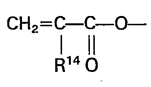
- ambifunctional silanes are materials (monomers and/or hydrolyzates and precondensates thereof) having a di- or trialkoxy silane on one end and a different polymerizable group, such as an epoxy, acryloyl (including methacryloyl), or vinyl group on the other end.
- a formula for these materials would be: wherein
- the more preferred compounds of this class are selected from those where m is 1 to 4 in formula 1) and in formulae 1) or 2) X' and X are selected from wherein
- t is 2 to 5
- R 9 is E is and R 13 is alkylene of 1 to 13 carbon atoms.
- These compounds may be pure monomers, or, particularly in the case of the epoxy-silanes, hydrolyzates or precondensates.
- copolymerizable materials may be combined therewith.
- copolymers are preferably combined with the compounds. Either aliphatic or cycloaliphatic epoxy comonomers are useful in the epoxy-terminated silanes, as are other copolymerizable silanes.
- Acrylates preferably diacryloyloxy and dimethacryloyloxy (as well as tri-, tetra-, and penta-functional acryloyloxy materials) are useful comonomers with both the acryloyloxy-terminated silanes and the polyfunctional acryloyloxy-substituted heterocyclics described above.
- the use of the copolymerizable materials in conjunction with the preferred compounds of the invention is well described in the prior art, as for examples U.S. Patent No. 4,049,861,4,101,513,4,084,021 and U.S. Patents 4 306 954,4 249 011 and 4 262 072.
- Preferred cationic photoinitiators are the SbF 6 -, PF 6 -, BF 4 - and AsF 6 - salts of polyaryl iodonium and sulfonium salts.
- Preferred free radical photoinitiators are polyaryl iodonium and sulfonium salts and the phenones.
- the compounds discussed above are generally preferred because they may be used without solvents. The absence of solvents prevents trapping of the solvents in the coating during cure.
- the preferred compounds as noted in the prior art described above, also produce highly abrasion resistant and solvent resistant articles which are particularly desirable.
- highly abrasion resistant materials are produced when the ambifunctional silanes comprise at least 30% by weight of the reactive ingredients.
- the heterocyclic acrylates at least 15% by weight and preferably 25% by weight of the composition should be the heterocyclic acryloyloxy materials for abrasion resistance and/or oxygen insensitivity.
- additives such as antioxidants, lubricants, surfactants, flow control factants, flow control aids, fillers, dyes, etc. may be present in the composition of the present invention.
- a highly hydrolyzed precondensate of y-glycidoxypropyl-trimethoxy silane (about 80-90% of methoxy groups removed) (70 gm) was mixed with 30 gm of 1,4-diglycidoxybutane and 2 gm of triarylsulfonium hexafluoroantimonate photocatalyst described in assignee's U.S. Patent No. 4,173,476 by shaking for 3 hours. Bubbles were then removed from the mixture by placing it in an evacuated chamber for 15 minutes. The resulting photopolymerizable material was used to make a video disc replica according to the following roll coating process.
- a nickel video disc stamper was utilized. Approximately 2.0 cm 3 of the material prepared as described above is spread by a cylindrical coating roller between a video disc stamper and a primed 0.18 mm polyester film. The sheet of 0.18 mm thick polyester film was positioned between the stamper and the roller to serve as a base element. This rolling process spread out a bubble free coating of resin composition over the surface of the stamper and simultaneously covered it with the polyester sheet. The stamper covered in this manner was then passed at 3 cm/sec under a 200 watt/2.54 cm high intensity medium pressure Hg vapor lamp. The UV exposure cured and hardened the resin composition. After this exposure, the laminated structure containing the replicated information was easily peeled from the nickel stamper. The sheet was then cut to produce a circular center hole and a circular outside edge, both concentric with the replicated information grooves.
- the resulting video disc replica had an information bearing layer which was approximately 10 ⁇ 5 Ilm thick which did not curl when laid on a flat surface. It retained this flatness after more than one year under ambient conditions and produced a good television picture when played on a commercial video disc player.
- a resin composition was prepared by mixing 60 gm of 1,3-bis 3-[2,2,2-(tri- acryloyloxymethyl)ethoxy]-2-hydroxypropyl-5,5-dimethyl-2,4-imidazolidinedione (containing approximately 25% pentaerythritol tetraacrylate), referred to as Compound A in the remaining examples, with 40 gm 1,6-hexanediol diacrylate and 2 gm 2,2-dimethoxy-2-phenyl-acetophenone. This composition was mixed by shaking and then filtered through a 5 pm filter. The resulting photopolymerizable material was used to make a video disc replica according to the roll coating process of Example 1 using polyvinylidenechloride primed polyester as the substrate.
- the resulting video disc replica had an information bearing layer 10 ⁇ 5 ⁇ m thick. This disc lay flat when placed on a level surface. It provided a good television picture when played on a video disc player.
- a resin composition was prepared by mixing 70 gm of Compound A with 30 gm of hexanediol diacrylate and 2 gm of the photoinitiator of Example 1. The resulting material was used to make a video disc according to the procedure of Example 1.
- the video disc replica made in this way had a cured information bearing layer 6 + 2 ⁇ m thick. This disc lay flat when placed on a level surface. It provided a good television picture when played on a video disc player.
- a resin composition was prepared by mixing 30 gm of Compound A with 70 gm of hexanediol diacrylate and 2 gm of the photoinitiator of Example 1. The resulting material was used to make a video disc according to the procedure of Example 1.
- the video disc replica made in this way had a cured information bearing layer 5 ⁇ 2.5 pm thick. This disc lay flat when placed on a level surface. It provided a good television picture when played on a video disc player.
- a sample of commercially available polyvinylchloride film 36 cm (14 inches) square was prepared for use as a video disc substrate in the following way.
- the sheet was placed between two flat, smooth, chrome-steel plates.
- the plates were in turn sandwiched between four layers of cardboard and the resulting stack pressed for ten minutes in a hydraulic press.
- the press was operated with a force of 11 metric tons, and the press platens were heated to 160°C. This pressing operation reduced the surface roughness of the manufactured film and provided a substrate of suitable flatness.
- the substrate thus prepared was used to make a video disc replica according to the procedure of Example 2, except that the surface of the polyvinylchloride opposite the information bearing layer was also coated with the resin composition.
- the cured polymer showed good adhesion to the otherwise untreated surface of the polyvinylchloride substrate.
- the disc lay flat when placed on a level surface and provided a good television picture when played on a video disc player. Information could be read from this disc with the laser beam incident from either side of the disc.
- a sheet of cast acrylic material (polymethylmethacrylate) 1000 pm thick was sputter etched according to the following procedure to promote adhesion of the polymer.
- the acrylic substrate was placed in a Vecco Model 776 radio frequency diode sputtering apparatus operating at a frequency of 13.56 MHz. The substrate was then subjected to a radio frequency sputter etch.
- Example 2 The resin composition of Example 2 and the roll coating technique of Example 2 was used to prepare a video disc replica with the above described substrate.
- the semiflexible substrate was allowed to bend slightly when it was lowered slowly onto the stamper as the roller moved along.
- the resin composition was cured with a blank of low intensity UV lamps, and the replica removed from the stamper.
- An aluminum coating 30 nm thick was vapor coated onto the surface of the information bearing layer.
- a circular hole was cut in the center of the disc, and a circular outer edge was cut.
- the resulting disc was then played on a video disc player; a good television picture was obtained.
- the laser beam of the player was incident through the uncoated acrylic surface and reflected by the aluminum coating on the information bearing surface.
- a resin composition was made by mixing 70 gm of a precondensate of y-methacryloxy- propyltrimethoxy silane with 30 gm of hexanedioldiacrylate and 2 gm of 2,2-dimethoxy-2-phenylacetophenone.
- the resulting material was used to make a video disc according to the procedure of Example 1 except that the resin was cured under a bank of low intensity "black lights" for 15 minutes.
- the video disc replica made in this way had a cured information bearing layer 6 ⁇ 3.5 pm thick. This disc lay flat when placed on a level surface. It provided a good television picture when played on a video disc player.
- a resin composition was made by mixing 90 gm y-glycidoxypropyltrimethoxy silane with 10 gm limonene oxide and 2 gm of the photocatalyst of Example 1.
- the resulting material was used to make a video disc according to the procedure of Example 1 except that the resin was cured under a bank of low intensity "black lights" for 30 minutes.
- the video disc replica made in this way had a cured information bearing layer 5 ⁇ 3 pm thick. This disc lay flat when placed on a level surface. It provided a television picture when played on a video disc player but gave a slightly low signal level.
- a video recording was made in a commercially available polymeric photoresist layer and the layer developed by standard wash-development techniques after exposure. The recording was then vapor coated with 10 pm of chrome. The resulting photoresist stamper was used in place of a nickel stamper to make a video disc replica according to the procedures of Example 1. This replica was playable. When vapor coated with 10 nm of chrome and used in place of a nickel stamper, repeated playable replications were made.
- a photoresist stamper was made according to the procedure of Example 9. This stamper was used in place of a nickel stamper to produce a video disc replica according to the procedure of Example 2. This replica provided a good television picture when played on a video disc player and again there was no significant wear on the stamper.
Abstract
Description
- The present invention relates to information carrying systems and more particularly to discs which carry light readable or stylus readable information. These discs may be useful in carrying information which is convertible to electronic signals for such varied uses as audio/visual recordings, or even computer type information retrieval.
- Information retrieval in the form of discs having information distributed in a circular, arc-like, or spiral pattern has been available in various forms for many years. Early forms of musical reproduction equipment, for example, used discs with either holes or protuberances to pluck an array of strings or vibrating posts to produce music. Early displays of moving pictures operated by rotation of a disc bearing consecutive images on the periphery. The most common form of storing reproductions of musical performances, which has been in use for about one hundred years, is the phonograph record which uses a spiral pattern of grooves having vertical and horizontal modulations to generate signals which can be converted to sound.
- With the introduction of the laser to industry, a new information storage system was developed which comprised a disc having a circular or spiral pattern of depressions or protuberances which would disturb, reflect, or refract incident light patterns. These information storing discs, often used for storage of audio/visual information and generally referred to as video discs, are well known in the art. Such U.S. Patents as 3,658,954; 3,795,534; 3,798,134; 3,855,426; 3,901,994; 4,124,672; 4,126,716; and 4,130,620 show various constructions, compositions, and processes for forming video discs.
- In addition to the laser readable video disc, another commercial construction is used which is more similar to the classic phonograph recording. This type of construction, as described in RCA Review, Vol. 39, No. 1 March, 1978, comprises a spiral array of grooves which is tracked by a stylus. The grooves are impressed with coded information in the form of vertical and/or radial modulations.
- In GB-A-1 037 835 in the technological field of the manufacture of printing plates a polymerizable material is deposited onto a matrix. Rollers assist in spreading the material out. Liquid is applied continually in advance of rollers and there is a danger that this will cause the entrapment of air. The entrapment of air which can be tolerated to a certain extent in the formation of relief printing plate would be intolerable for video discs where the dimensions of information units are much smaller.
- Techniques for the manufacture of video discs are described in US-A-4 272 574 (FR-A-2 423 322 and "Mastering and Replication of Reflective Videodiscs" IEEE, Transactions on Consumer Electronics, November 1976, pp 318-326. This latter article describes a known method of casting video discs wherein a thin film of liquid resin monomer is applied to a preformed substrate and then the liquid resin is pressed against an encoded mold surface at relatively low pressure. After contact the resin polymerizes (either spontaneously or with the help of heat or radiation and the disc may be separated from the mold.
- Even though the various prior art video disc systems are read by totally different techniques, they are affected by similar, if not identical, problems. Imperfections in the depressions, protuberances, or modulations cause undesirable or spurious signals to be generated. The imperfections can be produced during manufacture of the disc or can develop from wear during use or manipulation of the disc.
- The present invention relates to information storage discs for use with laser or stylus readout systems which have good fidelity and resistance to wear.
- More particularly, the present invention relates to a process for forming information storage discs or disc blanks for use with laser or stylus readout systems.
- It has been found that high density information storage discs or disc blanks comprising discs having a circular, arc-like, or spiral pattern of depressions, protuberances, and/or grooves with or without (in the case of blanks) modulations, can be made by photopolymerization of a liquid mass properly deposited between a stamper and a substrate to which the polymerized mass is to adhere.
- According to the present invention there is provided a method of making a video or similar high information density disc or disc blank which comprises depositing on a first surface a mass of photopolymerizable liquid composition, said mass containing sufficient material to form the entire disc; spreading said composition to form a layer on the first surface, by moving a flexible second surface from a non-parallel position to a parallel position with respect to said first surface, so as to advance a bead of said composition in front of the flexible surface, one of said surfaces being a patterned surface with a circular arcuate or spiral pattern of depressions, protuberances, grooves with or without modulations or combinations of such depressions, protuberances or grooves, photopolymerizing said layer of composition and bonding same to said flexible second surface, and removing the polymerized layer from said patterned surface.
- The use of liquid photopolymerizable materials to form replicated information carrying discs is known in the art, such as for example Belgian Patent 859,711. The process of the present invention provides a number of advantages over prior art methods, including those using photopolymerizable liquids.
- The prior art processes, involving the deposition of the liquid on the stamper or substrate (by knife coating or spin coating) and subsequent application of the substrate, are two step processes. The substrate is usually laid over the liquid coated master and the amounts of liquid material and its general displacement over the master is difficult to control. Excess liquid is usually applied to insure minimum thickness in the information carrying layer.
- The advancement of a bead of liquid according to the present invention as by the substrate being rolled out over the master has been found to remove substantially all of the air in the mold. The leading edge of the bead tends to pick up and carry the air without redepositing it in progressive features of the master because the air bubbles rupture, releasing the gas. This eliminates beading and wicking of the thin liquid film both of which creates voids. The need for levelling agents, which can deleteriously affect the physical properties of the coating or raise the cost of materials used is avoided.
- The process of the present invention also offers advantages over the thermal molding or embossing processes of the prior art. Photopolymerization can, with reasonable selection of photocatalysts or photoinitiators, be performed at faster rates and with simpler equipment with no loss of quality as compared to thermal molding and embossing processes. Little pressure is used and no heat curing is required, so little stress is applied to or built into the discs. Because little stress and softer materials are used, the life of the stamper is believed to also be extended. In fact, with the process of the present invention, a non-metallic master may be used to provide numerous replications. Such organic resin stampers (usually with a thin metal coating) are far less expensive than metal stampers used in conventional processes.
- As long as the substrate or master is able to bend sufficiently to enable the formation of a bead and propagation of that bead as the bend-point is moved forward, the substrate or master is sufficiently flexible. Materials that would otherwise be considered semi-flexible are therefore useful in the practice of the present invention.
- These and other features can be seen with a review of the drawings.
-
- Figure 1 shows a cross-section view of an information carrying disc.
- Figure 2 shows a view of apparatus which could typically be used to practice the present invention.
- Figure 3 shows a side view of apparatus which could typically be used to practice the present invention.
- Information carrying elements are made according to the process of the present invention. A cross-section of an information carrying disc 2 is shown in Figure 1. A
substrate 4 carries aninformation carrying layer 6 which has depressions or grooves 7 or protuberances 5 thereon. As hereinafter described,substrate 4 may be opaque or transparent. If the substrate is opaque to the radiation used for curing the photopolymerizable liquid, a stamper, e.g. of polymeric film, substantially transparent to this radiation must be used. A reflective layer or primer layer or both may be present between thesubstrate 4 and theinformation carrying layer 6. - The process itself can be more readily understood from Figure 2. The
substrate 4 is moved by anelement 12 over thestamper carrying surface 10. On this surface, facing upwards towards the advancingsubstrate 4 is anegative mold 8 of the information carrying disc or disc blank to be replicated. The pattern 9 on themold 8 is the specific pattern to be duplicated. Aselement 12advances substrate 4 so that it flattens out over thesurface 10, a mass ofphotopolymerizable liquid 14 is also advanced over thesurface 10 and the pattern 9 on themold 8. If the stamper is both transparent and flexible, the relative positions of the substrate and stamper may be reversed. - The dynamics of the process can be readily seen in Figure 3. As
element 12 advances thesubstrate 4 over thestamper 10, a bead of photopolymerizable liquid 14 is advanced in front of thesubstrate 4. The liquid 14 fills thedepressions 16 in themold 8. The photopolymerizable liquid 14, after it has been spread over themold 8 and when thesubstrate 4 is lying over it can be cured by irradiation transmitted through either themold 8 from thebackside 18 of thestamper 10 or through thesubstrate 4. After curing of the photopolymerizable liquid 14, thesubstrate 4 is lifted off of themold 8 carrying the polymerized resin with it. This produces the article of Figure 1. - Another manner of propagating the advancing bead of liquid within the practice of the present invention is with an essentially flat layer. By placing the mass of liquid on one side of an upright or angled rigid substrate or master, the rigid layer may be rotated about the lower edge so as to squeeze a bead of liquid forward until the rigid layer and the other substrate enclosing the liquid are essentially parallel. This operates substantially better than would simple hand spreading of a liquid and pressing with a stamper because of reduced air entrapment. This method can be described as 1) moving a first layer relative to a second layer from a non-parallel to a parallel position so as to spread in the form of a bead, a photopolymerizable liquid mass between the two layers, one of said layers having a patterned surface facing the other layer with a circular, arc-like, or spiral pattern of depressions, protuberances, grooves with or without modulations or combinations of depressions, protuberances and grooves with or without modulations, the other of said layers having a surface to which the photopolymerizable liquid will bond upon polymerizing, 2) then irradiating said photopolymerizable liquid to polymerize said liquid and bond the polymer formed to the other of said layers, and then 3) removing said polymeric resin and the layer to which it is bonded from said patterned surface.
- The composition of the photopolymerizable material may be any material which polymerizes into a polymeric resin which has satisfactory properties for use in an information carrying disc or disc blank. The polymeric resin usually is at least transparent for the radiation used to read information off the disc. Ordinarily a fairly narrow band of radiation is used for these purposes so that the photopolymerizable liquid and the polymeric resin only preferably should be transmissive of at least 50% of the radiation in a 100 nm, 50 nm, or 30 nm band. Preferably the layer is transmissive of at least 75 to 90% of the radiation within such a band.
- Many different types of photopolymerizable systems are useful. Acrylates (including methacrylates), epoxy resins, silanes, vinyl resins, and others are useful photopolymerizable systems. The preferred polymerizable systems of the present invention are ambifunctional silanes and polyacryloyl polymerizable systems. Ambifunctional silanes are materials (monomers and/or hydrolyzates and precondensates thereof) having a di- or trialkoxy silane on one end and a different polymerizable group, such as an epoxy, acryloyl (including methacryloyl), or vinyl group on the other end. A formula for these materials would be:

- A is an epoxy, acryloyloxy, or vinyl containing group,
- R is a divalent organic radial,
- R1 is a monovalent organic radical such that OR1 is hydrolyzable,
- R2 is a monovalent organic radical, and
- n is a 0 or 1, and most preferably 0.
- A is preferably selected from the groups

- a and b are selected from H, or, when fused together, represent the atoms necessary to form a 5- or 6-membered cycloaliphatic ring, and
- R3 is H or CH3-
- R is preferably an alkylene group which may be interrupted with an oxygen atom. Preferably the group has from 1 to 16 total carbon atoms and more preferably may be represented by the formula

- p is 1 to 6,
- m is 0 or 1, and
- q is 1 to 6.
- R' is preferably alkyl or acyl of 1 to 10 carbon atoms and most preferably alkyl of 1 to 3 carbon atoms.
- R2 may be H or alkyl of 1 to 10 carbon atoms.
- As noted above, these compounds are most preferably trialkoxy silanes.
- A preferred class of polyacryloyl compounds for use in the process of the present invention is described below. The class herein defined as "polyacryloyl heterocyclics" are represented by the formulae:

- A' and A2 independently are alkoxyalkyl groups having terminal ethylenic unsaturation and having the formula

- R9-0- is a monovalent residue of an aliphatic terminally unsaturated primary alcohol, R90H, formed by the removal of the active hydrogen from the primary -OH group, R9 having the formula:

- E is

- c is an integer of from 1 to 6,
- d is zero or an integer of from 1 to 6,
- R10 and R14 are independently selected from hydrogen and methyl,
- R13 is an aliphatic group having from 1 to 15 carbon atoms, and no more than two catenary oxygen or carboxy groups, a valence of t+1,
- t is an integer of from 1 to 5,
- R11 is selected from hydrogen and groups of the formula


- R15 is selected from alkyl and alkenyl groups
- R16 is an aliphatic or aromatic group of up to eight carbon atoms,
- R12 is an alkylene group of from 1 to 6 carbon atoms with up to one catenary oxygen atom, and
- Z is a heterocyclic group of the formula

- X is a divalent group which is required to complete a 5- or 6-membered heterocyclic ring, or

- R" and R18 independently represent hydrogen or methyl,
- R19 represents hydrogen, an alkyl group, or a phenyl group,
- R18 and R19 together may represent a trimethylene or tetramethylene group,
- r represents a number of from 1 to 30,
- s is 2 or 3, and
- A represents a group of the formula

- X1 represents the divalent radical necessary to complete a 5- or 6-membered heterocyclic ring group
- The more preferred compounds of this class are selected from those where m is 1 to 4 in formula 1) and in formulae 1) or 2) X' and X are selected from

- R4, R5, R6 and R7 independently represent hydrogen, and alkyl group, an alkylene group, a cycloalkyl group, or a phenyl group, and
- RB represents hydrogen, an aliphatic group, or an aromatic group.
except, that with regard to X, R8 is an alkyoxyalkyl group as defined for A1 and A2. Most preferably X and X1 are selected from
- R4 and R5 are hydrogen or alkyl of 1 to 4 carbon atoms.
- It is also preferred that t is 2 to 5, R9 is

- These compounds, as noted above, may be pure monomers, or, particularly in the case of the epoxy-silanes, hydrolyzates or precondensates. In addition, copolymerizable materials may be combined therewith. In fact, in some instances, copolymers are preferably combined with the compounds. Either aliphatic or cycloaliphatic epoxy comonomers are useful in the epoxy-terminated silanes, as are other copolymerizable silanes. Acrylates, preferably diacryloyloxy and dimethacryloyloxy (as well as tri-, tetra-, and penta-functional acryloyloxy materials) are useful comonomers with both the acryloyloxy-terminated silanes and the polyfunctional acryloyloxy-substituted heterocyclics described above. The use of the copolymerizable materials in conjunction with the preferred compounds of the invention is well described in the prior art, as for examples U.S. Patent No. 4,049,861,4,101,513,4,084,021 and
U.S. Patents 4 306 954,4 249 011 and 4 262 072. - In each of these systems, it is desirable to add materials that will render them sufficiently photosensitive, for the preferred compounds and compositions made therefrom are not inherently photosensitive to a useful degree. With the silane containing compounds, at least a cationic photoinitiator is desirable, and when using the acryloyloxy- terminated silane, or the polyaryloyloxy-containing heterocyclics a free radical photoinitiator should also be present. These materials are well known in the art and are thoroughly described in U.S. Patent Nos. 4,049,861, 4,101,513, 4,058,400, 4,058,401 and U.S. Patent Application Serial No. 51,876, 51,877 and 51,888, and the literature. Preferred cationic photoinitiators are the SbF6-, PF6-, BF4- and AsF6- salts of polyaryl iodonium and sulfonium salts. Preferred free radical photoinitiators are polyaryl iodonium and sulfonium salts and the phenones.
- The compounds discussed above are generally preferred because they may be used without solvents. The absence of solvents prevents trapping of the solvents in the coating during cure. The preferred compounds, as noted in the prior art described above, also produce highly abrasion resistant and solvent resistant articles which are particularly desirable. In the case of the ambifunctional silanes, and particularly the epoxy- and acryloyloxy-terminated silanes, highly abrasion resistant materials are produced when the ambifunctional silanes comprise at least 30% by weight of the reactive ingredients. With the described heterocyclic acrylates, at least 15% by weight and preferably 25% by weight of the composition should be the heterocyclic acryloyloxy materials for abrasion resistance and/or oxygen insensitivity.
- Other additives such as antioxidants, lubricants, surfactants, flow control factants, flow control aids, fillers, dyes, etc. may be present in the composition of the present invention. These and other aspects of the invention may be understood from the following examples.
- A highly hydrolyzed precondensate of y-glycidoxypropyl-trimethoxy silane (about 80-90% of methoxy groups removed) (70 gm) was mixed with 30 gm of 1,4-diglycidoxybutane and 2 gm of triarylsulfonium hexafluoroantimonate photocatalyst described in assignee's U.S. Patent No. 4,173,476 by shaking for 3 hours. Bubbles were then removed from the mixture by placing it in an evacuated chamber for 15 minutes. The resulting photopolymerizable material was used to make a video disc replica according to the following roll coating process.
- A nickel video disc stamper was utilized. Approximately 2.0 cm3 of the material prepared as described above is spread by a cylindrical coating roller between a video disc stamper and a primed 0.18 mm polyester film. The sheet of 0.18 mm thick polyester film was positioned between the stamper and the roller to serve as a base element. This rolling process spread out a bubble free coating of resin composition over the surface of the stamper and simultaneously covered it with the polyester sheet. The stamper covered in this manner was then passed at 3 cm/sec under a 200 watt/2.54 cm high intensity medium pressure Hg vapor lamp. The UV exposure cured and hardened the resin composition. After this exposure, the laminated structure containing the replicated information was easily peeled from the nickel stamper. The sheet was then cut to produce a circular center hole and a circular outside edge, both concentric with the replicated information grooves.
- The resulting video disc replica had an information bearing layer which was approximately 10±5 Ilm thick which did not curl when laid on a flat surface. It retained this flatness after more than one year under ambient conditions and produced a good television picture when played on a commercial video disc player.
- A resin composition was prepared by mixing 60 gm of 1,3-bis 3-[2,2,2-(tri- acryloyloxymethyl)ethoxy]-2-hydroxypropyl-5,5-dimethyl-2,4-imidazolidinedione (containing approximately 25% pentaerythritol tetraacrylate), referred to as Compound A in the remaining examples, with 40 gm 1,6-hexanediol diacrylate and 2 gm 2,2-dimethoxy-2-phenyl-acetophenone. This composition was mixed by shaking and then filtered through a 5 pm filter. The resulting photopolymerizable material was used to make a video disc replica according to the roll coating process of Example 1 using polyvinylidenechloride primed polyester as the substrate.
- The resulting video disc replica had an
information bearing layer 10±5 µm thick. This disc lay flat when placed on a level surface. It provided a good television picture when played on a video disc player. - A resin composition was prepared by mixing 70 gm of Compound A with 30 gm of hexanediol diacrylate and 2 gm of the photoinitiator of Example 1. The resulting material was used to make a video disc according to the procedure of Example 1. The video disc replica made in this way had a cured
information bearing layer 6+ 2 µm thick. This disc lay flat when placed on a level surface. It provided a good television picture when played on a video disc player. - A resin composition was prepared by mixing 30 gm of Compound A with 70 gm of hexanediol diacrylate and 2 gm of the photoinitiator of Example 1. The resulting material was used to make a video disc according to the procedure of Example 1. The video disc replica made in this way had a cured information bearing layer 5±2.5 pm thick. This disc lay flat when placed on a level surface. It provided a good television picture when played on a video disc player.
- A sample of commercially available polyvinylchloride film 36 cm (14 inches) square was prepared for use as a video disc substrate in the following way. The sheet was placed between two flat, smooth, chrome-steel plates. The plates were in turn sandwiched between four layers of cardboard and the resulting stack pressed for ten minutes in a hydraulic press. The press was operated with a force of 11 metric tons, and the press platens were heated to 160°C. This pressing operation reduced the surface roughness of the manufactured film and provided a substrate of suitable flatness.
- The substrate thus prepared was used to make a video disc replica according to the procedure of Example 2, except that the surface of the polyvinylchloride opposite the information bearing layer was also coated with the resin composition. The cured polymer showed good adhesion to the otherwise untreated surface of the polyvinylchloride substrate. The disc lay flat when placed on a level surface and provided a good television picture when played on a video disc player. Information could be read from this disc with the laser beam incident from either side of the disc.
- A sheet of cast acrylic material (polymethylmethacrylate) 1000 pm thick was sputter etched according to the following procedure to promote adhesion of the polymer. The acrylic substrate was placed in a Vecco Model 776 radio frequency diode sputtering apparatus operating at a frequency of 13.56 MHz. The substrate was then subjected to a radio frequency sputter etch.
- The resin composition of Example 2 and the roll coating technique of Example 2 was used to prepare a video disc replica with the above described substrate. The semiflexible substrate was allowed to bend slightly when it was lowered slowly onto the stamper as the roller moved along. The resin composition was cured with a blank of low intensity UV lamps, and the replica removed from the stamper. An aluminum coating 30 nm thick was vapor coated onto the surface of the information bearing layer. A circular hole was cut in the center of the disc, and a circular outer edge was cut. The resulting disc was then played on a video disc player; a good television picture was obtained. The laser beam of the player was incident through the uncoated acrylic surface and reflected by the aluminum coating on the information bearing surface.
- A resin composition was made by mixing 70 gm of a precondensate of y-methacryloxy- propyltrimethoxy silane with 30 gm of hexanedioldiacrylate and 2 gm of 2,2-dimethoxy-2-phenylacetophenone. The resulting material was used to make a video disc according to the procedure of Example 1 except that the resin was cured under a bank of low intensity "black lights" for 15 minutes. The video disc replica made in this way had a cured
information bearing layer 6±3.5 pm thick. This disc lay flat when placed on a level surface. It provided a good television picture when played on a video disc player. - A resin composition was made by mixing 90 gm y-glycidoxypropyltrimethoxy silane with 10 gm limonene oxide and 2 gm of the photocatalyst of Example 1. The resulting material was used to make a video disc according to the procedure of Example 1 except that the resin was cured under a bank of low intensity "black lights" for 30 minutes. The video disc replica made in this way had a cured information bearing layer 5±3 pm thick. This disc lay flat when placed on a level surface. It provided a television picture when played on a video disc player but gave a slightly low signal level.
- A video recording was made in a commercially available polymeric photoresist layer and the layer developed by standard wash-development techniques after exposure. The recording was then vapor coated with 10 pm of chrome. The resulting photoresist stamper was used in place of a nickel stamper to make a video disc replica according to the procedures of Example 1. This replica was playable. When vapor coated with 10 nm of chrome and used in place of a nickel stamper, repeated playable replications were made.
- A photoresist stamper was made according to the procedure of Example 9. This stamper was used in place of a nickel stamper to produce a video disc replica according to the procedure of Example 2. This replica provided a good television picture when played on a video disc player and again there was no significant wear on the stamper.
Claims (6)


Applications Claiming Priority (2)
| Application Number | Priority Date | Filing Date | Title |
|---|---|---|---|
| US117467 | 1980-02-01 | ||
| US06/117,467 US4374077A (en) | 1980-02-01 | 1980-02-01 | Process for making information carrying discs |
Publications (3)
| Publication Number | Publication Date |
|---|---|
| EP0044345A4 EP0044345A4 (en) | 1982-01-08 |
| EP0044345A1 EP0044345A1 (en) | 1982-01-27 |
| EP0044345B1 true EP0044345B1 (en) | 1985-12-04 |
Family
ID=22373102
Family Applications (1)
| Application Number | Title | Priority Date | Filing Date |
|---|---|---|---|
| EP81900699A Expired EP0044345B1 (en) | 1980-02-01 | 1980-12-23 | Process for making video and similar discs |
Country Status (6)
| Country | Link |
|---|---|
| US (1) | US4374077A (en) |
| EP (1) | EP0044345B1 (en) |
| JP (1) | JPS57500017A (en) |
| CA (1) | CA1152941A (en) |
| DE (1) | DE3071280D1 (en) |
| WO (1) | WO1981002236A1 (en) |
Families Citing this family (90)
| Publication number | Priority date | Publication date | Assignee | Title |
|---|---|---|---|---|
| NL8300417A (en) * | 1983-02-04 | 1984-09-03 | Philips Nv | METHOD AND APPARATUS FOR MANUFACTURING A PLASTIC INFORMATION CARRIER WITH A LAYERED STRUCTURE |
| US4906315A (en) * | 1983-06-20 | 1990-03-06 | Mcgrew Stephen P | Surface relief holograms and holographic hot-stamping foils, and method of fabricating same |
| FR2553531B1 (en) * | 1983-10-14 | 1995-12-29 | Canon Kk | PHOTOPOLYMERIZABLE MONOMER FOR OPTICAL RECORDING MEDIUM AND MEDIUM CONTAINING SAME |
| JPS6116815A (en) * | 1984-07-04 | 1986-01-24 | Sumitomo Bakelite Co Ltd | Manufacture of optical disk substrate |
| JPS60121442A (en) * | 1983-12-06 | 1985-06-28 | Canon Inc | Photosensitive record memory medium and recording/ reproducing method |
| US4614705A (en) * | 1984-02-17 | 1986-09-30 | Ricoh Co., Ltd. | Optical information recording medium |
| US4968370A (en) * | 1984-07-19 | 1990-11-06 | Hallmark Cards, Incorporated | Replication of information carriers |
| US4790893A (en) * | 1984-07-19 | 1988-12-13 | Hallmark Cards, Inc. | Replication of information carriers |
| US5174943A (en) * | 1984-08-08 | 1992-12-29 | 3D Systems, Inc. | Method for production of three-dimensional objects by stereolithography |
| US5344298A (en) * | 1984-08-08 | 1994-09-06 | 3D Systems, Inc. | Apparatus for making three-dimensional objects by stereolithography |
| US4929402A (en) * | 1984-08-08 | 1990-05-29 | 3D Systems, Inc. | Method for production of three-dimensional objects by stereolithography |
| US5236637A (en) * | 1984-08-08 | 1993-08-17 | 3D Systems, Inc. | Method of and apparatus for production of three dimensional objects by stereolithography |
| US4575330A (en) * | 1984-08-08 | 1986-03-11 | Uvp, Inc. | Apparatus for production of three-dimensional objects by stereolithography |
| US5554336A (en) * | 1984-08-08 | 1996-09-10 | 3D Systems, Inc. | Method and apparatus for production of three-dimensional objects by stereolithography |
| JPH0610886B2 (en) * | 1984-11-01 | 1994-02-09 | 株式会社リコー | Optical information recording medium |
| US4756856A (en) * | 1984-12-20 | 1988-07-12 | Polaroid Corporation | Method of and apparatus for forming surface of magnetic media |
| US4619804A (en) * | 1985-04-15 | 1986-10-28 | Eastman Kodak Company | Fabricating optical record media |
| US4632898A (en) * | 1985-04-15 | 1986-12-30 | Eastman Kodak Company | Process for fabricating glass tooling |
| US4652498A (en) * | 1985-10-22 | 1987-03-24 | Minnesota Mining And Manufacturing Company | Environmentally protected optical recording media |
| NL8503234A (en) * | 1985-11-25 | 1987-06-16 | Philips Nv | DIE. |
| US4665006A (en) * | 1985-12-09 | 1987-05-12 | International Business Machines Corporation | Positive resist system having high resistance to oxygen reactive ion etching |
| JPS62141661A (en) * | 1985-12-16 | 1987-06-25 | Ricoh Co Ltd | Optical information recording medium |
| DE3701801A1 (en) * | 1986-01-22 | 1987-07-23 | Ricoh Kk | OPTICAL INFORMATION RECORDING MATERIAL |
| US4877666A (en) * | 1987-08-11 | 1989-10-31 | Kerdix, Inc. | Magneto-optic substrates |
| US4963300A (en) * | 1987-12-15 | 1990-10-16 | Ciba-Geigy Corporation | Process for the preparation of laminates |
| US5175030A (en) * | 1989-02-10 | 1992-12-29 | Minnesota Mining And Manufacturing Company | Microstructure-bearing composite plastic articles and method of making |
| EP0405582A3 (en) * | 1989-06-30 | 1992-07-08 | E.I. Du Pont De Nemours And Company | Method for making optically readable media containing embossed information |
| JPH0354742A (en) * | 1989-07-21 | 1991-03-08 | Japan Synthetic Rubber Co Ltd | Optical disk, production thereof and reading method thereof |
| US5316849A (en) * | 1989-10-26 | 1994-05-31 | Minnesota Mining And Manufacturing Company | Reclosable mechanical fastener based on a composite article |
| US5888335A (en) * | 1989-10-26 | 1999-03-30 | Minnesota Mining And Manufacturing Company | Multiple releasable contact responsive fasteners |
| US5196266A (en) * | 1989-10-26 | 1993-03-23 | Minnesota Mining And Manufacturing Company | Reclosable mechanical fastener based on a composite article |
| US6004670A (en) * | 1989-10-26 | 1999-12-21 | Minnesota Mining And Manufacturing Company | Multiple releasable contact responsive fasteners |
| US5254390B1 (en) * | 1990-11-15 | 1999-05-18 | Minnesota Mining & Mfg | Plano-convex base sheet for retroreflective articles |
| US5406544A (en) * | 1991-07-25 | 1995-04-11 | Clark; Bryan K. | Low cost substrate for bump-forming recording media |
| US5360270A (en) * | 1992-04-28 | 1994-11-01 | Minnesota Mining And Manufacturing Company | Reusable security enclosure |
| US5201101A (en) * | 1992-04-28 | 1993-04-13 | Minnesota Mining And Manufacturing Company | Method of attaching articles and a pair of articles fastened by the method |
| DE69310212T2 (en) * | 1992-12-23 | 1997-09-25 | Honeywell Inc | REPRODUCTION OF OPTICALLY FLAT SURFACES |
| JP3428171B2 (en) * | 1994-09-09 | 2003-07-22 | 旭硝子株式会社 | Coated paper and method for producing the same |
| US5634245A (en) * | 1995-07-14 | 1997-06-03 | Minnesota Mining And Manufacturing Company | Structured surface fastener |
| US5804017A (en) * | 1995-07-27 | 1998-09-08 | Imation Corp. | Method and apparatus for making an optical information record |
| US20040137734A1 (en) * | 1995-11-15 | 2004-07-15 | Princeton University | Compositions and processes for nanoimprinting |
| US5912059A (en) * | 1996-08-16 | 1999-06-15 | Minnesota Mining And Manufacturing Company | Ostomy pouch having non-tacky fastener system |
| US6190838B1 (en) * | 1998-04-06 | 2001-02-20 | Imation Corp. | Process for making multiple data storage disk stampers from one master |
| CN1161769C (en) | 1998-04-06 | 2004-08-11 | 伊美申公司 | Reverse optical mastering for data storage disks |
| US6354827B1 (en) | 1998-11-12 | 2002-03-12 | Imation Corp. | Stamper assembly for manufacturing optical data storage disks |
| US6939474B2 (en) * | 1999-07-30 | 2005-09-06 | Formfactor, Inc. | Method for forming microelectronic spring structures on a substrate |
| US6517995B1 (en) * | 1999-09-14 | 2003-02-11 | Massachusetts Institute Of Technology | Fabrication of finely featured devices by liquid embossing |
| US20040190102A1 (en) * | 2000-08-18 | 2004-09-30 | Mullen Patrick W. | Differentially-cured materials and process for forming same |
| AU2001284844A1 (en) | 2000-08-18 | 2002-03-04 | Reflexite Corporation | Differentially cured materials and process for forming same |
| US7230764B2 (en) * | 2000-08-18 | 2007-06-12 | Reflexite Corporation | Differentially-cured materials and process for forming same |
| US6628598B2 (en) | 2000-12-05 | 2003-09-30 | Imation Corp. | Patterned media system |
| US7368222B2 (en) * | 2001-01-16 | 2008-05-06 | Dphi Acquisitions, Inc. | Optical data storage media with enhanced contrast |
| US6612917B2 (en) | 2001-02-07 | 2003-09-02 | 3M Innovative Properties Company | Abrasive article suitable for modifying a semiconductor wafer |
| US6616867B2 (en) | 2001-02-07 | 2003-09-09 | Imation Corp. | Multi-generation stampers |
| US6632129B2 (en) * | 2001-02-15 | 2003-10-14 | 3M Innovative Properties Company | Fixed abrasive article for use in modifying a semiconductor wafer |
| US6858253B2 (en) * | 2001-05-31 | 2005-02-22 | 3M Innovative Properties Company | Method of making dimensionally stable composite article |
| US6821460B2 (en) | 2001-07-16 | 2004-11-23 | Imation Corp. | Two-sided replication of data storage media |
| US6638692B1 (en) | 2001-07-16 | 2003-10-28 | Imation Corp. | Replicated regions on optical disks |
| US6936181B2 (en) * | 2001-10-11 | 2005-08-30 | Kovio, Inc. | Methods for patterning using liquid embossing |
| TW531742B (en) * | 2001-10-30 | 2003-05-11 | Ritek Corp | Manufacturing method for disk cover layer |
| US7008208B1 (en) | 2002-01-17 | 2006-03-07 | Imation Corp. | Grounded molding tool for manufacture of optical components |
| US6977052B1 (en) | 2002-01-18 | 2005-12-20 | Imation Corp | Check disk for optical data storage disk manufacturing |
| US6957608B1 (en) | 2002-08-02 | 2005-10-25 | Kovio, Inc. | Contact print methods |
| US7329537B2 (en) * | 2003-04-17 | 2008-02-12 | Nexcelom Bioscience, Llc | Micro-pattern embedded plastic optical film device for cell-based assays |
| WO2004099823A2 (en) * | 2003-05-02 | 2004-11-18 | Reflexite Corporation | Light-redirecting optical structures |
| US20050213482A1 (en) * | 2004-03-24 | 2005-09-29 | Imation Corp. | Multi-track mastering techniques |
| JP4393244B2 (en) * | 2004-03-29 | 2010-01-06 | キヤノン株式会社 | Imprint device |
| US20060073422A1 (en) * | 2004-09-28 | 2006-04-06 | Imation Corp. | Portable conformable deep ultraviolet master mask |
| US20060110568A1 (en) * | 2004-11-23 | 2006-05-25 | Imation Corp. | Multi-layers optical data storage disk masters |
| US7427466B2 (en) * | 2004-11-29 | 2008-09-23 | Imation Corp. | Anti-reflection optical data storage disk master |
| US20060263530A1 (en) * | 2005-05-19 | 2006-11-23 | General Electric Company | Process for making non-continuous articles with microstructures |
| US8179034B2 (en) * | 2007-07-13 | 2012-05-15 | 3M Innovative Properties Company | Light extraction film for organic light emitting diode display and lighting devices |
| US20090015142A1 (en) * | 2007-07-13 | 2009-01-15 | 3M Innovative Properties Company | Light extraction film for organic light emitting diode display devices |
| US20090147361A1 (en) * | 2007-12-07 | 2009-06-11 | 3M Innovative Properties Company | Microreplicated films having diffractive features on macro-scale features |
| US8068187B2 (en) * | 2008-06-18 | 2011-11-29 | 3M Innovative Properties Company | Stereoscopic 3D liquid crystal display apparatus having a double sided prism film comprising cylindrical lenses and non-contiguous prisms |
| US20100110551A1 (en) * | 2008-10-31 | 2010-05-06 | 3M Innovative Properties Company | Light extraction film with high index backfill layer and passivation layer |
| US7957621B2 (en) * | 2008-12-17 | 2011-06-07 | 3M Innovative Properties Company | Light extraction film with nanoparticle coatings |
| US8659830B2 (en) | 2009-12-21 | 2014-02-25 | 3M Innovative Properties Company | Optical films enabling autostereoscopy |
| US9117149B2 (en) | 2011-10-07 | 2015-08-25 | Industrial Technology Research Institute | Optical registration carrier |
| JP6949489B2 (en) | 2014-06-13 | 2021-10-13 | スリーエム イノベイティブ プロパティズ カンパニー | Optical stack for sparkle reduction |
| KR102387234B1 (en) | 2014-06-13 | 2022-04-18 | 쓰리엠 이노베이티브 프로퍼티즈 컴파니 | Optical stacks for sparkle reduction |
| US9862124B2 (en) | 2014-07-18 | 2018-01-09 | 3M Innovative Properties Company | Multilayer optical adhesives and methods of making same |
| US10761320B2 (en) | 2015-12-09 | 2020-09-01 | 3M Innovative Properties Company | Optical stack including a grating |
| US11708510B2 (en) | 2016-01-15 | 2023-07-25 | 3M Innovative Properties Company | Optical adhesive |
| DK3217401T1 (en) * | 2016-03-10 | 2017-12-11 | Joanneum Res Forschungsgmbh | Process for producing a high resolution analog audio storage medium |
| KR102330028B1 (en) | 2016-05-27 | 2021-11-24 | 쓰리엠 이노베이티브 프로퍼티즈 컴파니 | OLED display with improved color uniformity |
| KR102402862B1 (en) | 2016-10-28 | 2022-05-27 | 쓰리엠 이노베이티브 프로퍼티즈 컴파니 | Nanostructured Articles |
| KR20200011436A (en) | 2017-06-02 | 2020-02-03 | 쓰리엠 이노베이티브 프로퍼티즈 컴파니 | Optical film and optical system |
| JP7312765B2 (en) | 2018-04-20 | 2023-07-21 | スリーエム イノベイティブ プロパティズ カンパニー | Headsets and head-mounted displays |
| JP7369717B2 (en) | 2018-05-03 | 2023-10-26 | スリーエム イノベイティブ プロパティズ カンパニー | Light redirecting films, backlights, and display systems |
Family Cites Families (25)
| Publication number | Priority date | Publication date | Assignee | Title |
|---|---|---|---|---|
| DE1107958B (en) * | 1958-11-18 | 1961-05-31 | Richard Nicolaus Jun | Device for the continuous lamination of foils provided with clay grooves |
| BE639166A (en) * | 1962-11-01 | |||
| US3658954A (en) * | 1968-07-24 | 1972-04-25 | Mca Technology Inc | Duplicating process for video disc records |
| US3855426A (en) * | 1971-03-11 | 1974-12-17 | Philips Corp | Video disc recording and optical playback system therefor |
| US3945788A (en) * | 1971-06-29 | 1976-03-23 | Kabushiki Kaisha Asahi Shimbunsha | Apparatus of making reproduction printing plates |
| US3798134A (en) * | 1971-11-15 | 1974-03-19 | Printing Plate Supply Co | Method of making an electrotype shell |
| US3795534A (en) * | 1972-04-19 | 1974-03-05 | Rca Corp | Manufacture of video discs |
| NL164688C (en) * | 1973-10-15 | 1981-01-15 | Mca Disco Vision | METHOD FOR MANUFACTURING A VIDEO DISC IN WHICH A FORM IS FIRST MANUFACTURED |
| US3901994A (en) * | 1974-02-04 | 1975-08-26 | Rca Corp | Metallized video disc having a dielectric coating thereon |
| US4054635A (en) * | 1974-09-26 | 1977-10-18 | American Can Company | Copolymer of glycidyl methacrylate and allyl glycidyl ether |
| US4049861A (en) * | 1975-03-07 | 1977-09-20 | Minnesota Mining And Manufacturing Company | Abrasion resistant coatings |
| US4017581A (en) * | 1975-03-25 | 1977-04-12 | Xerox Corporation | Process for preparing relief printing masters and molds |
| US4112030A (en) * | 1975-05-02 | 1978-09-05 | Siemens Aktiengesellschaft | Method and system for the production of sheet or platter shaped information carriers |
| US4006271A (en) * | 1976-01-28 | 1977-02-01 | Itek Corporation | Abrasion resistant coating for polycarbonate substrates |
| DE2615605C2 (en) * | 1976-04-09 | 1978-06-01 | Polygram Gmbh, 2000 Hamburg | Disc-shaped information carrier and method for its manufacture |
| NL7611395A (en) * | 1976-10-15 | 1978-04-18 | Philips Nv | METHOD FOR MULTIPLICATING PLASTIC INFORMATION CARRIERS AND A CASTING RESIN, SUBSTRATE AND DIE USED IN THIS PROCESS. |
| US4225379A (en) * | 1976-12-13 | 1980-09-30 | Asahi Glass Company, Limited | Method of laminating plastic film and shaped metal substrates |
| US4101513A (en) * | 1977-02-02 | 1978-07-18 | Minnesota Mining And Manufacturing Company | Catalyst for condensation of hydrolyzable silanes and storage stable compositions thereof |
| JPS6052183B2 (en) * | 1977-02-23 | 1985-11-18 | 三菱レイヨン株式会社 | paint composition |
| US4175177A (en) * | 1978-02-24 | 1979-11-20 | Union Carbide Corporation | Crosslinkable copolymer of a lactone and a polyfunctional acrylate |
| NL7804036A (en) * | 1978-04-17 | 1979-10-19 | Philips Nv | OPTICALLY READABLE INFORMATION DISC. |
| FR2450683A1 (en) * | 1979-03-06 | 1980-10-03 | Thomson Brandt | METHOD AND APPARATUS FOR MAKING VIDEO DISC |
| US4294782A (en) * | 1979-04-10 | 1981-10-13 | Jerome Bauer | Method for substantially instantaneous liquid molding of an article |
| US4304806A (en) * | 1980-02-01 | 1981-12-08 | Minnesota Mining And Manufacturing Company | Information carrying discs |
| US4296158A (en) * | 1980-02-01 | 1981-10-20 | Minnesota Mining And Manufacturing Company | Information carrying discs |
-
1980
- 1980-02-01 US US06/117,467 patent/US4374077A/en not_active Expired - Lifetime
- 1980-12-23 DE DE8181900699T patent/DE3071280D1/en not_active Expired
- 1980-12-23 WO PCT/US1980/001728 patent/WO1981002236A1/en not_active Application Discontinuation
- 1980-12-23 JP JP56500932A patent/JPS57500017A/ja active Pending
- 1980-12-23 EP EP81900699A patent/EP0044345B1/en not_active Expired
- 1980-12-30 CA CA000367679A patent/CA1152941A/en not_active Expired
Non-Patent Citations (1)
| Title |
|---|
| IEEE TRANSACTIONS ON CONSUMER ELECTRONICS, vol. 22, no. 4, November 1976, New York, US WINSLOW et al. "Mastering and replication of reflective videodiscs", pages 318-326. * |
Also Published As
| Publication number | Publication date |
|---|---|
| EP0044345A4 (en) | 1982-01-08 |
| DE3071280D1 (en) | 1986-01-16 |
| JPS57500017A (en) | 1982-01-07 |
| CA1152941A (en) | 1983-08-30 |
| EP0044345A1 (en) | 1982-01-27 |
| US4374077A (en) | 1983-02-15 |
| WO1981002236A1 (en) | 1981-08-06 |
Similar Documents
| Publication | Publication Date | Title |
|---|---|---|
| EP0044345B1 (en) | Process for making video and similar discs | |
| US5281373A (en) | Process for producing substrate sheet for optical recording media | |
| US4482511A (en) | Method of manufacturing a stamper for information storage discs | |
| US4619804A (en) | Fabricating optical record media | |
| JP2578459B2 (en) | Information recording medium, method for manufacturing substrate for information recording medium, and mold for molding substrate for information recording medium | |
| JPH0354742A (en) | Optical disk, production thereof and reading method thereof | |
| KR100284728B1 (en) | Optical disk manufacturing method and optical disk by this manufacturing method | |
| CA1140261A (en) | Information carrying discs | |
| US5234633A (en) | Cast molding die and process for producing information recording medium using the same | |
| US4296158A (en) | Information carrying discs | |
| JP4078678B2 (en) | Manufacturing method of optical disk | |
| US4430363A (en) | Process of making information carrying systems | |
| US4948703A (en) | Ultraviolet light curable composition and use thereof | |
| JP2760381B2 (en) | Stamper | |
| AU536709B2 (en) | Process for making discs | |
| EP0306316B1 (en) | Methods of forming protective films on optical recording media | |
| AU544137B2 (en) | Information carrying discs | |
| USRE31533E (en) | Information carrying discs | |
| JPH024042B2 (en) | ||
| EP0323225A2 (en) | Cast molding die and process for producing information recording medium using the same | |
| JPH0326375A (en) | Continuous production of substrate for optical information recording medium | |
| JPS6334521B2 (en) | ||
| JPH02312024A (en) | Method for reinforcing back side of stamper for optical disk substrate, and production of optical disk substrate | |
| JPH0489277A (en) | Manufacture of molded roller | |
| JPS6074137A (en) | Recording disc |
Legal Events
| Date | Code | Title | Description |
|---|---|---|---|
| PUAI | Public reference made under article 153(3) epc to a published international application that has entered the european phase |
Free format text: ORIGINAL CODE: 0009012 |
|
| AK | Designated contracting states |
Designated state(s): DE FR GB NL |
|
| 17P | Request for examination filed |
Effective date: 19820201 |
|
| GRAA | (expected) grant |
Free format text: ORIGINAL CODE: 0009210 |
|
| AK | Designated contracting states |
Designated state(s): DE FR GB NL |
|
| REF | Corresponds to: |
Ref document number: 3071280 Country of ref document: DE Date of ref document: 19860116 |
|
| ET | Fr: translation filed | ||
| PLBI | Opposition filed |
Free format text: ORIGINAL CODE: 0009260 |
|
| 26 | Opposition filed |
Opponent name: N.V. PHILIPS' GLOEILAMPENFABRIEKEN Effective date: 19860903 |
|
| NLR1 | Nl: opposition has been filed with the epo |
Opponent name: N.V. PHILIPS' GLOEILAMPENFABRIEKEN |
|
| PGFP | Annual fee paid to national office [announced via postgrant information from national office to epo] |
Ref country code: NL Payment date: 19861231 Year of fee payment: 7 |
|
| RDAG | Patent revoked |
Free format text: ORIGINAL CODE: 0009271 |
|
| STAA | Information on the status of an ep patent application or granted ep patent |
Free format text: STATUS: PATENT REVOKED |
|
| 27W | Patent revoked |
Effective date: 19871213 |
|
| NLR2 | Nl: decision of opposition | ||
| GBPR | Gb: patent revoked under art. 102 of the ep convention designating the uk as contracting state |