EP0044461A2 - Lock-up control system for lock-up type automatic transmission - Google Patents
Lock-up control system for lock-up type automatic transmission Download PDFInfo
- Publication number
- EP0044461A2 EP0044461A2 EP81105264A EP81105264A EP0044461A2 EP 0044461 A2 EP0044461 A2 EP 0044461A2 EP 81105264 A EP81105264 A EP 81105264A EP 81105264 A EP81105264 A EP 81105264A EP 0044461 A2 EP0044461 A2 EP 0044461A2
- Authority
- EP
- European Patent Office
- Prior art keywords
- lock
- gear
- circuit
- valve
- signal
- Prior art date
- Legal status (The legal status is an assumption and is not a legal conclusion. Google has not performed a legal analysis and makes no representation as to the accuracy of the status listed.)
- Granted
Links
Images

Classifications
-
- F—MECHANICAL ENGINEERING; LIGHTING; HEATING; WEAPONS; BLASTING
- F16—ENGINEERING ELEMENTS AND UNITS; GENERAL MEASURES FOR PRODUCING AND MAINTAINING EFFECTIVE FUNCTIONING OF MACHINES OR INSTALLATIONS; THERMAL INSULATION IN GENERAL
- F16H—GEARING
- F16H61/00—Control functions within control units of change-speed- or reversing-gearings for conveying rotary motion ; Control of exclusively fluid gearing, friction gearing, gearings with endless flexible members or other particular types of gearing
- F16H61/14—Control of torque converter lock-up clutches
- F16H61/143—Control of torque converter lock-up clutches using electric control means
Abstract
Description
- The present invention relates to a lock-up control system for a lock-up type automatic transmission.
- Automatic transmissions are provided with a torque converter in a power transmission system thereof so as to increase a torque from an engine. The torque converter has a pump impeller driven by an engine to rotate an operating oil within the torque converter wherein the rotation of the operating oil causes a turbine runner to rotate under the reaction of a stator thereby multiplying the torque (torque converter state). Therefore, the torque converter, while in use, cannot help avoiding a slip between its pump impeller and its turbine runner, and therefore the automatic transmission provided with such torque converter in its power transmission system has an advantage of easy operation, but has a drawback of poor power transmission effeciency that leads to a poor fuel economy. To alleviate this drawback, there has been proposed a so-called a torque converter with a direct clutch (often referred also to as a lock-up torque converter) wherein during a relatively high vehicle speed operation range when a torque variation of an engine does not create a problem a turbine runner is directly connected to a pump impeller (lock-up state) thereby eliminating a slip therebetween, and a lock-up type automatic transmission provided with a torque converter of this kind in a power transmission system thereof is already employed in some vehicles.
- In the case of an automatic transmission having a torque converter which locks up whenever the vehicle operates in any one of the forward gear ratios and at a vehicle speed exceeding a predetermined vehicle speed which is set for operation in such any one gear ratio, since the lock-up ranges are adjoin one after another or overlap one after another with respect to the vehicle speed when the vehicle operates with an accelerator pedal depressed deeply, a gear shifting takes place with the torque converter left in the lock-up state when the automotive vehicle operates within any one of the lock-up ranges and with the accelerator pedal depressed deeply. If the gear shifting takes place with the torque converter left in the lock-up state, a torque variation owing to the gear shifting is not absorbed by the torque converter, thus allowing a great shock to take place upon gear shifting.
- Accordingly, it has been proposed to temporally release the lock-up state during gear shifting operation even when the vehicle is operating within any one of the lock-up ranges so as to allow the torque converter to operate in the torque converter state. For this purpose, a gear shifting detector is provided that generates a gear shift signal having a predetermined duration in response to and after the occurrence of a command for gear shifting between adjacent two gear ratios, thereby temporarlly releasing the lock-up state while the shift signal is present.
- In the proposed system, however, the duration of generation of a gear shift signal from each gear shifting detector circuit is constant, so that the suspention of the lock-up state which is caused by the gear shift signal continues during a constant duration irrespective of kinds of gear shifting commands. The duration for the automatic transmission to carry out the acutal gear shifting operation differs, owing to the construction of a hydraulic circuiit, depending upon kinds of gear shifting commands, viz., which friction unit or units are involved in the particular shifting in the automatic transmission, or depending upon an upshift or downshift even with the same adjacent two gear ratios, so that, in the event that the lock-up suspending duration is constant, although it might conform to the duration for a certain gear shifting operation, it does not conform to a duration for every other gear shifting operation, and is longer than the actual gear shifting duration or shorter than the actual gear shifting duration, thus causing the occurrence of a gear shift shock or impairing a driving feel.
- In this respect the present invention provides a lock-up type automatic transmission wherein a gear shifting detector circuit is so designed that the duration of generation of a gear shift signal is variable so as to conform a duration of suspension of a lock-up state to a various kinds of gear shifting operations, thus solving the above-mentioned problem.
- The duration for actual gear shifting varies with varying engine load. That is because the magnitude of line pressure which is used for actuating friction elements involved in gear shifting varies with the magnitude of the engine load, and the line pressure increases with increasing engine load under which condition the actual gear shifting takes place during a relatively short duration.
- Therefore, the present invention also proposes a lock-up type automatic transmission wherein a gear shifting detector circuit is so designed that the duration of generation of a gear shift signal is variable also with varying engine load so as to bring the duration of suspension of lock-up state of the torque converter into conformity to each of various kinds of gear shifting and engine load states.
- The present invention will be apparent from the following description and drawings in which:
- Fig. 1 is a schematic view of a planetary gearing portion of a lock-up type automatic transmission;
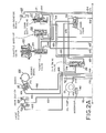
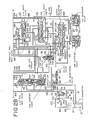
- Fig. 2A and 2B, when combined, provide a schematic view of a hydraulic control portion of the lock-up type automatic transmission;
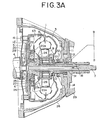
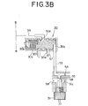
- Figs. 3A and 3B, when combined, provide a schematic sectional view showing the torque converter with the lock-up clutch, lock-up control valve and lock-up solenoid shown in Fig. 2B;
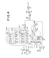
- Fig. 4 is a block diagram of a lock-up control system according to the present invention;
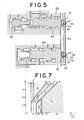
- Fig. 5 is a sectional view showing the 1-2 shift valve and 2-3 shift valve incorporating the 1-2 shift switch and 2-3 shift switch shown in Fig. 4;
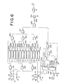
- Fig. 6 is a block diagram of a second embodiment of a lock-up control system according to the present invention; and
- Fig. 7 is a shift pattern diagram showing lock-up ranges.
- Referring to the drawings and particularly to Fig. 1, there are shown a
crank shaft 4 driven by a prime mover, an engine, a torque converter 1 having a lock-up clutch 17 which will be described later, aninput shaft 7, a front clutch 104 (a high-and-reverse clutch), a rear clutch 105 (a forward clutch), asecond brake 106, a lowreverse brake 107, a one-way brake 108, anintermediate shaft 109, a firstplanetary gear unit 110, a second planetary gear unit 111, an output shaft 112, afirst governor valve 113, asecond governor valve 114, and anoil pump 13. The torque converter 1 comprises apump impeller 3, aturbine runner 8, and astator 9, in which thepump impeller 3 is driven by thecrank shaft 4 to circulate the torque converter operation oil therein so as to transmit torque to theturbine runner 8 fixed on theinput shaft 7.. The torque is further transmitted by- theinput shaft 7 to a change-speed planetary gearing. Thestator 9 is disposed on asleeve 12 through a one-way clutch 10, the one-way clutch allowing thestator 9 to rotate in the same direction as thecrankshaft 4, that is, in the direction indicated by an arrow in Fig. 1 (this rotatipn is referred to as forward rotation hereinafter), but not allowing it to rotate in the reverse direction (this rotation is referred to as reverse rotation hereinafter). The firstplanetary gear unit 110 comprises an internallytoothed gear 117 fixed on theintermediate shaft 109, asun gear 119 fixed on a hollow transmittingshaft 118, and more than oneplanetary pinions 120 capable of performing rotation and revolution simultaneously while meshing with the internallytoothed gear 117 andsun gear 119 respectively, and aplanetary pinion carrier 121 for supporting theplanetary pinions 120 fixed on an output shaft 112, wherein the second planetary gear unit 111 comprises an internally toothed gear 122 fixed on the output shaft 112, asun gear 123 fixed on the hollow transmittingshaft 118, and more than oneplanetary pinions 124 capable of performing rotation and revolution while meshing with the internally toothed gear 122 andsun gear 123 respectively, and aplanetary pinion carrier 125 for supporting'theplanetary pinions 124. The front clutch 104 is operative to connect theinput shaft 7 to be drive by theturbine runner 8 to the hollow transmittingshaft 118 integrally rotatable with both of thesun gears drum 126, whereas therear clutch 105 is operative to connect theinput shaft 7 to the internallytoothed gear 117 of the firstplanetary gear unit 110 through theintermediate shaft 109. Thesecond brake 106 is operative to anchor bothsun gears drum 126 fixed on the hollow transmittingshaft 118, whereas the lowreverse brake 107 is operative to anchor thepinion carrier 125 of the second planetary gear unit 111. The one-way brake 108 allows forward rotation of thepinion carrier 125 but not reverse rotation thereof. The first and second governor valve assemblies 113 and 114 are operatively connected to the output shaft 112 and produce governor pressure in response to the vehicle speed. - Now, power flow paths to be established when a manual speed selector rod is set in D position (forward drive range) will be explained.
- In this case, only the
rear clutch 105, a forward clutch, is in engaged condition. The power output of the engine via the torque converter 1 is transmitted by theinput shaft 7 andrear clutch 105 to the internallytoothed gear 117 of the firstplanetary gear unit 110. This rotation of the internallytoothed gear 117 causes theplanetary gears 120 to rotate forwardly. Accordingly, thesun gear 119 rotates reversely, and, since thesun gear 123 of the second planetary gear unit 111 which is rotatable with thesun gear 119 rotates reversely, theplanetary gears 124 of the second planetary gear unit 111 rotates forwardly. The one-way brake 108 acts as a forward reaction brake to prevent thepinion carrier 125 from being rotated reversely by thesun gear 123, thus causing the forward rotation of the internally toothed gear 122 of the second planetary gear unit 111. Accordingly, the output shaft 112 which is rotatable with the internally toothed gear 122 rotates forwardly, thereby the first forward gear ratio being established. - If, in this state, the vehicle speed increases enough to cause the application of the
second brake 106, the power flow path through theinput shaft 7 andrear clutch 105 up to the internallytoothed gear 117 is the same as that for the first forward speed. Thesecond brake 106 acts as a forward reaction brake to anchor thedrum 126 for preventing the rotation of thesun gear 119. This causes theplanetary pinions 120 to rotate, revolving simultaneously, around the anchoredsun gear 119, and accordingly theplanetary pinion carrier 121 and output shaft 112, which is rotatable with thepinion carrier 121, rotate at a faster speed than in the case of the first speed although with a certain reduction ratio, thereby the second forward gear ratio being established. - If the vehicle speed further increases so as to cause the
second brake 106 to be released and, in lieu thereof, the front clutch 104 to be engaged, the power on theinput shaft 7 is transmitted partially through therear clutch 105 to the internallytoothed gear 117, while the remainder is transmitted through the front clutch 104 to thesun gear 119. Thus, the internallytoothed gear 117 andsun gear 119 are interlocked and rotate forwardly, as a unit, together with both thepinion carrier 121 and output shaft 112 at the same rotational speed, thereby the third forward gear ratio being established. In this case, the input is fed to both the front clutch 104 andrear clutch 105 and the torque increase is not carried out by the planetary gears so that none acts as a reaction brake in this state. - Nextly, the power transmission path in the case when the selector rod is positioned in R (rearward running) position is explained.
- In this case, the front clutch 104 and low-reverse-
brake 107 are engaged. The driving power transferred from the engine through the torque converter 1 is transferred from theinput shaft 7 through the front clutch 104 and thedrum 126 up to thesun gears rear planet carrier 125 is anchored by the low-reverse brake 107, the forward rotation of thesun gears - The planetary gearing arrangement illustrated in and described in connection with Fig. 1 is similar in construction to the planetary gearing arrangmenet disclosed in United States Pat. No. 2,856,794 issued to H. W. Simpson; on Oct. 21, 1958, and reference thereto may be made for a more complete description of the construction and operation of the transmission.
- Figs. 2A and 2B show a hydraulic control system of the above-described change speed transmission, which control system comprises an
oil pump 13, a linepressure regulator valve 128, apressure booster valve 129, a torque converter 1, aspeed selector valve 130, afirst governor valve 113, asecond governor valve 114, a 1-2shift valve 131, a 2-3shift valve 132, a throttlepressure reducing valve 133, a cut-down valve 134, asecond lock valve 135, a 2-3timing valve 136, a solenoid downshift valve 137, a throttle back-upvalve 138, avacuum throttle valve 139, avacuum diaphragm 140, a front clutch 104, arear clutch 105, asecond brake 106, aservo 141, a low-reverse brake 107, and oil pressure circuits. Theoil pump 13 is driven by a prime mover through thedriving shaft 14 and the pump impeller P of the torque converter 1 for drawing oil from a reservoir 142 through astrainer 143, where harmful dust is removed, during all operating conditions of the prime mover to send the oil to aline pressure circuit 144. The oil is regulated by the linepressure regulator valve 128 and the thus regulated oil is transmitted to the torque converter 1 andspeed selector valve 130. - The hydraulic control system illustrated in Figs. 2A and 2B is similar in construction to the hydraulic control system disclosed in United States Pat. No. 3,710,652, issued to T. Miyazaki, on Jan. 16, 1973, and reference may be made for a more complete description of the construction and operation of the transmission.
- The line
pressure regulator valve 128 comprises aspool 172 and a spring 173, in which, in addition to the spring 173, the throttle pressure in acircuit 165 and the line pressure in acircuit 156 act on thespool 172 via aspool 174 of thepressure booster valve 129 against the line pressure from acircuit 144 through anorifice 175 and the pressure from acircuit 176 both acting on upper areas of thespool 172. - The torque converter operating oil pressure is introduced from the
circuit 144 through the linepressure regulating valve 128 to acircuit 145 and, with apressure maintaining valve 146, the level of this pressure is maintained within a certain range. When the pressure exceeds a certain level, thepressure maintaining valve 146 opens to permit the oil into acircuit 147 toward the rear lubricating part of the power transmitting mechanism. When the lubricating oil pressure is too high, arelief valve 148 opens, resulting in a pressure drop. On the other hand, the lubricating oil is supplied from thecircuit 145 through afront lubrication valve 149, as it is open, to the front lubricating part of the power transmitting mechanism. Thespeed selector valve 130 is a manually operable liquid direction switching valve and it comprises aspool 150, "and is connected to a speed selector rod (not shown) through a linkage so that manipulating the speed selector rod into any desired one of the positions causes thespool 150 to change the passage of theline pressure circuit 144. Fig. 2B shows a condition of the speed selector valve when the spool takes up the N (neutral) position, wherein theline pressure circuit 144 is permitted to communicate with to two ports d and e. - The first and
second governor valves speed selector valve 130 assumes either D, II or I position, the oil pressure is fed from theline pressure circuit 144 to thesecond governor valve 114 through the port c of thespeed selector valve 130. If under this condition the automobile begins to move, the governor pressure regulated by thesecond governor valve 114 is supplied to acircuit 157 leading to thefirst governor valve 113, and subsequently when the vehicle speed reaches a predetermined value, thespool 177 of thefirst governor valve 113 moves to a position wherein thecircuit 157 communicates with acircuit 158, supplying the latter with the governor pressure regulated by thesecond governor valve 114. The governor pressure is also supplied to thecircuit 158, thus acting on the respective end surfaces of the 1-2shift valve 131, 2-3 shift valve and cut-downvalve 134 against the respective springs which urge these valves toward respective lower half positions illustrated in Figs. 2A and 2B. - In the oil flow passageway leading from the port c of the
speed selector valve 130 through acircuit 153, acircuit 161 and acircuit 162, up to an apply sideoil pressure chamber 169, the 1-2shift valve 131 and second lock valve 35 are separately arranged, and acircuit 152 leads from the port b of thespeed selector valve 130 to the second lock-upvalve 135. - Accordingly, if the speed selector rod is set in D position, the
spool 150 of thespeed selector valve 130 is moved to a position providing communication between theline pressure circuit 144 and ports a, b and c. From the port a, the oil pressure is transmitted through.thecircuit 151 to thesecond lock valve 135 to act on the lower end thereof for preventing the interruption of thecircuits spool 178. is pushed down, which spool is urged upwardly by aspring 179 and urged downwardly by the oil pressure transmitted thereto through thecircuit 152 from the port b, while, the oil pressure at the port a is transmitted through anorifice 166 and acircuit 167 to the 2-3shift valve 132. The oil pressure at the port c is transmitted through acircuit 153 to thesecond governor valve 114,rear clutch 105, and 1-2shift valve 131, thereby the first forward gear ratio condition of the transmission being provided. - When, under this condition, the vehicle speed increases up to a certain level the governor pressure in the
circuit 158 urges thespool 160 to the 1-2shift valve 131, which is urged to the right by thespring 159, to move to the left, for effecting an upshift from the first forward speed to the second forward speed, and, as a result, thecircuit 153 is permitted to communicate with thecircuit 161 thereby allowing the oil pressure to be transmitted through thesecond lock valve 135 to the apply sideoil pressure chamber 169 of theservo 141 through acircuit 162 to apply thesecond brake 106, thus establishing the second forward gear ratio condition. - Since the 1-2
shift valve 131 in this control system is minimized, thespool 160 highly responsive to effect movement to the left with the necessary speed, so that the vehicle speed at which the upshift is made does not move toward the higher vehicle speed side from the designed speed level. - When the vehicle speed further increases up to another certain level, the governor pressure in the
circuit 158 urges thespool 164 of the 2-3shift valve 132 to the left overcoming the spring 163, so that thecircuit 167 is permitted to communicate with thecircuit 168 directing the oil pressure, through thecircuit 168, to the release-sideoil pressure chamber 170 of theservo 141 so as to release thesecond brake 106 and also to the front clutch 104 to engage the clutch 104, thus the third forward gear ratio condition is established. - If the driver depresses the acclerator pedal down to a position causing the full opening of the throttle valve during operation with the speed selector lever in D position, an unillustrated kickdown switch is closed or rendered on to energize a downshift solenoid (not illustrated) for the
solenoid downshift valve 137. This urges the spool 190 of thesolenoid downshift valve 137 downwardly against a spring 191 from the locked position as illustrated by the right half in Fig. 2A. This movement of the spool 190 allows the kickdown circuit 180 to communicate with theline pressure circuit 144, thus allowing transmission of line pressure through thecircuits 144 and 180 to the 1-2shift valve 131 and the 2-3shift valve 132 to act same in opposed relationship with the governor pressure. If, under this condition, the vehicle is operating in the third gear ratio, thespool 164 of the 2-3 shift valve is forced to move against the governor pressure toward the right hand position viewing in Fig. 2B by the above-mentioned line pressure, thus effecting a forced downshift from the thrid gear ratio to the second gear ratio when the vehicle speed falls in a predetermined range, thus providing a sufficient amount of acceleration force. If the above-mentioned kickdown is carried out during operation in the second gear ratio, since the governor pressure is relatively low, thespool 160 of the 1-2shift valve 131 is forced to move rightwardly against the governor pressure from the left hand position. This causes a forced downshift from the second gear ratio to the first gear ratio, thus providing a sufficient amount of acceleration force to meet the relatively heavy load. - If the speed selector lever is moved to the II position (2nd forward speed fixed), the
spool 150 of thespeed selector valve 130 is moved to a position providing communication between theline pressure circuit 144 and the ports b, c and d. The oil pressure at the port b is fed to the same place as in the case of D and the oil pressure at the port c is fed to the rear clutch to engage the latter. Because, under this condition, the oil pressure does not act on the lower end of thesecond lock valve 135 and because the lower land has a larger area than the upper land, which lands form a space on thespool 178 opening to thecircuit 152, thespool 178 of thesecond lock valve 135 is pressed downwardly against the force of thespring 178 to assume a position in which thecircuit 152 is permitted to communicate with thecircuit 162, permitting the oil pressure to reach the apply sideoil pressure chamber 169 of theservo 141 so as to effect application of thesecond brake 106, thereby the second forward gear ratio condition being established. The oil pressure at the port d is transmitted through thecircuit 154 to the solenoid downshift valve 137 and throttle back-upvalve 138. Since the communication between theline pressure circuit 144 leading to thespeed selector valve 130 and the port a thereof is prevented, the oil pressure does not get through thecircuit 151 to the 2-3shift valve 132, thus neither release of thesecond brake 106 nor the application of the front clutch 104 will take place, so that an upshift to the third forward speed is prevented. As explained, thesecond lock valve 135 cooperates with thespeed selector valve 130 to lock the transmission in the second forward speed. If the speed selector lever is moved to I position (the first forward speed fixed), theline pressure circuit 144 is permitted to communicate with the ports c, d and e. The oil pressure at the port c reaches therear clutch 105 to effect clutch engagement and the oil pressure at the port d reach the same places as in the case of II, whereas the oil pressure at the port e is transmitted through thecircuit 155, 1-2shift valve 131 and thecircuit 171 to the low-reverse brake 107 so as to apply the lowreverse brake 107 which, when applied, acts as a forward reaction brake, thereby rendering the transmission in the first forward gear ratio condition. The oil pressure at the port e is applied to the left end of the 1-2shift valve assembly 131, through thecircuit 171, urging to press thespool 160 to the right in cooperation with thespring 159, thereby locking the transmission in the first forward speed once a downshift is made thereto. - In Fig..2B, the
reference numeral 100 denotes a lock-up control system according to the present invention which control system comprises a lock-upcontrol valve 30 and a lock-upsolenoid 31. - Referring to Figs. 3A and 3B, the lock-up
control valve 30, lock-upsolenoid 31 and torque converter 1 with a lock-up mechanism are specifically explained hereinafter. - If the speed selector lever is moved to the II position (2nd forward speed fixed), the
spool 150 of thespeed selector valve 130 is moved to a position providing communication between theline pressure circuit 144 and the ports b, c and d. The oil pressure at the port b is fed to the same place as in the case of D and the oil pressure at the port c is fed to the rear clutch to engage the latter. Because, under this condition, the oil pressure does not act on the lower end of thesecond lock valve 135 and because the lower land has a larger area than the upper land, which lands form a space on thespool 178 opening to thecircuit 152, thespool 178 of thesecond lock valve 135 is pressed downwardly against the force of thespring 178 to assume a position in which thecircuit 152 is permitted to communicate with thecircuit 162, permitting the oil pressure to reach the apply sideoil pressure chamber 169 of theservo 141 so as to effect application of thesecond brake 106, thereby the second forward gear ratio condition being established. The oil pressure at the port d is transmitted through thecircuit 154 to the solenoid downshift valve 137 and throttle back-upvalve 138. Since the communication between theline pressure circuit 144 leading to thespeed selector valve 130 and the port a thereof is prevented, the oil pressure does not get through thecircuit 151 to the 2-3shift valve 132, thus neither release of thesecond brake 106 nor the application of the front clutch 104 will take place, so that an upshift to the third forward speed is prevented. As explained, thesecond lock valve 135 cooperates with thespeed selector valve 130 to lock the transmission in the second forward speed. If the speed selector lever is moved to I position (the first forward speed fixed), theline pressure circuit 144 is permitted to communicate with the ports c, d and e. The oil pressure at the port c reaches therear clutch 105 to effect clutch engagement and the oil pressure at the port d reach the same places as in the case of II, whereas the oil pressure at the port e is transmitted through thecircuit 155, 1-2shift valve 131 and thecircuit 171 to the low-reverse brake 107 so as to apply the lowreverse brake 107 which, when applied, acts as a forward reaction brake, thereby rendering the transmission in the first forward gear ratio condition. The oil pressure at the port e is applied to the left end of the 1-2shift valve assembly 131, through thecircuit 171, urging to press thespool 160 to the right in cooperation with thespring 159, thereby locking the transmission in the first forward speed once a downshift is made thereto. - The
pump impeller 3 of the torque converter 1 is connected via atorque converter cover 6 with adrive plate 5, which drive plate is connected to the engine crankshaft 4. Theturbine runner 8 is splined to aninput shaft 7 with ahub 18, and further thestator 9 is connected to thesleeve 12 via the one-way clutch 10. The torque converter 1 is enclosed by aconverter housing 28 which is connected together with apump housing 14 and apump cover 11 to atransmission case 29. Thepump housing 14 and pump cover 11 cooperate to define a chamber within which saidoil pump 13 is accommodated, which pump is connected to thepump impeller 3 through ahollow shaft 52 driven by the engine. Thehollow shaft 52 jackets therein asleeve 12 to define an annularoil feed passage 50 for said operating oil, and thesleeve 12 allows theinput shaft 7 to extend therethrough and cooperate to define therebetween anoil discharge passage 51 for said operating oil. Thesleeve 12 is formed integrally with thepump cover 11. - The lock-up
mechanism 17 has the following structure. A lock-upclutch piston 20 is fit around thehub 18 in an axially slidable manner, and this lock-up clutch piston is accommodated within theconverter cover 6. The lock-upclutch piston 20 has an annular clutch facing 19 fixed to a surface thereof positioned opposite to the end wall of thetorque converter cover 6, thereby to provide an arrangement wherein when this clutch facing contacts with the end wall of theconverter cover 6, a lock-upclutch chamber 27 and atorque converter chamber 63 are defined on the opposite sides of the lock-upclutch piston 20. - The lock-up
clutch piston 20 is drivingly connected to theturbine runner 8 via a torsional damper 21. The torsional damper 21 is of the same type as that used in a dry-type clutch and the like and comprises adrive plate 23, torsional springs 24, rivets 25 and drivenplates 26. Anannular member 22 is welded to the lock-upclutch piston 20 and has itsclaws 22a drivingly engaging incutouts 23a formed through thedrive plate 23, and the drivenplate 26 is attached to theturbine runner 8. The lock-upchamber 27 communicates with a lock-uppassage 16 formed through theinput shaft 7, which lock-up passage is operatively associated with said lock-upcontrol system 100.. - The lock-up
control valve 30 is provided with aspool 30a which when taking an illustrated upper half position in Fig. 3B, permits aport 30d to communicate with aport 30e and, when taking an illustrated lower half position, permits theport 30d to communicate with adrain port 30f. Theport 30d communicates through apassage 56 with the lock-uppassage 16, theport 30e communicates through abranch passage 57 with a torque converter operatingoil supply passage 50 as shown in Fig. 2B, and thechamber 30c communicates through apassage 53 with the rearclutch pressure passage 153 as shown in Fig. 2B. - An
orifice 54 is provided in thepassage 53 at an intermediate portion, and thepassage 53 has abranch passage 55 from a location between this orifice and thechamber 30c. Thebranch passage 55 has therein anorifice 58 and communicates with adrain port 59 and is associated with the lock-upsolenoid 31 adapted to open and close thebranch passage 55. For this purpose, the lock-upsolenoid 31 has a plunger 31a which normally takes an illustrated left half position in Fig. 2B or Fig. 3B, but when thesolenoid 31 is energized, projects to assume an illustrated right half position to close thebranch passage 55. - When the.
solenoid 31 is not energized to allow the plunger 31a to open thebranch passage 55, this branch passage communicates with adrain port 59. Then,. the rear clutch pressure in thepassage 53 and directed toward thechamber 30c is discharged through adrain port 59, thus allowing the lock-upcontrol valve 30 to communicate theport 30d with theport 30e because thespool 30a is urged by aspring 30b to take the illustrated upper half position in Fig. 3B. Therefore, a torque converter interior pressure reaching thepassage 57 is supplied through theports passage 56,passage 16 to the lock-upchamber 27, thus causing the pressure within the lock-upchamber 27 to have the same pressure value as that within theconverter chamber 63. This causes the lock-upclutch piston 20 to move rightwardly from the illustrated Fig. 3A position to disengage itsclutch facing 19 from end wall of theconverter cover 6, thus releasing the direct connection between thepump impeller 3 and theturbine runner 8, allowing the torque converter 1 to transmit the power in the torque converter state. - When the lock-up
solenoid 31 is energized to cause the plunger 31a to close the branch passage-55, the rear clutch pressure is supplied through thepassage 53 to thechamber 30c, allowing the lock-upcontrol valve 30 to communicate theport 30d with thedrain port 30f because thespool 30a is moved leftwardly from the illustrated upper half position to the illustrated lower half position in Fig. 3B. This causes the lock-upchamber 27 to communicate through the lock-uppassage 16,passage 56,port 30d to adrain port 30f, causing the pressure therein to zero. Then, the lock-upclutch piston 20 is moved leftwardly as viewed in Fig. 3 by means of the torque converter interior pressure to be pressed into contact with the.end wall of thetorque converter cover 6, thus establishing a lock-up state wherein thepump impeller 3 is connected directly to theturbine runner 8. - On and off of the above-mentioned lock-up
solenoid 31 is controlled according to the present invention by an electronic circuit as shown in Fig. 4. In the Figure, 60 denotes a 1-2 shift switch, 61 denotes a 2-3 shift switch, and 62 denotes a vehicle speed sensor. As clearly shown in Fig. 5 for example, the 1-2shift switch 60 and 2-3shift switch 61 are mounted within said 1-2shift valve 131 and the 2-3shift valve 132, respectively, in such a manner that they open or close in response to the positions of therespective spools stationary contacts side plate 64 withinsulators shift valves respective leads 69 from thestationary contacts stationary contact 65 and thevalve spool 160 to form the 1-2shift switch 60 and enabling thestationary contact 66 and thevalve spool 164 to form the 2-3shift switch 61. - As will now be understood from the preceding, when the transmission is in the first gear ratio, both of the valve spools 160, 164 are in contact with the
stationary contacts shift switch 60 and the 2-3shift switch 61 to produce low level signals (L). When the transmission is in the second gear ratio, thevalve spool 160 only is in a position moved leftwardly to disengage from thestationary contact 65, thus causing the 1-2shift switch 60 to produce a high level signal (H). When the transmission is in the third gear ratio, thevalve spool 164 is also in a position moved leftwardly to disengage from thestationary contact 66, thus causing the 2-3shift switch 61 to also produce a H level signal. - The
vehicle speed sensor 62 produces an electric current which is grounded through aresistor 74 and an emitter collector of atransistor 78 when thetransistor 78 is rendered on and, when thetransistor 78 is rendered off, is grounded through theresistors resistor 74 and the collector-emitter of thetransistor 78 is closed, a voltage depending only upon theresistor 74 is produced as a vehicle speed signal V, and when the circuit passing through theresistors resistor 75. - The signals from the above-mentioned 1-2
shift switch 60 and 2-3shift switch 61 are fed to a gearratio decision circuit 201, said gear ratio decision circuit decides a corresponding gear ratio (shifted speed position) depending upon various combinations as shown in the following Table of the signals from both of the shift switches 60 and 61. a
- The gear
ratio decision circuit 201 generates a H level signal at a gate a' only during operation in the first gear ratio, and a H level signal at a gate 5' only during operation in the second gear ratio, and a H level signal at a gate c' only during operation in the third gear ratio which are subsequently fed to the respective one input terminals of the corresponding ANDgates 202 to 204. The vehicle speed signal V from thevehicle speed sensor 62 is fed to a vehiclespeed decision circuit 205, said vehicle speed decision circuit compares the vehicle speed signal V with a lock-up vehicle speed V1 for first gear ratio, with a lock-up vehicle speed V2 for second gear ratio and with a lock-up vehicle speed V3 for third gear ratio, and generate a H level signal from a gate a when V > V1, generates another H level signal also from agate 5 when V > V2, and generates still another H level signal also from a gatec when V > V3, and feeds such signals to the other input terminals of the ANDgates 202 to 204. The ANDgates 202 to 204 effect AND operation between the above-mentioned signals fed thereto so that the ANDgate 202 generates a H level signal during operation within the illustrated lock-up range A in Fig. 7, ANDgate 203 generates a H level signal during operation within the illustrated lock-up range B in Fig. 7, and ANDgate 204 generates a H level signal during operation within the illustrated lock-up range C in Fig. 7. ORgate 206 receives the outputs from these ANDgates 202 to 204 so that it generates a lock-up permission signal SL during operation within any one of the lock-up ranges A, B and C. - This H level lock-up permission signal SL is applied to the base of the
transistor 78, rendering same off, and in this state since as described before the vehicle speed signal is in fact increased from a level actually corresponding to the vehicle speed by a constant value that is determined by the resistance of theresistor 75, the actual lock-up release vehicle speeds are lowered to take values a', b', and c' as shown in Fig. 7 which are relatively lower than the lock-up vehicle speeds V1, V2 and V31 thus setting hysterisis between them. - The signal from the 1-2
shift switch 60 is fed to a 2-1downshifting detector circuit 207 and also to a 1-2upshifting detector circuit 208, wherein thecircuit 207 is in the form of an edge trigger circuit which detects a 2-1 downshifting command, viz., a fall in the signal from the 1-2shift switch 60, while, thecircuit 208 is in the form of an edge trigger circuit which detects a 1-2 upshifting command, viz., a rise in the signal from the 1-2shift switch 60. For this purpose, thecircuit 207 comprises aNOT gate 213, aresistor 210, acapacitor 211 and a NORgate 212, while, thegate 208 comprises aNOT gate 213, aresistor 214, acapacitor 215 and an ANDgate 216. If the level of the signal from the 1-2shift switch 60 falls from a H level to a L level, viz., issuance of a 2-1 downshifting command, the 2-1downshifting detector circuit 207 allows the NORgate 212 to continue to produce a H level signal (2-1 downshift signal) for a duration until charging of thecapacitor 211 is completed, viz., a time constant ofRC circuit gate 217. If the level of the signal from the 1-2shift switch 60 rises from a L level to a H level, viz., issuance of a 1-2 upshifting command, the 1-2upshifting detector circuit 208 allows the ANDgate 216 to continue to produce a H level signal (1-2 upshift signal) for a duration until the charging of thecapacitor 215 is completed, viz., a time constant of RC circuit 214,215 for feeding the H level signal to the NORgate 217. The 2-1downshifting detector circuit 207 and 1-2upshifting detector circuit 208 continue to produce L level signals, respectively, in their stable states other than the above mentioned state for feeding L level signals to the NORgate 217. - The signal from the 2-3
shift switch 61 is fed to a 3-2downshifting detector circuit 218 and a 2-3 upshifting detector circuit 219, wherein thecircuit 218 is in the form of an edge trigger circuit which detects a 3-2 downshifting command, viz., a fall in the signal from the 2-3shift switch 61, while, the circuit 219 is in the form of an edge trigger circuit which detects a 2-3 upshifting command, viz., a rise in the signal from the 2-3shift switch 61. For this purpose, thecircuit 218 is constructed in a similar manner to the 2-1downshifting circuit 207 and comprises aNOT gate 220, aresistor 221, acapacitor 222 and a NORgate 223, while, the circuit 219 is constructed in a similar manner to saidcircuit 208 and comprises aNOT gate 224, aresistor 225, acapacitor 226 and an AND gate 227. If the level of the signal from the 2-3shift switch 61 falls from a H level to a L level, viz., an issuance of a 3-2 downshifting command, the 3-2downshifting detector circuit 218 allows the NORgate 223 to continue to produce a H level signal (3-2 downshift signal) for a duration until charging of thecapacitor 222 is completed, viz., a time constant ofRC circuit gate 217. If the level of the. signal from the 2-3shift switch 61 rises from a L level to a H level, viz., an issuance of a 2-3 upshifting command, the 2-3 upshift detector circuit 219 allows the AND gate to continue to produce a H level signal (2-3 upshift signal) for a duration until charging of thecapacitor 226 is completed, viz., a time constant of RC circuit 225,226 for feeding this H level signal to the NORgate 217. The 3-2downshifting detector circuit 218 and 2-3 upshifting detector circuit 219 continue to feed L level signals to a NORgate 217. - Therefore, during normal operating state when the shift switches 60 and 61 stay in their ON or OFF states, the shifting
detector circuits gate 217 to continue to issue a H level signal toward the ANDgate 228. Accordingly, in this circumstance, the ANDgate 228 generates a H level signal or a L level signal in response to the presence or absence of the lock-up signal SL (H level). If the ANDgate 228 generates a H level signal upon reception of the lock-up permission signal sLl this generated signal is applied via abias resistor 229 to a base of atransistor 230 rendering same conductive so as to allow energization of the lock-upsolenoid 31 with a power source +V to enable the torque converter to operate in lock-up state. If the ANDgate 228 generates a L level signal when it does not receive the lock-up permission signal SL, thetransistor 230 is rendered non-conductive, so that the lock-upsolenoid 31 is deenergized so as to enable the torque converter 1 to operate in a torque converter state. It follows that the torque converter 1 is so controlled as to operate in lock-up state when in operation within ranges A, B, C as illustrated in Fig. 7, but to operate in torque converter state outside of these ranges. - However, during upshifting from the first gear ratio to the second gear ratio or from the second gear ratio to the third gear ratio or during downshifting from the third gear ratio to the second gear ratio or from second gear ratio to the first gear ratio, the
corresponding shift switch detector circuits solenoid 31 from being energized, thereby suspending the lock-up operation, with·the result that the occurrence of a great shock that otherwise would occur if the shifting takes place when the torque converter remains in the lock-up state is prevented. - According to the present invention, however, there are time constants of the RC circuits of the
shift detector circuits detector circuits - Fig. 6 shows another embodiment according to the present invention which is so designed as to modify the duration of generation of a gear shift signal in accordance with engine load (throttle opening degree in this example) because an actual gear shifting operation differs depending upon the engine load as previously explained, wherein counterparts to those illustrated in Fig. 4 are designated by like reference numerals. In this embodiment, for this purpose, an
idle switch 70 and afull throttle switch 71 are incorporated. These switches coact with the accelerator pedal, wherein theidle switch 70 is rendered ON when the depression of the accelerator pedal is within a range smaller than a predetermined value (light load range), and thefull throttle switch 71 is rendered ON when the accelerator pedal is depressed into a range greater than a predetermined value (great or heavy load range). Theswitches respective resistors 76 and 77 so that theswitch 70 detects the light load operation, including idling operation, of the engine and is closed to generate a L level signal, theswitch 71 detects the great load state of the engine operation and is closed to generate a L level signal, and when the throttle opening degree is between them, viz., the engine operation with intermediate load, both of theswitches - The signals from the
idle switch 70 andfull throttle switch 71 are fed to aNAND gate 231, an ANDgate 232 and aNAND gate 233, wherein when the engine operates with a light engine load when the depression of the accelerator pedal is smaller than the predetermined level and theidle switch 70 is closed, a L level signal from theidle switch 70 causes theNAND gate 231 to generate a H level; when the engine operates with a high or heavy load when the accelerator pedal is depressed greater than the predetermined level and thefull throttle switch 71 is closed, the L level signal from thefull throttle switch 71 causes theNAND gate 233 to generate a H level signal; and when the engine operates with intermeidte load by manipulating the accelerator pedal between these predetermined levels and both of the idle and full throttle switches 70 and 71 are open to generate H level signals, respectively, these H level signals cause the ANDgate 232 which effect AND operation between these H level signals to generate a H level signal. Viz., each of theNAND gate 231, ANDgate 232 andNAND gate 233 feeds a H level signal to a corresponding one of the ANDgates gate 231 feeds a H level signal to the corresponding ANDgate 234 in response to light load, thegate 232 feeds a H level signal to the corresponding ANDgate 235 in response the intermediate .load, and thegate 233 feeds a H level signal to the corresponding ANDgate 236 in response to high load. - In this embodiment,
edge trigger circuits detector circuit edge trigger circuits circuit 208 or 219 are also provided. Thecircuits circuit 208a as a 1-2 upshifting detector circuit, using thecircuit 218a as a 3-2 downshifting detector circuit, and using thecircuit 219a as a 2-3 upshifting detector circuit. Thecircuits circuit 207b as a 2-1 downshifting detector circuit, using thecircuit 208b as a 1-2 upshifting detector circuit, using thecircuit 218b as a 3-2 downshifting detector circuit, and using thecircuit 219b as a 2-3 upshifting detector circuit. Furthermore, thecircuits circuit 207c as a 2-1 downshifting detector circuit, using thecircuit 208c as a 1-2 upshifting detector circuit, using thecircuit 218c as a 3-2 downshifting detector circuit, and using thecircuit 219c as a 2-3 upshifting detector circuit. - The
circuits circuits shift switch 60 and respond to a fall in this signal (2-1 downshifting command) and a rise in this signal (1-2 upshifting command), wherein, upon issuance of a 2-1 downshifting command, one of thecircuits gates circuits gates circuits shift switch 61 and respond to a fall in the signal (3-2 downshifting command) and a rise in the signal (2-3 upshifting command), wherein, in accordance with kinds of gear shifting commands, upon issuance of a 3-2 downshifting command, one of thecircuits gates circuits OR gates - Accordingly, when the transmission undergoes a shifting, the OR
gates gates NAND gate 231, ANDgate 232 andNAND gate 233 and only one of the output signals from thesegates 231 to 233 takes a H level in accordance with the engine load as previously described, only one of the ANDgates gate 217 while the gear shift signal is present. Then, the NORgate 217 generates a L level signal to the ANDgate 228, as previously described, thus deenergizing the lock-upsolenoid 31 even when said lock-up permission signal SL is present so as to suspend the lock-up state, thereby preventing the occurrence of a shift shock. - According to this embodiment, therefore, the gear shifting
detector circuits - In the previously described two embodiments, a gear shift signal appears simultaneously with the occurrence of a gear shifting comand, but it is preferably to delay the occurrence of a gear shift signal because the actual gear shifting operation initiated upon expiration of a duration after the occurrence of a gear shifting command.
Claims (2)
Applications Claiming Priority (2)
| Application Number | Priority Date | Filing Date | Title |
|---|---|---|---|
| JP9163980A JPS5718852A (en) | 1980-07-07 | 1980-07-07 | Lock-up type automatic speed change gear |
| JP91639/80 | 1980-07-07 |
Publications (3)
| Publication Number | Publication Date |
|---|---|
| EP0044461A2 true EP0044461A2 (en) | 1982-01-27 |
| EP0044461A3 EP0044461A3 (en) | 1984-05-16 |
| EP0044461B1 EP0044461B1 (en) | 1988-05-04 |
Family
ID=14032093
Family Applications (1)
| Application Number | Title | Priority Date | Filing Date |
|---|---|---|---|
| EP81105264A Expired EP0044461B1 (en) | 1980-07-07 | 1981-07-07 | Lock-up control system for lock-up type automatic transmission |
Country Status (4)
| Country | Link |
|---|---|
| US (1) | US4539869A (en) |
| EP (1) | EP0044461B1 (en) |
| JP (1) | JPS5718852A (en) |
| DE (1) | DE3176728D1 (en) |
Cited By (4)
| Publication number | Priority date | Publication date | Assignee | Title |
|---|---|---|---|---|
| EP0095132A1 (en) * | 1982-05-20 | 1983-11-30 | Nissan Motor Co., Ltd. | Method and apparatus for controlling continuously variable transmission |
| DE3328548A1 (en) * | 1983-08-08 | 1985-02-21 | Kraftanlagen Ag, 6900 Heidelberg | STORAGE MATERIAL FOR HEAT TRANSFER |
| FR2552188A1 (en) * | 1983-09-21 | 1985-03-22 | Honda Motor Co Ltd | DIRECT COUPLING CLUTCH CONTROL DEVICE FOR TORQUE CONVERTER |
| EP0180209B1 (en) * | 1984-10-30 | 1991-01-02 | Nissan Motor Co., Ltd. | Creep torque and lock-up control for automatic transmission |
Families Citing this family (20)
| Publication number | Priority date | Publication date | Assignee | Title |
|---|---|---|---|---|
| JPS6049793B2 (en) * | 1981-03-30 | 1985-11-05 | 日産自動車株式会社 | Lock-up control device for lock-up automatic transmission |
| DE3470495D1 (en) * | 1983-06-01 | 1988-05-26 | Mazda Motor | Control means for vehicle automatic transmissions |
| JPS6081565A (en) * | 1983-10-07 | 1985-05-09 | Nissan Motor Co Ltd | Lock-up type automatic transmission |
| CA1230989A (en) * | 1983-11-08 | 1988-01-05 | Takashi Aoki | Control system for a direct-coupling mechanism in hydraulic power transmission means of a transmission for automotive vehicles |
| JPS60175855A (en) * | 1984-02-23 | 1985-09-10 | Nissan Motor Co Ltd | Speed-change shock lightening apparatus for automatic speed change gear |
| US4719822A (en) * | 1984-04-04 | 1988-01-19 | Toyota Jidosha Kabushiki Kaisha | Hydraulic pressure control apparatus for use in an automotive transmission |
| JPS60256676A (en) * | 1984-06-01 | 1985-12-18 | Nissan Motor Co Ltd | Lockup type automatic transmission gear |
| JPH0765670B2 (en) * | 1984-10-01 | 1995-07-19 | マツダ株式会社 | Automatic transmission control device |
| JPS62165051A (en) * | 1986-01-13 | 1987-07-21 | Toyota Motor Corp | Method for controlling automatic transmission |
| JPS62209265A (en) * | 1986-03-07 | 1987-09-14 | Aisin Seiki Co Ltd | Lockup controller for automatic transmission |
| JP2702703B2 (en) * | 1986-06-30 | 1998-01-26 | アイシン・エィ・ダブリュ株式会社 | Automatic transmission with lock-up clutch |
| JPS63169480U (en) * | 1987-04-27 | 1988-11-04 | ||
| HU206654B (en) * | 1987-10-14 | 1992-12-28 | Csepeli Autogyar | Method for ratio switching of automatic or automatized mechanical synchronous gear box at motor vehicles |
| US4953091A (en) * | 1988-10-24 | 1990-08-28 | Ford Motor Company | Automatic transmission torque converter clutch control |
| JP2825289B2 (en) * | 1989-10-16 | 1998-11-18 | マツダ株式会社 | Fluid coupling slip control device |
| JP3094747B2 (en) * | 1993-09-29 | 2000-10-03 | アイシン・エィ・ダブリュ株式会社 | Control device for automatic transmission |
| US5787379A (en) * | 1993-12-22 | 1998-07-28 | Nissan Motor Co., Ltd. | Lockup control system for automatic transmissions |
| JPH08261321A (en) * | 1995-03-27 | 1996-10-11 | Mazda Motor Corp | Controller for automatic transmission |
| KR0142459B1 (en) * | 1995-08-22 | 1998-08-01 | 전성원 | Line pressure control unit and method of hydraulic control system |
| US9056603B2 (en) * | 2012-05-01 | 2015-06-16 | GM Global Technology Operations LLC | System and method for controlling engine torque to prevent driveline bump during a downshift when a throttle valve is closed |
Citations (13)
| Publication number | Priority date | Publication date | Assignee | Title |
|---|---|---|---|---|
| US2896478A (en) * | 1954-09-07 | 1959-07-28 | Gen Motors Corp | Transmission control systems |
| US3448640A (en) * | 1967-06-30 | 1969-06-10 | Gen Motors Corp | Electrical control for automatic transmission |
| US3466950A (en) * | 1968-01-31 | 1969-09-16 | Gen Motors Corp | Automatic transmissions with shift timing valve |
| US3805640A (en) * | 1972-09-08 | 1974-04-23 | Twin Disc Inc | Electronically controlled power transmission |
| US3830258A (en) * | 1969-04-25 | 1974-08-20 | Borg Warner Ltd | Transmission control mechanism |
| US4026169A (en) * | 1974-06-29 | 1977-05-31 | Zahnradfabrik Friedrichshafen Ag | Electro-hydraulic control system for speed-changing mechanism switchable under load |
| US4027554A (en) * | 1973-07-30 | 1977-06-07 | Kabushiki Kaisha Komatsu Seisakusho | Electronic control apparatus of an automatic speed changing apparatus |
| US4100530A (en) * | 1975-12-29 | 1978-07-11 | Texas Instruments Incorporated | Controlled mechanical system |
| GB1536657A (en) * | 1975-11-14 | 1978-12-20 | Srm Hydromekanik Ab | Control system for a hydrodynamic torque converter |
| FR2422082A1 (en) * | 1978-04-04 | 1979-11-02 | Nissan Motor | TIMED LOCKOUT CONTROL SYSTEM FOR A TORQUE CONVERTER |
| FR2422083A1 (en) * | 1978-04-04 | 1979-11-02 | Nissan Motor | LOCKOUT CONTROL SYSTEM FOR A TORQUE CONVERTER |
| FR2435639A1 (en) * | 1978-09-05 | 1980-04-04 | Nissan Motor | HYDRAULIC CONTROL SYSTEM FOR HYDROKINETIC TORQUE CONVERTER |
| US4208929A (en) * | 1976-12-21 | 1980-06-24 | Deere & Company | Automatic electronic control for a power shift transmission |
Family Cites Families (19)
| Publication number | Priority date | Publication date | Assignee | Title |
|---|---|---|---|---|
| US3073179A (en) * | 1953-12-04 | 1963-01-15 | Gen Motors Corp | Torque transmitting mechanism |
| US2856794A (en) * | 1955-12-13 | 1958-10-21 | Howard W Simpson | Planetary transmission for self-propelled vehicle |
| US3710652A (en) * | 1969-05-30 | 1973-01-16 | Nissan Motor | Hydraulic control system of automatic transmission |
| JPS4843204B1 (en) * | 1970-12-21 | 1973-12-17 | ||
| US3693478A (en) * | 1971-01-06 | 1972-09-26 | Gen Motors Corp | Transmission having a converter clutch and a control |
| DE2104934A1 (en) * | 1971-02-03 | 1972-08-17 | Bosch Gmbh Robert | Control device for actuating a vehicle friction clutch |
| US3705642A (en) * | 1971-02-12 | 1972-12-12 | Gen Motors Corp | Transmission control system |
| JPS5314697B2 (en) * | 1972-09-08 | 1978-05-19 | ||
| US3857302A (en) * | 1973-06-25 | 1974-12-31 | Caterpillar Tractor Co | Transmission and speed controlled lock-up clutch |
| JPS589861B2 (en) * | 1975-04-17 | 1983-02-23 | トヨタ自動車株式会社 | Kinoseigyosouchi |
| US3985046A (en) * | 1975-06-23 | 1976-10-12 | Caterpillar Tractor Co. | Control valve for a torque converter lock-up clutch or the like |
| JPS52106066A (en) * | 1976-03-02 | 1977-09-06 | Toyota Motor Corp | Direct connected clutch controller for automatic gear reduction having a torque converter with direct connected clutch |
| US4148231A (en) * | 1977-04-25 | 1979-04-10 | Clark Equipment Company | Automatic transmission control |
| GB1587574A (en) * | 1977-11-11 | 1981-04-08 | Brown Gear Ind | Vehicles |
| ZA794292B (en) * | 1978-08-18 | 1981-03-25 | Srm Hydromekanik Ab | Hydromechanical transmissions |
| US4262335A (en) * | 1978-08-18 | 1981-04-14 | S.R.M. Hydromekanik | Vehicle transmission control system |
| JPS5825182B2 (en) * | 1978-11-07 | 1983-05-26 | アイシン・ワ−ナ−株式会社 | Direct-coupled clutch control device for automatic transmission with torque converter with direct-coupled clutch |
| JPS5569353A (en) * | 1978-11-20 | 1980-05-24 | Fuji Heavy Ind Ltd | Direct-coupled clutch operating device of fluidic torque converter |
| US4373619A (en) * | 1980-04-07 | 1983-02-15 | Grad-Line, Inc. | Transmission control system |
-
1980
- 1980-07-07 JP JP9163980A patent/JPS5718852A/en active Granted
-
1981
- 1981-07-06 US US06/280,818 patent/US4539869A/en not_active Expired - Lifetime
- 1981-07-07 DE DE8181105264T patent/DE3176728D1/en not_active Expired
- 1981-07-07 EP EP81105264A patent/EP0044461B1/en not_active Expired
Patent Citations (13)
| Publication number | Priority date | Publication date | Assignee | Title |
|---|---|---|---|---|
| US2896478A (en) * | 1954-09-07 | 1959-07-28 | Gen Motors Corp | Transmission control systems |
| US3448640A (en) * | 1967-06-30 | 1969-06-10 | Gen Motors Corp | Electrical control for automatic transmission |
| US3466950A (en) * | 1968-01-31 | 1969-09-16 | Gen Motors Corp | Automatic transmissions with shift timing valve |
| US3830258A (en) * | 1969-04-25 | 1974-08-20 | Borg Warner Ltd | Transmission control mechanism |
| US3805640A (en) * | 1972-09-08 | 1974-04-23 | Twin Disc Inc | Electronically controlled power transmission |
| US4027554A (en) * | 1973-07-30 | 1977-06-07 | Kabushiki Kaisha Komatsu Seisakusho | Electronic control apparatus of an automatic speed changing apparatus |
| US4026169A (en) * | 1974-06-29 | 1977-05-31 | Zahnradfabrik Friedrichshafen Ag | Electro-hydraulic control system for speed-changing mechanism switchable under load |
| GB1536657A (en) * | 1975-11-14 | 1978-12-20 | Srm Hydromekanik Ab | Control system for a hydrodynamic torque converter |
| US4100530A (en) * | 1975-12-29 | 1978-07-11 | Texas Instruments Incorporated | Controlled mechanical system |
| US4208929A (en) * | 1976-12-21 | 1980-06-24 | Deere & Company | Automatic electronic control for a power shift transmission |
| FR2422082A1 (en) * | 1978-04-04 | 1979-11-02 | Nissan Motor | TIMED LOCKOUT CONTROL SYSTEM FOR A TORQUE CONVERTER |
| FR2422083A1 (en) * | 1978-04-04 | 1979-11-02 | Nissan Motor | LOCKOUT CONTROL SYSTEM FOR A TORQUE CONVERTER |
| FR2435639A1 (en) * | 1978-09-05 | 1980-04-04 | Nissan Motor | HYDRAULIC CONTROL SYSTEM FOR HYDROKINETIC TORQUE CONVERTER |
Non-Patent Citations (1)
| Title |
|---|
| Automatische Automobilgetriebe,3 Stüper,Wien-New York,1965,s.333-335. * |
Cited By (5)
| Publication number | Priority date | Publication date | Assignee | Title |
|---|---|---|---|---|
| EP0095132A1 (en) * | 1982-05-20 | 1983-11-30 | Nissan Motor Co., Ltd. | Method and apparatus for controlling continuously variable transmission |
| US4526557A (en) * | 1982-05-20 | 1985-07-02 | Nissan Motor Co., Ltd. | Method and apparatus for controlling a continuously variable transmission |
| DE3328548A1 (en) * | 1983-08-08 | 1985-02-21 | Kraftanlagen Ag, 6900 Heidelberg | STORAGE MATERIAL FOR HEAT TRANSFER |
| FR2552188A1 (en) * | 1983-09-21 | 1985-03-22 | Honda Motor Co Ltd | DIRECT COUPLING CLUTCH CONTROL DEVICE FOR TORQUE CONVERTER |
| EP0180209B1 (en) * | 1984-10-30 | 1991-01-02 | Nissan Motor Co., Ltd. | Creep torque and lock-up control for automatic transmission |
Also Published As
| Publication number | Publication date |
|---|---|
| JPS6260579B2 (en) | 1987-12-17 |
| DE3176728D1 (en) | 1988-06-09 |
| JPS5718852A (en) | 1982-01-30 |
| EP0044461A3 (en) | 1984-05-16 |
| US4539869A (en) | 1985-09-10 |
| EP0044461B1 (en) | 1988-05-04 |
Similar Documents
| Publication | Publication Date | Title |
|---|---|---|
| US4457410A (en) | Lock-up control system for a lock-up type automatic transmission of an automotive vehicle having an engine | |
| US4539869A (en) | Lock-up control system for lock-up type automatic transmission | |
| US4431095A (en) | Lock-up type automatic transmission | |
| US4473882A (en) | Control method of and system for automatic transmission for automotive vehicle | |
| EP0049476B1 (en) | Lock-up control method of and system for automatic transmission for automotive vehicle having engine provided with fuel cut means | |
| US4350234A (en) | Automatic transmission system provided with a function of engine brake | |
| US4449618A (en) | Lock-up control system for lock-up type automatic transmission | |
| EP0041238B1 (en) | Control system for engine of automotive vehicle equipped with lock-up type automatic transmission | |
| US4582182A (en) | Lock-up control and method thereof | |
| US4471438A (en) | Lock-up type automatic transmission | |
| US4662249A (en) | Shift valve with an intermediate position during a 4-2 shift | |
| GB2033033A (en) | Shift points control apparatus for an automatic transmission | |
| US4573375A (en) | Control system and method for automatic transmission for automotive vehicle | |
| US4531433A (en) | Hydraulically controlled automatic transmission | |
| US3896685A (en) | Transmission control for a transmission having one drive establishing device for two independent drive functions | |
| US5069085A (en) | Shift control system for automatic power transmission with enhanced shifting transition characteristics | |
| US3546974A (en) | Transmission control system | |
| JP2829031B2 (en) | Control device for vehicle hydraulic system | |
| JPS6318052B2 (en) | ||
| JP2956970B2 (en) | Transmission control device for automatic transmission | |
| JPH0121382B2 (en) | ||
| JPS6349103B2 (en) | ||
| JPS6011265B2 (en) | automatic transmission | |
| JPH0442600Y2 (en) | ||
| JPS5932334B2 (en) | Fuel cut control device for vehicles equipped with automatic transmission |
Legal Events
| Date | Code | Title | Description |
|---|---|---|---|
| PUAI | Public reference made under article 153(3) epc to a published international application that has entered the european phase |
Free format text: ORIGINAL CODE: 0009012 |
|
| AK | Designated contracting states |
Designated state(s): DE FR GB |
|
| PUAL | Search report despatched |
Free format text: ORIGINAL CODE: 0009013 |
|
| AK | Designated contracting states |
Designated state(s): DE FR GB |
|
| RHK1 | Main classification (correction) |
Ipc: B60K 41/22 |
|
| 17P | Request for examination filed |
Effective date: 19840509 |
|
| RAP1 | Party data changed (applicant data changed or rights of an application transferred) |
Owner name: NISSAN MOTOR CO., LTD. |
|
| GRAA | (expected) grant |
Free format text: ORIGINAL CODE: 0009210 |
|
| STAA | Information on the status of an ep patent application or granted ep patent |
Free format text: STATUS: THE PATENT HAS BEEN GRANTED |
|
| AK | Designated contracting states |
Kind code of ref document: B1 Designated state(s): DE FR GB |
|
| REF | Corresponds to: |
Ref document number: 3176728 Country of ref document: DE Date of ref document: 19880609 |
|
| ET | Fr: translation filed | ||
| PLBE | No opposition filed within time limit |
Free format text: ORIGINAL CODE: 0009261 |
|
| 26N | No opposition filed | ||
| PGFP | Annual fee paid to national office [announced via postgrant information from national office to epo] |
Ref country code: DE Payment date: 20000703 Year of fee payment: 20 |
|
| PGFP | Annual fee paid to national office [announced via postgrant information from national office to epo] |
Ref country code: GB Payment date: 20000705 Year of fee payment: 20 |
|
| PGFP | Annual fee paid to national office [announced via postgrant information from national office to epo] |
Ref country code: FR Payment date: 20000711 Year of fee payment: 20 |
|
| PG25 | Lapsed in a contracting state [announced via postgrant information from national office to epo] |
Ref country code: GB Free format text: LAPSE BECAUSE OF EXPIRATION OF PROTECTION Effective date: 20010706 |
|
| REG | Reference to a national code |
Ref country code: GB Ref legal event code: PE20 Effective date: 20010706 |