EP0045404B1 - Vorrichtung zum Bereitstellen von Atemgas - Google Patents
Vorrichtung zum Bereitstellen von Atemgas Download PDFInfo
- Publication number
- EP0045404B1 EP0045404B1 EP81105477A EP81105477A EP0045404B1 EP 0045404 B1 EP0045404 B1 EP 0045404B1 EP 81105477 A EP81105477 A EP 81105477A EP 81105477 A EP81105477 A EP 81105477A EP 0045404 B1 EP0045404 B1 EP 0045404B1
- Authority
- EP
- European Patent Office
- Prior art keywords
- storage container
- breathing gas
- adsorbers
- respiratory gas
- emergency storage
- Prior art date
- Legal status (The legal status is an assumption and is not a legal conclusion. Google has not performed a legal analysis and makes no representation as to the accuracy of the status listed.)
- Expired
Links
- 230000029058 respiratory gaseous exchange Effects 0.000 title description 45
- 239000007789 gas Substances 0.000 claims description 61
- QVGXLLKOCUKJST-UHFFFAOYSA-N atomic oxygen Chemical compound [O] QVGXLLKOCUKJST-UHFFFAOYSA-N 0.000 claims description 22
- 239000001301 oxygen Substances 0.000 claims description 22
- 229910052760 oxygen Inorganic materials 0.000 claims description 22
- 230000000241 respiratory effect Effects 0.000 claims description 13
- 239000003463 adsorbent Substances 0.000 claims description 7
- 238000001179 sorption measurement Methods 0.000 description 17
- IJGRMHOSHXDMSA-UHFFFAOYSA-N Atomic nitrogen Chemical compound N#N IJGRMHOSHXDMSA-UHFFFAOYSA-N 0.000 description 8
- 238000000034 method Methods 0.000 description 6
- 239000002808 molecular sieve Substances 0.000 description 5
- URGAHOPLAPQHLN-UHFFFAOYSA-N sodium aluminosilicate Chemical compound [Na+].[Al+3].[O-][Si]([O-])=O.[O-][Si]([O-])=O URGAHOPLAPQHLN-UHFFFAOYSA-N 0.000 description 5
- 229910052757 nitrogen Inorganic materials 0.000 description 4
- 238000003795 desorption Methods 0.000 description 3
- 238000010926 purge Methods 0.000 description 3
- 230000008929 regeneration Effects 0.000 description 3
- 238000011069 regeneration method Methods 0.000 description 3
- 238000004378 air conditioning Methods 0.000 description 2
- 230000007423 decrease Effects 0.000 description 2
- 238000011010 flushing procedure Methods 0.000 description 2
- 239000007788 liquid Substances 0.000 description 2
- 238000012423 maintenance Methods 0.000 description 2
- 229910000831 Steel Inorganic materials 0.000 description 1
- 239000003795 chemical substances by application Substances 0.000 description 1
- 239000000356 contaminant Substances 0.000 description 1
- 230000003247 decreasing effect Effects 0.000 description 1
- 239000000945 filler Substances 0.000 description 1
- 238000002309 gasification Methods 0.000 description 1
- 238000009434 installation Methods 0.000 description 1
- 210000004072 lung Anatomy 0.000 description 1
- 210000003739 neck Anatomy 0.000 description 1
- 239000002245 particle Substances 0.000 description 1
- 230000000717 retained effect Effects 0.000 description 1
- 239000007787 solid Substances 0.000 description 1
- 125000006850 spacer group Chemical group 0.000 description 1
- 239000010959 steel Substances 0.000 description 1
Images

Classifications
-
- B—PERFORMING OPERATIONS; TRANSPORTING
- B01—PHYSICAL OR CHEMICAL PROCESSES OR APPARATUS IN GENERAL
- B01D—SEPARATION
- B01D53/00—Separation of gases or vapours; Recovering vapours of volatile solvents from gases; Chemical or biological purification of waste gases, e.g. engine exhaust gases, smoke, fumes, flue gases, aerosols
- B01D53/02—Separation of gases or vapours; Recovering vapours of volatile solvents from gases; Chemical or biological purification of waste gases, e.g. engine exhaust gases, smoke, fumes, flue gases, aerosols by adsorption, e.g. preparative gas chromatography
- B01D53/04—Separation of gases or vapours; Recovering vapours of volatile solvents from gases; Chemical or biological purification of waste gases, e.g. engine exhaust gases, smoke, fumes, flue gases, aerosols by adsorption, e.g. preparative gas chromatography with stationary adsorbents
- B01D53/047—Pressure swing adsorption
- B01D53/053—Pressure swing adsorption with storage or buffer vessel
-
- A—HUMAN NECESSITIES
- A62—LIFE-SAVING; FIRE-FIGHTING
- A62B—DEVICES, APPARATUS OR METHODS FOR LIFE-SAVING
- A62B7/00—Respiratory apparatus
- A62B7/14—Respiratory apparatus for high-altitude aircraft
-
- B—PERFORMING OPERATIONS; TRANSPORTING
- B01—PHYSICAL OR CHEMICAL PROCESSES OR APPARATUS IN GENERAL
- B01D—SEPARATION
- B01D53/00—Separation of gases or vapours; Recovering vapours of volatile solvents from gases; Chemical or biological purification of waste gases, e.g. engine exhaust gases, smoke, fumes, flue gases, aerosols
- B01D53/02—Separation of gases or vapours; Recovering vapours of volatile solvents from gases; Chemical or biological purification of waste gases, e.g. engine exhaust gases, smoke, fumes, flue gases, aerosols by adsorption, e.g. preparative gas chromatography
- B01D53/04—Separation of gases or vapours; Recovering vapours of volatile solvents from gases; Chemical or biological purification of waste gases, e.g. engine exhaust gases, smoke, fumes, flue gases, aerosols by adsorption, e.g. preparative gas chromatography with stationary adsorbents
- B01D53/0407—Constructional details of adsorbing systems
-
- B—PERFORMING OPERATIONS; TRANSPORTING
- B01—PHYSICAL OR CHEMICAL PROCESSES OR APPARATUS IN GENERAL
- B01D—SEPARATION
- B01D2259/00—Type of treatment
- B01D2259/40—Further details for adsorption processes and devices
- B01D2259/40003—Methods relating to valve switching
- B01D2259/40005—Methods relating to valve switching using rotary valves
-
- B—PERFORMING OPERATIONS; TRANSPORTING
- B01—PHYSICAL OR CHEMICAL PROCESSES OR APPARATUS IN GENERAL
- B01D—SEPARATION
- B01D2259/00—Type of treatment
- B01D2259/40—Further details for adsorption processes and devices
- B01D2259/403—Further details for adsorption processes and devices using three beds
-
- B—PERFORMING OPERATIONS; TRANSPORTING
- B01—PHYSICAL OR CHEMICAL PROCESSES OR APPARATUS IN GENERAL
- B01D—SEPARATION
- B01D2259/00—Type of treatment
- B01D2259/40—Further details for adsorption processes and devices
- B01D2259/406—Further details for adsorption processes and devices using more than four beds
-
- B—PERFORMING OPERATIONS; TRANSPORTING
- B01—PHYSICAL OR CHEMICAL PROCESSES OR APPARATUS IN GENERAL
- B01D—SEPARATION
- B01D2259/00—Type of treatment
- B01D2259/45—Gas separation or purification devices adapted for specific applications
- B01D2259/4533—Gas separation or purification devices adapted for specific applications for medical purposes
-
- B—PERFORMING OPERATIONS; TRANSPORTING
- B01—PHYSICAL OR CHEMICAL PROCESSES OR APPARATUS IN GENERAL
- B01D—SEPARATION
- B01D2259/00—Type of treatment
- B01D2259/45—Gas separation or purification devices adapted for specific applications
- B01D2259/4566—Gas separation or purification devices adapted for specific applications for use in transportation means
- B01D2259/4575—Gas separation or purification devices adapted for specific applications for use in transportation means in aeroplanes or space ships
-
- B—PERFORMING OPERATIONS; TRANSPORTING
- B01—PHYSICAL OR CHEMICAL PROCESSES OR APPARATUS IN GENERAL
- B01D—SEPARATION
- B01D53/00—Separation of gases or vapours; Recovering vapours of volatile solvents from gases; Chemical or biological purification of waste gases, e.g. engine exhaust gases, smoke, fumes, flue gases, aerosols
- B01D53/02—Separation of gases or vapours; Recovering vapours of volatile solvents from gases; Chemical or biological purification of waste gases, e.g. engine exhaust gases, smoke, fumes, flue gases, aerosols by adsorption, e.g. preparative gas chromatography
- B01D53/04—Separation of gases or vapours; Recovering vapours of volatile solvents from gases; Chemical or biological purification of waste gases, e.g. engine exhaust gases, smoke, fumes, flue gases, aerosols by adsorption, e.g. preparative gas chromatography with stationary adsorbents
- B01D53/047—Pressure swing adsorption
Definitions
- the invention relates to a device for providing breathing gas for occupants of pressure-controlled cabins in aircraft by enriching oxygen in air in a breathing gas generator having a plurality of adsorbers, which is preceded by a filter on the inlet side and which is connected on the outlet side to a breathing gas outlet line.
- a device is known from US Pat. No. 3,922,149 in which a respiratory gas demand regulator 48 with a breathing mask is connected to the respiratory gas outlet line 32, 40 for the individual supply of persons with respiratory gas, an emergency reservoir 64 being provided via a line 68 (or 51) (or 14) is connected.
- An emergency supply of oxygen-rich breathing gas in the storage container 14 that can be used in the event of process interruptions is generated with the aid of the same adsorber 24, with which the oxygen in the air is enriched.
- the device is operated so that air passes through a valve 12 into the container 24, in which the individual air components are adsorbed in different proportions, oxygen least.
- the treated, oxygen-enriched gas is fed to the reservoir 14 and the breathing mask under increased pressure.
- the pressure in the container 14 rises and the valve 12 closes more and more, so that less and less air gets into the container 24.
- the gas flowing out of the container 24 has a decreasing 0 2 concentration.
- the yield of the container 24 decreases, the yield of the reservoir 14 increases, with the result that the flight crew is supplied with a concentration of 0 2 in the enriched air, which corresponds to the sea level.
- the flight crew can receive air from the storage container 14 and additionally from the emergency storage container 64 for a short time.
- a device of the type mentioned which has a filter 4, a breathing gas generator 5 consisting of several adsorbers, a breathing gas outlet line 7, a buffer tank 8 and a control valve 12 with a subsequent breathing mask 14.
- compressed air is passed through the adsorbers and the 0 2 concentration is increased by preferential adsorption of nitrogen on a suitable adsorbent.
- the amount of gas flowing through the adsorbers, the cycle time, the adsorption pressure and the ratio of adsorption to desorption pressure are controlled in order to adjust the 0 2 concentration so that it increases with increasing altitude while at the same time the amount of breathing gas (expressed in normal liters) decreases .
- the invention is therefore based on the object of providing a simplified device for providing breathing gas with an emergency storage container, with which the disadvantages mentioned are overcome.
- an emergency storage container is connected to the breathing gas outlet line via a branch line
- the adsorbers of the breathing gas generator are arranged within the emergency storage container
- the emergency storage container is charged with an adsorbent for oxygen
- the breathing gas demand regulator is arranged with a breathing mask and the breathing gas demand regulator is connected to the emergency storage container via a line.
- the device according to the invention generates an emergency supply of breathing gas from air from the same adsorbers that also provide the normal breathing gas.
- the adsorbers of the breathing gas generator are arranged inside the emergency storage container. This saves space and the installation in the aircraft is made easier by the compact system.
- the device according to the invention also eliminates the previous maintenance of the emergency supply, including the special logistics. It is also no longer necessary to supply the floor to steel bottles, for example.
- the adsorbers can be operated in pressure changes or temperature changes, it being unimportant which purge gases and desorbents are used and whether the enriched gas is obtained as product gas or desorbate. Nevertheless, pressure swing processes are advantageous, since they essentially run at a constant temperature, are therefore very cheap in terms of energy and also make it possible to switch the adsorbers quickly.
- the adsorption phase is followed by a regeneration phase (pressure release and flushing) and one out of or multiple pressure build-up phase.
- the emergency storage container is preferably charged with an adsorbent for oxygen, for example a zeolitic molecular sieve of type 5A, whereby a multiple, usually three to four times the amount of breathing gas can be stored.
- an adsorbent for oxygen for example a zeolitic molecular sieve of type 5A, whereby a multiple, usually three to four times the amount of breathing gas can be stored.
- the space remaining between the outer walls of the adsorbers and the wall of the emergency storage container is advantageously charged with the adsorbent for oxygen.
- FIGS. 1 and 2 show the device only schematically, which is why the adsorbers have been shown outside the emergency storage container.
- compressed air which is kept constant at 20 ° C, for example in an air conditioning system not shown, passes through a line 1 and a control valve 2, which keeps the air flow at approx. 10 bar, into a filter 3 existing contaminants, such as liquid droplets or solid particles, are retained.
- the air pretreated in this way flows into a breathing gas generator 4, for example an adsorption device with three switchable adsorbers, which are operated in the pressure swing method in accordance with the previously described method.
- the period in the present case is 12 seconds.
- the desorption and purge gas is drawn off via a line 5.
- the oxygen-enriched breathing gas passes through a line 6 into a breathing gas demand regulator 7. This is normally switched so that the breathing gas gets directly into a breathing mask 8 and into the lungs of the person concerned when he breathes in.
- breathing gas passes from the emergency storage container 40 via a line 16 into the breathing gas demand regulator 7, which now blocks line 6, and thus into the breathing mask 8.
- FIG. 2 shows an embodiment of a cyclically operating adsorber device in which it is particularly easy to fill up the emergency supply.
- adsorber A1 delivers the product
- adsorber A2 is regenerated
- adsorber A3 is in the build-up of pressure.
- Air compressed to 10 bar (e.g. 200 NI / min.) Reaches the adsorber A1 via the opened valve 11. There, for example from a zeolitic molecular sieve 5A, nitrogen is preferably adsorbed over oxygen. The adsorber is charged with 2.5 1 molecular sieve.
- the most oxygen-rich gas is fed into the emergency supply 40 via the opened valves 15 and 10. Then the valves 15 and 10 are closed again and normal breathing gas passes through the valve 12 and line 6 to the non-illustrated breathing gas demand regulator during the second adsorption phase.
- valves 11 and 12 close, and air passes through valve 31 to adsorber A3.
- the valves 15 and 23 are opened to equalize the pressure between the adsorbers A1 and A2.
- valves 15 and 23 close again and valve 14 opens, i. H. the adsorber A1 is regenerated.
- the adsorber A1 is regenerated.
- residual gas flows out via valve 14, and for better desorption, part of the breathing gas from adsorber A3 is used via valves 35 and 15 to purge adsorber A1 and is likewise drawn off via valve 14.
- valve 14 closes and the regeneration phase is complete.
- valves 35 and 13 close again.
- Valve 11 opens and compressed air enters adsorber A1 to build up the pressure up to the adsorption pressure.
- the valves 15 and 10 are then open again, so that oxygen-rich gas can get into the emergency storage container 40, while in the second adsorption phase, the valves 15 and 10 are closed and valve 12 is open and breathing gas via valve 12 and line 6 is conducted etc.
- adsorber A2 is in the regeneration phase, which consists of pressure relief via valve 24 and flushing via valves 15 and 25, while at the same time in adsorber A3 Pressure build-up takes place in two stages, as described above.
- breathing gas can be withdrawn from the emergency reservoir 40 via line 16.
- the consumption of breathing gas under normal conditions on the ground is 20 NI / min per man, which corresponds to 12 NI / min per man at an altitude of 4572 m (15,000 feet). Assuming that the emergency supply should last 10 minutes, this means that 120 NI must be available. However, these are pressed into the emergency storage container at a pressure of 10 bar, so that it only has to take up 12 liters. If the emergency storage container is also filled with a zeolitic molecular sieve, the volume of the emergency storage container is reduced to approximately 3 I.
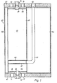
- Fig. 3 shows the emergency storage container 40, in which the three adsorbers are installed in section 111-111 of FIG. 4, so that only adsorber A1 is visible. This is welded between the top and bottom plates 41 and 42, respectively.
- the two adsorption spaces 43 and 44 are each delimited at the top and by sieve plates 45/46 and 47/48 and provided with filler necks 49 and 50. Both sockets are closed with screw plugs 51 and 52, which also serve as spacers for the upper and lower sieve plates 45 and 48, respectively.
- adsorber A1 If adsorber A1 is in the adsorption phase, the air to be separated flows in via valve 11 and the product flows out via valve 12 according to FIG. 2. After the end of the adsorption phase, pressure equalization with the adsorber A3 (not shown in FIG. 3) also takes place via valve 13 and line 17 as shown in FIG. 2. The sieve trays 46 and 47 connected to line 17, which allow gas exchange to the adsorption spaces 43 and 44, serve for this purpose. After pressure equalization, valve 13 closes and residual gas is drawn off via valve 14.
- the emergency supply of breathing gas is taken up by the intermediate space 54 remaining between the wall 53 of the container and the adsorbers.
- This intermediate space 54 can advantageously be charged with an oxygen adsorbing agent.
- the oxygen-rich respiratory gas enters space 54 through valve 10, not shown in FIG. 3, and a line, also not shown in this figure, which is located between valves 15 and 10.
- the emergency supply is removed via line 16, which in turn is shown in FIG. 2.
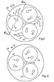
- FIG. 4 shows the top view of the emergency storage container 40, from which the three adsorbers A1, A2 and A3 are installed.
- the corresponding valves and pressure compensation tubes are shown.
- the valves can be arranged individually as shown or a rotary valve.
- FIG. 5 shows the top view of the same emergency storage container 40 from below.
- the corresponding valves and also the line 16 for removing the breathing gas can also be seen here.
Landscapes
- Chemical & Material Sciences (AREA)
- Engineering & Computer Science (AREA)
- Analytical Chemistry (AREA)
- General Chemical & Material Sciences (AREA)
- Oil, Petroleum & Natural Gas (AREA)
- Chemical Kinetics & Catalysis (AREA)
- Health & Medical Sciences (AREA)
- Pulmonology (AREA)
- General Health & Medical Sciences (AREA)
- Business, Economics & Management (AREA)
- Emergency Management (AREA)
- Respiratory Apparatuses And Protective Means (AREA)
- Separation Of Gases By Adsorption (AREA)
Description
- Die Erfindung betrifft eine Vorrichtung zum Bereitstellen von Atemgas für Insassen von druckgeregelten Kabinen in Flugzeugen durch Anreicherung von Sauerstoff in Luft in einem mehrere Adsorber aufweisenden Atemgasgenerator, dem eintrittsseitig ein Filter vorgeschaltet und der austrittsseitig mit einer Atemgasauslaßleitung verbunden ist.
- Aus der US-A-3 922 149 ist eine Vorrichtung bekannt, bei der bei der Einzelversorgung von Personen mit Atemgas in die Atemgasauslaßleitung 32, 40 ein Atemgasbedarfsregler 48 mit einer Atemmaske geschaltet ist, wobei über eine Leitung 68 (oder 51) ein Notvorratsbehälter 64 (oder 14) angeschlossen ist. Ein bei eventuellen Verfahrensunterbrechungen verwendbarer Notvorrat an sauerstoffreichem Atemgas im Vorratsbehälter 14 wird mit Hilfe desselben Adsorbers 24 erzeugt, mit dem der Sauerstoff in der Luft angereichert wird. Die Vorrichtung wird dabei so betrieben, daß Luft über ein Ventil 12 in den Behälter 24 gelangt, in dem die einzelnen Luftbestandteile zu unterschiedlichen Anteilen adsorbiert werden, Sauerstoff am wenigsten. Das behandelte, mit Sauerstoff angereicherte Gas wird unter erhöhtem Druck dem Vorratsbehälter 14 zugeführt und der Atemmaske. Bei andauernder Adsorption steigt der Druck in dem Behälter 14 an und Ventil 12 schließt immer mehr, so daß immer weniger Luft in den Behälter 24 gelangt. Als Fogle davon weist das aus dem Behälter 24 ausströmende Gas eine abnehmende 02-Konzentration auf. Gleichzeitig, während der Ertrag des Behälters 24 abnimmt, steigt der Ertrag des Vorratsbehälters 14 mit dem Ergebnis, daß das Flugpersonal mit einer 02-Konzentration in der angereicherten Luft versorgt wird, die dem Meeresspiegel äquivalent entspricht. Bei Verfahrensunterbrechungen kann das Flugpersonal für kurze Zeit Luft aus dem Vorratsbehälter 14 und zusätzlich aus dem Notvorratsbehälter 64 erhalten.
- Aus der DE-A-2 837 281 ist eine Vorrichtung der eingangs genannten Art bekannt, die ein Filter 4, einen aus mehreren Adsorbern bestehenden Atemgasgenerator 5, eine Atemgasauslaßleitung 7, einen Pufferbehälter 8 sowie ein Regelventil 12 mit nachfolgender Atemmaske 14 aufweist. Zum Betreiben dieser Vorrichtung wird komprimierte Luft durch die Adsorber geleitet und so die 02-Konzentration durch bevorzugte Adsorption von Stickstoff an einem geeigneten Adsorptionsmittel erhöht. Die Menge des die Adsorber durchströmenden Gases, die Taktzeit, der Adsorptionsdruck und das Verhältnis von Adsorptions- zu Desorptionsdruck wird kontrolliert, um die 02-Konzentration so einzustellen, daß sie mit steigender Flughöhe zunimmt, während gleichzeitig die Atemgasmenge (in Normallitern ausgedrückt) abnimmt.
- Zur Überbrückung von Ausfällen des Atemgasversorgungsysstems (wie Ausfall der Luftversorgung beispielsweise durch Abschalten der Klimaanlage oder plötzlichen Druckabfall in der Kabine durch ein Leck) ist bei diesem System ein Notvorrat an sogenanntem Höhenatmungssauerstoff nötig, der entweder aus Druckflaschen oder aus der Vergasung eines Flüssigvorrates stammt und 99,5% Sauerstoff enthält. Diese Notvorratsbehälter wie auch der Notvorratsbehälter 64 gemäß US-A-3 922 149 nehmen jedoch einen, insbesondere für die engen Flugkabinen von militärischen Maschinen, verhältnismäßig großen Raum ein. Außerdem benötigen alle diese Notversorgungssysteme eine gesonderte Logistik und Wartung.
- Der Erfindung liegt daher die Aufgabe zugrunde, eine vereinfachte Vorrichtung zum Bereitstellen von Atemgas mit einem Notvorratsbehälter zur Verfügung zu stellen, mit der die erwähnten Nachteile überwunden werden.
- Diese Aufgabe wird bei einer Vorrichtung der eingangs genannten Art erfindungsgemäß dadurch gelöst, daß an die Atemgasauslaßleitung über eine Stichleitung ein Notvorratsbehälter angeschlossen ist, die Adsorber des Atemgasgenerators innerhalb des Notvorratsbehälters angeordnet sind, der Notvorratsbehälter mit einem Adsorptionsmittel für Sauerstoff beschickt ist, in der Atemgasauslaßleitung ein Atemgasbedarfsregler mit einer Atemmaske angeordnet ist und der Atemgasbedarfsregler über eine Leitung mit dem Notvorratsbehälter verbunden ist.
- Ähnlich wie bei dem Verfahren der US-A-3 922 149 wird mit der erfindungsgemäßen Vorrichtung ein Notvorrat an Atemgas von denselben Adsorbern aus Luft erzeugt, die auch das normale Atemgas bereitstellen. Im Gegensatz zu der aus der US-A-3 922 149 bekannten Vorrichtung sind jedoch die Adsorber des Atemgasgenerators innerhalb des Notvorratsbehälters angeordnet. Hierdurch wird Platz eingespart und der Einbau im Flugzeug durch die kompakte Anlage erleichtert. Durch die erfindungsgemäße Vorrichtung entfällt überdies die bisherige Wartung des Notvorrates einschließlich der besonderen Logistik. Es ist auch keine Bodenversorgung über beispielsweise Stahlflaschen mehr nötig.
- Der Atemgasgenerator enthält beispielsweise drei umschaltbare, jeweils mit einem Adsorptionsmittel für Sauerstoff oder Stickstoff, vorzugsweise Stickstoff, z. B. mit einem zeolithischen Molekularsieb, gefüllte Adsorber. Die Adsorber können im Druckwechsel oder im Temperaturwechsel betrieben werden, wobei es unwichtig ist, welche Spülgase und Desorptionsmittel verwendet werden und ob das angereicherte Gas als Produktgas oder Desorbat erhalten wird. Dennoch bieten sich vorteilhaft Druckwechselverfahren an, da diese im wesentlichen bei gleichbleibender Temperatur ablaufen, somit energetisch sehr günstig sind und außerdem ein schnelles Umschalten der Adsorber möglich machen. Bei Druckwechselbetrieb folgt der Adsorptionsphase eine Regenerierphase (Druckentspannung und Spülung) und eine aus einer oder mehreren Druckaufbaustufen bestehene Druckaufbauphase.
- Der Notvorratsbehälter ist bevorzugt mit einem Adsorptionsmittel für Sauerstoff, beispielsweise einem zeolithischen Molekularsieb vom Typ 5A beschickt, wodurch sich eine vielfache, in der Regel drei- bis vierfache Menge an Atemgas speichern läßt.
- Mit Vorteil ist dabei der zwischen den Außenwandungen der Adsorber und der Wandung des Notvorratsbehälters verbliebene Zwischenraum mit dem Adsorptionsmittel für Sauerstoff beschickt.
- Die Wirkungsweise der erfindungsgemäßen Vorrichtung soll anhand eines Ausführungsbeispieles mit Hilfe von fünf Figuren verdeutlicht werden. Die Figuren 1 und 2 zeigen dabei zum besseren Verständnis die Vorrichtung lediglich schematisch, weshalb die Adsorber außerhalb des Notvorratsbehälters dargestellt worden sind.
- Es zeigt
- Fig. 1 ein Schema der Vorrichtung,
- Fig. 2 eine schematisch dargestellte Anlage mit drei Adsorbern,
- Fig. 3 einen Längsschnitt durch einen Notvorratsbehälter mit drei eingebauten Adsorbern,
- Fig. 4 eine Draufsicht auf den Notvorratsbehälter mit Adsorbern der Fig. 3 von oben und
- Fig. 5 eine Draufsicht auf den Notvorratsbehälter mit Adsorbern der Fig. 3 von unten.
- In Fig. 1 gelangt komprimierte Luft, die beispielsweise in einer nicht eingezeichneten Klimaanlage konstant auf 20°C gehalten wird, über eine Leitung 1 und ein Regelventil 2, das den Luftstrom auf ca. 10 bar hält, in einen Filter 3. Dort werden eventuell vorhandene Verunreinigungen, wie Flüssigkeitströpfchen oder feste Teilchen, zurückgehalten. Die so vorbehandelte Luft strömt in einen Atemgasgenerator 4 ein, beispielsweise eine Adsorptionsvorrichtung mit drei umschaltbaren Adsorbern, die im Druckwechselverfahren entsprechend dem zuvor beschriebenen Verfahren betrieben werden. Die Periodendauer beträgt im vorliegenden Fall 12 sec. Das Desorptions- und Spülgas wird über eine Leitung 5 abgezogen. Das mit Sauerstoff angereicherte Atemgas gelangt über eine Leitung 6 in einen Atemgasbedarfsregler 7. Dieser ist im Normalfall so geschaltet, daß das Atemgas direkt in eine Atemmaske 8 und beim Einatmen der betreffenden Person in deren Lungen gelangt.
- Der Notvorrat an Atemgas, der z. B. aus 95%igem Sauerstoff besteht, wird nun auf folgende Weise erzeugt:
- Bei erhöhter Triebwerksleistung gelangt die aufzuarbeitende Luft unter größerem Druck in die Adsorber, so daß in diesen ebenfalls ein größerer Druck herrscht und ein Atemgas mit erhöhtem Sauerstoffanteil produziert wird, das für den Notvorrat geeignet ist. Das Atemgas tritt über eine Leitung 6 aus dem Atemgasgenerator 4 aus und wird, wie beschrieben, der Atemmaske 8 zugeführt. Ein Teil des Atemgases wird jedoch von der Leitung 6 über eine Stichleitung 9 abgezweigt und gelangt über ein Füllventil 10 in den Notvorratsbehälter 40. Das Füllventil 10 schließt wieder, wenn der Notvorratsbehälter 40 gefüllt ist.
- Bei Betriebsunterbrechungen gelangt Atemgas aus dem Notvorratsbehälter 40 über eine Leitung 16 in den Atemgasbedarfsregler 7, der jetzt Leitung 6 sperrt, und damit in die Atemmaske 8.
- Fig. 2 zeigt eine Ausführung einer zyklisch arbeitenden Adsorbervorrichtung, bei der es besonders einfach ist, den Notvorrat aufzufüllen. Dabei soll folgende Anfangskonstellation gelten: Adsorber A1 liefert das Produkt, Adsorber A2 wird regeneriert und Adsorber A3 befindet sich im Druckaufbau.
- Auf 10 bar komprimierte Luft (z. B. 200 NI/ min.) gelangt über das geöffnete Ventil 11 in den Adsorber A1. Dort wird, beispielsweise von einem zeolithischen Molekularsieb 5A, Stickstoff bevorzugt vor Sauerstoff adsorbiert. Der Adsorber ist mit 2,5 1 Molekularsieb beschickt.
- Während der ersten Adsorptionsphasen in Adsorber A1 wird über die geöffneten Ventile 15 und 10 sauerstoffreichstes Gas in den Notvorrat 40 geleitet. Dann werden die Ventile 15 und 10 wieder geschlossen und normales Atemgas gelangt während der zweiten Adsorptionsphase über Ventil 12 und Leitung 6 zum nichteingezeichneten Atemgasbedarfsregler.
- Nach Abschluß der Adsorptionsphase in Adsorber A1 schließen die Ventile 11 und 12, und Luft gelangt über Ventil 31 auf Adsorber A3. Gleichzeitig werden die Ventile 15 und 23 zum Druckausgleich zwischen den Adsorbern A1 und A2 geöffnet.
- Nach Abschluß des Druckausgleiches, der nicht vollständig sein muß, schließen die Ventile 15 und 23 wieder und Ventil 14 öffnet, d. h. der Adsorber A1 wird regeneriert. Dazu strömt über Ventil 14 Restgas ab, und zur besseren Desorption wird ein Teil des Atemgases aus Adsorber A3 über die Ventile 35 und 15 zum Spülen von Adsorber A1 verwendet und ebenfalls über Ventil 14 abgezogen. Nach Erreichen des tiefsten Druckniveaus in Adsorber A1 schließt Ventil 14 und die Regenerierphase ist abgeschlossen.
- Nun findet über die geöffneten Ventile 35 und 13 Druckausgleich mit Adsorber A3 statt. Nach Beendigung des Druckausgleichs schließen die Ventile 35 und 13 wieder. Ventil 11 öffnet, und komprimierte Luft gelangt in Adsorber A1, um dort den Druck bis zum Adsorptionsdruck aufzubauen. In der ersten Adsorptionsphase sind dann wieder die Ventile 15 und 10 offen, so daß sauerstoffreiches Gas in den Notvorratsbehälter 40 gelangen kann, während in der zweiten Adsorptionsphase die Ventile 15 und 10 zu sind und Ventil 12 offen ist und Atemgas über Ventil 12 und Leitung 6 geleitet wird usw.
- Wärhend der Zeit der Adsorptionsphase in Adsorber A1 befindet sich Adsorber A2 in der Regenerierphase, die aus Druckablassen über Ventil 24 und Spülen über die Ventile 15 und 25 besteht, während gleichzeitig in Adsorber A3 der Druckaufbau in zwei Stufen, wie oben beschrieben, erfolgt.
- Im Bedarfsfall kann dem Notvorratsbehälter 40 über Leitung 16 Atemgas entnommen werden.
- Erfahrungsgemäß liegt der Verbrauch an Atemgas unter Normalbedingungen am Boden bei 20 NI/min pro Mann, was 12 NI/min pro Mann in einer Höhe von 4572 m (15 000 Fuß) entspricht. Unter der Annahme, daß der Notvorrat 10 Minuten ausreichen soll, bedeutet das, daß 120 NI zur Verfügung stehen müssen. Diese werden aber unter einem Druck von 10 bar in den Notvorratsbehälter gepreßt, so daß dieser nur 12 I aufzunehmen braucht. Ist der Notvorratsbehälter außerdem mit einem zeolithischen Molekularsieb gefüllt, so reduziert sich das Volumen des Notvorratsbehälters auf ca. 3 I.
- Fig. 3 zeigt den Notvorratsbehälter 40, in dem die drei Adsorber eingebaut sind im Schnitt 111-111 gemäß Fig. 4, so daß nur Adsorber A1 sichtbar ist. Dieser ist zwischen den Deck- bzw. Bodenplatten 41 bzw. 42 eingeschweißt. Die beiden Adsorptionsräume 43 und 44 sind jeweils oben und durch Siebplatten 45/46 und 47/48 begrenzt und mit Füllstutzen 49 und 50 versehen. Beide Stutzen sind mit Verschlußschrauben 51 und 52 abgeschlossen, die gleichzeitig als Abstandshalter für die obere bzw. untere Siebplatte 45 bzw. 48 dienen.
- Befindet sich Adsorber A1 in der Adsorptionsphase, so strömt über Ventil 11 die zu zerlegende Luft ein und über Ventil 12 gemäß Fig. 2 das Produkt ab. Nach Abschluß der Adsorptionsphase findet über Ventil 13 und Leitung 17 ebenfalls gemäß Fig. 2 ein Druckausgleich mit dem in Fig. 3 nicht dargestellten Adsorber A3 statt. Hierzu dienen die an die Leitung 17 anschließenden Siebböden 46 und 47, die einen Gasaustausch zu den Adsorptionsräumen 43 und 44 ermöglichen. Nach dem Druckausgleich schließt Ventil 13, und überventil 14 wird Restgas abgezogen.
- Der Notvorrat an Atemgas wird von dem zwischen der Wandung 53 des Behälters und den Adsorbern verbleibenden Zwischenraum 54 aufgenommen. Dieser Zwischenraum 54 kann dabei vorteilhaft mit einem Sauerstoff adsorbierenden Mittel beschickt sein. Das sauerstoffreiche Atemgas gelangt dabei in den Raum 54 durch das in Fig. 3 nicht eingezeichnete Ventil 10 und eine, in dieser Figur ebenfalls nicht dargestellte Leitung, die sich zwischen den Ventilen 15 und 10 befindet. Die Entnahme des Notvorrats erfolgt über Leitung 16, die wiederum in Fig. 2 dargestellt ist.
- Fig. 4 zeigt die Draufsicht des Notvorratsbehälters 40 von oben, in den die drei Adsorber A1, A2 und A3 eingebaut sind. In Übereinstimmung mit den Fig. 2 und 3 sind die entsprechenden Ventile und Druckausgleichsrohre dargestellt. Die Ventile können wie gezeichnet einzeln angeordnet oder ein Drehschieber sein.
- Fig. 5 gibt die Draufsicht desselben Notvorratsbehälters 40 von unten wieder. Auch hier sind die entsprechenden Ventile und außerdem die Leitung 16 zur Entnahme des Atemgases zu erkennen.
Claims (2)
Applications Claiming Priority (2)
| Application Number | Priority Date | Filing Date | Title |
|---|---|---|---|
| DE19803029080 DE3029080A1 (de) | 1980-07-31 | 1980-07-31 | Verfahren und vorrichtung zum bereitstellen von atemgas |
| DE3029080 | 1980-07-31 |
Publications (3)
| Publication Number | Publication Date |
|---|---|
| EP0045404A2 EP0045404A2 (de) | 1982-02-10 |
| EP0045404A3 EP0045404A3 (en) | 1982-05-12 |
| EP0045404B1 true EP0045404B1 (de) | 1985-12-27 |
Family
ID=6108594
Family Applications (1)
| Application Number | Title | Priority Date | Filing Date |
|---|---|---|---|
| EP81105477A Expired EP0045404B1 (de) | 1980-07-31 | 1981-07-13 | Vorrichtung zum Bereitstellen von Atemgas |
Country Status (3)
| Country | Link |
|---|---|
| US (1) | US4428372A (de) |
| EP (1) | EP0045404B1 (de) |
| DE (2) | DE3029080A1 (de) |
Cited By (1)
| Publication number | Priority date | Publication date | Assignee | Title |
|---|---|---|---|---|
| DE4104007A1 (de) * | 1990-02-10 | 1991-08-14 | Normalair Garrett Ltd | Atemsystem mit sauerstoffreichem gas fuer passagierflugzeuge |
Families Citing this family (92)
| Publication number | Priority date | Publication date | Assignee | Title |
|---|---|---|---|---|
| DE3132758A1 (de) * | 1981-08-19 | 1983-03-03 | Linde Ag, 6200 Wiesbaden | Absorptionsverfahren |
| JPS598972A (ja) * | 1982-07-07 | 1984-01-18 | 佐藤 暢 | 開放型呼吸システムにおける呼吸同調式ガス供給制御方法および装置 |
| US4516424A (en) * | 1982-07-09 | 1985-05-14 | Hudson Oxygen Therapy Sales Company | Oxygen concentrator monitor and regulation assembly |
| US4627860A (en) * | 1982-07-09 | 1986-12-09 | Hudson Oxygen Therapy Sales Company | Oxygen concentrator and test apparatus |
| US4648888A (en) * | 1982-07-09 | 1987-03-10 | Hudson Oxygen Therapy Sales Co. | Oxygen concentrator |
| US4455861A (en) * | 1983-01-24 | 1984-06-26 | Litton Systems, Inc. | Molecular sieve oxygen monitor |
| US4534346A (en) * | 1983-03-15 | 1985-08-13 | Guild Associates, Inc. | Pressure swing cycle for the separation of oxygen from air |
| US4499914A (en) * | 1983-04-14 | 1985-02-19 | Litton Systems, Inc. | Selector valve for an aircraft on board oxygen generation system with high pressure oxygen backup |
| GB8320960D0 (en) * | 1983-08-03 | 1983-09-07 | Normalair Garrett Ltd | Gas flow controllers |
| GB8503559D0 (en) * | 1984-04-06 | 1985-03-13 | Bailey H S | Swimming pool enclosures molecular sieve type gas separation systems |
| US4681602A (en) * | 1984-12-24 | 1987-07-21 | The Boeing Company | Integrated system for generating inert gas and breathing gas on aircraft |
| US4870960A (en) * | 1985-10-07 | 1989-10-03 | Litton Systems, Inc. | Backup breathing gas supply for an oxygen concentrator system |
| GB8528249D0 (en) * | 1985-11-15 | 1985-12-18 | Normalair Garrett Ltd | Molecular sieve bed containers |
| DE3601714A1 (de) * | 1986-01-22 | 1987-07-23 | Draegerwerk Ag | Vorrichtung zur anreicherung von atemgas mit sauerstoff |
| CA1297298C (en) * | 1986-09-22 | 1992-03-17 | Akira Kato | Oxygen enriching apparatus with means for regulating oxygen concentration of oxygen enriched gas |
| US4784130A (en) * | 1986-12-04 | 1988-11-15 | The John Bunn Company | Flow controller |
| GB8724081D0 (en) * | 1987-10-14 | 1987-11-18 | Normalair Garrett Ltd | Aircraft on-board oxygen generating systems |
| GB8729501D0 (en) * | 1987-12-18 | 1988-02-03 | Normalair Garrett Ltd | Aircraft aircrew life support systems |
| ES2009156A6 (es) * | 1988-01-11 | 1989-09-01 | Desarrollos Estudios Y Patente | Instalacion para suministro de oxigeno en centros hospitalarios y similares. |
| GB8812888D0 (en) * | 1988-05-31 | 1988-07-06 | Normalair Garrett Ltd | Aircraft aircrew life support systems |
| USRE34434E (en) * | 1988-09-12 | 1993-11-09 | Praxair Technology, Inc. | Oxygen enriched air system |
| US4867766A (en) * | 1988-09-12 | 1989-09-19 | Union Carbide Corporation | Oxygen enriched air system |
| US5022393A (en) * | 1988-10-14 | 1991-06-11 | The Boeing Company | Apparatus for warning a pilot of life-support system failures |
| DE3837139A1 (de) * | 1988-11-02 | 1990-05-03 | Messerschmitt Boelkow Blohm | Vorrichtung zur versorgung geschlossener raeume mit atemluft |
| US4927434A (en) * | 1988-12-16 | 1990-05-22 | Pall Corporation | Gas component extraction |
| DE3842930A1 (de) * | 1988-12-21 | 1990-06-28 | Bayer Ag | Verfahren zur adsorptiven sauerstoffanreicherung von luft mit mischungen aus ca-zeolith a molekularsieben mittels vakuum-swing-adsorption |
| US4880443A (en) * | 1988-12-22 | 1989-11-14 | The United States Of America As Represented By The Secretary Of The Air Force | Molecular sieve oxygen concentrator with secondary oxygen purifier |
| GB8907447D0 (en) * | 1989-04-03 | 1989-05-17 | Normalair Garrett Ltd | Molecular sieve-type gas separation systems |
| US4974585A (en) * | 1989-04-19 | 1990-12-04 | Cis-Lunar Development Laboratories | Breathing apparatus gas-routing manifold |
| US5071453A (en) * | 1989-09-28 | 1991-12-10 | Litton Systems, Inc. | Oxygen concentrator with pressure booster and oxygen concentration monitoring |
| US5268021A (en) * | 1989-11-20 | 1993-12-07 | Dynotec Corporation | Fluid fractionator |
| USRE35099E (en) * | 1989-11-20 | 1995-11-28 | Sequal Technologies, Inc. | Fluid fractionator |
| US5112367A (en) * | 1989-11-20 | 1992-05-12 | Hill Charles C | Fluid fractionator |
| US5060514A (en) * | 1989-11-30 | 1991-10-29 | Puritan-Bennett Corporate | Ultrasonic gas measuring device |
| US4971609A (en) * | 1990-02-05 | 1990-11-20 | Pawlos Robert A | Portable oxygen concentrator |
| US5228888A (en) * | 1990-03-23 | 1993-07-20 | The Boc Group, Inc. | Economical air separator |
| US5298054A (en) * | 1990-10-01 | 1994-03-29 | Fmc Corporation | Pressure and temperature swing adsorption system |
| US5090973A (en) * | 1990-10-23 | 1992-02-25 | The Boc Group, Inc. | Psa employing high purity purging |
| US5394867A (en) * | 1991-06-05 | 1995-03-07 | Brookdale International Systems Inc. | Personal disposable emergency breathing system with dual air supply |
| US5186165A (en) * | 1991-06-05 | 1993-02-16 | Brookdale International Systems Inc. | Filtering canister with deployable hood and mouthpiece |
| GB9304858D0 (en) * | 1993-03-10 | 1993-04-28 | Pall Corp | Gas supply systems |
| DE19506761C1 (de) * | 1995-02-27 | 1996-01-25 | Linde Ag | Druckwechseladsorptionsverfahren |
| US5809999A (en) * | 1995-08-30 | 1998-09-22 | Daimler-Benz Aerospace Airbus Gmbh | Method and apparatus for supplying breathable gas in emergency oxygen systems, especially in an aircraft |
| EP0968043B1 (de) | 1997-01-31 | 2004-10-13 | RIC Investments, Inc. | Druckwechselabsorptionsvorrichtung mit mehrkammerbehälter |
| US5858062A (en) * | 1997-02-10 | 1999-01-12 | Litton Systems, Inc. | Oxygen concentrator |
| US5791982A (en) * | 1997-04-16 | 1998-08-11 | Alliedsignal Inc. | System for improving the well-being of humans in a commercial aircraft |
| US6065473A (en) * | 1997-06-16 | 2000-05-23 | Airsep Corporation | Non-contact gas dispenser and apparatus for use therewith |
| US5979440A (en) | 1997-06-16 | 1999-11-09 | Sequal Technologies, Inc. | Methods and apparatus to generate liquid ambulatory oxygen from an oxygen concentrator |
| AU9385498A (en) * | 1997-09-15 | 1999-04-05 | Airsep Corporation | Non-contact gas dispenser and apparatus for use therewith |
| US7204249B1 (en) * | 1997-10-01 | 2007-04-17 | Invcare Corporation | Oxygen conserving device utilizing a radial multi-stage compressor for high-pressure mobile storage |
| US5988165A (en) | 1997-10-01 | 1999-11-23 | Invacare Corporation | Apparatus and method for forming oxygen-enriched gas and compression thereof for high-pressure mobile storage utilization |
| US5968236A (en) * | 1998-02-20 | 1999-10-19 | Bassine; Stuart | Valve free oxygen concentrator |
| US6346139B1 (en) * | 1999-05-12 | 2002-02-12 | Respironics, Inc. | Total delivery oxygen concentration system |
| US6342090B1 (en) * | 2000-05-16 | 2002-01-29 | Litton Systems, Inc. | Gas generating system with multi-rate charging feature |
| FR2823180B1 (fr) * | 2001-04-04 | 2003-07-25 | Air Liquide | Procede et installation de distribution d'air enrichi en oxygene aux occupants d'un aeronef |
| US20030140924A1 (en) * | 2001-11-06 | 2003-07-31 | Aylsworth Alonzo C. | Therapeutic gas conserver and control |
| FR2839263B1 (fr) * | 2002-05-03 | 2005-01-14 | Air Liquide | Systeme embarque de production d'oxygene pour aeronefs, en particulier aeronefs a long rayon d'action |
| US20030230196A1 (en) * | 2002-06-18 | 2003-12-18 | Tai-Jin Kim | Oxygen supply device |
| US6712876B2 (en) * | 2002-08-27 | 2004-03-30 | Litton Systems, Inc. | Oxygen concentrator system with altitude compensation |
| US6712877B2 (en) * | 2002-08-27 | 2004-03-30 | Litton Systems, Inc. | Oxygen concentrator system |
| US6904913B2 (en) * | 2002-10-24 | 2005-06-14 | Acoba, Llc | Method and system for delivery of therapeutic gas to a patient and for filling a cylinder |
| US7066180B2 (en) * | 2003-07-09 | 2006-06-27 | Airmatrix Technologies, Inc. | Method and system for measuring airflow of nares |
| US20050072423A1 (en) * | 2003-10-07 | 2005-04-07 | Deane Geoffrey Frank | Portable gas fractionalization system |
| US20050072426A1 (en) * | 2003-10-07 | 2005-04-07 | Deane Geoffrey Frank | Portable gas fractionalization system |
| WO2005035037A2 (en) | 2003-10-07 | 2005-04-21 | Inogen, Inc. | Portable gas fractionalization system |
| US7066985B2 (en) * | 2003-10-07 | 2006-06-27 | Inogen, Inc. | Portable gas fractionalization system |
| US7135059B2 (en) | 2003-10-07 | 2006-11-14 | Inogen, Inc. | Portable gas fractionalization system |
| US7007692B2 (en) * | 2003-10-29 | 2006-03-07 | Airmatrix Technologies, Inc. | Method and system of sensing airflow and delivering therapeutic gas to a patient |
| DE10361271A1 (de) * | 2003-12-24 | 2005-07-28 | Airbus Deutschland Gmbh | Vorrichtung und Verfahren zur gezielten Zufuhr von Sauerstoff in den Bereich von Atmungsorganen, insbesondere innerhalb von Flugzeugkabinen |
| US7617826B1 (en) | 2004-02-26 | 2009-11-17 | Ameriflo, Inc. | Conserver |
| US8146592B2 (en) * | 2004-02-26 | 2012-04-03 | Ameriflo, Inc. | Method and apparatus for regulating fluid flow or conserving fluid flow |
| DE102004026647B4 (de) * | 2004-06-01 | 2009-01-15 | Dae Systems Gmbh | Einrichtung zur Luftzerlegung |
| US20060060198A1 (en) * | 2004-09-17 | 2006-03-23 | Acoba, Llc | Method and system of scoring sleep disordered breathing |
| US7900627B2 (en) | 2005-01-18 | 2011-03-08 | Respironics, Inc. | Trans-fill method and system |
| US20060169281A1 (en) * | 2005-02-03 | 2006-08-03 | Aylsworth Alonzo C | Continuous flow selective delivery of therapeutic gas |
| DE102005023392B3 (de) * | 2005-05-20 | 2006-06-08 | Dräger Safety AG & Co. KGaA | Druckluft-Atemgerät |
| US8113195B2 (en) * | 2005-06-23 | 2012-02-14 | Airbus Operations Gmbh | Bringing a multi-component jet into the visual field of a user |
| US8062003B2 (en) * | 2005-09-21 | 2011-11-22 | Invacare Corporation | System and method for providing oxygen |
| US7686870B1 (en) | 2005-12-29 | 2010-03-30 | Inogen, Inc. | Expandable product rate portable gas fractionalization system |
| US7556670B2 (en) * | 2006-03-16 | 2009-07-07 | Aylsworth Alonzo C | Method and system of coordinating an intensifier and sieve beds |
| US7459008B2 (en) * | 2006-03-16 | 2008-12-02 | Aylsworth Alonzo C | Method and system of operating a trans-fill device |
| WO2009058083A1 (en) * | 2007-10-29 | 2009-05-07 | Poseidon Diving Systems | Auto calibration / validation of oxygen sensor in breathing apparatus |
| US8424515B1 (en) * | 2008-02-07 | 2013-04-23 | Paragon Space Development Corporation | Gas reconditioning systems |
| BRPI0822318B1 (pt) * | 2008-02-26 | 2018-08-07 | Zodiac Aerotechnics | Dispositivo para entregar um gás de respiração para uma máscara de respiração |
| US8584674B1 (en) | 2008-05-22 | 2013-11-19 | Samuel Poliard | Oxygen delivery system for motor vehicles |
| CN102575520A (zh) * | 2009-08-17 | 2012-07-11 | 英瓦卡尔公司 | 压缩机 |
| DE102011110068B4 (de) * | 2011-08-12 | 2014-01-09 | Eads Deutschland Gmbh | Vorrichtung zum Betreiben einer Lithium-Luft-Batterie eines Luftfahrzeugs und zur Aufbereitung von Kabinenluft des Luftfahrzeugs |
| US9592171B2 (en) * | 2011-08-25 | 2017-03-14 | Undersea Breathing Systems, Inc. | Hyperbaric chamber system and related methods |
| CN104220748B (zh) | 2012-02-03 | 2017-06-06 | 英瓦卡尔公司 | 泵送装置 |
| US10137317B2 (en) | 2013-05-14 | 2018-11-27 | The Boeing Company | Aircraft air supply systems for reducing effective altitude experienced at selected locations |
| US10232947B2 (en) * | 2013-05-14 | 2019-03-19 | The Boeing Company | Aircraft air supply systems for reducing effective altitude of flight decks |
| US10017257B2 (en) | 2015-04-29 | 2018-07-10 | Honeywell International Inc. | Combined VOC—O2—CO2 treatment system |
Family Cites Families (5)
| Publication number | Priority date | Publication date | Assignee | Title |
|---|---|---|---|---|
| US3659399A (en) * | 1970-06-29 | 1972-05-02 | Air Technologies Inc | Fractionation by adsorption |
| US3880616A (en) * | 1973-11-19 | 1975-04-29 | Bendix Corp | Respiratory support system |
| US3922149A (en) * | 1974-01-30 | 1975-11-25 | Garrett Corp | Oxygen air enrichment method |
| GB1529701A (en) * | 1975-01-02 | 1978-10-25 | Boc International Ltd | Oxygen enriched air |
| DE2837281A1 (de) * | 1978-08-25 | 1980-03-06 | Linde Ag | Verfahren zum bereitstellen von atemgas fuer luftfahrzeuge |
-
1980
- 1980-07-31 DE DE19803029080 patent/DE3029080A1/de not_active Withdrawn
-
1981
- 1981-07-13 DE DE8181105477T patent/DE3173296D1/de not_active Expired
- 1981-07-13 EP EP81105477A patent/EP0045404B1/de not_active Expired
- 1981-07-31 US US06/289,009 patent/US4428372A/en not_active Expired - Fee Related
Cited By (1)
| Publication number | Priority date | Publication date | Assignee | Title |
|---|---|---|---|---|
| DE4104007A1 (de) * | 1990-02-10 | 1991-08-14 | Normalair Garrett Ltd | Atemsystem mit sauerstoffreichem gas fuer passagierflugzeuge |
Also Published As
| Publication number | Publication date |
|---|---|
| EP0045404A2 (de) | 1982-02-10 |
| DE3173296D1 (en) | 1986-02-06 |
| US4428372A (en) | 1984-01-31 |
| DE3029080A1 (de) | 1982-02-18 |
| EP0045404A3 (en) | 1982-05-12 |
Similar Documents
| Publication | Publication Date | Title |
|---|---|---|
| EP0045404B1 (de) | Vorrichtung zum Bereitstellen von Atemgas | |
| DE60300751T2 (de) | Sauerstoff- und Inertgasgenerator | |
| EP0120271B1 (de) | Verfahren und Vorrichtung zum Inertisieren von Transport-Containern | |
| DE2724763C2 (de) | Verfahren zum Reinigen und Zerlegen eines Gasgemisches | |
| DE2055425B2 (de) | Adsorptionsverfahren zum Zerlegen von Gasgemischen | |
| EP0009217A1 (de) | Adiabatisches Adsorptionsverfahren zur Gasreinigung oder -trennung | |
| DE3132572A1 (de) | Verfahren zur adsorptiven zerlegung eines gasgemisches | |
| WO2014180728A2 (de) | Inertisierungsverfahren sowie anlage zur sauerstoffreduzierung | |
| DE2743861C2 (de) | Verfahren zum Zerlegen eines Gasgemisches | |
| DE3122701A1 (de) | Verfahren zur trennung von gasgemischen mittels druckwechseltechnik | |
| DE102007006556B4 (de) | Verfahren zur Sauerstoffnotversorgung in einem Flugzeug | |
| DE2624346C2 (de) | ||
| EP0827907B1 (de) | Verfahren und Vorrichtung zur Bereitstellung von Atemgas in Notsauerstoffsystemen | |
| DE2951626C2 (de) | Vorrichtung zum Zerlegen eines Gas-Gemisches | |
| DE69725267T2 (de) | Druckwechseladsorptionsverfahren für Stickstoff mit intermediarer Druckübertragung | |
| EP0045929A1 (de) | Verfahren und Vorrichtung zum Regenerieren eines Adsorbers | |
| EP0247365A2 (de) | Vorrichtung zum Füllen von Sauerstoffbehältern für die Verwendung bei der medizinischen Sauerstoff-Therapie | |
| EP0086436B1 (de) | Verfahren zum Betrieb einer zyklisch arbeitenden Druckwechsel-Adsorptionsanlage | |
| DE2136732A1 (de) | Vorrichtung zum speichern eines gases in einem loesungsmittel | |
| DE2837281A1 (de) | Verfahren zum bereitstellen von atemgas fuer luftfahrzeuge | |
| WO2012048814A1 (de) | Verfahren und vorrichtung zur vakuum - druckwechseladsorption zwischenspeicherung | |
| DE3743008C2 (de) | ||
| DE2702784C2 (de) | Verfahren zum Zerlegen eines Gasgemisches | |
| DE3837139C2 (de) | ||
| DE3921281C1 (de) |
Legal Events
| Date | Code | Title | Description |
|---|---|---|---|
| PUAI | Public reference made under article 153(3) epc to a published international application that has entered the european phase |
Free format text: ORIGINAL CODE: 0009012 |
|
| AK | Designated contracting states |
Designated state(s): DE FR GB SE |
|
| PUAL | Search report despatched |
Free format text: ORIGINAL CODE: 0009013 |
|
| AK | Designated contracting states |
Designated state(s): DE FR GB SE |
|
| 17P | Request for examination filed |
Effective date: 19820505 |
|
| GRAA | (expected) grant |
Free format text: ORIGINAL CODE: 0009210 |
|
| AK | Designated contracting states |
Designated state(s): DE FR GB SE |
|
| PG25 | Lapsed in a contracting state [announced via postgrant information from national office to epo] |
Ref country code: SE Effective date: 19860131 |
|
| REF | Corresponds to: |
Ref document number: 3173296 Country of ref document: DE Date of ref document: 19860206 |
|
| ET | Fr: translation filed | ||
| PLBE | No opposition filed within time limit |
Free format text: ORIGINAL CODE: 0009261 |
|
| STAA | Information on the status of an ep patent application or granted ep patent |
Free format text: STATUS: NO OPPOSITION FILED WITHIN TIME LIMIT |
|
| 26N | No opposition filed | ||
| REG | Reference to a national code |
Ref country code: GB Ref legal event code: 732 |
|
| REG | Reference to a national code |
Ref country code: FR Ref legal event code: TP |
|
| PGFP | Annual fee paid to national office [announced via postgrant information from national office to epo] |
Ref country code: GB Payment date: 19940705 Year of fee payment: 14 |
|
| PGFP | Annual fee paid to national office [announced via postgrant information from national office to epo] |
Ref country code: DE Payment date: 19940708 Year of fee payment: 14 |
|
| PGFP | Annual fee paid to national office [announced via postgrant information from national office to epo] |
Ref country code: FR Payment date: 19940711 Year of fee payment: 14 |
|
| PG25 | Lapsed in a contracting state [announced via postgrant information from national office to epo] |
Ref country code: GB Effective date: 19950713 |
|
| GBPC | Gb: european patent ceased through non-payment of renewal fee |
Effective date: 19950713 |
|
| PG25 | Lapsed in a contracting state [announced via postgrant information from national office to epo] |
Ref country code: DE Effective date: 19960402 |
|
| PG25 | Lapsed in a contracting state [announced via postgrant information from national office to epo] |
Ref country code: FR Effective date: 19960430 |
|
| REG | Reference to a national code |
Ref country code: FR Ref legal event code: ST |
|
| REG | Reference to a national code |
Ref country code: FR Ref legal event code: ST |
|
| REG | Reference to a national code |
Ref country code: FR Ref legal event code: ST |