EP0045476A1 - Method for separating plasma or serum from blood - Google Patents
Method for separating plasma or serum from blood Download PDFInfo
- Publication number
- EP0045476A1 EP0045476A1 EP81105956A EP81105956A EP0045476A1 EP 0045476 A1 EP0045476 A1 EP 0045476A1 EP 81105956 A EP81105956 A EP 81105956A EP 81105956 A EP81105956 A EP 81105956A EP 0045476 A1 EP0045476 A1 EP 0045476A1
- Authority
- EP
- European Patent Office
- Prior art keywords
- plasma
- layer
- glass fiber
- blood
- reaction
- Prior art date
- Legal status (The legal status is an assumption and is not a legal conclusion. Google has not performed a legal analysis and makes no representation as to the accuracy of the status listed.)
- Granted
Links
- 210000004369 blood Anatomy 0.000 title claims abstract description 59
- 239000008280 blood Substances 0.000 title claims abstract description 59
- 210000002966 serum Anatomy 0.000 title claims abstract description 18
- 238000000034 method Methods 0.000 title claims abstract description 9
- 239000003365 glass fiber Substances 0.000 claims abstract description 88
- 238000006243 chemical reaction Methods 0.000 claims description 64
- 239000002250 absorbent Substances 0.000 claims description 17
- 230000002745 absorbent Effects 0.000 claims description 17
- 229940039227 diagnostic agent Drugs 0.000 claims description 15
- 239000000032 diagnostic agent Substances 0.000 claims description 15
- 239000000203 mixture Substances 0.000 claims description 9
- 238000001514 detection method Methods 0.000 claims description 5
- 239000011230 binding agent Substances 0.000 claims description 3
- 230000006835 compression Effects 0.000 claims 1
- 238000007906 compression Methods 0.000 claims 1
- 239000004615 ingredient Substances 0.000 claims 1
- 239000000123 paper Substances 0.000 description 36
- 210000003743 erythrocyte Anatomy 0.000 description 16
- 239000003153 chemical reaction reagent Substances 0.000 description 15
- 238000000926 separation method Methods 0.000 description 13
- 239000000835 fiber Substances 0.000 description 12
- 230000002209 hydrophobic effect Effects 0.000 description 12
- 239000000463 material Substances 0.000 description 12
- 230000004888 barrier function Effects 0.000 description 11
- 239000002585 base Substances 0.000 description 9
- HVYWMOMLDIMFJA-DPAQBDIFSA-N cholesterol Chemical compound C1C=C2C[C@@H](O)CC[C@]2(C)[C@@H]2[C@@H]1[C@@H]1CC[C@H]([C@H](C)CCCC(C)C)[C@@]1(C)CC2 HVYWMOMLDIMFJA-DPAQBDIFSA-N 0.000 description 8
- 239000004033 plastic Substances 0.000 description 7
- 229920003023 plastic Polymers 0.000 description 7
- 239000012528 membrane Substances 0.000 description 5
- 239000000126 substance Substances 0.000 description 5
- CSCPPACGZOOCGX-UHFFFAOYSA-N Acetone Chemical compound CC(C)=O CSCPPACGZOOCGX-UHFFFAOYSA-N 0.000 description 4
- 238000004458 analytical method Methods 0.000 description 4
- 235000012000 cholesterol Nutrition 0.000 description 4
- 239000011248 coating agent Substances 0.000 description 4
- 238000000576 coating method Methods 0.000 description 4
- 230000000694 effects Effects 0.000 description 4
- 239000011521 glass Substances 0.000 description 4
- 239000007788 liquid Substances 0.000 description 4
- 239000001913 cellulose Substances 0.000 description 3
- 229920002678 cellulose Polymers 0.000 description 3
- 238000005119 centrifugation Methods 0.000 description 3
- 239000000306 component Substances 0.000 description 3
- 239000002985 plastic film Substances 0.000 description 3
- 229920006255 plastic film Polymers 0.000 description 3
- 239000002904 solvent Substances 0.000 description 3
- 229920002994 synthetic fiber Polymers 0.000 description 3
- 239000012209 synthetic fiber Substances 0.000 description 3
- BPYKTIZUTYGOLE-IFADSCNNSA-N Bilirubin Chemical compound N1C(=O)C(C)=C(C=C)\C1=C\C1=C(C)C(CCC(O)=O)=C(CC2=C(C(C)=C(\C=C/3C(=C(C=C)C(=O)N\3)C)N2)CCC(O)=O)N1 BPYKTIZUTYGOLE-IFADSCNNSA-N 0.000 description 2
- 239000004677 Nylon Substances 0.000 description 2
- 239000003513 alkali Substances 0.000 description 2
- 210000000601 blood cell Anatomy 0.000 description 2
- 230000008859 change Effects 0.000 description 2
- 239000003086 colorant Substances 0.000 description 2
- 239000005355 lead glass Substances 0.000 description 2
- 210000000265 leukocyte Anatomy 0.000 description 2
- 229920001778 nylon Polymers 0.000 description 2
- 238000005375 photometry Methods 0.000 description 2
- 229920000728 polyester Polymers 0.000 description 2
- 229920006267 polyester film Polymers 0.000 description 2
- -1 polyethylene Polymers 0.000 description 2
- 238000003825 pressing Methods 0.000 description 2
- XLYOFNOQVPJJNP-UHFFFAOYSA-N water Substances O XLYOFNOQVPJJNP-UHFFFAOYSA-N 0.000 description 2
- HVYWMOMLDIMFJA-UHFFFAOYSA-N 3-cholesterol Natural products C1C=C2CC(O)CCC2(C)C2C1C1CCC(C(C)CCCC(C)C)C1(C)CC2 HVYWMOMLDIMFJA-UHFFFAOYSA-N 0.000 description 1
- MMIWSWAMAABKSO-UHFFFAOYSA-N 4-(4-amino-5,5-dimethylcyclohexa-1,3-dien-1-yl)-2,6-dimethylaniline Chemical compound CC1=C(N)C(C)=CC(C=2CC(C)(C)C(N)=CC=2)=C1 MMIWSWAMAABKSO-UHFFFAOYSA-N 0.000 description 1
- 102000004506 Blood Proteins Human genes 0.000 description 1
- 108010017384 Blood Proteins Proteins 0.000 description 1
- 229920000049 Carbon (fiber) Polymers 0.000 description 1
- 102000004420 Creatine Kinase Human genes 0.000 description 1
- 108010042126 Creatine kinase Proteins 0.000 description 1
- 102000004190 Enzymes Human genes 0.000 description 1
- 108090000790 Enzymes Proteins 0.000 description 1
- WQZGKKKJIJFFOK-GASJEMHNSA-N Glucose Natural products OC[C@H]1OC(O)[C@H](O)[C@@H](O)[C@@H]1O WQZGKKKJIJFFOK-GASJEMHNSA-N 0.000 description 1
- 206010018910 Haemolysis Diseases 0.000 description 1
- 239000004831 Hot glue Substances 0.000 description 1
- PWKSKIMOESPYIA-BYPYZUCNSA-N L-N-acetyl-Cysteine Chemical compound CC(=O)N[C@@H](CS)C(O)=O PWKSKIMOESPYIA-BYPYZUCNSA-N 0.000 description 1
- 239000004952 Polyamide Substances 0.000 description 1
- 239000004698 Polyethylene Substances 0.000 description 1
- 239000004743 Polypropylene Substances 0.000 description 1
- XBDQKXXYIPTUBI-UHFFFAOYSA-M Propionate Chemical compound CCC([O-])=O XBDQKXXYIPTUBI-UHFFFAOYSA-M 0.000 description 1
- VYPSYNLAJGMNEJ-UHFFFAOYSA-N Silicium dioxide Chemical compound O=[Si]=O VYPSYNLAJGMNEJ-UHFFFAOYSA-N 0.000 description 1
- 229920002125 Sokalan® Polymers 0.000 description 1
- XSQUKJJJFZCRTK-UHFFFAOYSA-N Urea Chemical compound NC(N)=O XSQUKJJJFZCRTK-UHFFFAOYSA-N 0.000 description 1
- 229960004308 acetylcysteine Drugs 0.000 description 1
- 230000004913 activation Effects 0.000 description 1
- 239000000654 additive Substances 0.000 description 1
- 239000000853 adhesive Substances 0.000 description 1
- 238000004026 adhesive bonding Methods 0.000 description 1
- 230000001070 adhesive effect Effects 0.000 description 1
- WQZGKKKJIJFFOK-VFUOTHLCSA-N beta-D-glucose Chemical compound OC[C@H]1O[C@@H](O)[C@H](O)[C@@H](O)[C@@H]1O WQZGKKKJIJFFOK-VFUOTHLCSA-N 0.000 description 1
- 239000012503 blood component Substances 0.000 description 1
- 239000005388 borosilicate glass Substances 0.000 description 1
- 239000004202 carbamide Substances 0.000 description 1
- 239000004917 carbon fiber Substances 0.000 description 1
- 239000000969 carrier Substances 0.000 description 1
- 239000012876 carrier material Substances 0.000 description 1
- 238000004587 chromatography analysis Methods 0.000 description 1
- 238000005345 coagulation Methods 0.000 description 1
- 230000015271 coagulation Effects 0.000 description 1
- 238000011109 contamination Methods 0.000 description 1
- 238000003745 diagnosis Methods 0.000 description 1
- 238000002405 diagnostic procedure Methods 0.000 description 1
- 238000001035 drying Methods 0.000 description 1
- 238000010828 elution Methods 0.000 description 1
- 238000005516 engineering process Methods 0.000 description 1
- 150000002148 esters Chemical class 0.000 description 1
- 239000004744 fabric Substances 0.000 description 1
- 239000002657 fibrous material Substances 0.000 description 1
- 238000004108 freeze drying Methods 0.000 description 1
- 239000008103 glucose Substances 0.000 description 1
- 230000008588 hemolysis Effects 0.000 description 1
- 150000002632 lipids Chemical class 0.000 description 1
- 210000004698 lymphocyte Anatomy 0.000 description 1
- 238000004519 manufacturing process Methods 0.000 description 1
- 239000002184 metal Substances 0.000 description 1
- 239000004745 nonwoven fabric Substances 0.000 description 1
- 239000012188 paraffin wax Substances 0.000 description 1
- 230000035515 penetration Effects 0.000 description 1
- 239000004584 polyacrylic acid Substances 0.000 description 1
- 229920002647 polyamide Polymers 0.000 description 1
- 239000004417 polycarbonate Substances 0.000 description 1
- 229920000515 polycarbonate Polymers 0.000 description 1
- 229920000573 polyethylene Polymers 0.000 description 1
- 229920001155 polypropylene Polymers 0.000 description 1
- 229920002689 polyvinyl acetate Polymers 0.000 description 1
- 239000011118 polyvinyl acetate Substances 0.000 description 1
- 235000019353 potassium silicate Nutrition 0.000 description 1
- 239000002243 precursor Substances 0.000 description 1
- 238000002360 preparation method Methods 0.000 description 1
- 238000007639 printing Methods 0.000 description 1
- 239000011541 reaction mixture Substances 0.000 description 1
- 238000011084 recovery Methods 0.000 description 1
- 238000007650 screen-printing Methods 0.000 description 1
- NTHWMYGWWRZVTN-UHFFFAOYSA-N sodium silicate Chemical compound [Na+].[Na+].[O-][Si]([O-])=O NTHWMYGWWRZVTN-UHFFFAOYSA-N 0.000 description 1
- 239000007787 solid Substances 0.000 description 1
- 239000000758 substrate Substances 0.000 description 1
- 239000006228 supernatant Substances 0.000 description 1
- 230000036962 time dependent Effects 0.000 description 1
- 229920002554 vinyl polymer Polymers 0.000 description 1
- 239000001993 wax Substances 0.000 description 1
- 238000009736 wetting Methods 0.000 description 1
Images


Classifications
-
- G—PHYSICS
- G01—MEASURING; TESTING
- G01N—INVESTIGATING OR ANALYSING MATERIALS BY DETERMINING THEIR CHEMICAL OR PHYSICAL PROPERTIES
- G01N33/00—Investigating or analysing materials by specific methods not covered by groups G01N1/00 - G01N31/00
- G01N33/48—Biological material, e.g. blood, urine; Haemocytometers
- G01N33/483—Physical analysis of biological material
- G01N33/487—Physical analysis of biological material of liquid biological material
- G01N33/49—Blood
- G01N33/491—Blood by separating the blood components
-
- B—PERFORMING OPERATIONS; TRANSPORTING
- B01—PHYSICAL OR CHEMICAL PROCESSES OR APPARATUS IN GENERAL
- B01D—SEPARATION
- B01D39/00—Filtering material for liquid or gaseous fluids
- B01D39/14—Other self-supporting filtering material ; Other filtering material
- B01D39/20—Other self-supporting filtering material ; Other filtering material of inorganic material, e.g. asbestos paper, metallic filtering material of non-woven wires
- B01D39/2003—Glass or glassy material
- B01D39/2017—Glass or glassy material the material being filamentary or fibrous
-
- G—PHYSICS
- G01—MEASURING; TESTING
- G01N—INVESTIGATING OR ANALYSING MATERIALS BY DETERMINING THEIR CHEMICAL OR PHYSICAL PROPERTIES
- G01N33/00—Investigating or analysing materials by specific methods not covered by groups G01N1/00 - G01N31/00
- G01N33/48—Biological material, e.g. blood, urine; Haemocytometers
- G01N33/50—Chemical analysis of biological material, e.g. blood, urine; Testing involving biospecific ligand binding methods; Immunological testing
- G01N33/52—Use of compounds or compositions for colorimetric, spectrophotometric or fluorometric investigation, e.g. use of reagent paper and including single- and multilayer analytical elements
- G01N33/525—Multi-layer analytical elements
-
- Y—GENERAL TAGGING OF NEW TECHNOLOGICAL DEVELOPMENTS; GENERAL TAGGING OF CROSS-SECTIONAL TECHNOLOGIES SPANNING OVER SEVERAL SECTIONS OF THE IPC; TECHNICAL SUBJECTS COVERED BY FORMER USPC CROSS-REFERENCE ART COLLECTIONS [XRACs] AND DIGESTS
- Y10—TECHNICAL SUBJECTS COVERED BY FORMER USPC
- Y10T—TECHNICAL SUBJECTS COVERED BY FORMER US CLASSIFICATION
- Y10T436/00—Chemistry: analytical and immunological testing
- Y10T436/25—Chemistry: analytical and immunological testing including sample preparation
- Y10T436/25375—Liberation or purification of sample or separation of material from a sample [e.g., filtering, centrifuging, etc.]
Definitions
- Rapid diagnostics are reagent-containing absorbent or swellable carriers, preferably made of filter paper, to which a small amount, e.g. a drop of the liquid to be examined, is applied and which, due to the predominantly very short reaction, undergoes a color change, which is either assessed visually or measured by remission photometry. Since cloudy and colored solutions such as blood interfere with the reading, there has been no shortage of attempts to make rapid diagnostics accessible for the direct use of whole blood.
- the coating of test papers with semipermeable membranes US Pat. No.
- lymphocytes or leukocytes can be separated from blood if the blood is filtered through a layer of synthetic fibers with average fiber diameters of 5-20 ⁇ and 3-10 ⁇ .
- these filters are not suitable for obtaining plasma.
- Carbon fibers, glass fibers and metal fibers are also mentioned purely speculatively.
- the object of the invention was therefore to find a simple means for separating plasma or serum from whole blood which quickly and safely separates small amounts of blood without centrifugation and is particularly suitable as sample preparation for diagnostic purposes.
- the glass fibers can be stacked loosely, in the form of papers, nonwovens or felts, but also held in any desired shape by an external shape.
- the glass fibers designed in this way can serve as a cover for one of the rapid diagnostics described above so that this diagnostic agent, for the use of which previously the serum or plasma had previously been obtained, is now suitable for the direct use of whole blood.
- columns filled with glass fibers, suction filters or other suitable vessels can also be used to obtain serum or plasma without centrifugation simply by running blood through them and to provide them in a suitable manner for diagnostic means, since the serum or plasma passes through such a layer more quickly passes through as the erythrocytes and leucocytes.
- the glass fibers mentioned above can consist of fibers of different diameters.
- the glass material can consist of alkali-containing or alkali-free borosilicate glass, but also of pure quartz glass. Fiber material from other technical glasses, such as boron-free alkali glasses, crystal glass, lead glass, etc. are not commercially available in the necessary dimensions of the fibers and therefore could not be examined. However, it is assumed that they are also suitable.
- the average diameter of the glass fibers can be between 0.2 / u to about 5 / u, but preferably between 0.5 ⁇ and 2.5 / u, in particular between 0.5 and 1.5 / u.
- the fiber diameters can vary widely according to the production, but should only exceed an upper limit of approx. 10 ⁇ in exceptional cases. Their length is only limited by the type of stacking, but otherwise has no influence. Depending on the type of stacking, densities of o, 1 - o, 5, usually o, 2 - o, 4 g / cm 3 are found.
- the glass fibers can be mixed with one another, but also with fibers made of other materials, as a result of which the internal cohesion of the fibers can be improved.
- Suitable are, for example, synthetic fibers such as polyester, polyamide, etc., but also fibers made of polyethylene, polypropylene and other plastics which can subsequently be deformed by heat.
- the additives may also higher (0: 1 - 20 ⁇ diameter have as long their amount is not so large as to affect the separation by the present invention, finer glass fibers..
- the glass fibers can be solidified by adding inorganic binders (e.g. water glass) or organic binders (e.g. polyvinyl acetate, polyvinyl propionate, .polyacrylic acid ester, etc.), by means of which the glass fibers are bonded at the contact points.
- inorganic binders e.g. water glass
- organic binders e.g. polyvinyl acetate, polyvinyl propionate, .polyacrylic acid ester, etc.
- the glass fibers can also contain reagents which prevent the hemolysis of the erythrocytes, further reagents which inhibit or promote coagulation and reagents which are required in the indicator layer but are incompatible with the reagents there. These latter reagents can of course also be accommodated in all layers that lie between the glass fiber and the indicator layer.
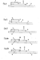
- FIG. 1 The structure of such a diagnostic agent according to the invention is shown in FIG. 1.
- the reaction layer 1 of the rapid diagnostic is glued onto a rigid base 2.
- a thin, liquid-permeable, dimensionally stable separating layer 4 is applied just above the reaction layer, which consists of a network of woven or matted plastic threads and which is glued to the base film in an easily detachable manner on both sides of the reaction film in such a way that an easy-to-grasp handle 4a remains free on the longer part of the base.
- the glass fiber paper 3 is now applied above the reaction layer. This is fixed in position by a further network 5 which, like the separating layer 4, is glued above and below the reaction layer.
- the reaction layer 1 can consist of an impregnated absorbent carrier or swellable or porous plastic film.
- a thicker plastic film, a solid cardboard, a glass plate or another stable carrier material is preferably used as the base 2.
- the plasma After applying a drop of blood 8 to the upper side of the rapid diagnostic, the plasma is separated from the erythrocytes and leucocytes in the glass fiber paper.
- the plasma separated in this way reaches the reaction zone 1 of the diagnostic agent via the separation layer 4.
- the separating layer After an appropriate time in which the plasma has entered the reaction zone, the separating layer is gripped at its free end and separated with the glass fiber paper and the network 5. The reaction layer in which the detection reaction now takes place can then be evaluated visually or remission photometrically.
- FIG. 2 A further possible structure of the rapid diagnostic according to the invention is illustrated in FIG. 2, one or more for in addition to the structure described above
- Liquids of all types permeable layers 6 are applied in such a way that they come to lie either above (FIG. 2a) or below (FIG. 2b) the glass fiber papers.
- These additional layers may be impregnated with reagents that are either readily soluble and get along with the plasma in the reaction zone or else are less soluble and have one or more precursors of Kachweisretress run already out of the final reaction zone. 1
- FIG. 3 another structure (Fig. 3a side view, Fi g. 3 b supervision) of the invention Schnelldiagnosticums described in which the glass fiber paper 3 is adhered directly to the backing 2.
- the reaction layer 1 is applied to part of the glass fiber paper.
- the blood 8 is applied to the remaining part of the glass fiber paper.
- the plasma separating from the erythrocytes in the glass fiber paper diffuses in the glass fiber paper to and into the reaction layer.
- the reaction colors that develop during the reaction can be observed and evaluated from the top of the rapid diagnostic.
- the reaction layer can be applied directly to the glass fiber paper by printing or coating. However, it can also be glued to the glass fiber paper in the form of a completely or partially impregnated absorbent carrier.
- the diagnostic agent according to the invention can be constructed in such a way that an absorbent material 9 such as cellulose paper or a plastic fleece and first the glass fiber paper 3 and the reaction layer are glued to the base 2 .
- This can suck capable material 9 occupy the same area as the reaction layer (FIG. 5) or a larger area, so that the material 9 leaves one area free (FIG. 4).
- the blood is dripped onto the remaining surface of the absorbent material (FIG. 4) or directly next to the absorbent material (FIG. 5) and is quickly absorbed by it and sucked under the glass fiber paper. Subsequently, blood is sucked up through the glass fiber paper by the absorbency of the glass fiber paper, the erythrocytes being separated and plasma reaching the reaction layer 1.
- the reaction is observed from the top of the rapid diagnostic as in FIG. 3.
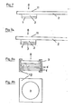
- Fig. 6 shows a further structure of a rapid diagnostic suitable for the direct use of whole blood.
- This is constructed in such a way that an absorbent layer 9, which consists, for example, of a cellulose paper or a cellulose-containing synthetic fiber fleece and a glass fiber layer 3 are applied to the rigid base 2.
- the two layers should have close contact.
- the diagnostic agent according to the invention can be produced in the form described in FIG. 7.
- the glass fiber paper 3 is glued onto a base 2.
- the base has one or more holes 11 at the contact point.
- a reaction layer 1 is applied directly or by gluing to the glass fiber paper.
- the blood 8 is applied to the diagnostic agent in such a way that it can reach the glass fiber paper 3 through the hole (or the holes).
- the plasma separated in the glass fiber paper now hits the reaction layer 1 and leads to the reaction, which can be evaluated visually or remission photometrically on its surface.
- the reaction layer is protected by a transparent cover layer 7.
- the reaction layer 1 can consist of either, e.g. consist of a layer printed on the glass fiber mat, but it can also consist of a multilayer element, in which the layers can contain different reagents and / or can fulfill several functions, e.g. described in DE-OS 29 22 958.
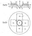
- FIG. 8a shows a side view and FIG. 8b shows a further structure of such a diagnostic agent according to the invention, in which the separating layer 3 consisting of glass fibers and one or more layers 6 necessary for the reaction are held together by a prefabricated mold 12 .
- the blood is dripped onto the side of the glass fiber filter.
- the severed Plasma then reaches reaction layer 1, the indicator reaction on the side opposite the glass fiber filter being evaluated visually or by reflectance photometry.
- the various layers are partially drawn with a gap.
- the layers lie one on top of the other so that liquids can pass freely.
- the reaction layers 1 and 6 are divided transversely to indicate that they can also consist of several layers lying one above the other.
- 3a, 3b, 4 and 6 can be significantly improved if a hydrophobic barrier 15 is applied to the glass fiber 5 next to or in the reaction layer 1, which partially protrudes into the volume of the glass fiber 3.
- 3 c, 3 d, 6 a and 6 b show this barrier 15 and otherwise correspond to the structure according to FIGS. 3, 4 and 6.
- This barrier 15 not only prevents blood 8 from settling on the surface of the glass fiber first spreads and contaminates the indicator area, it also decisively improves the separating effect of the glass fiber. It is therefore possible to work with relatively small glass fiber papers 3, which means that much smaller amounts of blood are required.
- the barrier can be made in a conventional manner e.g. be applied from nozzles or with wheels.
- the hydrophobic material for the barrier can e.g. a hot melt adhesive or a conventional solvent adhesive or wax.
- FIG. 9 describes the structure of a form according to the invention which separates plasma from the erythrocytes of whole blood without centrifuging and makes it available for diagnostic purposes.
- a tube or a vessel 13 e.g. has the shape described, filled with the glass fibers 14 described above.
- the blood 8 is filled into the vessel at the top.
- the plasma is now separated from the erythrocytes of the blood by the glass fibers.
- the plasma collecting in the lower part of the vessel 13 can now, e.g. can be taken up or aspirated through an "end-to-end" capillary and fed directly to another diagnostic method.
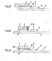
- FIG. 10 Another structure according to the invention is shown in FIG. 10, wherein the vessel 13 suitable for separating the erythrocytes can have the shape of a plunger syringe which is tightly filled with glass fibers 14 in the lower part.
- the blood 8 is introduced into the open-topped vessel. After separation of erythrocytes and plasma, with the plasma collecting in the lower part of the vessel, the plasma can first be pushed out of the syringe body by inserting and carefully pressing the plunger 17.
- the method according to the invention for obtaining plasma can also be carried out with a vessel 13, which is opened in two by a valve 16 which is permeable in one direction. Parts are separated and filled with the glass fibers described above. The blood 8 is filled into the vessel at the top. After separation from the erythrocytes, the plasma collects in the lower part of the vessel and can now be emptied by pressing the lower part of the vessel together. The valve 16 prevents that Plasma flows back into the upper part containing the blood cells.
- the method according to the invention can be carried out with an arrangement which is described by FIG. 1, wherein the reaction layer 1 glued to the base 2 consists of a defined absorbent material, so that a defined plasma volume reaches the layer 1 when blood is applied.
- the plasma i.e. the substance to be analyzed is eluted by a solvent.
- the elution of the plasma and the analysis can be carried out immediately, but also - depending on the substance to be analyzed - at a later point in time at another location. If the analysis is to be carried out later, it may be advantageous to dry the plasma first, for example with warm air or by freeze-drying. It is furthermore possible to provide one or more areas which contain reagents, separately from the area for the application of the sample, so that the entire reaction mixture is eluted simultaneously when eluting with a solvent.
- reaction layer 1 it is expedient to cover the reaction layer 1 with a covering layer 7 in order to avoid contamination of the measuring arrangement.
- the reaction layer is a film, for example according to DE-OS 29 1 0 134 or DE-PS 15 98 153, it is advisable to coat it directly on the cover layer 7 and then to mount both together.
- 3 e shows a possible embodiment.
- the cover layer 7 can also be applied to other embodiments, as shown in Fig. 7 a, which otherwise corresponds to the structure of FIG. 7.
- the reaction can only be started when the diagnostic agent has a sufficiently constant temperature.
- reagents can be accommodated which bring the substance to be detected into a certain state in a time-dependent reaction, i.e. run a pre-reaction.
- An example of this is the activation of creatine kinase with N-acetylcysteine.
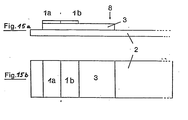
- FIG. 14 describes the use of a hydrophobic network 18 between the reaction layer and glass fiber 3 or suction layer 9. This hydrophobic net protects the arrangement from being accidentally touched lightly and only allows the liquid to come into contact with greater pressure. This contributes to an improved practicability.
- reaction layer 1 it is naturally possible for the reaction layer 1 to consist of 2 or more different districts. These can either detect the same substance in different concentration ranges or different substances if the recipes are selected accordingly. Furthermore, arrangements are also conceivable in which different reaction layers are simultaneously wetted by the plasma that originates from a dripping point. Various shapes are conceivable here, elongated, circular and the like.
- test areas 15 a to 17 b some possible arrangements are shown, the different test areas being distinguished from 1 a to 1 d and the other designations corresponding to the above figures.
- the blood separation can also be improved if a further glass fiber region 3 a is applied to the glass fiber 3 at the blood drop point.
- 3 a and 3 can consist of the same material, but a material of a different thickness or with a different fiber diameter can also be selected for 3 a.
- Cholesterol test strips are dissolved in 70 ml of water. Then one after another incorporated homogeneously. Finally 0.66 g of 3,3 ', 3,5'-tetramethylbenzidine dissolved in 1.6 ml of acetone is added. This approach is coated about 300 / u thick on a smooth plastic film and cut into 6 mm wide strips after drying at 60 ° C - 70 ° C. These strips are then combined with a 60 ⁇ thick network of nylon and a glass fiber paper cut into 6 mm wide strips (glass fiber filter No. 3362 from Schleicher & Schüll, paper thickness o, 47 mm, density o, 27 g / cm 3 , average fiber diameter approx. 2, ⁇ ) glued to a polyester film. Then it is cut into 6 mm wide strips.
- This reaction mass is placed in 6 mm wide strips with a screen printing machine (fabric: 190 / u) on a glass fiber paper (eg the glass fiber filter No. 85/90 from Macherey, Nagel & Co.) applied in the form described in Example 1.
- the printed glass fiber paper is dried at 60 ° C - 80 ° C and cut into 12 mm wide strips so that the printed reaction zone makes up half of the strip.
- This strip is glued to the end of a polyester film and cut into 6 mm wide strips across the glass fiber paper.
- the plasma diffuses under the reaction zone.
- the intensity of the reaction color corresponds to that which is obtained if, instead of the blood, spotted with the serum or plasma obtained from the same blood.
- a reagent mass consisting of is coated in a thickness of 0.2 mm on a hydrophobic polyester fleece (Reemay 2033 from Du Pont) and dried at 60 ° C. Then a 6 mm wide strip of this coating and a 12 mm wide strip of a glass fiber filter (e.g. the filter 3362 from Schleicher & Schüll) are glued side by side on a firm plastic strip so that the glass fiber filter abuts the coated fleece very closely.
- a glass fiber filter e.g. the filter 3362 from Schleicher & Schüll
- test strips are obtained in which, after about 50 ⁇ l of whole blood has been dripped onto the side of the glass fiber filter removed from the reagent fleece, only pure plasma passes into the reagent fleece after a short time and becomes a blue reaction color leads, the intensity of which increases with the concentration of cholesterol in the blood.
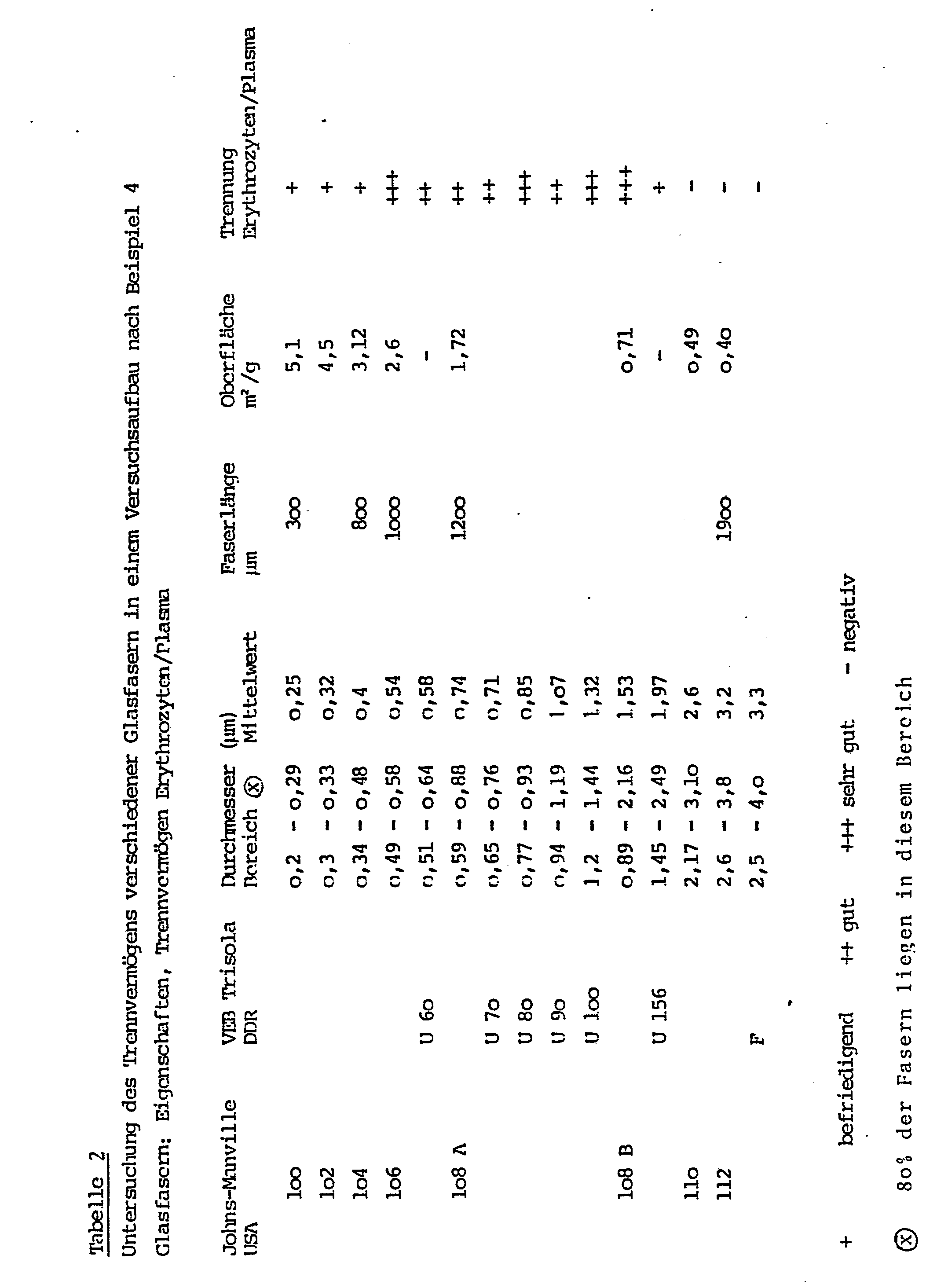
- a plastic container that tapers downwards conically (the plastic tip of a piston pipette, length 5 cm, thickness 0.5 cm) is filled 2/3 loosely with glass fibers according to the following Table 2, bulk densities of 0.1 - 0.4 g / cm 3 can be obtained.
- the serum diffuses into the tip of the vessel.
- an "end-to-end" capillary with 15 / ul content can be filled by guiding it to the pipette tip opening.
- the plasma obtained in this way can now be fed directly to any analytical method.
- devices according to FIG. 14 were produced which consist of a transparent polycarbonate carrier film 2 6 mm wide and 0.3 mm thick, a 9 ⁇ 6 mm absorbent layer 9 made of 0.09 mm thick Glass fiber paper, a hydrophobic nylon net 18 of o, o75 mm thick and a transparent cover sheet 7 are covered.
- a glass fiber paper 3 is attached to the carrier, which consists of glass fiber paper (Schleicher & Schüll, No. 3362, thickness o, 47 mm) of 6 mm width and the length given in the following table.
- One half of each of these devices is provided at the point of contact between layers 3, 9 and 18 with an approximately 2 mm wide, 0.1 mm thick paraffin wax barrier 15.
- the amounts of blood specified in the following table 3 are applied to the center of the glass fiber paper 3 and after 30 seconds the wetting of the absorbent layer 9 and, if appropriate, oversaturation (depth of penetration of the erythrocytes into the layer 9) are determined that the separation is improved by the hydrophobic barrier and complete saturation is achieved, so that such a test can be carried out with very small blood volumes, for example with capillary blood from the fingertip. The tests were carried out five times each and the results averaged.
Abstract
Die Erfindung betrifft ein Verfahren zum Abtrennen von Plasma oder Serum aus Vollblut, wobei man das Blut langsam durch eine Schicht aus Glasfasern mit einem mittleren Durchmesser von 0,2 - 5 µ und einer Dichte von 0,1 - 0,5 g cm³ sickern läßt und das ablaufende Plasma gewinnt, wobei das Volumen des abzutrennenden Plasmas oder Serum höchstens 50 %, vorzugsweise weniger als 30 % vom Saugvolumen der Glasfaserschicht beträgt, sowie Mitteln zur Durchführung des Verfahrens.The invention relates to a method for separating plasma or serum from whole blood, the blood slowly seeping through a layer of glass fibers with an average diameter of 0.2-5 .mu.m and a density of 0.1-0.5 g cm 3 and the running plasma wins, the volume of the plasma or serum to be separated being at most 50%, preferably less than 30% of the suction volume of the glass fiber layer, and means for carrying out the method.
Description
In der Klinischen Chemie ist die Abtrennung von Serum oder Plasma aus Blut von überragender - Bedeutung, da praktisch nur aus diesen beiden die Analyse von gelösten Blutbestandteilen störungsfrei durchgeführt werden kann.In clinical chemistry, the separation of serum or plasma from blood is of paramount importance, since it is practically only from these two that the analysis of dissolved blood components can be carried out without problems.
Die normale und gebräuchlichste Form der Abtrennung von .Serum oder Plasma von den Erythrozyten ist die Zentrifugation, Diese ist jedoch insbesondere bei der Verwendung kleiner Probenmengen problematisch, auch ist die Trennung von überstand und Blutkuchen nicht immer einfach, so daß hierfür eine ganze Reihe von Hilfsmitteln in der Literatur zu finden sind, z.B. DE-AS 25 59 242.The normal and most common form of separation of .serum or plasma from the erythrocytes is centrifugation, but this is particularly problematic when using small amounts of sample, and the separation of supernatant and blood cake is not always easy, so that a whole range of aids are required for this can be found in the literature, e.g. DE-AS 25 59 242.
Von besonderer Problematik ist die Verwendung von Vollblut bei Schnelldiagnostica. Schnelldiagnostica sind reagentienhaltige saugfähige oder quellbare Träger, vorzugsweise aus Filterpapier, auf die eine geringe Menge, z.B. ein Tropfen der zu untersuchenden Flüssigkeit aufgebracht wird und bei denen aufgrund der überwiegend sehr kurzen Reaktion eine Farbänderung eintritt, die entweder visuell bewertet wird oder remisionsphotometrisch ausgemessen wird. Da trübe und gefärbte Lösungen wie Blut die Ablesung stören, hat es daher nicht an Versuchen gefehlt, Schnelldiagnotica für die direkte Verwendung von Vollblut zugänglich zu machen. Hierbei sind z.B. zu nennen das überziehen von Testpapieren mit semipermeablen Membranen (US-P 3 092 465) und die Verwendung von wasserquellbaren Filmen, in die nur die gelösten Bestandteile des Blutes, nicht aber die Erythrozyten eindringen können (DE-AS 15 98 153). Diese beiden Verfahren sind an sich brauchbar, allerdings nur bei Testen für niedermolekulare Bestandteile des Blutes, wie z.B. Glucose oder Harnstoff; höhermolekulare Bestandteile des Blutes, wie z.B. Lipide oder die an Serum-Protein gebundenen Substrate wie z.B. Bilirubin, können auf diese Weise nicht bestimmt werden, weil sie nicht in der Lage sind, in den Film einzudringen bzw. durch die semipermeable Membran hindurchzugelangen. Weiterhin sind Vorschläge bekannt geworden, diagnostische Mittel zum Abtrennen der Blutzellen mit Membranfiltern zu bedecken (DE-AS 22 22 951 und DE-OS 29 22 958). Der Nachteil dieser diagnostischen Mittel ist, daß durch Membranfilter das Blut nur sehr langsam und in geringer Menge durchdringen kann, weil sie leicht verstopfen und die Reaktion entsprechend lange dauert. Im Gegensatz zu den vorher genannten diagnostischen Mitteln, die bereits im Handel sind, sind 'Schnellteste" der zuletzt geschilderten Art deshalb noch nicht im Handel erschienen.The use of whole blood in rapid diagnostics is particularly problematic. Rapid diagnostics are reagent-containing absorbent or swellable carriers, preferably made of filter paper, to which a small amount, e.g. a drop of the liquid to be examined, is applied and which, due to the predominantly very short reaction, undergoes a color change, which is either assessed visually or measured by remission photometry. Since cloudy and colored solutions such as blood interfere with the reading, there has been no shortage of attempts to make rapid diagnostics accessible for the direct use of whole blood. The coating of test papers with semipermeable membranes (US Pat. No. 3,092,465) and the Ver Use of water-swellable films into which only the dissolved components of the blood, but not the erythrocytes, can penetrate (DE-AS 15 98 153). These two methods are useful per se, but only in tests for low-molecular components of the blood, such as glucose or urea; Higher molecular components of the blood, such as lipids or the substrates bound to serum protein such as bilirubin, cannot be determined in this way because they are unable to penetrate the film or to pass through the semipermeable membrane. Furthermore, proposals have become known for covering diagnostic agents for separating the blood cells with membrane filters (DE-AS 22 22 951 and DE-OS 29 22 958). The disadvantage of these diagnostic agents is that membrane filters can only penetrate the blood very slowly and in small amounts because they clog easily and the reaction takes a correspondingly long time. In contrast to the previously mentioned diagnostic agents, which are already on the market, 'rapid tests' of the type described last have therefore not yet appeared on the market.
Aus den DE-OS 29 08 721 und 29 o8 722 ist weiterhin bekannt, daß man Lymphozyten beziehungsweise Leukozyten aus Blut abtrennen kann, wenn man das Blut über eine Schicht aus Kunstfasern mit mittleren Faserdurchmessern von 5 - 20µ beziehungsweise 3 - 10µ filtriert. Da die Erythrozyten aber überwiegend mit dem Plasma durch den Filter laufen, sind diese Filter nicht geeignet zur Gewinnung von Plasma. Rein spekulativ werden darüber hinaus Kohlenstoffasern, Glasfasern und Metallfasern genannt.From DE-OS 29 0 8 721 and 29 o8 722 it is further known that lymphocytes or leukocytes can be separated from blood if the blood is filtered through a layer of synthetic fibers with average fiber diameters of 5-20µ and 3-10µ. However, since the erythrocytes predominantly run through the filter with the plasma, these filters are not suitable for obtaining plasma. Carbon fibers, glass fibers and metal fibers are also mentioned purely speculatively.
Aufgabe der Erfindung war es daher, ein einfaches Mittel zum Abtrennen von Plasma oder Serum aus Vollblut zu finden, das ohne Zentrifugieren rasch und sicher kleine Mengen Blut trennt und insbesondere als Probenvorbereitung für diagnostische Zwecke geeignet ist.The object of the invention was therefore to find a simple means for separating plasma or serum from whole blood which quickly and safely separates small amounts of blood without centrifugation and is particularly suitable as sample preparation for diagnostic purposes.
Es wurde nun gefunden, daß die Abtrennung von Plasma bzw. Serum aus Vollblut schnell und einfach und in genügender Menge erfolgt, wenn man das Blut durch eine Schüttung aus Glasfasern allein oder in Mischung mit anderen Fasern strömen läßt. Diese Tatsache muß umsomehr als überraschend angesehen werden, als in der oben erwähnten DE-AS 22 22 951 die Verwendung von Glasfasermatten zur Abtrennung von weißen Blutzellen schon beschrieben ist, jedoch für die Abtrennung der Erythrozyten die zusätzliche Verwendung von Membranfiltern als unbedingt notwendig gefordert wird.It has now been found that the plasma or serum can be separated from whole blood quickly and easily and in sufficient quantity if the blood is allowed to flow through a bed of glass fibers alone or in a mixture with other fibers. This fact must be regarded as all the more surprising since the use of glass fiber mats for the separation of white blood cells has already been described in the above-mentioned DE-AS 22 22 951, but the additional use of membrane filters is absolutely necessary for the separation of the erythrocytes.
Die Erfindung ist in den Ansprüchen näher gekennzeichnet.The invention is characterized in more detail in the claims.
Die Glasfasern können lose gestapelt, sowie in Form von Papieren, Vliesen oder Filzen, aber auch gehalten durch eine äußere Form in jeder gewünschten Gestalt Verwendung finden.The glass fibers can be stacked loosely, in the form of papers, nonwovens or felts, but also held in any desired shape by an external shape.
Die so gestalteten Glasfasern können als Abdeckung für eines der oben beschriebenen Schnelldiagnostica dazu dienen, daß dieses diagnostische Mittel, für dessen Verwendung bisher die vorherige Gewinnung von Serum oder Plasma notwendig war, jetzt für die direkte Verwendung von Vollblut geeignet ist.The glass fibers designed in this way can serve as a cover for one of the rapid diagnostics described above so that this diagnostic agent, for the use of which previously the serum or plasma had previously been obtained, is now suitable for the direct use of whole blood.
Weiterhin können mit Glasfasern gefüllte Säulen, Filternutschen oder andere geeignete Gefäße auch dazu verwendet werden, durch einfaches Durchlaufen von Blut Serum oder Plasma ohne Zentrifugation zu gewinnen und diese in geeigneter Weise für diagnostische Mittel bereitzustellen, da das Serum bzw. Plasma schneller durch eine solche Schicht durchläuft, als die Erythrozyten und Leucozyten.Furthermore, columns filled with glass fibers, suction filters or other suitable vessels can also be used to obtain serum or plasma without centrifugation simply by running blood through them and to provide them in a suitable manner for diagnostic means, since the serum or plasma passes through such a layer more quickly passes through as the erythrocytes and leucocytes.
Die oben genannten Glasfasern können aus Fasern unterschiedlichen Durchmessers bestehen. Das Glasmaterial kann aus alkalihaltigem oder alkalifreiem Borosilikatglas, aber auch aus reinem Quarzglas bestehen. Fasermaterial aus anderen technischen Gläsern, z.B. borfreien Alkaligläsern, Kristallglas, Bleiglas u.a. befinden sich in den notwendigen Abmessungen der Fasern nicht im Handel und konnten daher nicht untersucht werden. Es wird aber davon ausgegangen, daß auch sie geeignet sind. Der mittlere Durchmesser der Glasfasern kann zwischen o,2/u bis etwa 5/u, vorzugsweise aber zwischen 0,5µ und 2,5/u, insbesondere zwischen o,5 und 1,5/u, liegen. Die Faserdurchmesser können entsprechend der Herstellung stark streuen, sollten jedoch eine Obergrenze von ca. 10µ nur ausnahmeweise überschreiten. Ihre Länge ist nur durch die Art der Stapelung begrenzt, hat aber ansonsten keinen Einfluß. Je nach Art der Stapelung werden Dichten von o,1 - o,5 , üblicherweise o,2 - o,4 g/cm3 gefunden.The glass fibers mentioned above can consist of fibers of different diameters. The glass material can consist of alkali-containing or alkali-free borosilicate glass, but also of pure quartz glass. Fiber material from other technical glasses, such as boron-free alkali glasses, crystal glass, lead glass, etc. are not commercially available in the necessary dimensions of the fibers and therefore could not be examined. However, it is assumed that they are also suitable. The average diameter of the glass fibers can be between 0.2 / u to about 5 / u, but preferably between 0.5μ and 2.5 / u, in particular between 0.5 and 1.5 / u. The fiber diameters can vary widely according to the production, but should only exceed an upper limit of approx. 10µ in exceptional cases. Their length is only limited by the type of stacking, but otherwise has no influence. Depending on the type of stacking, densities of o, 1 - o, 5, usually o, 2 - o, 4 g / cm 3 are found.
Weiterhin können die Glasfasern untereinander, aber auch mit Fasern aus anderen Materialien, vermischt werden, wodurch der innere Zusammenhalt der Fasern verbessert werden kann. Geeignet sind z.B. synthetische Fasern wie Polyester, Polyamid u.a., aber auch Fasern aus Polyethylen, Polypropylen und anderen nachträglich durch Wärme verformbaren Kunststoffen. Die Zusätze können auch höhere (10 - 20µ Durchmesser aufweisen, so lange ihre Menge nicht so groß ist, daß sie die. Abtrennung durch die erfindungsgemäßen,feineren Glasfasern beeinflussen.Furthermore, the glass fibers can be mixed with one another, but also with fibers made of other materials, as a result of which the internal cohesion of the fibers can be improved. Suitable are, for example, synthetic fibers such as polyester, polyamide, etc., but also fibers made of polyethylene, polypropylene and other plastics which can subsequently be deformed by heat. The additives may also higher (0: 1 - 20μ diameter have as long their amount is not so large as to affect the separation by the present invention, finer glass fibers..
Weiterhin können die Glasfasern durch Zusatz von anorganischen Bindemitteln (z.B. Wasserglas) oder organischen Bindemittel (z.B. Polyvinylacetat, Polyvinylpropionat, .Polyacrylsäureester u.a.) verfestigt werden, durch die die Glasfasern an den Berührungsstellen verklebt werden.Furthermore, the glass fibers can be solidified by adding inorganic binders (e.g. water glass) or organic binders (e.g. polyvinyl acetate, polyvinyl propionate, .polyacrylic acid ester, etc.), by means of which the glass fibers are bonded at the contact points.
Besonders bevorzugt ist die Kombination der erfindungsgemäßen Glasfaserschichten mit diagnostischen Mitteln, die ebenfalls Gegenstand der Erfindung ist.The combination of the glass fiber layers according to the invention with diagnostic agents, which is also the subject of the invention, is particularly preferred.
Die Glasfasern können in diesen diagnostischen Mitteln auch Reagenzien enthalten, die die Hämolyse der Erythrozyten verhindern, ferner Reagenzien, die die Gerinnung hemmen oder fördern sowie Reagenzien, die in der Indikatorschicht benötigt werden, mit den dortigen Reagenzien aber unverträglich sind. Diese letzteren Reagenzien können natürlich auch in allen Schichten untergebracht werden, die zwischen Glasfaser und Indikatorschicht liegen.In these diagnostic agents, the glass fibers can also contain reagents which prevent the hemolysis of the erythrocytes, further reagents which inhibit or promote coagulation and reagents which are required in the indicator layer but are incompatible with the reagents there. These latter reagents can of course also be accommodated in all layers that lie between the glass fiber and the indicator layer.
Den Aufbau eines solchen erfindungsgemäßen diagnostischen Mittels erläutert Fig. 1. Auf einer steifen Unterlage 2 ist die Reaktionsschicht 1 des Schnelldiagnosticums aufgeklebt. Dicht über der Reaktionsschicht ist eine dünne, für Flüssigkeiten durchlässige formstabile Trennschicht 4 aufgebracht, die aus einem Netzwerk aus gewebten oder verfilzten Kunststoff-Fäden besteht und die auf beiden Seiten der Reaktionsschicht'in leicht lösbarer Weise auf die Grundfolie in der Art geklebt ist, daß ein leicht zu fassender Griff 4a am längeren Teil der Unterlage freibleibt. Oberhalb der Reaktionsschicht ist nun das Glasfaserpapier 3 aufgebracht. Dieses wird durch ein weiteres Netzwerk 5 in seiner Lage fixiert, das wie die Trennschicht 4 oberhalb und unterhalb der Reaktionsschicht angeklebt ist.The structure of such a diagnostic agent according to the invention is shown in FIG. 1. The
Die Reaktionsschicht 1 kann aus einem imprägnierten saugfähigen Träger oder quellbarem oder porösem Kunststofffilm bestehen. Als Unterlage 2 dient vorzugsweise eine dickere Kunststoffolie, ein fester Karton, eine Glasplatte oder ein anderes stabiles Trägermaterial.The
Nach Aufbringen eines Bluttropfens 8 auf die obere Seite des Schnelldiagnosticms wird im Glasfaserpapier das Plasma von den Erythrozyten und Leucozyten abgetrennt. Das auf diese Weise abgetrennte Plasma gelangt über die Trennschicht 4 in die Reaktionszone 1 des diagnostischen Mittels. Nach einer angemessenen Zeit, in der das Plasma in die Reaktionzone eingedrungen ist, wird die Trennschicht an ihrem freien Ende ergriffen und mit dem Glasfaserpapier und dem Netzwerk 5 abgetrennt. Anschließend kann die Reaktionsschicht, in der nun die Nachweisreaktion stattfindet, visuell oder remissionsphotcmetrisch ausgewertet werden.After applying a drop of
Einen weiteren möglichen Aufbau des erfindungsgemäßen Schnelldiagnosticums verdeutlicht Fig. 2, wobei zusätzlich zu dem oben beschriebenen Aufbau eine oder mehrere für Flüssigkeiten aller Art durchlässige Schichten 6 in der Art.aufgebracht sind, daß sie entweder oberhalb (Fig. 2a) oder unterhalb (Fig. 2b) der Glasfaserpapiere zu liegen kommen. Diese zusätzlichen Schichten können mit Reagenzien imprägniert sein, die entweder leicht löslich sind und zusammen mit dem Plasma in die Reaktionszone gelangen oder aber weniger löslich sind und eine oder mehrere Vorstufen der Kachweisreaktion bereits außerhalb der endgültigen Re- aktionszone 1 ablaufen lassen.A further possible structure of the rapid diagnostic according to the invention is illustrated in FIG. 2, one or more for in addition to the structure described above Liquids of all types
In Fig. 3 wird ein anderer Aufbau (Fig. 3a Seitenansicht, Fig. 3b Aufsicht) des erfindungsgemäßen Schnelldiagnosticums beschrieben, bei dem das Glasfaserpapier 3 direkt auf die Unterlage 2 aufgeklebt ist. Auf einen Teil des Glasfaserpapieres ist die Reaktionsschicht 1 aufgebracht. Auf den freibleibenden Teil des Glasfaserpapieres wird das Blut 8 aufgetragen. Das sich im Glasfaserpapier von den Erythrozyten abtrennende Plasma diffundiert im Glasfaserpapier zu der Reaktionsschicht und in diese hinein. Die bei der Reaktion entstehenden Reaktionsfarben können von der Oberseite des Schnelldiagnosticums beobachtet und ausgewertet werden. Die Reaktionsschicht kann direkt durch Bedrucken oder Beschichten auf das Glasfaserpapier aufgebracht werden. Sie kann aber auch in Form eines ganz- oder teilimprägnierten saugfähigen Trägers auf das Glasfaserpapier aufgeklebt werden.In Fig. 3, another structure (Fig. 3a side view, Fi g. 3 b supervision) of the invention Schnelldiagnosticums described in which the
Weiterhin kann, wie in Fig. 4 und Fig. 5 beschrieben, das erfindungsgemäße diagnostische Mittel so aufgebaut sein, daß auf der Unterlage 2 zuerst ein saugfähiges Material 9 wie z.B. Cellulosepapier oder ein Kunststoffvlies und oberhalb dieses Materials das Glasfaserpapier 3 und die Reaktionsschichtl aufgeklebt sind. Dabei kann das saugfähige Material 9 die gleiche Fläche wie die Reaktionsschicht einnehmen (Fig. 5) oder aber eine größere Fläche, so daß das Material 9 eine Fläche freiläßt (Fig. 4). Das Blut wird auf die freibleibende Fläche des saugfähigen Materials (Fig. 4) oder direkt neben das saugfähige Material (Fig. 5) aufgetropft und von diesem schnell aufgenommen und unter das Glasfaserpapier gesaugt. Anschließend wird durch die Saugfähigkeit des Glasfaserpapieres Blut durch das Glasfaserpapier nach oben gesaugt, wobei die Abtrennung der Erythrozyten erfolgt und Plasma in die Reaktionsschicht 1, gelangt. Die Reaktion wird wie in Fig. 3 von der Oberseite des Schnelldiagnosticums beobachtet.Furthermore, as described in FIGS. 4 and 5, the diagnostic agent according to the invention can be constructed in such a way that an
Fig. 6 zeigt einen weiteren Aufbau eines für die direkte Verwendung von Vollblut geeigneten Schnelldiagnosticums. Dieses ist so aufgebaut, daß auf der steifen Unterlage 2 nebeneinander eine saugfähige Schicht 9, die z.B. aus einem Cellulosepapier oder aus einem cellulosehaltigen Kunstfaservlies besteht und eine Glasfaserschicht 3 aufgebracht sind. Die beiden Schichten sollen einen engen Kontakt aufweisen. Auf der Oberfläche der saugfähigen Schicht 9 befinden sich die für das Schnelldiagnosticum notwendigen Nachweisreagenzien, die z.B. durch Beschichten mit einem offenen Film gemäß DE-OS 29 10 134 aufgebracht sein können. Beim Auftragen des Bluttrop_ens auf die von der-Reaktionszone entferntere Seite der Glasfaserschicht findet die Trennung Plasma-Erythrozyten so statt, daß zuerst das Plasma mit seiner Front an der Trennstelle zu der saugfähigen Schicht 9 anlangt und sofort von dieser aufgesaugt wird. Durch Kapillarkräfte gelangt dann das Plasma in die Reaktionsschicht 1,WO sich die Nachweisreaktion z.B. durch eine von oben sichtbare Farbveränderung bemerkbar macht. Weiterhin kann das erfindungsgemäße diagnotische Mittel in der in Fig. 7 beschriebenen Form hergestellt werden. Dabei wird das Glasfaserpapier 3 auf eineUnterlage 2 aufgeklebt. Die Unterlage hat an der Berührungsstelle ein oder mehrere Löcher 11. Auf der anderen Seite ist eine Reaktionsschicht 1 direkt oder durch Kleben auf das Glasfaserpapier aufgebracht. Das Blut 8 wird so auf das diagnostische Mittel aufgebracht, daß es durch das Loch (oder die Löcher) auf das Glasfaserpapier 3 gelangen kann. Das im Glasfaserpapier abgetrennte Plasma trifft nun auf die Reaktionsschicht 1 und führt zu der Reaktion, die visuell oder remissionsphotometrisch an deren Oberfläche ausgewertet werden kann. Die Reaktionsschicht ist dabei durch eine durchsichtige Abdeckschicht 7 geschützt.Fig. 6 shows a further structure of a rapid diagnostic suitable for the direct use of whole blood. This is constructed in such a way that an
Die Reaktionsschicht 1 kann sowohl aus einer, z.B. auf die Glasfasermatte aufgedruckten Schicht bestehen, sie kann aber auch aus einem mehrschichtigen Element bestehen, bei dem die Schichten verschiedene Reagenzien enthalten können und/oder mehrere Funktionen erfüllen können, wie z.B. in der DE-OS 29 22 958 beschrieben.The
Fig. 8a zeigt in der Seitenansicht und Fig. 8b zeigt in der Aufsicht einen weiteren Aufbau eines solchen erfindungsgemäßen diagnostischen Mittels, bei dem die aus Glasfasern bestehende Trennschicht 3 sowie eine oder mehrere für die Reaktion notwendigen Schichten 6 durch eine vorgefertigte Form12 zusammengehalten werden. Das Blut wird hierbei auf die Seite des Glasfaserfilters aufgetropft. Das abgetrennte Plasma gelangt anschließend in die Reaktionsschicht 1 wobei die Indikatorreaktion auf der dem Glasfaserfilter gegenüberliegenden Seite visuell oder remissionsphotometrisch ausgewertet wird.8a shows a side view and FIG. 8b shows a further structure of such a diagnostic agent according to the invention, in which the
Aus zeichentechnischen Gründen sind in einigen Figuren die verschiedenen Schichten teilweise mit einem Zwischenraum gezeichnet. In der praktischen Ausführung liegen die Schichten aufeinander, so daß Flüssigkeiten ungehindert übertreten können. Weiterhin sind die Reaktionsschichten 1 und 6 querunterteilt, um anzudeuten, daß sie auch aus mehreren übereinanderliegenden Schichten bestehen können.For reasons of drawing technology, in some figures the various layers are partially drawn with a gap. In practice, the layers lie one on top of the other so that liquids can pass freely. Furthermore, the reaction layers 1 and 6 are divided transversely to indicate that they can also consist of several layers lying one above the other.
Die Blutabtrennung mit Mitteln gemäß Fig. 3a, 3b, 4 und 6 läßt sich wesentlich verbessern, wenn man auf die Glasfaser 5 neben oder in der Reaktionsschicht 1 eine hydrophobe Barriere 15 aufbringt, die teilweise in das Volumen der Glasfaser 3 hineinragt. Die Fig. 3 c, 3 d, 6 a und 6 b zeigen diese Barriere 15 und entsprechen im übrigen dem Aufbau gemäß Fig. 3, 4 und 6. Diese Barriere 15 verhindert nicht nur, daß sich Blut 8 an der Oberfläche der Glasfaser zuerst ausbreitet und den Indikatorbezirk verunreinigt, sie verbessert auch entscheidend die Trennwirkung der Glasfaser. Es kann deshalb mit relativ kleinen Glasfaserpapieren 3 gearbeitet werden, was zur Folge hat, daß wesentlich kleinere Blutmengen benötigt werden. Die Barriere kann auf herkömmliche Weise, z.B. aus Düsen oder mit Rädern aufgebracht werden. Das hydrophobe Material für die Barriere kann z.B. ein Schmelzkleber oder ein herkömmlicher Lösungsmittelkleber oder Wachs sein.3a, 3b, 4 and 6 can be significantly improved if a
Desweiteren beschreibt Fig. 9 den Aufbau einer erfindungsgemäßen Form, die Plasma von den Erythrozyten des Vollblutes ohne Zentrifugieren abtrennt und für diagnostische Zwecke bereitstellt. Dazu wird ein Rohr oder ein Gefäß 13, das z.B. die beschriebene Form hat, mit den oben beschriebenen Glasfasern 14 gefüllt. Das Blut 8 wird oben in das Gefäß eingefüllt. Auf dem Weg nach unten wird nun durch die Glasfasern das Plasma von den Erythrozyten des Blutes abgetrennt. Das sich im unteren Teil des Gefäßes 13 sammelnde Plasma kann nun.z.B. durch eine "end-to-end"-Kapillare aufgenommen oder abgesaugt werden und direkt einem anderen diagnostischen Verfahren zugeführt werden.Furthermore, FIG. 9 describes the structure of a form according to the invention which separates plasma from the erythrocytes of whole blood without centrifuging and makes it available for diagnostic purposes. For this purpose, a tube or a
Einen anderen erfindungsgemäßen Aufbau beschreibt die Fig. 10, wobei das zur Abtrennung der Erythrozyten geeignete Gefäß 13 die Form einer Kolbenspritze aufweisen kann, die im unteren Teil mit Glasfasern 14 dicht gefüllt ist. Das Blut8wird in das oben offene Gefäß eingebracht. Nach erfolgter Trennung von Erythrozyten und Plasma, wobei das Plasma sich im unteren Gefäßteil sammelt, kann durch Einführen und vorsichtiges Drücken des Kolbens 17 zuerst das Plasma aus dem Spritzenkörperherausgedrückt werden.Another structure according to the invention is shown in FIG. 10, wherein the
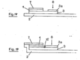
Das erfindungsgemäße Verfahren zur Plasma-Gewinnung kann, wie in Fig. 11 beschrieben, auch mit einem Gefäß 13 durchgeführt werden, das durch ein in einer Richtung durchlässiges Ventil 16 in zwei. Teile getrennt ist und mit den oben beschriebenen Glasfasern gefüllt ist. Das Blut 8 wird oben in das Gefäß eingefüllt. Das Plasma sammelt sich nach der Abtrennung von den Erythrozyten im unteren Teil des Gefäßes und kann nun durch Zusammenpressen des unteren Gefäßteiles entleert werden. Dabei verhindert das Ventil 16, daß das Plasma in den oberen, die Blutzellen enthaltenden Teil zurückströmt.As described in FIG. 11, the method according to the invention for obtaining plasma can also be carried out with a
Weiterhin kann das erfindungsgemäße Verfahren mit einer Anordnung durchgeführt werden, die durch Fig. 1 beschrieben wird, wobei die auf die Unterlage 2 geklebte Reaktionsschicht 1 aus einem definiert saugenden Material besteht, so daß beim Auftragen von Blut ein definiertes Plasmavolumen in die Schicht 1 gelangt. Nach dem Abtrennen der Schichten 3, 4 und 5 kann das Plasma, d.h. die zu analysierende Substanz durch ein Lösungsmittel eluiert werden. Die Elution des Plasmas und die Analyse kann sofort, aber auch - je nach zu analysierender Substanz - zu einem späteren Zeitpunkt an anderem Ort durchgeführt werden. Falls die Analyse erst später durchgeführt werden soll, kann es vorteilhaft sein, das Plasma zunächst, beispielsweise mit warmer Luft oder durch Gefrertrocknen, einzutrocknen. Es ist weiterhin möglich, getrennt von dem Bezirk für das Aufbringen der Probe, einen oder mehrere Bereiche vorzusehen, die Reagenzien enthalten, so daß beim Eluieren mit einem Lösungsmittel das ganze Reaktionsgemisch gleichzeitig eluiert wird.Furthermore, the method according to the invention can be carried out with an arrangement which is described by FIG. 1, wherein the
Wenn die Reaktionsfarben nicht nur visuell ausgewertet werden sollen, sondern in Remissionsphotometern gemessen werden sollen, ist es zweckmäßig, die Reaktionsschicht 1 mit einer Abdeckschict 7 zu bedecken, um eine Verschmutzung der Meßanordnung zu vermeiden. Ist die Reaktionsschichtl ein Film etwa gemäß DE-OS 29 10 134 oder DE-PS 15 98 153, so ist es zweckmäßig diese direkt auf die Abdeckschicht 7 zu beschichten und dann beide gemeinsam zu montieren. Eine mögliche Ausführungsform zeigt Fig. 3 e. Naturgemäß ist die Abdeckschicht 7 auch anwendbar auf andere Ausführungsformen, wie es in Fig. 7 a gezeigt ist, die im übrigen dem Aufbau gemäß Fig. 7 entspricht.If the reaction colors are not only to be evaluated visually, but are to be measured in reflectance photometers, it is expedient to cover the
Es hatte sich weiterhin als vorteilhaft erwiesen, Anordnungen zu wählen, bei dem die Reaktionsschicht 1 zunächst nicht mit der Glasfaser 3 bzw. der saugfähigen Schicht 9 in flüssigkeitsleitender Berührung ist, sondern daß diese Berührung erst dann herbeigeführt wird, wenn sich die genannten Schichten vollständig mit Plasma bzw. Serum gefüllt haben. Die Vorteile dieser Anordnungen sind, daß das Plasma bzw. Serum mit der Reaktionsschicht 1 zu einem vorher bestimmbaren exakten Zeitpunkt in Berührung gebracht werden können. Ferner erfolgt diese Berührung über die ganze Fläche, so daß Chromatographieeffekte, wie sie bei den vorstehenden Anordnungen gegebenenfalls auftreten können, ausgeschlossen sind. Die Tatsache, daß zwischen Aufgeben des Blutes 8 und Beginn der Reaktion in der Reaktionsschichtl eine vorher bestimmbare Zeit gelegt werden kann, ist von großer Bedeutung bei Reaktionen die unter besonders kontrollierten Bedingungen ablaufen müssen. So kann bei der Bestimmung von Enzymen, die bei besonders konstanter Temperatur ablaufen muß, die Reaktion erst gestartet werden, wenn das diagnostische Mittel hinreichend konstant temperiert ist. Ebenso können in den Zonen von 3 und 9, in denen sich das Plasma sammelt, Reagenzien untergebracht werden, die den nachzuweisenden Stoff in zeitabhängiger Reaktion in einen bestimmten Zustand bringen, d.h. eine Vorreaktion ablaufen lassen. Ein Beispiel hierfür ist die Aktivierung der Creatin-Kinase mit N-Acetylcystein.It had also proven to be advantageous to choose arrangements in which the
Fig. 12, .13 und 14 beschreiben verschiedene mögliche Anordnungen, wobei in Fig. 13 die hydrophobe Barriere 15 gleichzeitig als Befestigung der Schichten 1 und 7 dient. Die Bezeichnungen und Zusammensetzungen der übrigen Schichten entsprechen den Fig. 3 bis 6.12, .13 and 14 describe various possible arrangements, with the
In Fig. 14 ist die Verwendung eines hydrophoben Netzes 18 zwischen Reaktionsschicht und Glasfaser 3 bzw. Saugschicht 9 beschrieben. Dieses hydrophobe Netz schützt die Anordnung vor unbeabsichtigtem leichtem Berühren und läßt den Flüssigkeitskontakt erst bei stärkerem Anpressen eintreten. Dies trägt zu einer verbesserten Praktikabilität bei.FIG. 14 describes the use of a
Naturgemäß ist es möglich, daß die Reaktionsschicht 1 aus 2 oder mehreren voneinander verschiedenen Bezirken bestehen kann. Diese können entweder die gleiche Substanz in verschiedenen Konzentrationsbereichen oder aber verschiedene Substanzen nachweisen, wenn die Rezepturen entsprechend ausgewählt sind. Ferner sind auch Anordnungen denkbar, bei denen gleichzeitig verschiedene Reaktionsschichten von dem Plasma, das aus einer Auftropfstelle herrührt, benetzt werden. Es sind hier die verschiedensten Formen denkbar, längliche, kreisförmige und dergleichen.It is naturally possible for the
In Fig. 15 a bis 17 b sind einige mögliche Anordnungen dargestellt, wobei die verschiedenen Testbezirke mit 1 a bis 1 d unterschieden wurden und die übrigen Bezeichnungen den vorstehenden Fig. entsprechen.15 a to 17 b some possible arrangements are shown, the different test areas being distinguished from 1 a to 1 d and the other designations corresponding to the above figures.
Die Blutabtrennung kann gleichfalls verbessert werden, wenn auf der Glasfaser 3 an der Blutauftropfstelle noch ein weiterer Glasfaserbezirk 3 a aufgebracht wird. Hierbei kann 3 a und 3 aus dem gleichen Material bestehen, es kann aber auch für 3 a ein Material anderer Dicke, bzw. mit anderem Faserdurchmesser gewählt werden.The blood separation can also be improved if a further
Fig. 18 und 19 zeigen mögliche Anordnungen, die im übrigen den Fig. 3 und 12 entsprechen.18 and 19 show possible arrangements which otherwise correspond to FIGS. 3 and 12.
In den folgenden Beispielen soll die Erfindung näher erläutert werden:The invention will be explained in more detail in the following examples:
Cholesterin-Teststreifen


Betüpfelt man die Oberseite des Teststreifens mit 40 µl Blut und entfernt nach 1 Minute das Glasfaserpapier mit dem restlichen Blut zusammen mit dem Netzwerk durch Abreißen, dann bildet sich innerhalb von 3 Minuten auf dem Testbezirk eine Reaktionsfarbe, die derjenigen entspricht, die man erhält, wenn anstelle des Blutes mit dem abzentrifugierten Plasma des gleichen Blutes getüpfelt wird.Dab the top of the test strip with 40 µl of blood and after 1 minute remove the glass fiber paper with the rest of the blood together with the network by tearing off, then within 3 minutes a reaction color forms on the test area which corresponds to that which is obtained when instead of the blood is spotted with the centrifuged plasma of the same blood.


In gleicher Weise können auch die in der folgenden Tabelle 1 aufgeführten Papiere verwendet werden.

Eine Reagenzienmasse, bestehend aus

Ein sich nach unten konisch verjüngendes Kunststoffgefäß (die Kunststoffspitze einer Kolbenhubpipette, Länge 5 cm, Dicke o,5 cm) wird zu 2/3 mit Glasfasern gemäß der folgenden Tabelle 2 locker gefüllt, wobei Schüttdichten von o,1 - o,4 g/cm3 erhalten werden. Nachdem der obere freie Teil mit Blut gefüllt wurde, diffundiert das Serum in die Gefäßspitze. Von dort kann eine "end-to-end"-Kapillare mit 15/ul Inhalt durch Heranführen an die Pipettenspitzenöffnung gefüllt werden. Das auf diese Weise gewonnene Plasma kann nun direkt jedem beliebigen analytischen Verfahren zugeführt werden.
Zur Verdeutlichung der Effekte einer hydrophoben Barriere 15 , wurden Vorrichtungen gemäß Figur 14 hergestellt, die aus einer durchsichtigen Polycarbonat-Trägerfolie 2 von 6 mm Breite und o,3 mm Dicke, einer 9 x 6 mm großen saugfähigen Schicht 9 aus o,o9 mm dickem Glasfaserpapier, einem hydrophoben Nylonnetz 18 von o,o75 mm Dicke und einer transparenten Abdeckfolie 7 abgedeckt sind. In saugfähigem Kontakt mit der Schicht 9 ist ein Glasfaserpapier 3 auf dem Träger befestigt, das aus Glasfaserpapier (Schleicher & Schüll, Nr. 3362, Dicke o,47 mm) von 6 mm Breite und der in der folgenden Tabelle angegebenen Länge besteht. Jeweils eine Hälfte dieser Vorrichtungen wird an der Berührungsstelle zwischen den Schichten 3, 9 und 18 mit einer etwa 2 mm breiten o,1 mm dicken Barriere 15 aus Paraffinwachs versehen.In order to clarify the effects of a
Zur Ermittlung der Plasmagewinnung werden auf die Mitte des Glasfaserpapieres 3 die in der folgenden Tabelle 3 angegebenen Blutmengen aufgetragen und nach 3o Sekunden die Benetzung der saugfähigen Schicht 9 sowie gegebenenfalls eine Übersättigung (Eindringtiefe der Erythrozyten in die Schicht 9) bestimmt.Die Ergebnisse der Tabelle zeigen, daß durch die hydrophobe Barriere die Trennung verbessert und eine vollständige Sättigung erreicht wird, so daß man bereits mit sehr kleinen Blutvolumina, beispielsweise mit Kapillarblut aus der Fingerbeere, einen solchen Test durchführen kann. Die Versuche wurden jeweils fünffach durchgeführt und die Ergebnisse gemittelt.

- 1 Reaktionsschicht1 reaction layer
- 2 Unterlage2 pad
- 3 Glasfaserpapier/Glasfaserschicht/Trennschicht3 glass fiber paper / glass fiber layer / separation layer
- 3a Glasfaserbezirk3a fiber optic district
- 4 Trennschicht4 separation layer
- 4a Griff4a handle
- 5 Netzwerk5 network
- 6 durchlässige Schicht6 permeable layer
- 7 durchsichtige Abdeckschicht7 transparent cover layer
- 8 Bluttropfen/Blut8 drops of blood / blood
- 9 saugfähiges Material/Schicht9 absorbent material / layer
- 11 Löcher11 holes
- 12 vorgefertigte Form12 pre-made form
- 13 Gefäß13 vessel
- 14 Glasfasern14 glass fibers
- 15 hydrophobe Barriere15 hydrophobic barrier
- 16 Ventil16 valve
- 17 Kolben17 pistons
- 18 hydrophobes Netz18 hydrophobic mesh
Claims (13)
Priority Applications (1)
| Application Number | Priority Date | Filing Date | Title |
|---|---|---|---|
| AT81105956T ATE16218T1 (en) | 1980-08-05 | 1981-07-29 | PROCEDURE FOR SEPARATION OF PLASMA OR SERUM FROM WHOLE BLOOD. |
Applications Claiming Priority (2)
| Application Number | Priority Date | Filing Date | Title |
|---|---|---|---|
| DE3029579A DE3029579C2 (en) | 1980-08-05 | 1980-08-05 | Method and means for separating plasma or serum from whole blood |
| DE3029579 | 1980-08-05 |
Publications (2)
| Publication Number | Publication Date |
|---|---|
| EP0045476A1 true EP0045476A1 (en) | 1982-02-10 |
| EP0045476B1 EP0045476B1 (en) | 1985-10-23 |
Family
ID=6108896
Family Applications (1)
| Application Number | Title | Priority Date | Filing Date |
|---|---|---|---|
| EP81105956A Expired EP0045476B1 (en) | 1980-08-05 | 1981-07-29 | Method for separating plasma or serum from blood |
Country Status (18)
| Country | Link |
|---|---|
| US (1) | US4477575A (en) |
| EP (1) | EP0045476B1 (en) |
| JP (2) | JPH0664054B2 (en) |
| AT (1) | ATE16218T1 (en) |
| AU (1) | AU525394B2 (en) |
| CA (1) | CA1177374A (en) |
| CS (1) | CS235005B2 (en) |
| DD (1) | DD201388A5 (en) |
| DE (2) | DE3029579C2 (en) |
| DK (1) | DK155636C (en) |
| ES (1) | ES504542A0 (en) |
| FI (1) | FI71999C (en) |
| HU (1) | HU186398B (en) |
| IE (1) | IE51623B1 (en) |
| IL (1) | IL63492A (en) |
| PL (1) | PL141490B1 (en) |
| SU (1) | SU1424723A3 (en) |
| ZA (1) | ZA815337B (en) |
Cited By (41)
| Publication number | Priority date | Publication date | Assignee | Title |
|---|---|---|---|---|
| WO1983000229A1 (en) * | 1981-07-06 | 1983-01-20 | Per Stahl Skov | A method of detecting or determining histamine in histamine containing materials, particularly body fluids and an analytical means for use in such method |
| EP0133895A1 (en) * | 1983-07-02 | 1985-03-13 | Roche Diagnostics GmbH | Substrate for retaining erythrocytes |
| EP0155003A2 (en) * | 1984-03-15 | 1985-09-18 | ASAHI MEDICAL Co., Ltd. | Filtering unit for removing leukocytes |
| EP0160916A2 (en) * | 1984-04-27 | 1985-11-13 | Fuji Photo Film Co., Ltd. | Part of an analytical element for the analysis of a solid in a liquid sample |
| EP0183991A1 (en) * | 1984-11-10 | 1986-06-11 | MERCK PATENT GmbH | Method for the separation of whole blood |
| EP0194502A2 (en) * | 1985-03-09 | 1986-09-17 | MERCK PATENT GmbH | Means and method for the separation of plasma or serum from whole blood |
| EP0198628A1 (en) * | 1985-04-11 | 1986-10-22 | Smithkline Diagnostics, Inc. | Device and method for whole blood separation and analysis |
| EP0199205A1 (en) * | 1985-04-22 | 1986-10-29 | Miles Inc. | Sealed reagent matrix |
| EP0208952A1 (en) * | 1985-06-29 | 1987-01-21 | Roche Diagnostics GmbH | Test strip |
| EP0239002A1 (en) * | 1986-03-27 | 1987-09-30 | Roche Diagnostics GmbH | Test support and method for the determination of coagulation parameters |
| EP0245802A2 (en) * | 1986-05-16 | 1987-11-19 | Roche Diagnostics GmbH | Test device for determination of blood clotting parameters |
| EP0297390A2 (en) * | 1987-06-27 | 1989-01-04 | Roche Diagnostics GmbH | Process for the manufacture of a diagnostic-test support, and test support therefor |
| EP0305803A2 (en) * | 1987-08-31 | 1989-03-08 | BEHRINGWERKE Aktiengesellschaft | Apparatus and method for separating blood cells from erythrocyte containing body fluids and its use |
| EP0309883A2 (en) * | 1987-09-30 | 1989-04-05 | Roche Diagnostics GmbH | Test strip for the determination of an analyte in a body fluid |
| US4880548A (en) * | 1988-02-17 | 1989-11-14 | Pall Corporation | Device and method for separating leucocytes from platelet concentrate |
| US4923620A (en) * | 1987-10-20 | 1990-05-08 | Pall Corporation | Device for depletion of the leukocyte content of blood and blood components |
| US4925572A (en) * | 1987-10-20 | 1990-05-15 | Pall Corporation | Device and method for depletion of the leukocyte content of blood and blood components |
| WO1990010869A1 (en) * | 1989-03-08 | 1990-09-20 | Cholestech Corporation | Analyte assay device and apparatus |
| EP0415298A2 (en) * | 1989-09-01 | 1991-03-06 | Roche Diagnostics GmbH | Method for the determination of HDL-cholesterol using analytical element with integrated fractionation |
| EP0436897A2 (en) * | 1990-01-12 | 1991-07-17 | Miles Inc. | Device and method of separating and assaying whole blood |
| EP0526226A2 (en) * | 1991-08-02 | 1993-02-03 | Ortho Pharmaceutical Corporation | Device and method for conducting biological assays containing particulate screening system |
| WO1993003842A2 (en) * | 1991-08-26 | 1993-03-04 | Actimed Laboratories, Inc. | Method and device for metering of fluid samples |
| US5229012A (en) * | 1989-05-09 | 1993-07-20 | Pall Corporation | Method for depletion of the leucocyte content of blood and blood components |
| US5262067A (en) * | 1990-05-15 | 1993-11-16 | Boehringer Mannheim Gmbh | Device and its use for the separation of plasma from whole blood |
| EP0571941A1 (en) * | 1992-05-29 | 1993-12-01 | Roche Diagnostics GmbH | Non-woven fabric containing test carrier |
| US5344561A (en) * | 1989-05-09 | 1994-09-06 | Pall Corporation | Device for depletion of the leucocyte content of blood and blood components |
| EP0750196A2 (en) * | 1995-06-24 | 1996-12-27 | Roche Diagnostics GmbH | Multi-layer analytical element for the determination of an analyte in a fluid |
| EP0806666A2 (en) * | 1996-05-09 | 1997-11-12 | Syntron Bioresearch, Inc. | Method and apparatus for single step assays of whole blood |
| EP1114997A2 (en) * | 1999-12-28 | 2001-07-11 | ARKRAY, Inc. | Blood testing tool |
| US6506575B1 (en) | 1999-09-24 | 2003-01-14 | Roche Diagnostics Gmbh | Analytical element and method for the determination of an analyte in a liquid |
| US6592815B1 (en) | 1997-12-04 | 2003-07-15 | Roche Diagnostics Gmbh | Analytical test element with a narrowed capillary channel |
| EP1452857A1 (en) * | 2001-11-14 | 2004-09-01 | Matsushita Electric Industrial Co., Ltd. | Biosensor |
| EP1531331A2 (en) | 2003-10-31 | 2005-05-18 | Roche Diagnostics GmbH | Method for the determination of an analyte by means of an extraction layer |
| US6966977B2 (en) | 2000-07-31 | 2005-11-22 | Matsushita Electric Industrial Co., Ltd. | Biosensor |
| US7008799B1 (en) | 1997-12-04 | 2006-03-07 | Roche Diagnostics Gmbh | Analytical test element with a capillary channel |
| USRE39915E1 (en) | 1989-09-01 | 2007-11-06 | Roche Diagnostics Gmbh | Method for the determination of HDL cholesterol by means of a rapid diagnostic agent with an integrated fractionating step |
| US7795038B2 (en) | 2002-04-09 | 2010-09-14 | Cholestech Corporation | High-density lipoprotein assay device and method |
| US7824879B2 (en) | 2007-01-09 | 2010-11-02 | Cholestech Corporation | Device and method for measuring LDL-associated cholesterol |
| US8409815B2 (en) | 2002-11-16 | 2013-04-02 | Siemens Healthcare Diagnostics Products Gmbh | sCD40L and placental growth factor (PLGF) used as a biochemical marker combination in cardiovascular diseases |
| US8697006B2 (en) | 2005-05-20 | 2014-04-15 | Orion Diagnostica Oy | Application of a reagent to a matrix material |
| EP3564667A4 (en) * | 2016-12-28 | 2019-12-25 | Fujifilm Corporation | Blood test kit and blood analysis method |
Families Citing this family (239)
| Publication number | Priority date | Publication date | Assignee | Title |
|---|---|---|---|---|
| DE3130749C2 (en) * | 1981-08-04 | 1984-06-07 | Boehringer Mannheim Gmbh, 6800 Mannheim | Rapid diagnostic agent and method for its use, in particular for quantitative determinations |
| EP0160640A1 (en) * | 1982-12-22 | 1985-11-13 | University Of Queensland | Microassay of cell adherence |
| DE3247608A1 (en) * | 1982-12-23 | 1984-07-05 | Boehringer Mannheim Gmbh, 6800 Mannheim | TEST STRIP |
| DE3302383C2 (en) * | 1983-01-25 | 1985-08-29 | Michael J. 8000 München Lysaght | Method and device for obtaining blood plasma |
| USRE34405E (en) * | 1983-08-01 | 1993-10-12 | Abbott Laboratories | Determination of analytes in particle-containing medium |
| DE3425118A1 (en) * | 1984-07-07 | 1986-01-16 | Boehringer Mannheim Gmbh, 6800 Mannheim | NEW REDOX INDICATORS |
| US4623461A (en) * | 1985-05-31 | 1986-11-18 | Murex Corporation | Transverse flow diagnostic device |
| DE3523969A1 (en) * | 1985-07-04 | 1987-01-08 | Boehringer Mannheim Gmbh | Coagulation-neutral, hydrophilic glass fibers |
| TW203120B (en) * | 1985-10-04 | 1993-04-01 | Abbott Lab | |
| US4839296A (en) * | 1985-10-18 | 1989-06-13 | Chem-Elec, Inc. | Blood plasma test method |
| US4916056A (en) * | 1986-02-18 | 1990-04-10 | Abbott Laboratories | Solid-phase analytical device and method for using same |
| US5160701A (en) * | 1986-02-18 | 1992-11-03 | Abbott Laboratories | Solid-phase analytical device and method for using same |
| US5081017A (en) * | 1986-02-18 | 1992-01-14 | Texas Bioresource Corporation | Method and apparatus for detection and quantitation of bacteria |
| US4906439A (en) * | 1986-03-25 | 1990-03-06 | Pb Diagnostic Systems, Inc. | Biological diagnostic device and method of use |
| US4935346A (en) | 1986-08-13 | 1990-06-19 | Lifescan, Inc. | Minimum procedure system for the determination of analytes |
| DE3630999A1 (en) * | 1986-09-12 | 1988-03-17 | Boehringer Mannheim Gmbh | MULTI-LAYER TEST CARRIER |
| US5057438A (en) * | 1986-09-24 | 1991-10-15 | Agency Of Industrial Science And Technology | Electrophoretic antigen-antibody determination with laminate of multiple membranes |
| US4753776A (en) * | 1986-10-29 | 1988-06-28 | Biotrack, Inc. | Blood separation device comprising a filter and a capillary flow pathway exiting the filter |
| DE3638654A1 (en) * | 1986-11-12 | 1988-05-26 | Boehringer Mannheim Gmbh | TEST CARRIER FOR ANALYTICAL DETERMINATION OF A COMPONENT OF A BODY LIQUID |
| US4849340A (en) * | 1987-04-03 | 1989-07-18 | Cardiovascular Diagnostics, Inc. | Reaction system element and method for performing prothrombin time assay |
| US4959324A (en) * | 1989-03-16 | 1990-09-25 | Chemtrak, Inc. | Sample pad assay initiation device and method of making |
| US4987085A (en) * | 1987-06-22 | 1991-01-22 | Chemtrak Inc. | Blood filtering metering device |
| US4883764A (en) * | 1987-07-20 | 1989-11-28 | Kloepfer Mary A | Blood test strip |
| DE3725766A1 (en) * | 1987-08-04 | 1989-02-16 | Boehringer Mannheim Gmbh | TEST CARRIER FOR DETERMINING AN ANALYTE FROM BLOOD AND METHOD FOR THE PRODUCTION THEREOF |
| NL8800796A (en) * | 1988-03-29 | 1989-10-16 | X Flow Bv | METHOD FOR THE CHEMICAL ANALYSIS OF BODY FLUID COMPONENTS, AND A TESTING DEVICE AND TEST PACKAGE FOR SUCH ANALYSIS. |
| US5423989A (en) * | 1988-05-19 | 1995-06-13 | Chemtrack, Inc. | Plasma forming device |
| US4994238A (en) * | 1988-06-09 | 1991-02-19 | Daffern George M | Constant volume chemical analysis test device |
| AU2684488A (en) | 1988-06-27 | 1990-01-04 | Carter-Wallace, Inc. | Test device and method for colored particle immunoassay |
| US5208147A (en) * | 1988-07-21 | 1993-05-04 | Radiometer A/S | Means for measuring a characteristic in a sample fluid |
| US5096809A (en) * | 1988-07-25 | 1992-03-17 | Pacific Biotech, Inc. | Whole blood assays using porous membrane support devices |
| DE3826057A1 (en) * | 1988-07-30 | 1990-02-01 | Boehringer Mannheim Gmbh | TEST TESTER FOR THE ANALYTICAL DETERMINATION OF AN INGREDIENT OF A LIQUID SAMPLE |
| US5338513A (en) * | 1988-07-30 | 1994-08-16 | Boehringer Mannheim Gmbh | Test carrier for the analytical determination of a component of a liquid sample |
| US5156954A (en) * | 1989-03-08 | 1992-10-20 | Cholestech Corporation | Assay device and method using a signal-modulating compound |
| US5171688A (en) * | 1988-08-30 | 1992-12-15 | Cholestech Corporation | Self-corrected assay device |
| US4946603A (en) * | 1988-11-17 | 1990-08-07 | Crystal Diagnostics, Inc. | Electronegatively charged blood filter and blood cell separation method |
| JPH0721455B2 (en) * | 1988-12-01 | 1995-03-08 | 株式会社京都第一科学 | Tools and Methods for Analyzing Specific Components in Liquid Samples |
| DE3844104A1 (en) * | 1988-12-28 | 1990-07-05 | Boehringer Mannheim Gmbh | TEST CARRIER ANALYSIS SYSTEM |
| US5202268A (en) * | 1988-12-30 | 1993-04-13 | Environmental Diagnostics, Inc. | Multi-layered test card for the determination of substances in liquids |
| DE3903114A1 (en) * | 1989-02-02 | 1990-08-09 | Boehringer Mannheim Gmbh | METHOD FOR DETERMINING AN ENZYME FROM AN ISOZYME MIXTURE, AND TEST CARRIER SUITABLE FOR THIS, AND USE THEREOF |
| US4948561A (en) * | 1989-02-09 | 1990-08-14 | Eastman Kodak Company | Multiple level filter device and kit containing same |
| US5064541A (en) * | 1989-04-07 | 1991-11-12 | Abbott Laboratories | Devices and methods for the collection of a predetermined volume of plasma or serum |
| US4933092A (en) * | 1989-04-07 | 1990-06-12 | Abbott Laboratories | Methods and devices for the separation of plasma or serum from whole blood |
| US5087556A (en) * | 1989-05-17 | 1992-02-11 | Actimed Laboratories, Inc. | Method for quantitative analysis of body fluid constituents |
| US5009780A (en) * | 1989-07-20 | 1991-04-23 | Millipore Corporation | Multi-well filtration apparatus |
| US5258126A (en) * | 1989-09-12 | 1993-11-02 | Pall Corporation | Method for obtaining platelets |
| US5360545A (en) * | 1989-09-12 | 1994-11-01 | Pall Corporation | Filter for obtaining platelets |
| US5075078A (en) * | 1989-10-05 | 1991-12-24 | Abbott Laboratories | Self-performing immunochromatographic device |
| EP0423784B1 (en) * | 1989-10-18 | 1997-01-02 | Fuji Photo Film Co., Ltd. | Dry analysis element for quantitative analysis of analyte contained in whole blood |
| US5620657A (en) * | 1989-11-27 | 1997-04-15 | Behringwerke Ag | Device and method for completing a fluidic circuit |
| US5435970A (en) * | 1989-12-18 | 1995-07-25 | Environmental Diagnostics, Inc. | Device for analysis for constituents in biological fluids |
| US5266219A (en) * | 1989-12-28 | 1993-11-30 | Pall Corporation | Device and method for separating plasma from blood |
| DE4001155A1 (en) * | 1990-01-17 | 1991-07-18 | Boehringer Mannheim Gmbh | DIAGNOSTIC AGENT FOR DETECTING CHOLESTERIN |
| US5110724A (en) * | 1990-04-02 | 1992-05-05 | Cholestech Corporation | Multi-analyte assay device |
| US5302299A (en) * | 1990-05-24 | 1994-04-12 | Pall Corporation | Biological semi-fluid processing assembly |
| US5213964A (en) * | 1990-07-16 | 1993-05-25 | Cholestech Corporation | High-density lipoprotein solid-base precipitation assay method |
| US5213965A (en) * | 1990-07-16 | 1993-05-25 | Cholestech Corporation | Solid-phase precipitation assay device |
| US5147606A (en) * | 1990-08-06 | 1992-09-15 | Miles Inc. | Self-metering fluid analysis device |
| US5118428A (en) * | 1990-11-13 | 1992-06-02 | Quidel | Method to remove red blood cells from whole blood samples |
| US5139685A (en) * | 1991-03-26 | 1992-08-18 | Gds Technology, Inc. | Blood separation filter assembly and method |
| US5877028A (en) | 1991-05-29 | 1999-03-02 | Smithkline Diagnostics, Inc. | Immunochromatographic assay device |
| US6168956B1 (en) | 1991-05-29 | 2001-01-02 | Beckman Coulter, Inc. | Multiple component chromatographic assay device |
| US5869345A (en) * | 1991-05-29 | 1999-02-09 | Smithkline Diagnostics, Inc. | Opposable-element assay device employing conductive barrier |
| US5998220A (en) | 1991-05-29 | 1999-12-07 | Beckman Coulter, Inc. | Opposable-element assay devices, kits, and methods employing them |
| US5468648A (en) * | 1991-05-29 | 1995-11-21 | Smithkline Diagnostics, Inc. | Interrupted-flow assay device |
| US5607863A (en) * | 1991-05-29 | 1997-03-04 | Smithkline Diagnostics, Inc. | Barrier-controlled assay device |
| US5186843A (en) * | 1991-07-22 | 1993-02-16 | Ahlstrom Filtration, Inc. | Blood separation media and method for separating plasma from whole blood |
| EP0535485B1 (en) * | 1991-10-03 | 1997-07-16 | Bayer Corporation | Device and method of separating and assaying whole blood |
| JPH05188053A (en) * | 1992-01-10 | 1993-07-27 | Sanwa Kagaku Kenkyusho Co Ltd | Instrument for separating serum or plasma component from blood |
| WO1993018398A1 (en) * | 1992-03-10 | 1993-09-16 | Quidel Corporation | Red blood cell separation means for specific binding assays |
| JP2903273B2 (en) * | 1992-04-20 | 1999-06-07 | 富士写真フイルム株式会社 | Method for transporting dry analytical film pieces and cartridge |
| DE4217474A1 (en) * | 1992-05-27 | 1993-12-02 | Boehringer Mannheim Gmbh | Method and means for determining an analyte |
| US5427739A (en) * | 1992-08-27 | 1995-06-27 | Schering-Plough Healthcare Products, Inc. | Apparatus for performing immunoassays |
| US5460974A (en) * | 1992-10-13 | 1995-10-24 | Miles Inc. | Method of assaying whole blood for HDL cholesterol |
| US5766552A (en) * | 1993-04-20 | 1998-06-16 | Actimed Laboratories, Inc. | Apparatus for red blood cell separation |
| DE69432840T2 (en) * | 1993-04-20 | 2004-05-13 | Fuji Photo Film Co., Ltd., Minami-Ashigara | Dry analytical film chip |
| US5416026A (en) * | 1993-10-04 | 1995-05-16 | I-Stat Corporation | Method for detecting the change in an analyte due to hemolysis in a fluid sample |
| US5536472A (en) * | 1993-11-22 | 1996-07-16 | Fuji Photo Film Co., Ltd. | Chemical analysis element cartridge |
| JP3318115B2 (en) * | 1994-07-05 | 2002-08-26 | 富士写真フイルム株式会社 | Dry analytical film supply device |
| US5582907A (en) * | 1994-07-28 | 1996-12-10 | Pall Corporation | Melt-blown fibrous web |
| WO1996003194A1 (en) * | 1994-07-28 | 1996-02-08 | Pall Corporation | Fibrous web and process of preparing same |
| CA2156226C (en) * | 1994-08-25 | 1999-02-23 | Takayuki Taguchi | Biological fluid analyzing device and method |
| US5597532A (en) * | 1994-10-20 | 1997-01-28 | Connolly; James | Apparatus for determining substances contained in a body fluid |
| US5589399A (en) * | 1994-10-21 | 1996-12-31 | First Medical, Inc. | System and method for plasma separation and measurement |
| US5916521A (en) * | 1995-01-04 | 1999-06-29 | Spectral Diagnostics, Inc. | Lateral flow filter devices for separation of body fluids from particulate materials |
| WO1996024425A1 (en) * | 1995-02-09 | 1996-08-15 | First Medical, Inc. | Peristaltic system and method for plasma separation |
| US5725774A (en) * | 1995-04-07 | 1998-03-10 | Lxn Corp. | Whole blood separation method and devices using the same |
| US6319676B1 (en) | 1995-05-02 | 2001-11-20 | Carter Wallace, Inc. | Diagnostic detection device and method |
| ES2268706T3 (en) | 1995-05-09 | 2007-03-16 | Beckman Coulter, Inc. | DEVICES AND PROCEDURES FOR SEPARATING BLOOD CELL COMPONENTS FROM THE BLOOD LIQUID PORTION. |
| US5755231A (en) * | 1995-05-17 | 1998-05-26 | Plus Bio, Inc. | Test strip including integral specimen flow retarding structure |
| CA2178523C (en) | 1995-06-09 | 2001-08-28 | Tomohiro Kitagawa | Plasma separation filter, plasma separation method using the same and plasma separation apparatus |
| US7635597B2 (en) | 1995-08-09 | 2009-12-22 | Bayer Healthcare Llc | Dry reagent particle assay and device having multiple test zones and method therefor |
| CN1102241C (en) * | 1995-08-28 | 2003-02-26 | 积水化学工业株式会社 | Composition for separating serum or plasma |
| US5981294A (en) * | 1995-11-29 | 1999-11-09 | Metrika, Inc. | Device for blood separation in a diagnostic device |
| US5753497A (en) * | 1995-12-22 | 1998-05-19 | Universal Health Watch Inc | Diagnostic assay providing blood separation |
| DE19605582A1 (en) * | 1996-02-15 | 1997-08-21 | Bayer Ag | Graphite nonwovens as functional layers in diagnostic test kits |
| US5962215A (en) * | 1996-04-05 | 1999-10-05 | Mercury Diagnostics, Inc. | Methods for testing the concentration of an analyte in a body fluid |
| AUPO087196A0 (en) * | 1996-07-05 | 1996-08-01 | Belclan Pty. Limited | Blood separation module |
| DE19629657A1 (en) * | 1996-07-23 | 1998-01-29 | Boehringer Mannheim Gmbh | Volume-independent diagnostic test carrier and method for determining analyte with its aid |
| DE19629656A1 (en) * | 1996-07-23 | 1998-01-29 | Boehringer Mannheim Gmbh | Diagnostic test carrier with multilayer test field and method for the determination of analyte with its aid |
| DE19629654A1 (en) * | 1996-07-23 | 1998-05-07 | Boehringer Mannheim Gmbh | Diagnostic test carrier with capillary gap |
| US6391265B1 (en) * | 1996-08-26 | 2002-05-21 | Biosite Diagnostics, Inc. | Devices incorporating filters for filtering fluid samples |
| WO1998010283A1 (en) * | 1996-09-05 | 1998-03-12 | Srl, Inc. | Sample protective container integral with body fluid separating sheet |
| GB2321967B (en) * | 1996-11-08 | 2001-05-02 | Mercury Diagnostics Inc | Opaque reaction matrix for the analysis of whole blood |
| US5879951A (en) * | 1997-01-29 | 1999-03-09 | Smithkline Diagnostics, Inc. | Opposable-element assay device employing unidirectional flow |
| JP3487396B2 (en) * | 1997-01-31 | 2004-01-19 | 松下電器産業株式会社 | Biosensor and manufacturing method thereof |
| US5939252A (en) * | 1997-05-09 | 1999-08-17 | Lennon; Donald J. | Detachable-element assay device |
| US5948695A (en) * | 1997-06-17 | 1999-09-07 | Mercury Diagnostics, Inc. | Device for determination of an analyte in a body fluid |
| JP3903098B2 (en) * | 1997-07-18 | 2007-04-11 | 富士フイルム株式会社 | Blood filtration method |
| US7390667B2 (en) | 1997-12-22 | 2008-06-24 | Roche Diagnostics Operations, Inc. | System and method for analyte measurement using AC phase angle measurements |
| US8071384B2 (en) | 1997-12-22 | 2011-12-06 | Roche Diagnostics Operations, Inc. | Control and calibration solutions and methods for their use |
| US7407811B2 (en) | 1997-12-22 | 2008-08-05 | Roche Diagnostics Operations, Inc. | System and method for analyte measurement using AC excitation |
| BR9814386B1 (en) * | 1997-12-22 | 2009-08-11 | apparatus and methods for determining the concentration of a medically significant component of a biological fluid. | |
| US7494816B2 (en) | 1997-12-22 | 2009-02-24 | Roche Diagnostic Operations, Inc. | System and method for determining a temperature during analyte measurement |
| DE19816550A1 (en) | 1997-12-24 | 1999-06-24 | Roche Diagnostics Gmbh | Universally applicable structure of an analysis element and its use for analyte determination |
| US6673629B2 (en) * | 1998-01-15 | 2004-01-06 | Abbott Laboratories | Neutralization of polycations in a chromatographic device for whole blood use |
| JPH11237378A (en) | 1998-02-19 | 1999-08-31 | Fuji Photo Film Co Ltd | Method for separating serum from whole blood |
| US6471868B1 (en) * | 1998-04-10 | 2002-10-29 | Fuji Photo Film Co., Ltd. | Method of preparing glass fiber filter |
| US6106732A (en) * | 1998-04-16 | 2000-08-22 | Binax Services, Inc. | Integral blood plasma or serum isolation, metering and transport device |
| US6908770B1 (en) | 1998-07-16 | 2005-06-21 | Board Of Regents, The University Of Texas System | Fluid based analysis of multiple analytes by a sensor array |
| US6410341B1 (en) | 1998-08-06 | 2002-06-25 | Spectral Diagnostics, Inc. | Analytical test device and method for use in medical diagnoses |
| CA2339599A1 (en) | 1998-08-06 | 2000-02-17 | Spectral Diagnostics, Inc. | Analytical test device and method |
| US6171870B1 (en) | 1998-08-06 | 2001-01-09 | Spectral Diagnostics, Inc. | Analytical test device and method for use in medical diagnoses |
| US6214629B1 (en) | 1998-08-06 | 2001-04-10 | Spectral Diagnostics, Inc. | Analytical test device and method for use in medical diagnoses |
| CA2254223A1 (en) | 1998-11-16 | 2000-05-16 | Biophys, Inc. | Device and method for analyzing a biologic sample |
| DE19912365A1 (en) | 1999-03-19 | 2000-09-21 | Roche Diagnostics Gmbh | Multi-layer analytical tool |
| US7192729B2 (en) | 1999-07-06 | 2007-03-20 | General Atomics | Methods for assaying homocysteine |
| US6376210B1 (en) | 1999-07-06 | 2002-04-23 | General Atomics | Methods and compositions for assaying analytes |
| US7022517B1 (en) | 1999-07-16 | 2006-04-04 | Board Of Regents, The University Of Texas System | Method and apparatus for the delivery of samples to a chemical sensor array |
| US6589779B1 (en) | 1999-07-16 | 2003-07-08 | Board Of Regents, The University Of Texas System | General signaling protocol for chemical receptors in immobilized matrices |
| US6645359B1 (en) | 2000-10-06 | 2003-11-11 | Roche Diagnostics Corporation | Biosensor |
| US6696240B1 (en) | 1999-10-26 | 2004-02-24 | Micronix, Inc. | Capillary test strip to separate particulates |
| US6458326B1 (en) | 1999-11-24 | 2002-10-01 | Home Diagnostics, Inc. | Protective test strip platform |
| US6627057B1 (en) | 1999-12-23 | 2003-09-30 | Roche Diagnostic Corporation | Microsphere containing sensor |
| DE60135092D1 (en) | 2000-01-31 | 2008-09-11 | Univ Texas | PORTABLE DEVICE WITH A SENSOR ARRAY ARRANGEMENT |
| AU2001227679A1 (en) * | 2000-02-25 | 2001-09-03 | General Atomics | Mutant nucleic binding enzymes and use thereof in diagnostic, detection and purification methods |
| US6610504B1 (en) | 2000-04-10 | 2003-08-26 | General Atomics | Methods of determining SAM-dependent methyltransferase activity using a mutant SAH hydrolase |
| US20020137200A1 (en) * | 2000-06-01 | 2002-09-26 | Mie Takahashi | Biosensor and blood component analyzing method |
| US7112451B2 (en) * | 2000-06-28 | 2006-09-26 | Matsushita Electric Industrial Co., Ltd. | Biosensor |
| CN1180259C (en) * | 2000-07-31 | 2004-12-15 | 松下电器产业株式会社 | Biosensor |
| DE10046173C2 (en) * | 2000-09-08 | 2003-04-03 | Inst Chemo Biosensorik | Device and method for separating undissolved components from biological liquids |
| US6852874B2 (en) * | 2000-10-02 | 2005-02-08 | The Scripps Research Institute | Second cycle asymmetric dihydroxylation reaction |
| US6814843B1 (en) | 2000-11-01 | 2004-11-09 | Roche Diagnostics Corporation | Biosensor |
| JP4183902B2 (en) * | 2000-12-27 | 2008-11-19 | 松下電器産業株式会社 | Biosensor |
| US7195923B2 (en) * | 2001-01-31 | 2007-03-27 | Scripps Laboratories, Inc. | Ratiometric determination of glycated protein |
| US6525330B2 (en) | 2001-02-28 | 2003-02-25 | Home Diagnostics, Inc. | Method of strip insertion detection |
| US6562625B2 (en) | 2001-02-28 | 2003-05-13 | Home Diagnostics, Inc. | Distinguishing test types through spectral analysis |
| US6541266B2 (en) | 2001-02-28 | 2003-04-01 | Home Diagnostics, Inc. | Method for determining concentration of an analyte in a test strip |
| US6869405B2 (en) * | 2001-03-30 | 2005-03-22 | Becton, Dickinson And Company | Blunt cannula and filter assembly and method of use with point-of-care testing cartridge |
| WO2002084291A1 (en) * | 2001-04-12 | 2002-10-24 | Arkray, Inc. | Specimen analyzing implement |
| EP1399067A1 (en) * | 2001-06-08 | 2004-03-24 | Roche Diagnostics GmbH | Sampling devices and methods utilizing a horizontal capillary test strip |
| DE10150549A1 (en) | 2001-10-12 | 2003-04-17 | Roche Diagnostics Gmbh | Separation module, useful for the separation of corpuscles from blood, comprises two channels from a junction with a faster flow in one channel taking most of the particles, and a slower flow with few particles through the other channel |
| US7018843B2 (en) * | 2001-11-07 | 2006-03-28 | Roche Diagnostics Operations, Inc. | Instrument |
| WO2003056163A1 (en) | 2001-12-21 | 2003-07-10 | Polymer Technology Systems, Inc. | Test strip and method for determining hdl cholesterol concentration from whole blood of plasma |
| AU2003228711C1 (en) * | 2002-04-26 | 2010-01-07 | Board Of Regents, The University Of Texas System | Method and system for the detection of cardiac risk factors |
| DE10252223A1 (en) | 2002-11-11 | 2004-05-27 | Roche Diagnostics Gmbh | Device for separating and dispensing plasma |
| EP1590659A4 (en) * | 2003-02-07 | 2010-04-21 | Univ Texas | Multi-shell microspheres with integrated chomatographic and detection layers for use in array sensors |
| US7228973B2 (en) * | 2003-05-23 | 2007-06-12 | Ahlstrom Mt. Holly Springs, Llc | Nonwoven fibrous media especially useful for the separation of blood constituents |
| US7597793B2 (en) | 2003-06-20 | 2009-10-06 | Roche Operations Ltd. | System and method for analyte measurement employing maximum dosing time delay |
| US7604721B2 (en) | 2003-06-20 | 2009-10-20 | Roche Diagnostics Operations, Inc. | System and method for coding information on a biosensor test strip |
| US7452457B2 (en) | 2003-06-20 | 2008-11-18 | Roche Diagnostics Operations, Inc. | System and method for analyte measurement using dose sufficiency electrodes |
| US8206565B2 (en) | 2003-06-20 | 2012-06-26 | Roche Diagnostics Operation, Inc. | System and method for coding information on a biosensor test strip |
| US8148164B2 (en) | 2003-06-20 | 2012-04-03 | Roche Diagnostics Operations, Inc. | System and method for determining the concentration of an analyte in a sample fluid |
| US7645373B2 (en) | 2003-06-20 | 2010-01-12 | Roche Diagnostic Operations, Inc. | System and method for coding information on a biosensor test strip |
| US7718439B2 (en) | 2003-06-20 | 2010-05-18 | Roche Diagnostics Operations, Inc. | System and method for coding information on a biosensor test strip |
| US7488601B2 (en) | 2003-06-20 | 2009-02-10 | Roche Diagnostic Operations, Inc. | System and method for determining an abused sensor during analyte measurement |
| US8058077B2 (en) | 2003-06-20 | 2011-11-15 | Roche Diagnostics Operations, Inc. | Method for coding information on a biosensor test strip |
| US7645421B2 (en) | 2003-06-20 | 2010-01-12 | Roche Diagnostics Operations, Inc. | System and method for coding information on a biosensor test strip |
| JPWO2005012557A1 (en) * | 2003-08-04 | 2007-11-22 | 株式会社三和化学研究所 | Erythrocyte collection method and sorbitol measurement method |
| DE10346417A1 (en) * | 2003-10-07 | 2005-06-02 | Roche Diagnostics Gmbh | Analytical test element comprising a network for forming a capillary channel |
| DE10356752A1 (en) * | 2003-12-04 | 2005-06-30 | Roche Diagnostics Gmbh | Coated test elements |
| US7150995B2 (en) | 2004-01-16 | 2006-12-19 | Metrika, Inc. | Methods and systems for point of care bodily fluid analysis |
| US8465696B2 (en) * | 2004-02-03 | 2013-06-18 | Polymer Technology Systems, Inc. | Dry test strip with controlled flow and method of manufacturing same |
| US20060062688A1 (en) * | 2004-02-03 | 2006-03-23 | Polymer Technology Systems, Inc. | Bodily fluid analysis system |
| US7625721B2 (en) | 2004-02-03 | 2009-12-01 | Polymer Technology Systems, Inc. | Non-precipitating bodily fluid analysis system |
| US7435577B2 (en) | 2004-02-03 | 2008-10-14 | Polymer Technology Systems, Inc. | Direct measurement of chlolesterol from low density lipoprotein with test strip |
| BRPI0507376A (en) | 2004-02-06 | 2007-07-10 | Bayer Healthcare Llc | oxidizable species as an internal reference for biosensors and method of use |
| US8105849B2 (en) | 2004-02-27 | 2012-01-31 | Board Of Regents, The University Of Texas System | Integration of fluids and reagents into self-contained cartridges containing sensor elements |
| US8101431B2 (en) | 2004-02-27 | 2012-01-24 | Board Of Regents, The University Of Texas System | Integration of fluids and reagents into self-contained cartridges containing sensor elements and reagent delivery systems |
| EP1725867A4 (en) * | 2004-03-18 | 2009-04-08 | Fujifilm Corp | Analysis element for use in method of testing specimen |
| US7867780B2 (en) * | 2004-03-30 | 2011-01-11 | Whatman, Inc. | Lateral flow format, materials and methods |
| US7384760B2 (en) * | 2004-04-30 | 2008-06-10 | General Atomics | Methods for assaying inhibitors of S-adenosylhomocysteine (SAH) hydrolase and S-adenosylmethionine (SAM)-dependent methyltransferase |
| US7556723B2 (en) | 2004-06-18 | 2009-07-07 | Roche Diagnostics Operations, Inc. | Electrode design for biosensor |
| US7569126B2 (en) | 2004-06-18 | 2009-08-04 | Roche Diagnostics Operations, Inc. | System and method for quality assurance of a biosensor test strip |
| EP1793906B1 (en) * | 2004-08-05 | 2015-01-28 | Akers Biosciences, Inc. | Blood separator and method of separating a fluid fraction from whole blood |
| WO2006023679A1 (en) * | 2004-08-17 | 2006-03-02 | Polymer Technology Systems, Inc. | Apparatus and method for manufacturing bodily fluid test strip |
| US20060040258A1 (en) * | 2004-08-23 | 2006-02-23 | Huiyan Guo | Water-soluble conjugates and methods of preparation |
| DE102004051847B4 (en) * | 2004-10-25 | 2008-09-18 | Dade Behring Marburg Gmbh | Ratio of PIGF and Flt-1 as a prognostic parameter in cardiovascular diseases |
| DE102004058794A1 (en) * | 2004-12-07 | 2006-06-08 | Roche Diagnostics Gmbh | Process for coating membranes |
| US20060205090A1 (en) * | 2005-03-14 | 2006-09-14 | Newton Michael W | Water-soluble conjugates for electrochemical detection |
| GB0509919D0 (en) * | 2005-05-16 | 2005-06-22 | Ralph Ellerker 1795 Ltd | Improvements to door closure system |
| ATE515703T1 (en) * | 2005-05-23 | 2011-07-15 | Phadia Ab | METHODS AND APPARATUS FOR TWO-STEP LATERAL FLOW TESTS |
| US8377398B2 (en) | 2005-05-31 | 2013-02-19 | The Board Of Regents Of The University Of Texas System | Methods and compositions related to determination and use of white blood cell counts |
| CN103558284B (en) * | 2005-07-20 | 2017-04-12 | 安晟信医疗科技控股公司 | Gated amperometry |
| CN101273266B (en) | 2005-09-30 | 2012-08-22 | 拜尔健康护理有限责任公司 | Gated voltammetry |
| NL1033365C2 (en) * | 2007-02-09 | 2008-08-12 | Medavinci Dev B V | Device and method for separating and analyzing blood. |
| US9458451B2 (en) | 2007-06-21 | 2016-10-04 | Gen-Probe Incorporated | Multi-channel optical measurement instrument |
| US20090078657A1 (en) * | 2007-09-26 | 2009-03-26 | Honeywell International Inc. | Device for separation of particulates from a biological sample |
| US8535617B2 (en) * | 2007-11-30 | 2013-09-17 | Kimberly-Clark Worldwide, Inc. | Blood cell barrier for a lateral flow device |
| US9968931B2 (en) * | 2007-12-12 | 2018-05-15 | Nan Zhang | Rapid and efficient filtering whole blood in capillary flow device |
| US9482677B2 (en) | 2008-02-27 | 2016-11-01 | Scios Inc. | Method, composition and device for sampling natriuretic peptides in a biological fluid |
| JP5207290B2 (en) * | 2008-04-24 | 2013-06-12 | 国立大学法人北陸先端科学技術大学院大学 | Method for producing chromatostrip and lateral flow type chromatostrip |
| NL2001577C2 (en) | 2008-05-14 | 2009-11-17 | Medavinci Dev B V | Device and method for separating and analyzing blood. |
| EP2288720A4 (en) * | 2008-05-27 | 2012-03-14 | Zbx Corp | Enzymatic analytical membrane, test device and method |
| JP5405916B2 (en) * | 2008-06-24 | 2014-02-05 | パナソニック株式会社 | Biosensor, method for manufacturing the same, and detection system including the same |
| US8318439B2 (en) | 2008-10-03 | 2012-11-27 | Micronics, Inc. | Microfluidic apparatus and methods for performing blood typing and crossmatching |
| US20100093551A1 (en) * | 2008-10-09 | 2010-04-15 | Decision Biomarkers, Inc. | Liquid Transfer and Filter System |
| BR112013002064B1 (en) | 2010-07-27 | 2020-11-24 | Northwestern University | DEVICE AND METHODS FOR BLOOD PLASMA FILTERING |
| US8956859B1 (en) | 2010-08-13 | 2015-02-17 | Aviex Technologies Llc | Compositions and methods for determining successful immunization by one or more vaccines |
| SI2606147T1 (en) * | 2010-08-20 | 2015-02-27 | Cytonet Gmbh & Co. Kg | Method for isolating urea while removing objectionable co2 |
| WO2012116308A1 (en) | 2011-02-24 | 2012-08-30 | Gen-Probe Incorporated | Systems and methods for distinguishing optical signals of different modulation frequencies in an optical signal detector |
| JP6018177B2 (en) * | 2011-04-22 | 2016-11-02 | ポリマー テクノロジー システムズ インコーポレーテッド | Blood separation system and method for dry test strips |
| JP2015508493A (en) * | 2011-12-22 | 2015-03-19 | ディーエスエム アイピー アセッツ ビー.ブイ. | Use of multilayer fabric products as carriers for multilayer fabric products and dry matrix spot applications |
| US10384153B2 (en) | 2012-01-24 | 2019-08-20 | Minicare B.V. | Filter unit for a cartridge |
| WO2013165420A1 (en) | 2012-05-03 | 2013-11-07 | Qualigen, Inc. | Whole blood analytic device and method therefor |
| KR101952957B1 (en) * | 2012-06-20 | 2019-02-28 | 주식회사 미코바이오메드 | Sensor strip |
| EP2676606B1 (en) | 2012-06-20 | 2017-05-03 | Fabpulous B.V. | Quick test device and method |
| US9427707B2 (en) | 2012-08-10 | 2016-08-30 | Jean I. Montagu | Filtering blood |
| CA2902484C (en) * | 2013-02-26 | 2021-05-18 | Astute Medical, Inc. | Lateral flow assay with test strip retainer |
| US10386377B2 (en) | 2013-05-07 | 2019-08-20 | Micronics, Inc. | Microfluidic devices and methods for performing serum separation and blood cross-matching |
| US9739691B2 (en) * | 2013-07-15 | 2017-08-22 | Cytogen Co., Ltd. | Slide assembly |
| EP3030582A4 (en) | 2013-08-07 | 2017-05-17 | Astute Medical, Inc. | Assays for timp2 having improved performance in biological samples |
| KR102404285B1 (en) | 2013-11-06 | 2022-05-31 | 아스튜트 메디컬 인코포레이티드 | Assays for igfbp7 having improved performance in biological samples |
| GB201403790D0 (en) * | 2014-03-04 | 2014-04-16 | Ge Healthcare Ltd | Microfluidic devices and arrangements for introducing reagents and biological samples to such devices |
| EP2937890B1 (en) * | 2014-04-22 | 2020-06-03 | Europlasma nv | Plasma coating apparatus with a plasma diffuser and method preventing discolouration of a substrate |
| US9986944B2 (en) | 2014-05-08 | 2018-06-05 | Sedia Biosciences Corporation | Blood and biological sample collection device and method |
| WO2015171859A1 (en) * | 2014-05-08 | 2015-11-12 | Sedia Biosciences Corporation | Blood and biological sample collection device and method |
| WO2016073415A2 (en) | 2014-11-04 | 2016-05-12 | Wainamics, Inc. | Microscale plasma separator |
| US10695702B2 (en) | 2015-07-24 | 2020-06-30 | Ahlstrom-Munksjö Oyj | Blood separation media and lateral flow devices for blood samples |
| EP3344998B1 (en) * | 2015-09-01 | 2021-11-03 | Polymer Technology Systems, Inc. | Systems and methods for blood sample preservation and red blood cell separation |
| US11266988B2 (en) | 2017-03-20 | 2022-03-08 | Wainamics, Inc. | Small volume self-metered blood separation device |
| JP6542997B2 (en) * | 2017-03-30 | 2019-07-10 | 帝人株式会社 | Blood cell separation membrane for immunochromatography and strip for immunochromatography |
| WO2019133902A2 (en) | 2017-12-28 | 2019-07-04 | Astute Medical, Inc. | Antibodies and assays for ccl14 |
| US11553861B1 (en) | 2018-05-29 | 2023-01-17 | My Salt and Sugar, LLC | Apparatus to detect salt concentrations and glucose in bodily fluids |
| WO2021064276A1 (en) | 2019-10-02 | 2021-04-08 | Ahlstrom-Munksjö Oyj | Blood components collection and separation media, blood components collection and separation device comprising said media, and blood components separation and extraction process implementing said media |
| US20220395620A1 (en) * | 2019-10-18 | 2022-12-15 | Tasso, Inc. | Plasma separation devices and related methods |
| CN113533312A (en) * | 2020-04-20 | 2021-10-22 | 杭州微策生物技术股份有限公司 | Photochemical POCT (point of care testing) all-in-one test card |
| CN113533313A (en) * | 2020-04-20 | 2021-10-22 | 杭州微策生物技术股份有限公司 | Photochemical POCT (point of care testing) all-in-one testing system and testing method |
| EP4158352A1 (en) | 2020-06-01 | 2023-04-05 | Loop Diagnostics, S.L. | Method and kit for the early detection of sepsis |
| WO2023162095A1 (en) * | 2022-02-24 | 2023-08-31 | セルスペクト株式会社 | Blood testing device |
Citations (11)
| Publication number | Priority date | Publication date | Assignee | Title |
|---|---|---|---|---|
| DE2118455B1 (en) * | 1971-04-16 | 1972-09-21 | Boehringer Mannheim Gmbh | Test strips |
| DE2222951A1 (en) * | 1972-05-10 | 1973-11-22 | Geomet | Portable analyser for quantitating enzyme activity - partic for detecting myocardial infractions |
| US3791933A (en) * | 1971-02-25 | 1974-02-12 | Geomet | Rapid methods for assay of enzyme substrates and metabolites |
| DE2356353B1 (en) * | 1973-11-12 | 1974-11-28 | B. Braun Melsungen Ag, 3508 Melsungen | Device for filtering blood |
| DE2512586A1 (en) * | 1974-03-25 | 1975-10-02 | Eastman Kodak Co | MULTI-LAYER ANALYTICAL ELEMENT FOR THE QUANTITATIVE DETERMINATION OF THE CHOLESTEROL CONTENT OF LIQUIDS |
| US3983005A (en) * | 1974-03-25 | 1976-09-28 | Eastman Kodak Company | Integral element for the analysis of cholesterol |
| DE2908721A1 (en) * | 1978-03-06 | 1979-09-13 | Asahi Chemical Ind | METHOD AND DEVICE FOR SEPARATING LYMPHOCYTE CONTAINING SUSPENSION BY FILTERING |
| DE2908722A1 (en) * | 1978-03-06 | 1979-09-13 | Asahi Chemical Ind | METHOD OF SEPARATING LEUKOCYTES FROM A LEUCOCYTE-CONTAINING SOLUTION BY FILTRATION AND DEVICE |
| DE2922958A1 (en) * | 1978-06-06 | 1979-12-20 | Fuji Photo Film Co Ltd | MULTI-LAYER INTEGRAL ELEMENT FOR THE CHEMICAL ANALYSIS OF BLOOD |
| FR2430784A1 (en) * | 1978-07-11 | 1980-02-08 | Domnick Hunter Eng | Filter for submicron particles in pressure systems - has element formed from microfibres of borosilicate glass supported in housing either side |
| DE2934760A1 (en) * | 1978-08-31 | 1980-03-13 | Fuji Photo Film Co Ltd | INTEGRATED MATERIAL FOR CHEMICAL ANALYSIS AND METHOD FOR APPLYING IT |
Family Cites Families (14)
| Publication number | Priority date | Publication date | Assignee | Title |
|---|---|---|---|---|
| US3092465A (en) * | 1960-03-25 | 1963-06-04 | Miles Lab | Diagnostic test device for blood sugar |
| US3448041A (en) * | 1965-06-14 | 1969-06-03 | Roy L Swank | Method and apparatus for treating blood preliminary to its use in transfusions |
| US3552925A (en) * | 1967-07-13 | 1971-01-05 | Miles Lab | Whole blood separation method and test using same |
| US3552928A (en) * | 1967-07-19 | 1971-01-05 | Miles Lab | Whole blood separation means and test system using same |
| US3663374A (en) * | 1970-08-14 | 1972-05-16 | Geomet | Method and apparatus for quantitating enzyme activity |
| US4189382A (en) * | 1974-11-07 | 1980-02-19 | Sherwood Medical Industries Inc. | Blood coagulation and separation |
| CA1041903A (en) * | 1974-11-07 | 1978-11-07 | Corning Glass Works | Blood coagulation and separation |
| DE2453813A1 (en) * | 1974-11-13 | 1976-05-26 | Greiner & Soehne C A | Test tube for blood specimens - quartz wadding or granules used as coagulating substance |
| US4012325A (en) * | 1975-01-08 | 1977-03-15 | Eastman Kodak Company | Biological fluid dispenser and separator |
| JPS5328495A (en) * | 1976-08-27 | 1978-03-16 | Ajinomoto Kk | Coagulation accelarating process |
| US4069017A (en) * | 1977-01-14 | 1978-01-17 | Eastman Kodak Company | Colorimetric assay for bilirubin |
| CA1095819A (en) * | 1977-01-14 | 1981-02-17 | Eastman Kodak Company | Element for analysis of liquids |
| DE2821469A1 (en) * | 1978-05-17 | 1979-11-22 | Boehringer Mannheim Gmbh | DIAGNOSTIC AGENT FOR DETERMINING UREA |
| US4256696A (en) * | 1980-01-21 | 1981-03-17 | Baxter Travenol Laboratories, Inc. | Cuvette rotor assembly |
-
1980
- 1980-08-05 DE DE3029579A patent/DE3029579C2/en not_active Expired
-
1981
- 1981-07-29 DE DE8181105956T patent/DE3172720D1/en not_active Expired
- 1981-07-29 AT AT81105956T patent/ATE16218T1/en not_active IP Right Cessation
- 1981-07-29 EP EP81105956A patent/EP0045476B1/en not_active Expired
- 1981-07-31 CA CA000383023A patent/CA1177374A/en not_active Expired
- 1981-08-03 DK DK345381A patent/DK155636C/en not_active IP Right Cessation
- 1981-08-03 CS CS815872A patent/CS235005B2/en unknown
- 1981-08-03 AU AU73644/81A patent/AU525394B2/en not_active Expired
- 1981-08-03 DD DD81232349A patent/DD201388A5/en not_active IP Right Cessation
- 1981-08-03 IL IL63492A patent/IL63492A/en not_active IP Right Cessation
- 1981-08-03 PL PL1981232469A patent/PL141490B1/en unknown
- 1981-08-04 FI FI812419A patent/FI71999C/en not_active IP Right Cessation
- 1981-08-04 HU HU812264A patent/HU186398B/en unknown
- 1981-08-04 SU SU813315700A patent/SU1424723A3/en active
- 1981-08-04 ZA ZA815337A patent/ZA815337B/en unknown
- 1981-08-04 US US06/289,943 patent/US4477575A/en not_active Expired - Lifetime
- 1981-08-04 IE IE1779/81A patent/IE51623B1/en not_active IP Right Cessation
- 1981-08-04 ES ES504542A patent/ES504542A0/en active Granted
- 1981-08-05 JP JP56121959A patent/JPH0664054B2/en not_active Expired - Lifetime
-
1995
- 1995-08-23 JP JP7214458A patent/JP2680799B2/en not_active Expired - Lifetime
Patent Citations (13)
| Publication number | Priority date | Publication date | Assignee | Title |
|---|---|---|---|---|
| US3791933A (en) * | 1971-02-25 | 1974-02-12 | Geomet | Rapid methods for assay of enzyme substrates and metabolites |
| DE2118455B1 (en) * | 1971-04-16 | 1972-09-21 | Boehringer Mannheim Gmbh | Test strips |
| DE2222951A1 (en) * | 1972-05-10 | 1973-11-22 | Geomet | Portable analyser for quantitating enzyme activity - partic for detecting myocardial infractions |
| DE2356353B1 (en) * | 1973-11-12 | 1974-11-28 | B. Braun Melsungen Ag, 3508 Melsungen | Device for filtering blood |
| DE2512586A1 (en) * | 1974-03-25 | 1975-10-02 | Eastman Kodak Co | MULTI-LAYER ANALYTICAL ELEMENT FOR THE QUANTITATIVE DETERMINATION OF THE CHOLESTEROL CONTENT OF LIQUIDS |
| US3983005A (en) * | 1974-03-25 | 1976-09-28 | Eastman Kodak Company | Integral element for the analysis of cholesterol |
| DE2908721A1 (en) * | 1978-03-06 | 1979-09-13 | Asahi Chemical Ind | METHOD AND DEVICE FOR SEPARATING LYMPHOCYTE CONTAINING SUSPENSION BY FILTERING |
| DE2908722A1 (en) * | 1978-03-06 | 1979-09-13 | Asahi Chemical Ind | METHOD OF SEPARATING LEUKOCYTES FROM A LEUCOCYTE-CONTAINING SOLUTION BY FILTRATION AND DEVICE |
| FR2419058A1 (en) * | 1978-03-06 | 1979-10-05 | Asahi Chemical Ind | SEPARATION OF LYMPHOCYTES FROM A CONTAINER SUSPENSION BY FILTRATION |
| FR2419073A1 (en) * | 1978-03-06 | 1979-10-05 | Asahi Chemical Ind | SEPARATION OF LEUCOCYTES FROM A SUSPENSION IN A CONTAINER, BY FILTRATION |
| DE2922958A1 (en) * | 1978-06-06 | 1979-12-20 | Fuji Photo Film Co Ltd | MULTI-LAYER INTEGRAL ELEMENT FOR THE CHEMICAL ANALYSIS OF BLOOD |
| FR2430784A1 (en) * | 1978-07-11 | 1980-02-08 | Domnick Hunter Eng | Filter for submicron particles in pressure systems - has element formed from microfibres of borosilicate glass supported in housing either side |
| DE2934760A1 (en) * | 1978-08-31 | 1980-03-13 | Fuji Photo Film Co Ltd | INTEGRATED MATERIAL FOR CHEMICAL ANALYSIS AND METHOD FOR APPLYING IT |
Cited By (64)
| Publication number | Priority date | Publication date | Assignee | Title |
|---|---|---|---|---|
| WO1983000229A1 (en) * | 1981-07-06 | 1983-01-20 | Per Stahl Skov | A method of detecting or determining histamine in histamine containing materials, particularly body fluids and an analytical means for use in such method |
| EP0133895A1 (en) * | 1983-07-02 | 1985-03-13 | Roche Diagnostics GmbH | Substrate for retaining erythrocytes |
| EP0155003A3 (en) * | 1984-03-15 | 1987-04-15 | Asahi Medical Co., Ltd. | Filtering unit for removing leukocytes |
| EP0155003A2 (en) * | 1984-03-15 | 1985-09-18 | ASAHI MEDICAL Co., Ltd. | Filtering unit for removing leukocytes |
| EP0160916A2 (en) * | 1984-04-27 | 1985-11-13 | Fuji Photo Film Co., Ltd. | Part of an analytical element for the analysis of a solid in a liquid sample |
| US4855108A (en) * | 1984-04-27 | 1989-08-08 | Fuji Photo Film Co., Ltd. | Member of analytical element for the analysis of liquid sample containing solid |
| US4950454A (en) * | 1984-04-27 | 1990-08-21 | Fuji Photo Film Co., Ltd. | Member of analytical element for the analysis of liquid sample containing solid |
| EP0160916A3 (en) * | 1984-04-27 | 1988-07-27 | Fuji Photo Film Co., Ltd. | Part of an analytical element for the analysis of a solid in a liquid sample |
| EP0183991A1 (en) * | 1984-11-10 | 1986-06-11 | MERCK PATENT GmbH | Method for the separation of whole blood |
| EP0194502A2 (en) * | 1985-03-09 | 1986-09-17 | MERCK PATENT GmbH | Means and method for the separation of plasma or serum from whole blood |
| EP0194502A3 (en) * | 1985-03-09 | 1987-11-19 | Merck Patent Gesellschaft Mit Beschrankter Haftung | Means and method for the separation of plasma or serum from whole blood |
| EP0198628A1 (en) * | 1985-04-11 | 1986-10-22 | Smithkline Diagnostics, Inc. | Device and method for whole blood separation and analysis |
| EP0199205A1 (en) * | 1985-04-22 | 1986-10-29 | Miles Inc. | Sealed reagent matrix |
| EP0208952A1 (en) * | 1985-06-29 | 1987-01-21 | Roche Diagnostics GmbH | Test strip |
| EP0239002A1 (en) * | 1986-03-27 | 1987-09-30 | Roche Diagnostics GmbH | Test support and method for the determination of coagulation parameters |
| EP0245802A3 (en) * | 1986-05-16 | 1988-06-01 | Boehringer Mannheim Gmbh | Test device for determination of blood clotting parameters |
| EP0245802A2 (en) * | 1986-05-16 | 1987-11-19 | Roche Diagnostics GmbH | Test device for determination of blood clotting parameters |
| EP0297390B1 (en) * | 1987-06-27 | 1992-09-16 | Roche Diagnostics GmbH | Process for the manufacture of a diagnostic-test support, and test support therefor |
| EP0297390A2 (en) * | 1987-06-27 | 1989-01-04 | Roche Diagnostics GmbH | Process for the manufacture of a diagnostic-test support, and test support therefor |
| EP0305803A2 (en) * | 1987-08-31 | 1989-03-08 | BEHRINGWERKE Aktiengesellschaft | Apparatus and method for separating blood cells from erythrocyte containing body fluids and its use |
| EP0305803A3 (en) * | 1987-08-31 | 1991-02-06 | BEHRINGWERKE Aktiengesellschaft | Apparatus and method for separating blood cells from erythrocyte containing body fluids and its use |
| EP0309883A3 (en) * | 1987-09-30 | 1991-06-26 | Roche Diagnostics GmbH | Test strip for the determination of an analyte in a body fluid |
| EP0309883A2 (en) * | 1987-09-30 | 1989-04-05 | Roche Diagnostics GmbH | Test strip for the determination of an analyte in a body fluid |
| US4923620A (en) * | 1987-10-20 | 1990-05-08 | Pall Corporation | Device for depletion of the leukocyte content of blood and blood components |
| US4925572A (en) * | 1987-10-20 | 1990-05-15 | Pall Corporation | Device and method for depletion of the leukocyte content of blood and blood components |
| US4880548A (en) * | 1988-02-17 | 1989-11-14 | Pall Corporation | Device and method for separating leucocytes from platelet concentrate |
| WO1990010869A1 (en) * | 1989-03-08 | 1990-09-20 | Cholestech Corporation | Analyte assay device and apparatus |
| US5501795A (en) * | 1989-05-09 | 1996-03-26 | Pall Corporation | Device for depletion of the leucocyte content of blood and blood components |
| US5344561A (en) * | 1989-05-09 | 1994-09-06 | Pall Corporation | Device for depletion of the leucocyte content of blood and blood components |
| US5229012A (en) * | 1989-05-09 | 1993-07-20 | Pall Corporation | Method for depletion of the leucocyte content of blood and blood components |
| USRE39915E1 (en) | 1989-09-01 | 2007-11-06 | Roche Diagnostics Gmbh | Method for the determination of HDL cholesterol by means of a rapid diagnostic agent with an integrated fractionating step |
| EP0415298A3 (en) * | 1989-09-01 | 1992-03-11 | Boehringer Mannheim Gmbh | Method for the determination of hdl-cholesterol using analytical element with integrated fractionation |
| US5580743A (en) * | 1989-09-01 | 1996-12-03 | Boehringer Mannheim Gmbh | Method for the determination of HDL cholesterol by means of a rapid diagnostic agent with an integrated fractionating step |
| EP0415298A2 (en) * | 1989-09-01 | 1991-03-06 | Roche Diagnostics GmbH | Method for the determination of HDL-cholesterol using analytical element with integrated fractionation |
| EP0436897A3 (en) * | 1990-01-12 | 1992-03-11 | Miles Inc. | Device and method of separating and assaying whole blood |
| EP0436897A2 (en) * | 1990-01-12 | 1991-07-17 | Miles Inc. | Device and method of separating and assaying whole blood |
| US5262067A (en) * | 1990-05-15 | 1993-11-16 | Boehringer Mannheim Gmbh | Device and its use for the separation of plasma from whole blood |
| EP0526226A2 (en) * | 1991-08-02 | 1993-02-03 | Ortho Pharmaceutical Corporation | Device and method for conducting biological assays containing particulate screening system |
| EP0526226A3 (en) * | 1991-08-02 | 1993-06-30 | Ortho Pharmaceutical Corporation | Device and method for conducting biological assays containing particulate screening system |
| GR1001410B (en) * | 1991-08-02 | 1993-11-30 | Ortho Pharma Corp | Device and method for conducting biological assays containing particulate screening system. |
| WO1993003842A2 (en) * | 1991-08-26 | 1993-03-04 | Actimed Laboratories, Inc. | Method and device for metering of fluid samples |
| WO1993003842A3 (en) * | 1991-08-26 | 1993-04-01 | Actimed Lab Inc | Method and device for metering of fluid samples |
| US5478752A (en) * | 1992-05-29 | 1995-12-26 | Boehringer Mannheim Gmbh | Analytical method and device containing a fleece layer |
| EP0571941A1 (en) * | 1992-05-29 | 1993-12-01 | Roche Diagnostics GmbH | Non-woven fabric containing test carrier |
| EP0750196A2 (en) * | 1995-06-24 | 1996-12-27 | Roche Diagnostics GmbH | Multi-layer analytical element for the determination of an analyte in a fluid |
| EP0750196A3 (en) * | 1995-06-24 | 1998-08-26 | Roche Diagnostics GmbH | Multi-layer analytical element for the determination of an analyte in a fluid |
| EP0806666A3 (en) * | 1996-05-09 | 1998-12-30 | Syntron Bioresearch, Inc. | Method and apparatus for single step assays of whole blood |
| EP0806666A2 (en) * | 1996-05-09 | 1997-11-12 | Syntron Bioresearch, Inc. | Method and apparatus for single step assays of whole blood |
| US7008799B1 (en) | 1997-12-04 | 2006-03-07 | Roche Diagnostics Gmbh | Analytical test element with a capillary channel |
| US6592815B1 (en) | 1997-12-04 | 2003-07-15 | Roche Diagnostics Gmbh | Analytical test element with a narrowed capillary channel |
| US6506575B1 (en) | 1999-09-24 | 2003-01-14 | Roche Diagnostics Gmbh | Analytical element and method for the determination of an analyte in a liquid |
| EP1114997A3 (en) * | 1999-12-28 | 2002-08-14 | ARKRAY, Inc. | Blood testing tool |
| EP1114997A2 (en) * | 1999-12-28 | 2001-07-11 | ARKRAY, Inc. | Blood testing tool |
| US6966977B2 (en) | 2000-07-31 | 2005-11-22 | Matsushita Electric Industrial Co., Ltd. | Biosensor |
| EP1452857A4 (en) * | 2001-11-14 | 2006-05-24 | Matsushita Electric Ind Co Ltd | Biosensor |
| EP1452857A1 (en) * | 2001-11-14 | 2004-09-01 | Matsushita Electric Industrial Co., Ltd. | Biosensor |
| US7795038B2 (en) | 2002-04-09 | 2010-09-14 | Cholestech Corporation | High-density lipoprotein assay device and method |
| US8409815B2 (en) | 2002-11-16 | 2013-04-02 | Siemens Healthcare Diagnostics Products Gmbh | sCD40L and placental growth factor (PLGF) used as a biochemical marker combination in cardiovascular diseases |
| US8673581B2 (en) | 2002-11-16 | 2014-03-18 | Siemens Healthcare Diagnostics Products Gmbh | sCD40L and placental growth factor (PLGF) as biochemical marker combinations in cardiovascular diseases |
| EP1531331A2 (en) | 2003-10-31 | 2005-05-18 | Roche Diagnostics GmbH | Method for the determination of an analyte by means of an extraction layer |
| US8697006B2 (en) | 2005-05-20 | 2014-04-15 | Orion Diagnostica Oy | Application of a reagent to a matrix material |
| US7824879B2 (en) | 2007-01-09 | 2010-11-02 | Cholestech Corporation | Device and method for measuring LDL-associated cholesterol |
| EP3564667A4 (en) * | 2016-12-28 | 2019-12-25 | Fujifilm Corporation | Blood test kit and blood analysis method |
| US11166659B2 (en) | 2016-12-28 | 2021-11-09 | Fujifilm Corporation | Blood test kit and blood analysis method |
Also Published As
| Publication number | Publication date |
|---|---|
| US4477575A (en) | 1984-10-16 |
| JPS5753661A (en) | 1982-03-30 |
| CA1177374A (en) | 1984-11-06 |
| US4477575B1 (en) | 1992-04-21 |
| ZA815337B (en) | 1982-08-25 |
| ES8205558A1 (en) | 1982-08-16 |
| IE811779L (en) | 1982-02-05 |
| DE3029579A1 (en) | 1982-02-18 |
| DD201388A5 (en) | 1983-07-20 |
| JPH0664054B2 (en) | 1994-08-22 |
| HU186398B (en) | 1985-07-29 |
| FI71999C (en) | 1987-03-09 |
| DE3029579C2 (en) | 1985-12-12 |
| SU1424723A3 (en) | 1988-09-15 |
| IE51623B1 (en) | 1987-01-21 |
| FI812419L (en) | 1982-02-06 |
| DK155636B (en) | 1989-05-01 |
| JP2680799B2 (en) | 1997-11-19 |
| IL63492A (en) | 1984-04-30 |
| ATE16218T1 (en) | 1985-11-15 |
| PL232469A1 (en) | 1982-04-26 |
| JPH0854387A (en) | 1996-02-27 |
| EP0045476B1 (en) | 1985-10-23 |
| AU525394B2 (en) | 1982-11-04 |
| DE3172720D1 (en) | 1985-11-28 |
| ES504542A0 (en) | 1982-08-16 |
| FI71999B (en) | 1986-11-28 |
| CS235005B2 (en) | 1985-04-16 |
| AU7364481A (en) | 1982-02-11 |
| IL63492A0 (en) | 1981-11-30 |
| DK155636C (en) | 1989-09-25 |
| PL141490B1 (en) | 1987-07-31 |
| DK345381A (en) | 1982-02-06 |
Similar Documents
| Publication | Publication Date | Title |
|---|---|---|
| EP0045476B1 (en) | Method for separating plasma or serum from blood | |
| EP0457183B1 (en) | Device and its use in the separation of plasma from blood | |
| US4816224A (en) | Device for separating plasma or serum from whole blood and analyzing the same | |
| EP0064710B2 (en) | Multilayer analytical element for the detection of an agent in a liquid sample | |
| DE19781288B4 (en) | Opaque reaction matrix for analysis of whole blood | |
| EP0271854B1 (en) | Test strip for the analytical determination of body fluid constituents | |
| EP0208952B1 (en) | Test strip | |
| DE3100156C2 (en) | ||
| DE602005005485T2 (en) | ASSAY DEVICE AND METHOD WITH CONTROLLED RIVER | |
| DD142607A5 (en) | METHOD AND TEST DEVICE FOR DETERMINING THE PRESENCE OF A SAMPLE COMPONENT | |
| EP0415298B1 (en) | Method for the determination of HDL-cholesterol using analytical element with integrated fractionation | |
| EP0133895A1 (en) | Substrate for retaining erythrocytes | |
| EP0750196B1 (en) | Multi-layer analytical element for the determination of an analyte in a fluid | |
| DE19531173A1 (en) | Method for stabilizing the content of glycated protein in a sample on a matrix material | |
| DE2922958A1 (en) | MULTI-LAYER INTEGRAL ELEMENT FOR THE CHEMICAL ANALYSIS OF BLOOD | |
| DE2332760B2 (en) | MATERIAL FOR THE QUANTITATIVE SPECTROPHOTOMETRIC ANALYSIS OF A LIQUID | |
| EP0989407A2 (en) | Method for the determination of glycosylated haemoglobin | |
| EP0309883B1 (en) | Test strip for the determination of an analyte in a body fluid | |
| EP0821236A2 (en) | Diagnostic test element and method to assay an analyte using it | |
| DE19523061A1 (en) | Element and system for collecting, transporting and storing sample material to be analyzed | |
| DE10346417A1 (en) | Analytical test element comprising a network for forming a capillary channel | |
| DE2655977A1 (en) | Test strips with absorbent zone - using filter paper area to remove excess liquid from test area | |
| EP0790494B1 (en) | Graphite fibre matrices as functional layers in diagnostic test kits | |
| EP0381091A2 (en) | Method for the determination of an enzyme from a mixture of isoenzymes, test carrier suited for the method and its use |
Legal Events
| Date | Code | Title | Description |
|---|---|---|---|
| PUAI | Public reference made under article 153(3) epc to a published international application that has entered the european phase |
Free format text: ORIGINAL CODE: 0009012 |
|
| 17P | Request for examination filed |
Effective date: 19810729 |
|
| AK | Designated contracting states |
Designated state(s): AT BE CH DE FR GB IT LU NL SE |
|
| ITF | It: translation for a ep patent filed |
Owner name: ING. C. GREGORJ S.P.A. |
|
| GRAA | (expected) grant |
Free format text: ORIGINAL CODE: 0009210 |
|
| AK | Designated contracting states |
Designated state(s): AT BE CH DE FR GB IT LI LU NL SE |
|
| REF | Corresponds to: |
Ref document number: 16218 Country of ref document: AT Date of ref document: 19851115 Kind code of ref document: T |
|
| REF | Corresponds to: |
Ref document number: 3172720 Country of ref document: DE Date of ref document: 19851128 |
|
| ET | Fr: translation filed | ||
| PLBI | Opposition filed |
Free format text: ORIGINAL CODE: 0009260 |
|
| 26 | Opposition filed |
Opponent name: POLAROID CORPORATION Effective date: 19860723 |
|
| NLR1 | Nl: opposition has been filed with the epo |
Opponent name: POLAROID CORPORATION |
|
| PLBN | Opposition rejected |
Free format text: ORIGINAL CODE: 0009273 |
|
| STAA | Information on the status of an ep patent application or granted ep patent |
Free format text: STATUS: OPPOSITION REJECTED |
|
| 27O | Opposition rejected |
Effective date: 19900315 |
|
| NLR2 | Nl: decision of opposition | ||
| ITTA | It: last paid annual fee | ||
| EPTA | Lu: last paid annual fee | ||
| EAL | Se: european patent in force in sweden |
Ref document number: 81105956.7 |
|
| PGFP | Annual fee paid to national office [announced via postgrant information from national office to epo] |
Ref country code: SE Payment date: 20000705 Year of fee payment: 20 |
|
| PGFP | Annual fee paid to national office [announced via postgrant information from national office to epo] |
Ref country code: FR Payment date: 20000711 Year of fee payment: 20 |
|
| PGFP | Annual fee paid to national office [announced via postgrant information from national office to epo] |
Ref country code: AT Payment date: 20000712 Year of fee payment: 20 |
|
| PGFP | Annual fee paid to national office [announced via postgrant information from national office to epo] |
Ref country code: LU Payment date: 20000724 Year of fee payment: 20 Ref country code: DE Payment date: 20000724 Year of fee payment: 20 |
|
| PGFP | Annual fee paid to national office [announced via postgrant information from national office to epo] |
Ref country code: GB Payment date: 20000726 Year of fee payment: 20 Ref country code: CH Payment date: 20000726 Year of fee payment: 20 |
|
| PGFP | Annual fee paid to national office [announced via postgrant information from national office to epo] |
Ref country code: NL Payment date: 20000728 Year of fee payment: 20 |
|
| PGFP | Annual fee paid to national office [announced via postgrant information from national office to epo] |
Ref country code: BE Payment date: 20000918 Year of fee payment: 20 |
|
| BE20 | Be: patent expired |
Free format text: 20010729 *BOEHRINGER MANNHEIM G.M.B.H. |
|
| PG25 | Lapsed in a contracting state [announced via postgrant information from national office to epo] |
Ref country code: LI Free format text: LAPSE BECAUSE OF EXPIRATION OF PROTECTION Effective date: 20010728 Ref country code: GB Free format text: LAPSE BECAUSE OF EXPIRATION OF PROTECTION Effective date: 20010728 Ref country code: CH Free format text: LAPSE BECAUSE OF EXPIRATION OF PROTECTION Effective date: 20010728 |
|
| PG25 | Lapsed in a contracting state [announced via postgrant information from national office to epo] |
Ref country code: NL Free format text: LAPSE BECAUSE OF EXPIRATION OF PROTECTION Effective date: 20010729 Ref country code: LU Free format text: LAPSE BECAUSE OF EXPIRATION OF PROTECTION Effective date: 20010729 Ref country code: AT Free format text: LAPSE BECAUSE OF EXPIRATION OF PROTECTION Effective date: 20010729 |
|
| PG25 | Lapsed in a contracting state [announced via postgrant information from national office to epo] |
Ref country code: SE Free format text: THE PATENT HAS BEEN ANNULLED BY A DECISION OF A NATIONAL AUTHORITY Effective date: 20010730 |
|
| REG | Reference to a national code |
Ref country code: GB Ref legal event code: PE20 Effective date: 20010728 |
|
| REG | Reference to a national code |
Ref country code: CH Ref legal event code: PL |
|
| EUG | Se: european patent has lapsed |
Ref document number: 81105956.7 |
|
| NLV7 | Nl: ceased due to reaching the maximum lifetime of a patent |
Effective date: 20010729 |