EP0045515A2 - Apparatus for concentrating and filtering body cavity fluids - Google Patents
Apparatus for concentrating and filtering body cavity fluids Download PDFInfo
- Publication number
- EP0045515A2 EP0045515A2 EP81106106A EP81106106A EP0045515A2 EP 0045515 A2 EP0045515 A2 EP 0045515A2 EP 81106106 A EP81106106 A EP 81106106A EP 81106106 A EP81106106 A EP 81106106A EP 0045515 A2 EP0045515 A2 EP 0045515A2
- Authority
- EP
- European Patent Office
- Prior art keywords
- body cavity
- cavity fluid
- container
- fluid
- outlet
- Prior art date
- Legal status (The legal status is an assumption and is not a legal conclusion. Google has not performed a legal analysis and makes no representation as to the accuracy of the status listed.)
- Granted
Links
- 239000012530 fluid Substances 0.000 title claims abstract description 102
- 238000001914 filtration Methods 0.000 title claims abstract description 23
- 210000003567 ascitic fluid Anatomy 0.000 claims abstract description 14
- 241000894006 Bacteria Species 0.000 claims abstract description 8
- 239000000706 filtrate Substances 0.000 claims description 14
- 239000000463 material Substances 0.000 claims description 6
- 210000001124 body fluid Anatomy 0.000 claims 1
- 239000010839 body fluid Substances 0.000 claims 1
- 102000004169 proteins and genes Human genes 0.000 abstract description 7
- 108090000623 proteins and genes Proteins 0.000 abstract description 7
- 210000004910 pleural fluid Anatomy 0.000 abstract description 2
- 238000010276 construction Methods 0.000 abstract 1
- 239000012528 membrane Substances 0.000 description 11
- 239000012510 hollow fiber Substances 0.000 description 9
- 239000012141 concentrate Substances 0.000 description 7
- 229920000219 Ethylene vinyl alcohol Polymers 0.000 description 3
- 239000004372 Polyvinyl alcohol Substances 0.000 description 3
- 239000008280 blood Substances 0.000 description 3
- 210000004369 blood Anatomy 0.000 description 3
- 229920002678 cellulose Polymers 0.000 description 3
- -1 polyethylene Polymers 0.000 description 3
- 229920002451 polyvinyl alcohol Polymers 0.000 description 3
- 239000000126 substance Substances 0.000 description 3
- 102000009123 Fibrin Human genes 0.000 description 2
- 108010073385 Fibrin Proteins 0.000 description 2
- BWGVNKXGVNDBDI-UHFFFAOYSA-N Fibrin monomer Chemical compound CNC(=O)CNC(=O)CN BWGVNKXGVNDBDI-UHFFFAOYSA-N 0.000 description 2
- 206010028980 Neoplasm Diseases 0.000 description 2
- 239000004743 Polypropylene Substances 0.000 description 2
- 201000011510 cancer Diseases 0.000 description 2
- 239000001913 cellulose Substances 0.000 description 2
- 229950003499 fibrin Drugs 0.000 description 2
- 238000001990 intravenous administration Methods 0.000 description 2
- 238000000034 method Methods 0.000 description 2
- 229920003229 poly(methyl methacrylate) Polymers 0.000 description 2
- 229920002492 poly(sulfone) Polymers 0.000 description 2
- 229920001155 polypropylene Polymers 0.000 description 2
- 239000011148 porous material Substances 0.000 description 2
- NWUYHJFMYQTDRP-UHFFFAOYSA-N 1,2-bis(ethenyl)benzene;1-ethenyl-2-ethylbenzene;styrene Chemical compound C=CC1=CC=CC=C1.CCC1=CC=CC=C1C=C.C=CC1=CC=CC=C1C=C NWUYHJFMYQTDRP-UHFFFAOYSA-N 0.000 description 1
- 102000009027 Albumins Human genes 0.000 description 1
- 108010088751 Albumins Proteins 0.000 description 1
- 206010003445 Ascites Diseases 0.000 description 1
- OYPRJOBELJOOCE-UHFFFAOYSA-N Calcium Chemical compound [Ca] OYPRJOBELJOOCE-UHFFFAOYSA-N 0.000 description 1
- 206010016654 Fibrosis Diseases 0.000 description 1
- 102000006395 Globulins Human genes 0.000 description 1
- 108010044091 Globulins Proteins 0.000 description 1
- HTTJABKRGRZYRN-UHFFFAOYSA-N Heparin Chemical compound OC1C(NC(=O)C)C(O)OC(COS(O)(=O)=O)C1OC1C(OS(O)(=O)=O)C(O)C(OC2C(C(OS(O)(=O)=O)C(OC3C(C(O)C(O)C(O3)C(O)=O)OS(O)(=O)=O)C(CO)O2)NS(O)(=O)=O)C(C(O)=O)O1 HTTJABKRGRZYRN-UHFFFAOYSA-N 0.000 description 1
- 241000521257 Hydrops Species 0.000 description 1
- 206010048612 Hydrothorax Diseases 0.000 description 1
- 208000008839 Kidney Neoplasms Diseases 0.000 description 1
- 206010030113 Oedema Diseases 0.000 description 1
- 229920012485 Plasticized Polyvinyl chloride Polymers 0.000 description 1
- 239000004698 Polyethylene Substances 0.000 description 1
- 229920000297 Rayon Polymers 0.000 description 1
- 208000001647 Renal Insufficiency Diseases 0.000 description 1
- 206010038389 Renal cancer Diseases 0.000 description 1
- 102000003990 Urokinase-type plasminogen activator Human genes 0.000 description 1
- 108090000435 Urokinase-type plasminogen activator Proteins 0.000 description 1
- 210000000683 abdominal cavity Anatomy 0.000 description 1
- 230000002159 abnormal effect Effects 0.000 description 1
- 230000015572 biosynthetic process Effects 0.000 description 1
- 239000011575 calcium Substances 0.000 description 1
- 229910052791 calcium Inorganic materials 0.000 description 1
- 230000001413 cellular effect Effects 0.000 description 1
- 229920002301 cellulose acetate Polymers 0.000 description 1
- 230000007882 cirrhosis Effects 0.000 description 1
- 208000019425 cirrhosis of liver Diseases 0.000 description 1
- 230000007812 deficiency Effects 0.000 description 1
- 238000001514 detection method Methods 0.000 description 1
- 238000010586 diagram Methods 0.000 description 1
- 239000004715 ethylene vinyl alcohol Substances 0.000 description 1
- 231100001261 hazardous Toxicity 0.000 description 1
- 229960002897 heparin Drugs 0.000 description 1
- 229920000669 heparin Polymers 0.000 description 1
- RZXDTJIXPSCHCI-UHFFFAOYSA-N hexa-1,5-diene-2,5-diol Chemical compound OC(=C)CCC(O)=C RZXDTJIXPSCHCI-UHFFFAOYSA-N 0.000 description 1
- 238000001802 infusion Methods 0.000 description 1
- 239000003456 ion exchange resin Substances 0.000 description 1
- 229920003303 ion-exchange polymer Polymers 0.000 description 1
- 210000003734 kidney Anatomy 0.000 description 1
- 201000010982 kidney cancer Diseases 0.000 description 1
- 201000006370 kidney failure Diseases 0.000 description 1
- 238000005259 measurement Methods 0.000 description 1
- 230000007246 mechanism Effects 0.000 description 1
- 238000012544 monitoring process Methods 0.000 description 1
- 231100000252 nontoxic Toxicity 0.000 description 1
- 230000003000 nontoxic effect Effects 0.000 description 1
- 229920002239 polyacrylonitrile Polymers 0.000 description 1
- 229920000573 polyethylene Polymers 0.000 description 1
- 239000004926 polymethyl methacrylate Substances 0.000 description 1
- 229920000915 polyvinyl chloride Polymers 0.000 description 1
- 239000004800 polyvinyl chloride Substances 0.000 description 1
- 239000002244 precipitate Substances 0.000 description 1
- 238000011045 prefiltration Methods 0.000 description 1
- 230000002265 prevention Effects 0.000 description 1
- 239000002964 rayon Substances 0.000 description 1
- 238000004064 recycling Methods 0.000 description 1
- 230000001105 regulatory effect Effects 0.000 description 1
- 230000000717 retained effect Effects 0.000 description 1
- 239000001509 sodium citrate Substances 0.000 description 1
- NLJMYIDDQXHKNR-UHFFFAOYSA-K sodium citrate Chemical compound O.O.[Na+].[Na+].[Na+].[O-]C(=O)CC(O)(CC([O-])=O)C([O-])=O NLJMYIDDQXHKNR-UHFFFAOYSA-K 0.000 description 1
- 229960001790 sodium citrate Drugs 0.000 description 1
- 229960005356 urokinase Drugs 0.000 description 1
- 210000001835 viscera Anatomy 0.000 description 1
- XLYOFNOQVPJJNP-UHFFFAOYSA-N water Substances O XLYOFNOQVPJJNP-UHFFFAOYSA-N 0.000 description 1
Images
Classifications
-
- A—HUMAN NECESSITIES
- A61—MEDICAL OR VETERINARY SCIENCE; HYGIENE
- A61M—DEVICES FOR INTRODUCING MEDIA INTO, OR ONTO, THE BODY; DEVICES FOR TRANSDUCING BODY MEDIA OR FOR TAKING MEDIA FROM THE BODY; DEVICES FOR PRODUCING OR ENDING SLEEP OR STUPOR
- A61M1/00—Suction or pumping devices for medical purposes; Devices for carrying-off, for treatment of, or for carrying-over, body-liquids; Drainage systems
- A61M1/34—Filtering material out of the blood by passing it through a membrane, i.e. hemofiltration or diafiltration
-
- A—HUMAN NECESSITIES
- A61—MEDICAL OR VETERINARY SCIENCE; HYGIENE
- A61M—DEVICES FOR INTRODUCING MEDIA INTO, OR ONTO, THE BODY; DEVICES FOR TRANSDUCING BODY MEDIA OR FOR TAKING MEDIA FROM THE BODY; DEVICES FOR PRODUCING OR ENDING SLEEP OR STUPOR
- A61M1/00—Suction or pumping devices for medical purposes; Devices for carrying-off, for treatment of, or for carrying-over, body-liquids; Drainage systems
- A61M1/36—Other treatment of blood in a by-pass of the natural circulatory system, e.g. temperature adaptation, irradiation ; Extra-corporeal blood circuits
- A61M1/3601—Extra-corporeal circuits in which the blood fluid passes more than once through the treatment unit
- A61M1/3603—Extra-corporeal circuits in which the blood fluid passes more than once through the treatment unit in the same direction
-
- B—PERFORMING OPERATIONS; TRANSPORTING
- B01—PHYSICAL OR CHEMICAL PROCESSES OR APPARATUS IN GENERAL
- B01D—SEPARATION
- B01D61/00—Processes of separation using semi-permeable membranes, e.g. dialysis, osmosis or ultrafiltration; Apparatus, accessories or auxiliary operations specially adapted therefor
- B01D61/14—Ultrafiltration; Microfiltration
- B01D61/145—Ultrafiltration
-
- B—PERFORMING OPERATIONS; TRANSPORTING
- B01—PHYSICAL OR CHEMICAL PROCESSES OR APPARATUS IN GENERAL
- B01D—SEPARATION
- B01D61/00—Processes of separation using semi-permeable membranes, e.g. dialysis, osmosis or ultrafiltration; Apparatus, accessories or auxiliary operations specially adapted therefor
- B01D61/14—Ultrafiltration; Microfiltration
- B01D61/147—Microfiltration
-
- B—PERFORMING OPERATIONS; TRANSPORTING
- B01—PHYSICAL OR CHEMICAL PROCESSES OR APPARATUS IN GENERAL
- B01D—SEPARATION
- B01D61/00—Processes of separation using semi-permeable membranes, e.g. dialysis, osmosis or ultrafiltration; Apparatus, accessories or auxiliary operations specially adapted therefor
- B01D61/14—Ultrafiltration; Microfiltration
- B01D61/18—Apparatus therefor
-
- B—PERFORMING OPERATIONS; TRANSPORTING
- B01—PHYSICAL OR CHEMICAL PROCESSES OR APPARATUS IN GENERAL
- B01D—SEPARATION
- B01D63/00—Apparatus in general for separation processes using semi-permeable membranes
- B01D63/02—Hollow fibre modules
-
- A—HUMAN NECESSITIES
- A61—MEDICAL OR VETERINARY SCIENCE; HYGIENE
- A61M—DEVICES FOR INTRODUCING MEDIA INTO, OR ONTO, THE BODY; DEVICES FOR TRANSDUCING BODY MEDIA OR FOR TAKING MEDIA FROM THE BODY; DEVICES FOR PRODUCING OR ENDING SLEEP OR STUPOR
- A61M2202/00—Special media to be introduced, removed or treated
- A61M2202/04—Liquids
- A61M2202/0401—Ascitics
-
- A—HUMAN NECESSITIES
- A61—MEDICAL OR VETERINARY SCIENCE; HYGIENE
- A61M—DEVICES FOR INTRODUCING MEDIA INTO, OR ONTO, THE BODY; DEVICES FOR TRANSDUCING BODY MEDIA OR FOR TAKING MEDIA FROM THE BODY; DEVICES FOR PRODUCING OR ENDING SLEEP OR STUPOR
- A61M2202/00—Special media to be introduced, removed or treated
- A61M2202/04—Liquids
- A61M2202/0492—Pleural
-
- B—PERFORMING OPERATIONS; TRANSPORTING
- B01—PHYSICAL OR CHEMICAL PROCESSES OR APPARATUS IN GENERAL
- B01D—SEPARATION
- B01D2313/00—Details relating to membrane modules or apparatus
- B01D2313/28—Specific concentration chambers
-
- Y—GENERAL TAGGING OF NEW TECHNOLOGICAL DEVELOPMENTS; GENERAL TAGGING OF CROSS-SECTIONAL TECHNOLOGIES SPANNING OVER SEVERAL SECTIONS OF THE IPC; TECHNICAL SUBJECTS COVERED BY FORMER USPC CROSS-REFERENCE ART COLLECTIONS [XRACs] AND DIGESTS
- Y10—TECHNICAL SUBJECTS COVERED BY FORMER USPC
- Y10S—TECHNICAL SUBJECTS COVERED BY FORMER USPC CROSS-REFERENCE ART COLLECTIONS [XRACs] AND DIGESTS
- Y10S128/00—Surgery
- Y10S128/03—Heart-lung
Definitions
- body cavity fluids includes protein-containing fluids accumulated and retained in body cavities, such as ascitic fluid and pleural fluid.
- ascitic fluid withdrawn from the abdominal cavity of an ascitic patient is filtered through a hollow fiber filter whereby cancer cells or bacteria are removed.
- the filtrate ascitic fluid is then concentrated by means of a hollow fiber concentrator to increase the concentration of useful proteins, and the resulting concentrated ascitic fluid is returned intravenously to the patient.
- the present invention provides a body cavity fluid treating apparatus which comprises a first container for holding a body cavity fluid, a second container-for holding a concentrated body cavity fluid freed from bacteria, a pump for drawing out the body cavity fluid from the first container, a concentrator for concentrating the body cavity fluid, a filter for filtering the body.
- a first flow path connecting the first container with the body cavity fluid inlet of the concentrator and with the body cavity fluid inlet of the filter by means of a branched tube
- a second flow path connecting the body cavity fluid outlet of the concentrator and the body cavity fluid outlet of the filter respectively with the first container by means of a branched tube
- a third flow path connecting the filtrate outlet of the filter with the second container
- a fourth flow path connected to the filtrate outlet of the concentrator, means for closing, during the period of body cavity fluid con- .centration, those branches of the branched tubes in the first and second flow paths which are connected to the inlet and outlet of the filter, respectively, and closing, during the period of body cavity fluid filtration, those branches of the branched tubes in said same flow paths which are connected to the inlet and outlet of the concentrator, respectively, and a pressure regulating means provided in said second flow path.
- a novel feature of the present invention consists in batch-wise body cavity fluid concentration and filtration. Employment of such batch-wise treatment has made if possible t provide an apparatus which is easy to use, simple to operate and free from errors.
- Another novel feature of the invention lies in that concentration is performed prior to filtration; whereas, in th prior art, filtration precedes concentration.
- the invention has made it possible to utilize common flow paths for concentration and filtration which is impossible in the prior art apparatus.
- only one pump is required, consequently the apparatus is small-sizec and inexpensive, and troublesome operation, one of the great drawbacks heretofore. associated with this kind of apparatus, is greatly reduced.
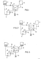
- FIG. 1 illustrates a schematic flow diagram of the apparatus of the invention.
- a container 1 for holding a body cavity fluid removed from a living body, a pump 2 for transporting the body cavity fluid, a . concentrator 3, a filter 4, and a container 5 for holding the concentrated and filtered body cavity fluid are essential elements of the apparatus of the invention and are interconnected by common flow paths.
- the body cavity fluid holding container 1 and the treated body cavity fluid holding container 5 are disposable containers, such as transfusion fluid bags and blood bags made of plasticized polyvinyl chloride.
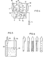
- a container having a means for removing the body cavity fluid from the surface portion of the fluid, such as shown in Fig. 5, is especially preferred, since simultaneous removal of that portion of fibri which has precipitated to the container bottom is reduced, whereby blockage of the concentrator or filter membranes can be prevented.
- sli- element 22 connected to said outlet 21.
- the slit element may be of any form and shape, such as shown in Fig. 6, so long as the body cavity fluid can easily flow into the outlet 21 even when the slit element is in close contact with the main body inside surface.
- the concentrator to be used in the apparatus of the present invention comprises a membrane capable of prohibiting permeation of useful proteins contained in the body cavity flui but allowing permeation of excess water contained in the body cavity fluid.
- Suitable examples of the membrane material which can meet these requirements are those materials known to be useful in artificial kidneys, including membranes made of cuproammonium rayon, ethylene-vinyl alcohol copolymers, polyacrylonitrile, polymethyl methacrylate, polysulfones, cellulose or cellulose derivatives.
- the membrane can have the form of hollow fibers, film, coil or tube, for instance. Preferred are hollow fiber membranes. ' In particular, hollow fibers made of ethylene-vinyl alcohol copyolymers are best suited for use in the concentrator of the present invention because of their treating capacity and processability.
- the filter to be used in accordance with the inventio comprises a membrane capable of allowing permeation of useful substances contained in the body cavity fluid that has been concentrated in the above-mentioned concentrator, such as . proteins (e.g. albumin and globulin), but prohibiting permeation of harmful substances such as bacteria or cancer cells.
- a membrane capable of allowing permeation of useful substances contained in the body cavity fluid that has been concentrated in the above-mentioned concentrator, such as . proteins (e.g. albumin and globulin), but prohibiting permeation of harmful substances such as bacteria or cancer cells.
- membranes are membrane filters having pore sizes of 0.01 to 1 microns and made of cellulose acetate, cellulose esters and the like as well as membranes made of polyvinyl alcohol, polysulfones, polymethyl methacrylates, polypropylene (macroporous membranes), and the like, preferably in the form of hollow fibers. Hollow fibers made of.polyvinyl alcohol are
- Any pump can be used in accordance with the present invention so long as it can circulate' the body cavity fluid and is non-toxic and non-hazardous to the living body.
- Commercially available blood pumps generally have such a function and are suitable for use.
- an exchangeable prefilter in the concentration or filtration flow paths may also be useful.
- Fig. 2 and Fig. 3 illustrate two modes of use of the .body cavity fluid concentration and filtration apparatus of the present invention.
- Fig. 2 illustrates the concentration operation.
- body cavity fluid removed from a body cavity and stored in container 1 can be removed from the container by means of the body cavity fluid take-out pump 2.
- the body cavity fluid passes through a pressure detector 13, and is led to the concentrator 3.
- the removal of the body cavity fluid from the body cavity can be effected either prior to the treatment operation or during the concentration operation.
- the body cavity fluid that has been concentrated in concentrator 3 is returned to the above-mentioned container 1, forming a circulation flow path.
- the flow paths 6 and 7, which connect the above-mentioned body cavity fluid holding container 1 with the inlets of the concentrator 3 and filter 4 and with the outlets thereof each comprises, respectively, a branched tube. While the body cavity fluid is being concentrated, those branches of the branc ed tubes in said flow paths 6 and 7 which are connected to the inlet and outlet of the filter are closed by means of flow path closing means. While such closing means can be of any type, th use of pinch cocks, forceps, clamps or clips, which press the passage-ways from the outside and hold them in the closed state is most convenient. Electrically operable valves can also be used, and in this case, change-over from the concentrator to th E filter can be made automatically by using a timer, for instanc whereby semi-continuous treatment becomes possible.
- the filtration pressure in the concentrator can be adjusted by the pressure detector 13 and a.pressure adjusting means 12 disposed in the flow path 7 connecting the concentrate 3 and the container 1. While an automatic valve operable in association with a pressure meter can be used as such pressure adjusting means, manual adjustment with a commercially available clamp or clip with simultaneous observation of a pressure meter 15 by the eye is generally most convenient. Generally, it is preferred to maintain said pressure at 500 mmHg or below.
- the filtrate coming out of the concentrator discharge into a container 14 through a line 9 connected to the outlet of the concentrator.
- Measurement of the amount of filtrate by using a measuring cylinder as the container 14, for instance, enables comparison between the volume of body cavity fluid before concentration and the filtrate volume in the course of concentration, and thus makes it possible to easily control the degree of concentration of the body cavity fluid to a predetermined value.
- the pressure detector used in the apparatus of the present invention can conveniently be a pressure detector of the type generally used for pressure detection in blood circuits and comprises a pressure meter connected to a drip chamber. Other types of pressure detectors may also be used.
- the body cavity fluid treating apparatus of the present invention may also be fitted, at any point until the body cavity fluid enters the concentrator 3, with a calcium concentration adjustment means using an ion exchange resin or a means for adding heparin, urokinase or sodium citrate for prevention of fibrin formation, as disclosed, for example in Japanese Patent Applications laid open under Nos. 80-76654, 80-86456, 80-91360 and 80-91361.
- Fig. 4 is a front elevation view of one example of the apparatus of the present invention.
- the apparatus comprise a monitoring section 16 with a roller pump 2 for transporting the body cavity fluid, a pressure meter 15, operating switches and an alarm signal device built in, and a graphic panel section 19 illustrating the manner in which the flow paths are converted and the disposition of the filter and concentrator.
- hooks 18 and 18' for suspending a body cavity fluid holding bag 1 and a filtered body cavity fluid concentrate holding bag 5.
- a pressure detector 13 In front of the graphic panel 19, a pressure detector 13, a concentrator 3 and a filter 4 are respectively mounted with holders.
- Flow path 6 commences at the lower end of the body cavity fluid holding bag 1 suspended on the hook 18 and connects with the body cavity fluid inlet, respectively, of the concentrator 3 and the filter 4 by means of a branched tube.
- the pressure detector 13 for detecting the pressure within the flow path. If.an abnormal pressure is detected, the alarm signal device activates and- issues a warning signal and simultaneously stops the body cavity fluid transporting pump, whereby breakage of the concentrator, filter and flow path tubes can be prevented.
- the body cavity fluid outlets of the concentrator 3 and filter 4 are connected with the above-mentioned bag 1 by means of the flow path 7 also comprising a branched tube.
- Flow path 9 connects the filtrate outlet of concentrator 3 with a measuring cylinder 14.
- the filtrate coming from the filter 4, namely the filtered body cavity fluid concentrate is conducted by flow path 8, from the filtrate outlet of said filter to bag 5 for holding the filtered body cavity fluid concentrate.
- the previously mentioned flow path 7 is provided with a forceps or similar clamp means for adjusting the concentration pressure.
- Said apparatus is very compact, for example 600 mm in height, 40 mm in width, 300 mm in depth and 20 kg in weight, and can easily be carried owing to a handle 17 mounted on the top of the apparatus.
- the processes of removing bacteria and unnecessa J cellular components and concentrating useful proteins for intravenous return to the patient can be carried out in a very safe and simple manner.
- this system has other advantages.
- the final filtrate volume can easily be controlled in accordance with a preliminarily calculated value, and a high degree of safety can be secured since bacteria, cance cells and other unnecessary materials are filtered off prior to return of the concentrate to the living body by intravenous infusion.
- the apparatus shown in Fig. 4 was used for treating ascitic fluid.
- the concentrator used comprised 4,000 built-in ethylene vinyl alcohol copolymer hollow fiber pieces (350 micron: in outside diameter, 250 microns in inside diameter, and 220 mm in effective length) capable of allowing permeation of substances having molecular weights less than 40,000.
- the filter used comprised 1,000 built-in polyvinyl alcohol hollow fiber pieces (800 microns in outside diameter, 400 microns in inside diameter, 150 mm in effective length, and 0.20 microns in average pore size).
- ascitic fluid Into a commercial bag for transfusion fluids, there was introduced 3,600 ml of ascitic fluid (with a total protein level of 2.2 g/dl). The ascitic fluid was concentrated by circulating the same at a rate of 100 cc/min. After about 80 minutes, 2,100 ml of a filtrate and 1,500 ml of an about 2.3 times concentrated ascitic fluid were obtained. Then, the flow path was switched over to the filter by means of forceps, and the filtration process was carried out at an average filtration pressure of about 150 mmHg for about 30 minutes. Throughout the above ascitic fluid treatment, no trouble was encountered and the concentration and filtration proceeded smoothly.
Abstract
Description
- This invention relates to a novel apparatus which is capable of treating body cavity fluids very efficiently and safely by the batch-wise concentration of body cavity fluids followed by filtration. The term "body cavity fluids" as used herein includes protein-containing fluids accumulated and retained in body cavities, such as ascitic fluid and pleural fluid.
- There are a considerable number of patients who are suffering from hydrops of body cavities, such as ascites and hydrothorax, resulting from cirrhosis, renal failure or cancer of the viscera, among others. Recently, an apparatus for filtering and concentrating ascitic fluid for returning the concentrate intravenously to the patient has been proposed (see, for example, Japanese Patent Publication No. 90-15221). In such apparatus, ascitic fluid withdrawn from the abdominal cavity of an ascitic patient is filtered through a hollow fiber filter whereby cancer cells or bacteria are removed. The filtrate ascitic fluid is then concentrated by means of a hollow fiber concentrator to increase the concentration of useful proteins, and the resulting concentrated ascitic fluid is returned intravenously to the patient. This type of apparatus was developed to provide a safer system capable of overcoming the deficiencies of the prior art ascitic fluid-concentrating apparatus wherein, when unnecessary material such as bacteria and giant cells were present in the ascitic fluid, these too However, there are further disadvantages associated with the above-mentioned ascitic fluid filtering and concentrating apparatus in that complicated control mechanisms are required for associated control of filtration and concentration and for control of the rate of concentration; and still further, two or more pumps are required so that the apparatus is complicated, troublesome to operate, large-sized and expensive.
- It is an object of the invention to overcome the disadvantages of the above-mentioned apparatus and provide a body cavity fluid treating apparatus which can be handled and operated in a simple and easy manner. Another object is to provide a small-sized and inexpensive body cavity fluid treat-. ing apparatus.
- In the accompanying drawings,
- Fig. 1 is a schematic illustration of an embodiment of the body cavity fluid treating apparatus of the present invention;
- Fig. 2 is a schematic illustration of one mode of operation of the apparatus wherein a body cavity fluid is being concentrated in said body cavity fluid treating apparatus;
- Fig. 3 is a schematic illustration of another mode of operation wherein a body cavity fluid is being filtered through a filter;
- Fig. 4 is a front elevation of one embodiment of the body cavity fluid treating apparatus of the present invention;
- Fig. 5 is a schematic illustration of a preferred example of the body cavity fluid holding container to be used in the body cavity fluid treating apparatus of the present invention; and
- Fig. 6 illustrates several examples of the slit element to be used in body cavity fluid holding containers such as shown in Fig. 5.
- The present invention provides a body cavity fluid treating apparatus which comprises a first container for holding a body cavity fluid, a second container-for holding a concentrated body cavity fluid freed from bacteria, a pump for drawing out the body cavity fluid from the first container, a concentrator for concentrating the body cavity fluid, a filter for filtering the body. cavity fluid which has been concentrated in said concentrator, a first flow path connecting the first container with the body cavity fluid inlet of the concentrator and with the body cavity fluid inlet of the filter by means of a branched tube, a second flow path connecting the body cavity fluid outlet of the concentrator and the body cavity fluid outlet of the filter respectively with the first container by means of a branched tube, a third flow path connecting the filtrate outlet of the filter with the second container, a fourth flow path connected to the filtrate outlet of the concentrator, means for closing, during the period of body cavity fluid con- .centration, those branches of the branched tubes in the first and second flow paths which are connected to the inlet and outlet of the filter, respectively, and closing, during the period of body cavity fluid filtration, those branches of the branched tubes in said same flow paths which are connected to the inlet and outlet of the concentrator, respectively, and a pressure regulating means provided in said second flow path.
- A novel feature of the present invention consists in batch-wise body cavity fluid concentration and filtration. Employment of such batch-wise treatment has made if possible t provide an apparatus which is easy to use, simple to operate and free from errors.
- Another novel feature of the invention lies in that concentration is performed prior to filtration; whereas, in th prior art, filtration precedes concentration. Thus, the invention has made it possible to utilize common flow paths for concentration and filtration which is impossible in the prior art apparatus. In accordance with the present invention, only one pump is required, consequently the apparatus is small-sizec and inexpensive, and troublesome operation, one of the great drawbacks heretofore. associated with this kind of apparatus, is greatly reduced.
- Referring to the drawings, Fig. 1 illustrates a schematic flow diagram of the apparatus of the invention. A
container 1 for holding a body cavity fluid removed from a living body, apump 2 for transporting the body cavity fluid, a .concentrator 3, a filter 4, and acontainer 5 for holding the concentrated and filtered body cavity fluid are essential elements of the apparatus of the invention and are interconnected by common flow paths. - It is preferred for reasons of convenience in use and safety that the body cavity
fluid holding container 1 and the treated body cavityfluid holding container 5 are disposable containers, such as transfusion fluid bags and blood bags made of plasticized polyvinyl chloride. In addition to such commercially available bags for medical use, a container having a means for removing the body cavity fluid from the surface portion of the fluid, such as shown in Fig. 5, is especially preferred, since simultaneous removal of that portion of fibri which has precipitated to the container bottom is reduced, whereby blockage of the concentrator or filter membranes can be prevented. Themain body 20 of the container shown in Fig. is made of a flexible material, such as a polyvinyl chloride, polyethylene or polypropylene film or sheet, and bodycavity fluid outlet 21 andinlet 23 are disposed in the upper part of said main body. Within the main body, there is disposed a sli-element 22 connected to saidoutlet 21. The slit element may be of any form and shape, such as shown in Fig. 6, so long as the body cavity fluid can easily flow into theoutlet 21 even when the slit element is in close contact with the main body inside surface. When the body cavity fluid is taken out of the container, that part of the main body of the container whic is situated above the fluid level surface collapses under the negative pressure in the container and thereby comes into close contact with the slit element, whereby a passage-way for the body cavity fluid is formed and the fluid is always taken out from the fluid surface portion. Therefore, the fibrin precipitate remains on the bottom and scarcely flows out into the flow path. - The concentrator to be used in the apparatus of the present invention comprises a membrane capable of prohibiting permeation of useful proteins contained in the body cavity flui but allowing permeation of excess water contained in the body cavity fluid. Suitable examples of the membrane material which can meet these requirements are those materials known to be useful in artificial kidneys, including membranes made of cuproammonium rayon, ethylene-vinyl alcohol copolymers, polyacrylonitrile, polymethyl methacrylate, polysulfones, cellulose or cellulose derivatives. The membrane can have the form of hollow fibers, film, coil or tube, for instance. Preferred are hollow fiber membranes. ' In particular, hollow fibers made of ethylene-vinyl alcohol copyolymers are best suited for use in the concentrator of the present invention because of their treating capacity and processability.
- The filter to be used in accordance with the inventio comprises a membrane capable of allowing permeation of useful substances contained in the body cavity fluid that has been concentrated in the above-mentioned concentrator, such as . proteins (e.g. albumin and globulin), but prohibiting permeation of harmful substances such as bacteria or cancer cells. Examples of such membranes are membrane filters having pore sizes of 0.01 to 1 microns and made of cellulose acetate, cellulose esters and the like as well as membranes made of polyvinyl alcohol, polysulfones, polymethyl methacrylates, polypropylene (macroporous membranes), and the like, preferably in the form of hollow fibers. Hollow fibers made of.polyvinyl alcohol are especially preferred.
- Any pump can be used in accordance with the present invention so long as it can circulate' the body cavity fluid and is non-toxic and non-hazardous to the living body. Commercially available blood pumps generally have such a function and are suitable for use.
- In some cases, the use of an exchangeable prefilter in the concentration or filtration flow paths may also be useful.
- Fig. 2 and Fig. 3 illustrate two modes of use of the .body cavity fluid concentration and filtration apparatus of the present invention.
- Fig. 2 illustrates the concentration operation. As mentioned previously, body cavity fluid removed from a body cavity and stored in
container 1 can be removed from the container by means of the body cavity fluid take-outpump 2. The body cavity fluid passes through apressure detector 13, and is led to theconcentrator 3. The removal of the body cavity fluid from the body cavity can be effected either prior to the treatment operation or during the concentration operation. The body cavity fluid that has been concentrated inconcentrator 3 is returned to the above-mentionedcontainer 1, forming a circulation flow path. - The
flow paths fluid holding container 1 with the inlets of theconcentrator 3 and filter 4 and with the outlets thereof each comprises, respectively, a branched tube. While the body cavity fluid is being concentrated, those branches of the branc ed tubes in saidflow paths - The filtration pressure in the concentrator can be adjusted by the
pressure detector 13 and a.pressure adjusting means 12 disposed in theflow path 7 connecting theconcentrate 3 and thecontainer 1. While an automatic valve operable in association with a pressure meter can be used as such pressure adjusting means, manual adjustment with a commercially available clamp or clip with simultaneous observation of apressure meter 15 by the eye is generally most convenient. Generally, it is preferred to maintain said pressure at 500 mmHg or below. - The filtrate coming out of the concentrator discharge into a
container 14 through aline 9 connected to the outlet of the concentrator. Measurement of the amount of filtrate by using a measuring cylinder as thecontainer 14, for instance, enables comparison between the volume of body cavity fluid before concentration and the filtrate volume in the course of concentration, and thus makes it possible to easily control the degree of concentration of the body cavity fluid to a predetermined value. - Naturally, it is also possible to employ a vacuum pump in the flow path on the outlet side of the concentrator or use a suction line generally installed at the hospital bedside and thereby perform the concentration procedure under subatmospheric pressure.
- When the predetermined degree of concentration is attained by recycling the body cavity fluid through the above-mentioned flow path for concentration, those branches of the branched tubes which are connected to the body cavity fluid inlet and outlet of the
concentrator 3 are closed by means ofpinch cocks 11, for instance, whereas the closing means 10 dis posed on the branches connected to the body cavity fluid inlet and outlet of the filter 4 are removed. Thereafter, the concentrated body cavity fluid stored in thecontainer 1 is remov by means of thepump 2, for commencement of the filtration process (cf. Fig. 3). The filtered body cavity fluid concentrate passes through aflow path 8 connected to the filtrate outlet to thecontainer 5 and is stored therein. The filtration pressure in the filter can be detected by thepressure detector 13 used during the concentration step. - The pressure detector used in the apparatus of the present invention can conveniently be a pressure detector of the type generally used for pressure detection in blood circuits and comprises a pressure meter connected to a drip chamber. Other types of pressure detectors may also be used.
- The body cavity fluid treating apparatus of the present invention may also be fitted, at any point until the body cavity fluid enters the
concentrator 3, with a calcium concentration adjustment means using an ion exchange resin or a means for adding heparin, urokinase or sodium citrate for prevention of fibrin formation, as disclosed, for example in Japanese Patent Applications laid open under Nos. 80-76654, 80-86456, 80-91360 and 80-91361. - Fig. 4 is a front elevation view of one example of the apparatus of the present invention. The apparatus comprise a
monitoring section 16 with aroller pump 2 for transporting the body cavity fluid, apressure meter 15, operating switches and an alarm signal device built in, and agraphic panel section 19 illustrating the manner in which the flow paths are converted and the disposition of the filter and concentrator. - At both ends of the upper side of the
graphic panel 19, there are providedhooks 18 and 18' for suspending a body cavityfluid holding bag 1 and a filtered body cavity fluidconcentrate holding bag 5. In front of thegraphic panel 19, apressure detector 13, aconcentrator 3 and a filter 4 are respectively mounted with holders. - Flow
path 6 commences at the lower end of the body cavityfluid holding bag 1 suspended on thehook 18 and connects with the body cavity fluid inlet, respectively, of theconcentrator 3 and the filter 4 by means of a branched tube. In saidflow path 6, there is provided thepressure detector 13 for detecting the pressure within the flow path..If.an abnormal pressure is detected, the alarm signal device activates and- issues a warning signal and simultaneously stops the body cavity fluid transporting pump, whereby breakage of the concentrator, filter and flow path tubes can be prevented. The body cavity fluid outlets of theconcentrator 3 and filter 4 are connected with the above-mentionedbag 1 by means of theflow path 7 also comprising a branched tube. Flowpath 9 connects the filtrate outlet ofconcentrator 3 with a measuringcylinder 14. On the other hand, the filtrate coming from the filter 4, namely the filtered body cavity fluid concentrate, is conducted byflow path 8, from the filtrate outlet of said filter tobag 5 for holding the filtered body cavity fluid concentrate. The previously mentionedflow path 7 is provided with a forceps or similar clamp means for adjusting the concentration pressure. Said apparatus is very compact, for example 600 mm in height, 40 mm in width, 300 mm in depth and 20 kg in weight, and can easily be carried owing to ahandle 17 mounted on the top of the apparatus. - By using the above-mentioned apparatus of the present invention for batch-wise concentration and filtration of body cavity fluids, the processes of removing bacteria and unnecessaJ cellular components and concentrating useful proteins for intravenous return to the patient can be carried out in a very safe and simple manner. Moreover, this system has other advantages. Thus, for example, the final filtrate volume can easily be controlled in accordance with a preliminarily calculated value, and a high degree of safety can be secured since bacteria, cance cells and other unnecessary materials are filtered off prior to return of the concentrate to the living body by intravenous infusion.
- The present invention is further illustrated in more detail.by the following example, which is by no means limitative of the present invention-EXAMPLE
- The apparatus shown in Fig. 4 was used for treating ascitic fluid. The concentrator used comprised 4,000 built-in ethylene vinyl alcohol copolymer hollow fiber pieces (350 micron: in outside diameter, 250 microns in inside diameter, and 220 mm in effective length) capable of allowing permeation of substances having molecular weights less than 40,000. The filter used comprised 1,000 built-in polyvinyl alcohol hollow fiber pieces (800 microns in outside diameter, 400 microns in inside diameter, 150 mm in effective length, and 0.20 microns in average pore size).
- Into a commercial bag for transfusion fluids, there was introduced 3,600 ml of ascitic fluid (with a total protein level of 2.2 g/dl). The ascitic fluid was concentrated by circulating the same at a rate of 100 cc/min. After about 80 minutes, 2,100 ml of a filtrate and 1,500 ml of an about 2.3 times concentrated ascitic fluid were obtained. Then, the flow path was switched over to the filter by means of forceps, and the filtration process was carried out at an average filtration pressure of about 150 mmHg for about 30 minutes. Throughout the above ascitic fluid treatment, no trouble was encountered and the concentration and filtration proceeded smoothly.
Claims (5)
Applications Claiming Priority (2)
| Application Number | Priority Date | Filing Date | Title |
|---|---|---|---|
| JP107331/80 | 1980-08-04 | ||
| JP10733180A JPS5731867A (en) | 1980-08-04 | 1980-08-04 | Concentrating filtering device for body fluid |
Publications (3)
| Publication Number | Publication Date |
|---|---|
| EP0045515A2 true EP0045515A2 (en) | 1982-02-10 |
| EP0045515A3 EP0045515A3 (en) | 1982-02-17 |
| EP0045515B1 EP0045515B1 (en) | 1985-04-24 |
Family
ID=14456335
Family Applications (1)
| Application Number | Title | Priority Date | Filing Date |
|---|---|---|---|
| EP81106106A Expired EP0045515B1 (en) | 1980-08-04 | 1981-08-04 | Apparatus for concentrating and filtering body cavity fluids |
Country Status (4)
| Country | Link |
|---|---|
| US (1) | US4416772A (en) |
| EP (1) | EP0045515B1 (en) |
| JP (1) | JPS5731867A (en) |
| DE (1) | DE3170128D1 (en) |
Cited By (1)
| Publication number | Priority date | Publication date | Assignee | Title |
|---|---|---|---|---|
| FR2695037A1 (en) * | 1992-09-02 | 1994-03-04 | Pall Corp | Method and apparatus for removing unwanted fluids from treated blood products. |
Families Citing this family (16)
| Publication number | Priority date | Publication date | Assignee | Title |
|---|---|---|---|---|
| WO1988009370A1 (en) * | 1983-09-06 | 1988-12-01 | Ghose Rabindra N | Separation of specific biological substances by a biochemical filter |
| US4692411A (en) * | 1983-09-06 | 1987-09-08 | Ghose Rabindra N | Separation of specific biological cells by a biochemical filter |
| US4721564A (en) * | 1985-10-22 | 1988-01-26 | Kuraray Co., Ltd. | Apparatus for the filtration of plasma from blood |
| US4810389A (en) * | 1987-03-02 | 1989-03-07 | Westinghouse Electric Corp. | Filtration system |
| IT1217332B (en) * | 1988-02-02 | 1990-03-22 | Dideco Spa | PROCEDURE FOR THE EXTRA-BODY TREATMENT OF ASCITIC LIQUID |
| JPH0696098B2 (en) * | 1988-05-27 | 1994-11-30 | 株式会社クラレ | Hollow fiber type fluid treatment equipment |
| CA2083075A1 (en) * | 1992-06-10 | 1993-12-11 | Vlado I. Matkovich | System for treating transition zone material |
| US5670060A (en) * | 1992-06-10 | 1997-09-23 | Pall Corporation | Method for treating a biological fluid including transition zone material |
| US5520885A (en) * | 1993-01-19 | 1996-05-28 | Thermogenesis Corporation | Fibrinogen processing apparatus, method and container |
| JPH0764018A (en) * | 1993-08-27 | 1995-03-10 | Toko Inc | Laser pointer |
| US5961834A (en) * | 1996-12-23 | 1999-10-05 | Bio-Rad Laboratories, Inc. | Simple micro method for concentration and desalting utilizing a hollow fiber, with special reference to capillary electrophoresis |
| US6994790B2 (en) * | 2002-02-01 | 2006-02-07 | Gambro, Inc. | Whole blood collection and processing method |
| US7488757B2 (en) * | 2003-03-24 | 2009-02-10 | Becton, Dickinson And Company | Invisible antimicrobial glove and hand antiseptic |
| US7604607B2 (en) * | 2003-09-29 | 2009-10-20 | Bausch & Lomb Incorporated | Peristaltic pump fitment for attachment to an aspirant collection bag |
| JP5249973B2 (en) * | 2010-02-25 | 2013-07-31 | 圭祐 松崎 | Ascites treatment system and cleaning method thereof |
| TWI794706B (en) * | 2019-12-27 | 2023-03-01 | 日商旭化成醫療股份有限公司 | Test solution for evaluating protein recovery performance of body cavity fluid concentrator and manufacturing method thereof |
Citations (3)
| Publication number | Priority date | Publication date | Assignee | Title |
|---|---|---|---|---|
| DE2150838A1 (en) * | 1970-10-12 | 1972-04-13 | Rhone Poulenc Sa | Device for the concentration of a liquid containing non-ultrafilterable components |
| US3977967A (en) * | 1973-05-10 | 1976-08-31 | Union Carbide Corporation | Ultrafiltration apparatus and process for the treatment of liquids |
| DE2659690A1 (en) * | 1976-12-31 | 1978-07-20 | Kernforschungsz Karlsruhe | Multistage dialysis appts. with valves between cells - to permit various permutations giving constant sepn. level |
Family Cites Families (6)
| Publication number | Priority date | Publication date | Assignee | Title |
|---|---|---|---|---|
| US3799873A (en) * | 1968-04-19 | 1974-03-26 | Hydronautics | Artificial kidney |
| US3648698A (en) * | 1969-05-23 | 1972-03-14 | George O Doherty | Surgical collection unit |
| US4190047A (en) * | 1977-08-26 | 1980-02-26 | University Of Utah | Method and apparatus for peritoneal dialysis |
| DE2755214C3 (en) * | 1977-12-10 | 1980-12-11 | Dr. Eduard Fresenius Chemisch-Pharmazeutische Industrie Kg Apparatebau Kg, 6380 Bad Homburg | Device for periodic irrigation of the abdominal cavity |
| IT1174707B (en) * | 1978-05-03 | 1987-07-01 | Bonomini Vittorio | PORTABLE ARTIFICIAL KIDNEY FOR DIALYSIS |
| US4311587A (en) * | 1979-12-10 | 1982-01-19 | Japan Foundation For Artificial Organs | Filter arrangement denying bacteria entry to peritoneum |
-
1980
- 1980-08-04 JP JP10733180A patent/JPS5731867A/en active Granted
-
1981
- 1981-07-24 US US06/286,625 patent/US4416772A/en not_active Expired - Fee Related
- 1981-08-04 EP EP81106106A patent/EP0045515B1/en not_active Expired
- 1981-08-04 DE DE8181106106T patent/DE3170128D1/en not_active Expired
Patent Citations (3)
| Publication number | Priority date | Publication date | Assignee | Title |
|---|---|---|---|---|
| DE2150838A1 (en) * | 1970-10-12 | 1972-04-13 | Rhone Poulenc Sa | Device for the concentration of a liquid containing non-ultrafilterable components |
| US3977967A (en) * | 1973-05-10 | 1976-08-31 | Union Carbide Corporation | Ultrafiltration apparatus and process for the treatment of liquids |
| DE2659690A1 (en) * | 1976-12-31 | 1978-07-20 | Kernforschungsz Karlsruhe | Multistage dialysis appts. with valves between cells - to permit various permutations giving constant sepn. level |
Non-Patent Citations (1)
| Title |
|---|
| La Recherche. No. 41, January 1974 Vol. 5, pages 33-43 J. NEEL: "Les Membranes Artificielles" page 35, figure 1, lines 29-31 * * |
Cited By (5)
| Publication number | Priority date | Publication date | Assignee | Title |
|---|---|---|---|---|
| FR2695037A1 (en) * | 1992-09-02 | 1994-03-04 | Pall Corp | Method and apparatus for removing unwanted fluids from treated blood products. |
| WO1994005344A1 (en) * | 1992-09-02 | 1994-03-17 | Pall Corporation | Process and apparatus for removal of unwanted fluids from processed blood products |
| BE1007362A4 (en) * | 1992-09-02 | 1995-05-30 | Pall Corp | Method and apparatus for separation of fluids blood products processed side. |
| DE4394276T1 (en) * | 1992-09-02 | 1995-10-19 | Pall Corp | Remove unwanted fluids from treated blood products |
| DE4394276C2 (en) * | 1992-09-02 | 1999-03-04 | Pall Corp | Method and device for removing unwanted fluids from treated blood products |
Also Published As
| Publication number | Publication date |
|---|---|
| JPS5731867A (en) | 1982-02-20 |
| US4416772A (en) | 1983-11-22 |
| DE3170128D1 (en) | 1985-05-30 |
| EP0045515A3 (en) | 1982-02-17 |
| EP0045515B1 (en) | 1985-04-24 |
| JPS6113823B2 (en) | 1986-04-15 |
Similar Documents
| Publication | Publication Date | Title |
|---|---|---|
| US4416772A (en) | Apparatus for concentrating and filtering body cavity fluids | |
| EP0594783B1 (en) | Autotransfusion membrane system | |
| US4713171A (en) | Apparatus for removing water from blood | |
| EP0588965B1 (en) | Collection device | |
| US5407425A (en) | System for the collecting and retransfusion of autologous blood | |
| US4687580A (en) | Membrane apparatus/process adapted for plasmapheresis | |
| JPS6085757A (en) | Serum extracting method and apparatus especially useful in said method | |
| EP0156496B1 (en) | Apparatus for the treatment of plasma | |
| US20060011545A1 (en) | Method and device for separating whole blood under gravitational force | |
| JPS6075063A (en) | Serum lead-out method and equipment especially useful therein | |
| IL45019A (en) | Blood reservoir for use in surgical procedures | |
| JPH0152026B2 (en) | ||
| GB2277464A (en) | Positioning of filter assembly in centrifugal processing of biological fluids | |
| EP0518975A1 (en) | Autologous blood recovery membrane system and method. | |
| US5004548A (en) | Method and apparatus for rinsing and priming an exchanger | |
| KR20010090845A (en) | Method and apparatus for preventing protein loss with peritoneal dialysis | |
| US7722561B2 (en) | Peritoneal dialyzer and method of peritoneal dialysis | |
| JP3066151B2 (en) | Ascites treatment equipment | |
| JP3257613B2 (en) | Dialysis fluid management device for hemodialysis machine | |
| JPS61143068A (en) | Blood dialytic method and apparatus | |
| JP3353467B2 (en) | Dialysis fluid management device for hemodialysis machine | |
| JPH05220219A (en) | Ascites treating device | |
| JPS6127062B2 (en) | ||
| JPH0628135Y2 (en) | Autologous blood recovery device | |
| JPS609459B2 (en) | Ascitic fluid concentrator |
Legal Events
| Date | Code | Title | Description |
|---|---|---|---|
| PUAI | Public reference made under article 153(3) epc to a published international application that has entered the european phase |
Free format text: ORIGINAL CODE: 0009012 |
|
| PUAL | Search report despatched |
Free format text: ORIGINAL CODE: 0009013 |
|
| AK | Designated contracting states |
Designated state(s): DE FR IT |
|
| AK | Designated contracting states |
Designated state(s): DE FR IT |
|
| 17P | Request for examination filed |
Effective date: 19820308 |
|
| ITF | It: translation for a ep patent filed |
Owner name: MODIANO & ASSOCIATI S.R.L. |
|
| GRAA | (expected) grant |
Free format text: ORIGINAL CODE: 0009210 |
|
| AK | Designated contracting states |
Designated state(s): DE FR IT |
|
| REF | Corresponds to: |
Ref document number: 3170128 Country of ref document: DE Date of ref document: 19850530 |
|
| ET | Fr: translation filed | ||
| PLBE | No opposition filed within time limit |
Free format text: ORIGINAL CODE: 0009261 |
|
| STAA | Information on the status of an ep patent application or granted ep patent |
Free format text: STATUS: NO OPPOSITION FILED WITHIN TIME LIMIT |
|
| 26N | No opposition filed | ||
| PGFP | Annual fee paid to national office [announced via postgrant information from national office to epo] |
Ref country code: FR Payment date: 19900807 Year of fee payment: 10 |
|
| ITTA | It: last paid annual fee | ||
| PGFP | Annual fee paid to national office [announced via postgrant information from national office to epo] |
Ref country code: DE Payment date: 19900927 Year of fee payment: 10 |
|
| PG25 | Lapsed in a contracting state [announced via postgrant information from national office to epo] |
Ref country code: FR Effective date: 19920430 |
|
| PG25 | Lapsed in a contracting state [announced via postgrant information from national office to epo] |
Ref country code: DE Effective date: 19920501 |
|
| REG | Reference to a national code |
Ref country code: FR Ref legal event code: ST |