EP0048010A1 - Procédé de fabrication de couches-culottes à jeter et couches-culottes obtenues par la mise en oeuvre de ce procédé - Google Patents
Procédé de fabrication de couches-culottes à jeter et couches-culottes obtenues par la mise en oeuvre de ce procédé Download PDFInfo
- Publication number
- EP0048010A1 EP0048010A1 EP81107223A EP81107223A EP0048010A1 EP 0048010 A1 EP0048010 A1 EP 0048010A1 EP 81107223 A EP81107223 A EP 81107223A EP 81107223 A EP81107223 A EP 81107223A EP 0048010 A1 EP0048010 A1 EP 0048010A1
- Authority
- EP
- European Patent Office
- Prior art keywords
- elastic
- sheet
- manufacturing
- impermeable
- diapers
- Prior art date
- Legal status (The legal status is an assumption and is not a legal conclusion. Google has not performed a legal analysis and makes no representation as to the accuracy of the status listed.)
- Granted
Links
Images


Classifications
-
- A—HUMAN NECESSITIES
- A61—MEDICAL OR VETERINARY SCIENCE; HYGIENE
- A61F—FILTERS IMPLANTABLE INTO BLOOD VESSELS; PROSTHESES; DEVICES PROVIDING PATENCY TO, OR PREVENTING COLLAPSING OF, TUBULAR STRUCTURES OF THE BODY, e.g. STENTS; ORTHOPAEDIC, NURSING OR CONTRACEPTIVE DEVICES; FOMENTATION; TREATMENT OR PROTECTION OF EYES OR EARS; BANDAGES, DRESSINGS OR ABSORBENT PADS; FIRST-AID KITS
- A61F13/00—Bandages or dressings; Absorbent pads
- A61F13/15—Absorbent pads, e.g. sanitary towels, swabs or tampons for external or internal application to the body; Supporting or fastening means therefor; Tampon applicators
- A61F13/45—Absorbent pads, e.g. sanitary towels, swabs or tampons for external or internal application to the body; Supporting or fastening means therefor; Tampon applicators characterised by the shape
- A61F13/49—Absorbent articles specially adapted to be worn around the waist, e.g. diapers
- A61F13/49007—Form-fitting, self-adjusting disposable diapers
- A61F13/49009—Form-fitting, self-adjusting disposable diapers with elastic means
- A61F13/49017—Form-fitting, self-adjusting disposable diapers with elastic means the elastic means being located at the crotch region
-
- A—HUMAN NECESSITIES
- A61—MEDICAL OR VETERINARY SCIENCE; HYGIENE
- A61F—FILTERS IMPLANTABLE INTO BLOOD VESSELS; PROSTHESES; DEVICES PROVIDING PATENCY TO, OR PREVENTING COLLAPSING OF, TUBULAR STRUCTURES OF THE BODY, e.g. STENTS; ORTHOPAEDIC, NURSING OR CONTRACEPTIVE DEVICES; FOMENTATION; TREATMENT OR PROTECTION OF EYES OR EARS; BANDAGES, DRESSINGS OR ABSORBENT PADS; FIRST-AID KITS
- A61F13/00—Bandages or dressings; Absorbent pads
- A61F13/15—Absorbent pads, e.g. sanitary towels, swabs or tampons for external or internal application to the body; Supporting or fastening means therefor; Tampon applicators
- A61F13/15577—Apparatus or processes for manufacturing
- A61F13/15585—Apparatus or processes for manufacturing of babies' napkins, e.g. diapers
- A61F13/15593—Apparatus or processes for manufacturing of babies' napkins, e.g. diapers having elastic ribbons fixed thereto; Devices for applying the ribbons
- A61F13/15609—Apparatus or processes for manufacturing of babies' napkins, e.g. diapers having elastic ribbons fixed thereto; Devices for applying the ribbons the ribbons being applied in an irregular path
-
- B—PERFORMING OPERATIONS; TRANSPORTING
- B05—SPRAYING OR ATOMISING IN GENERAL; APPLYING FLUENT MATERIALS TO SURFACES, IN GENERAL
- B05C—APPARATUS FOR APPLYING FLUENT MATERIALS TO SURFACES, IN GENERAL
- B05C5/00—Apparatus in which liquid or other fluent material is projected, poured or allowed to flow on to the surface of the work
- B05C5/02—Apparatus in which liquid or other fluent material is projected, poured or allowed to flow on to the surface of the work the liquid or other fluent material being discharged through an outlet orifice by pressure, e.g. from an outlet device in contact or almost in contact, with the work
- B05C5/0241—Apparatus in which liquid or other fluent material is projected, poured or allowed to flow on to the surface of the work the liquid or other fluent material being discharged through an outlet orifice by pressure, e.g. from an outlet device in contact or almost in contact, with the work for applying liquid or other fluent material to elongated work, e.g. wires, cables, tubes
-
- B—PERFORMING OPERATIONS; TRANSPORTING
- B05—SPRAYING OR ATOMISING IN GENERAL; APPLYING FLUENT MATERIALS TO SURFACES, IN GENERAL
- B05C—APPARATUS FOR APPLYING FLUENT MATERIALS TO SURFACES, IN GENERAL
- B05C11/00—Component parts, details or accessories not specifically provided for in groups B05C1/00 - B05C9/00
- B05C11/10—Storage, supply or control of liquid or other fluent material; Recovery of excess liquid or other fluent material
- B05C11/1002—Means for controlling supply, i.e. flow or pressure, of liquid or other fluent material to the applying apparatus, e.g. valves
- B05C11/1034—Means for controlling supply, i.e. flow or pressure, of liquid or other fluent material to the applying apparatus, e.g. valves specially designed for conducting intermittent application of small quantities, e.g. drops, of coating material
Definitions
- the present invention relates to a method of manufacturing disposable diapers having cutouts for the passage of the legs of curvilinear shape and provided on at least part of their internal periphery with elastic elements improving the tightness of the passage of the legs .
- the invention also relates to the diapers obtained by the implementation of the method of the invention. These diapers can be discarded after use and can be used for young children or for incontinent adults. They comprise an external waterproof sheet, an absorbent cushion forming an integral part of the assembly and preferably a permeable veil forming an internal coating of the diaper.
- Disposable diapers of this type having an elastic ribbon on the edge of the curvilinear contour of the passage of the legs as described in French patent 2,063,794 can only be produced by means which are unsuitable for manufacturing at high speed. and in particular by sewing elastic threads or ribbons.
- the subject of the present invention is a manufacturing process which allows this type of disposable diaper to be produced in a simple manner and at high speed, comprising elastic elements bordering the curvilinear outline of the leg passages, thereby improving the tightness at this location. while keeping the shape of the legs close to the user's anatomy.
- the continuous manufacturing method according to the invention allows the production of disposable diapers comprising an absorbent cushion disposed between an outer envelope impermeable to moisture and a permeable inner veil, the assembly comprising cutouts of curvilinear profile to allow the passage of legs, these cutouts being provided on the internal periphery of elastic elements.
- an hot melt adhesive is deposited intermittently on the face of an elastic strip moving in the stretched state and intended to come into contact with a continuous flexible sheet. of a heat-sealable material impermeable to moisture.
- the point of contact between the glued elastic strip and the moving impermeable sheet is then moved periodically in a direction transverse to the movement of said waterproof sheet.
- a crotch elastic of curved shape is obtained, glued in the stretched state along at least one curved portion of each leg passage cutout.
- the impermeable sheet is preferably passed over the periphery of a rotary drum held at a relatively low temperature compared to the temperature of the molten adhesive.
- the choice of the temperature of the rotary drum can easily be made by the technician taking into account the parameters that constitute the mass of said drum, the mass of the adhesive per unit length of the elastic strip, the temperature of the adhesive immediately before the contact, the nature of the adhesive and the desired curvature of the crotch elastic.
- the temperature difference between the adhesive deposited and the outer surface of the rotary drum should be sufficient to cause an immediate bonding effect capable of withstanding the transverse forces to which the strip is subjected given the displacement of the contact point. .
- a temperature difference of at least 20 ° C is necessary and preferably from 70 ° C to 130 ° C.
- the point of contact between the elastic strip and the flexible impermeable sheet is preferably kept fixed intermittently so as to define straight non-bonded portions of elastic strip separating the curvilinear bonded portions.
- the displacement in the transverse direction of the initial point of contact between the elastic strip and the flexible impermeable sheet can be done by any suitable means.
- the stretched elastic strip is passed over a guide means such as a possibly curved slide or a grooved pulley mounted in the immediate vicinity of the periphery of the rotary drum, over a carriage capable of moving in parallel to the axis of the drum in an alternative translational movement.
- the guide means may include means for holding the strip lette such as edges or suction holes to prevent the elastic strip from escaping from the guide means during its movement. This movement can be controlled for example by a cam device and indexed on the rotation of the drum so that the curvilinear portions of the elastic strips are produced in the appropriate places on the impermeable sheet.
- the method of the invention can be applied to the production of diapers obtained by transverse cutting of the continuous waterproof sheet.
- the absorbent cushions of elongated shape are arranged along the longitudinal axis of the impermeable sheet and the cuts are made on the longitudinal edges of the composite strip formed by the impermeable sheet, the cushion absorbing the permeable inner veil.
- the method of the invention can also be applied to the production of diapers comprising a link, preferably elastic and continuous, arranged at the waist.
- the absorbent cushions of elongated shape are arranged perpendicular to the longitudinal axis of the waterproof sheet and the cutouts for passage of the legs are made in the form of openings aligned along the longitudinal axis and symmetrical with respect to a direction. transverse.
- the diapers are then obtained by subsequent folding along the longitudinal axis of the composite strip followed by cutting accompanied by simultaneous welding along the transverse axis of symmetry of the openings.
- the present invention also relates to the disposable panty layer obtained according to the method of the invention.
- Such a disposable diaper comprises an absorbent cushion disposed between an outer envelope impermeable to moisture and a permeable inner veil, the assembly comprising cutouts of curvilinear profile to allow the passage of the legs, provided on their internal periphery with elastic elements.
- the diaper made according to the method of the invention comprises curvilinear crotch elastics glued along at least one curved portion of each leg passage cutout.
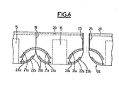
- FIG. 6 shows the final manufacturing stage in the variant of FIG. 5.
- the installation for implementing the method of the invention comprises a rotary drum 1 on which is wound a continuous flexible sheet 2 of a thermo material -welding impermeable to moisture such as polyethylene.
- the drum 1 is rotated in the direction of the arrow 3 so that the sheet 2 marries on about half of its periphery the rotary drum 1.
- the drum 1 is kept at a relatively low temperature of the order of 20 ° vs. Maintaining this temperature can be obtained by forced artificial cooling inside the drum or simply by using a drum of sufficient mass.
- Two elastic strips 4 of small width made for example of latex are stored in containers 5.
- the elastic strips 4 pass after extraction of the containers 5 on a guide roller 5a then between two tension rollers 6 driven in rotation so that the speed of linear movement of the elastic strip 4 at the outlet tension rollers 6 is less than the peripheral speed of the impermeable sheet 2 on the rotary drum 1.
- the desired elongation is obtained in the elastic strip 4.
- An adhesive material at high temperature for example of the order of 100 ° C. to 150 ° C., rendered liquid by fusion (hot melt) is delivered intermittently by the nozzle 7 in the form of a fine line on the surface of the elastic strip 4 intended to come into contact with the impermeable sheet 2.
- a valve not shown in the figure, makes it possible to automatically stop, for determined periods of time, the supply of adhesive material.
- the elastic strip 4 possibly coated with a line of adhesive material then passes inside a fixed guide member 8 then on a grooved pulley 9 mounted on a movable carriage 10 which can slide on a slide 11 under the action control members not shown in the figures which may for example include cams or the like.
- the elastic strip 4 comes into contact with the impermeable sheet 2 at the periphery of the rotary drum 3, the contact point being referenced 12 in the figures.
- the grooved pulley 9 is disposed in the immediate vicinity of the periphery of the rotary drum 3.
- the contact point 12 is slightly downstream of half of the peripheral path of the impermeable sheet 2 on the rotary drum.
- the elastic strip 4 is directed from the grooved pulley 9 to in contact with the impermeable sheet 2 located on the periphery of the rotary drum 3 in a tangent direction relative to the profile of the rotary drum 3.
- the molten adhesive material located on the surface of the elastic strip 4 freezes immediately after contact causing immediate bonding so that the movement in transverse direction of the carriages 10 and the contact points 12 allows the bonding of the elastic strip according to a curvilinear profile 4a as can be seen in FIG. 2.
- the temperature difference taking into account the respective mass of the adhesive in the fine gluing line and the rotary drum is sufficient for the adhesive to freeze upon contact and to resist the transverse force due to the laying of the strip along a curved path.
- FIG. 2 the position occupied by the carriages 10 is also shown in dashed lines for fitting the straight portions of the elastic strips.
- the rotary pulleys 9 can be replaced by slides or other means of guiding and keeping the elastic band in motion.
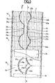
- the impermeable sheet 2 which unwinds in the direction of the arrow F parallel to the longitudinal axis XX, receives along its two longitudinal edges two continuous elastic bands 13.
- the curvilinear portions concaves 13a are glued in the stretched state according to the method which has been described with reference to FIGS. 1 and 2 while the rectilinear portions 13b which connect them to each other are not glued.
- Continuous lines of adhesive 14 deposited on the surface of the impermeable sheet 2 in another step of the process allow the bonding of absorbent cushions 15 of elongated rectangular shape and of a moisture-permeable veil 16.
- the absorbent cushions 15 and the permeable web 16 we proceed to the stage final manufacturing consisting in cutting transversely along the lines 18 the composite strip obtained so as to form the diapers such as that which is illustrated in FIG. 4.
- the rectilinear portions 13b of the crotch elastics 13 are sectioned , the remaining portions resuming their initial length and remaining trapped between the impermeable sheet 2 and the permeable veil 16.
- the absorbent pad has been shown in FIG. 4 as having a rectangular shape, it will be understood that it could also have an hourglass shape. according to the profile of the leg passage openings 19.
- the waterproof sheet 2 moving as before according to arrow F parallel to the longitudinal axis XX receives first of all along its two longitudinal edges a continuous straight elastic 20 glued in the stretched state over its entire surface and intended to form a continuous elastic tightening to the size of the diaper.
- the crotch elastics consist of two elastic strips 21 and 22 glued intermittently on one side and the other respectively of the longitudinal axis X-X.
- the elastic strip 21 comprises curvilinear portions 21a with respect to the future leg passage opening and in the form of a semicircle symmetrical with respect to the transverse lines 18 and cutting the latter perpendicularly. These curvilinear portions 21a bonded over their entire length obtained by the method illustrated in Figures 1 and 2 are interconnected by straight non-bonded portions 21b parallel to the longitudinal axis X-X.
- the elastic bands 22 comprise two curvilinear portions 22a glued over their entire length disposed on each side of the transverse line 18 symmetrically with respect to the latter in the form of an arc of a circle of convex profile with respect to the future leg passage opening.
- the glued portions 22a are connected by a straight non-glued portion 22b intersecting the transverse line 18 and parallel to the axis X - X and a second non-glued rectilinear portion 22c parallel to the axis XX in the immediate vicinity of the latter.
- the non-glued rectilinear portions 21b and 22c are sectioned and removed or simply released so as to allow the laying of absorbent cushions 15 of elongated rectangular shape which are this time arranged transversely, that is to say say perpendicular to the longitudinal axis XX between two transverse lines 18.
- the bonding of the absorbent mattresses 15 is done as previously thanks to the existence of the gluing lines 14.
- the leg passage openings 23 are cut and welded simultaneously around their periphery, the profile of which comprises a first concave arc 23a parallel to the arc of the circle portion 21a of the elastic band 21 and two portions of arc of convex circles 23b parallel respectively to the arcs of circles 22a of the elastic band 22.
- the point formed by the two arcs of a circle 23b which meet substantially tangentially on the line transverse 18 causes at the same time the cutting of the straight non-glued portion 22b of the elastic 22.
- Cutting accompanied by simultaneous welding allows the production of diapers such as diaper 24 which has a weld 25 on its lateral side.
- the diaper obtained therefore looks like a pair of underpants and is put on as such, the elastic of size 20 being made continuous by the two lateral welds 25.
- the method of the invention authorizing the laying in the stretched state of elastic elements of curvilinear shape therefore allows the production of crotch elastics according to the curvilinear profile of the leg passage opening best adapted to the user's anatomy.
Abstract
Description
- La présente invention a pour objet un procédé de fabrication de couches-culottes à jeter présentant des découpes pour le passage des jambes de forme curviligne et munies sur au moins une partie de leur pourtour interne d'éléments élastiques améliorant l'étanchéité au passage des jambes.
- L'invention a également pour objet les couches-culottess obtenues par la mise en oeuvre du procédé de l'invention. Ces couches-culottes peuvent être jetées après usage et peuvent être utilisées pour les enfants en bas âge ou pour les personnes adultes incontinentes. Elles comportent une feuille imperméable externe, un coussin absorbant faisant partie intégrante de l'ensemble et de préférence un voile perméable formant revêtement interne de la couche-culotte.
- Pour améliorer l'étanchéité au passage des jambes des couches-culottes à jeter de ce type, on a déjà préconisé de coller à l'état étiré des bandelettes élastiques rectilignes sur une feuille imperméable destinée à réaliser l'enveloppe extérieure de la couche-culotte.
- A titre d'exemple de produits de ce type on peut citer les couches-culottes décrites dans les brevets américains 3 860 003 et 4 050 462. Les éléments élastiques disposés au voisinage du pourtour des passages des jambes dans de telles couches-culottes qui ont pour but d'améliorer l'étanchéité à cet endroit, ne doivent pas cependant exercer un serrage trop important ou entraîner la formation de replis du matériau et notamment du matériau constituant le coussin absorbant afin de respecter l'anatomie de l'utilisateur qu'il s'agisse d'une personne adulte ou d'un enfant en bas âge.
- On a déjà prévu pour améliorer le profil de couches-culottes équipées de tels élastiques d'entrejambe, une structure particulière du coussin absorbant tel que décrit dans la demande de brevet français 2 438 434.
- La réalisation d'ouvertures ou de découpes d'entrejambe de profil curviligne ne permettait pas jusqu'à présent de fabriquer en continu de manière industrielle et à grande cadence des couche-culottes de ce type présentant des élastiques sur leur pourtour compte tenu de la forme incurvée du pourtour.
- Des couches-culottes à jeter de ce type présentant un ruban élastique sur le bord du contour curviligne du passage des jambes tel que décrit dans le brevet français 2 063 794 ne peuvent être réalisées que par des moyens se prêtant peu à une fabrication à grande cadence et notamment par couture de fils ou de rubans élastiques.
- La présente invention a pour objet un procédé de fabrication qui permet de réaliser de façon simple et à grande cadence des couches-culottes à jeter de ce type comportant des éléments élastiques bordant le contour curviligne des passages de jambes améliorant ainsi l'étanchéité à cet endroit tout en conservant au passage des jambes une forme proche de l'anatomie du l'utilisateur.
- Le procédé de fabrication en continu suivant l'invention permet la réalisation de couches-culottes à jeter comprenant un coussin absorbant disposé entre une enveloppe extérieure imperméable à l'humidité et un voile intérieur perméable, l'ensemble comportant des découpes de profil curviligne pour permettre le passage de jambes, ces découpes étant munies sur le pourtour interne d'éléments élastiques.
- Suivant l'invention, on dépose par intermittence un matériau adhésif à température élevée en fusion (hot meit) sur la face d'une bandelette élastique se déplaçant à l'état tendu et destinée à entrer en contact avec une feuille souple continue
d'un matériau thermosoudable imperméable à l'humidité. On déplace ensuite périodiquement dans une direction transversale au déplacement de ladite feuille imperméable, le point de contact entre la bandelette élastique encollée et la feuille imperméable en mouvement. On obtient de cette manière un élastique d'entrejambe de forme incurvée, collé à l'état tendu le long d'au moins une portion courbe de chaque découpe de passage de jambes. On fait de préférence passer la feuille imperméable sur la périphérie d'un tambour rotatif maintenu à une température relativement basse par rapport à la température de l'adhésif en fusion. De cette manière le matériau 'adhésif déposé à chaud sur la bandelette élastique avant le contact avec la feuille imperméable, subit un refroidissement brutal dès son contact avec ladite feuille imperméable ce qui entraîne un collage immédiat autorisant la réalisation d'un élastique curviligne collé à l'état étiré. - Le choix de la température du tambour rotatif peut aisément être opéré par le technicien en tenant compte des paramètres que constituent la masse dudit tambour, la masse de l'adhésif par unité de longueur de la bandelette élastique, la température de l'adhésif immédiatement avant le contact, la nature de l'adhésif et la courbure désirée de l'élastique d'entrejambe.
- Il convient à cet égard que la différence de température entre l'adhésif déposé et la surface extérieure du tambour rotatif soit suffisante pour entraîner un effet de collage immédiat apte à résister aux efforts transversaux auxquels la bandelette est soumise étant donné le déplacement du point de contact. Dans la pratique, on constate qu'une différence de température d'au moins 20°C est nécessaire et de préférence de 70°C à 130°C.
- Le point de contact entre la bandelette élastique et la feuille imperméable souple est de préférence maintenu fixe par intermittence de façon à-définir des portions rectilignes non collées de bandelette élastique séparant les portions curvilignes collées.
- Le déplacement en direction transversale du point de contact initial entre la bandelette élastique et la feuille imperméable souple peut se faire par tout moyen approprié. Dans un mode de réalisation préféré, on fait passer la bandelette élastique étirée sur un moyen de guidage tel qu'une glissière éventuellement incurvée ou une poulie à gorge montée à proximité immédiate de la périphérie du tambour rotatif, sur un chariot susceptible de se déplacer parallèlement à l'axe du tambour selon un mouvement alternatif de translation. Le moyen de guidage peut comporter des moyens de maintien de la bandelette tels que rebords ou orifices d'aspiration afin d'éviter que la bandelette élastique ne s'échappe du moyen de guidage lors de son mouvement. Ce mouvement peut être commandé par exemple par un dispositif de cames et indexé sur la rotation du tambour de façon que les portions curvilignes des bandelettes élastiques soient réalisées aux endroits appropriés sur la feuille imperméable.
- Le procédé de l'invention peut être appliqué à la réalisation de couches-culottes obtenues par découpe transversale de la feuille imperméable continue. Dans ce cas, les coussins absorbants de forme allongée sont disposés selon l'axe longitudinal de la feuille imperméable et les découpes sont pratiquées sur les bords longitudinaux de la bande composite formée par la feuille imperméable, le coussin absorbant le voile intérieur perméable.
- Le procédé de l'invention peut également être appliqué à la réalisation de couches-culottes comportant un lien, de préférence élastique et continu, disposé à la taille. Dans ce cas, les coussins absorbants de forme allongée sont disposés perpendiculairemnt à l'axe longitudinal de la feuille imperméable et les découpes de passage des jambes sont pratiquées sous la forme d'ouvertures alignées selon l'axe longitudinal et symétriques par rapport à une direction transversale. Les couches-culottes sont alors obtenues par pliage ultérieur selon l'axe longitudinal de la bande composite suivi d'une découpe accompagnée d'une soudure simultanée selon l'axe transversal de symétrie des ouvertures.
- La présente invention a également pour objet la couche culotte à jeter obtenue selon le procédé de l'invention.
- Une telle couche-culotte à jeter comprend un coussin absorbant disposé entre une enveloppe extérieure imperméable à l'humidité et un voile intérieur perméable, l'ensemble comportant des découpes de profil curviligne pour permettre le passage des jambes, munies sur leur pourtour interne d'éléments élastiques. Selon l'invention, la couche-culotte fabriquée selon le procédé de l'invention comporte des élastiques d'entrejambe curvilignes collés le long d'au moins une portion courbe de chaque découpe de passage de jambes.
- La présente invention sera mieux comprise à l'étude de la description de quelques modes de réalisation pris à titre d'exemples nullement limitatifs et illustrés par les dessins annexés sur lesquels :
- La figure 1 est une vue schématique de côté des principaux éléments d'une installation permettant la mise en oeuvre du procédé de l'invention.
- La figure 2 est une vue de dessus des éléments de la figure 1.
- La figure 3 est une vue partielle d'une bande composite illustrant diverses étapes de fabrication d'une couche-culotte selon l'invention.
- La figure 4 est une vue en élévation d'une couche-culotte fabriquée à partir de la bande composite de la figure 3.
- La figure 5 est une bande composite illustrant la fabrication selon une variante de l'invention.
- Et la figure 6 montre le stade final de fabrication dans la variante de la figure 5.
- Telle quelle est représentée de manière très schématique sur les figures 1 et 2, l'installation permettant la mise en oeuvre du procédé de l'invention comprend un tambour rotatif 1 sur lequel vient s'enrouler une feuille souple continue 2 d'un matériau thermo-soudable imperméable à l'humidité tel que du polyéthylène. Le tambour 1 est entraîné en rotation dans le sens de la flèche 3 de sorte que la feuille 2 épouse sur environ la moitié de sa périphérie le tambour rotatif 1. Le tambour 1 est maintenu à une température relativement basse de l'ordre de 20°C. Le maintien de cette température peut être obtenu par un refroidissement artificiel forcé à l'intérieur du tambour ou simplement grâce à l'utilisation d'un tambour de masse suffisante.
- Deux bandelettes élastiques 4 de faible largeur réalisées par exemple en latex sont stockées dans des conteneurs 5. Les bandelettes élastiques 4 passent après extraction des conteneurs 5 sur un galet de guidage 5a puis entre deux rouleaux tendeurs 6 entraînés en rotation de façon que la vitesse de déplacement linéaire de la bandelette élastique 4 à la sortie des rouleaux tendeurs 6 soit inférieure à la vitesse périphérique de la feuille imperméable 2 sur le tambour rotatif 1.
- En règlant la différence de viltesse de manière convenable, on obtient l'élongation désirée de la bandelette élastique 4.
- Un matériau adhésif à haute température par exemple de l'ordre de 100°C à 150°C, rendu liquide par fusion (hot melt) est délivré de manière intermittente par la buse 7 sous forme d'une ligne fine sur la surface de la bandelette élastique 4 destinée à entrer en contact avec la feuille imperméable 2. Une valve non représentée sur la figure permet d'arrêter de manière automatique pendant des périodes de temps déterminées l'alimentation en matériau adhésif. La bandelette élastique 4 éventuellement revêtue d'une ligne de matériau adhésif passe ensuite à l'intérieur d'un organe de guidage 8 fixe puis sur une poulie à gorge 9 montée sur un chariot mobile 10 pouvant coulisser sur une glissière 11 sous l'action d'organes de commande non représentés sur les figures qui peuvent par exemple comporter des cames ou des organes analogues. Après son passage sur la poulie à gorge 9, la bandelette élastique 4 vient en contact avec la feuille imperméable 2 à la périphérie du tambour rotatif 3, le point de contact étant référencé 12 sur les figures. La poulie à gorge 9 est disposée à proximité immédiate de la périphérie du tambour rotatif 3. Dans l'exemple illustré le point de contact 12 se trouve légèrement en aval de la moitié du parcours périphérique de la feuille imperméable 2 sur le tambour rotatif. On pourrait également disposer le point de contact plus en amont du trajet de la feuille 2 de façon à augmenter la durée de refroidissement de l'adhésif en contact avec le tambour 3. La bandelette élastique 4 se dirige depuis la poulie à gorge 9 jusqu'au contact avec la feuille imperméable 2 se trouvant à la périphérie du tambour rotatif 3 selon une direction tangente par rapport au profil du tambour rotatif 3.
- Dans ces conditions et compte tenu de l'écart de température entre le tambour et l'adhésif, le matériau adhésif en fusion se trouvant à la surface de la bandelette élastique 4 se fige aussitôt après le contact entrainant un collage immédiat de sorte que le déplacement en direction transversale des chariots 10 et des points de contact 12, permet le collage de la bandelette élastique selon un profil curviligne 4a comme on peut le voir sur la figure 2. L'écart de température, compte tenu de la masse respective de l'adhésif en fine ligne d'encollage et du tambour rotatif est suffisant pour que l'adhésif se fige dès son contact et résiste à l'effort transversal dû à la pose de la bandelette selon un trajet incurvé.
- Sur la figure 2, on a représenté également en tirets la position occupée par les chariots 10 pour la pose des portions rectiligines des bandelettes élastiques. On remarquera sur la figure 2 que l'angle formé par la bandelette élastique à la sortie de l'organe de guidage 8 a été exagéré pour la clarté du dessin. Dans la pratique on fait en sorte que cet angle maximal ne risque pas d'entraîner l'extraction de la bandelette 4 des poulies à gorge 9. Dans une variante les poulies rotatives 9 peuvent être remplacées par des glissières ou autres moyens de guidage et de maintien de la bandelette élastique en déplacement.
- Dans le mode de réalisation illustré sur la figure 3, la feuille imperméable 2, qui se déroule dans le sens de la flèche F parallèlement à l'axe longitudinal X-X, reçoit le long de ses deux bords longitudinaux deux élastiques continus 13. Les portions curvilignes concaves 13a sont encollées à l'état étiré selon le procédé qui a été décrit en référence aux figures 1 et 2 tandis que les portions rectilignes 13b qui les relient entre elles ne sont pas encollées. Des lignes continues d'adhésif 14 déposées sur la surface de la feuille imperméable 2 dans une autre étape du procédé permettent le collage de coussins absorbants 15 de forme allongée rectangulaire et d'un voile perméable à l'humidité 16.
- Après la pose de dispositifs de rubans adhésifs 17 sur les bords longitudinaux de la feuille 2 et découpe incurvée et soudure simultanée pratiquées sur les bords longitudinaux de la bande composite formée par la feuille 2, les coussins absorbants 15 et.le voile perméable 16, on procède au stade final de fabrication consistant à découper transversalement selon les lignes 18 la bande composite obtenue de façon à former les couches-culottes telles queicelle qui est illustrée sur la figure 4. Lors de la découpe, les portions rectilignes 13b des élastiques d'entrejambe 13 sont sectionnées, les portions subsistantes reprenant leur longueur initiale et restant emprisonnées entre la feuille imperméable 2 et le voile perméable 16.
- - On obtient finalement comme on peut le voir sur la figure 4, une couche-culotte dans laquelle le passage des jambes 19 présente un profil incurvé concave s'adaptant parfaitement à l'anatomie de l'utilisateur, le profil 19 étant bordé intérieurement d'un élastique curviligne 13a posé à l'état étiré et assurant une étanchéité convenable à cet endroit.
- Bien que le coussin absorbant ait été représenté sur la figure 4 comme présentant une forme rectangulaire on comprendra qu'il pourrait également présenter une forme de sablier
suivant le profil des ouvertures de passage de jambes 19. - Dans le mode de réalisation illustré dans les figures 5 - et 6 où les éléments identiques portent les mêmes références, la feuille imperméable 2 se déplaçant comme précédemment selon la flèche F parallèlement à l'axe longitudinal X-X reçoit tout d'abord tout le long de ses deux bords longitudinaux un élastique continu 20 rectiligne encollé à l'état étiré sur toute sa surface et destiné à former un élastique continu de serrage à la taille de la couche-culotte. Les élastiques d'entrejambe sont constitués par deux bandelettes élastiques 21 et 22 encollées de manière intermittente respectivement d'un côté et de l'autre de l'axe longitudinal X-X. La bandelette élastique 21 comporte des portions curvilignes 21a par rapport à la future ouverture de passage de jambe et en forme de demi- cercle symétriques par rapport aux lignes transversales 18 et coupant ces dernières perpendiculairement. Ces portions curvilignes 21a encollées sur toute leur longueur obtenues par le procédé illustré sur les figures 1 et 2 sont reliées entre elles par des portions rectilignes non encollées 21b parallèle à l'axe longitudinal X-X.
- Les élastiques 22 comportent deux portions curvilignes 22a encollées sur toute leur longueur disposées de chaque côté de la ligne transversale 18 symétriquement par rapport à cette dernière en forme d'arc de cercle de profil convexe par rapport à la future ouverture de passage de jambe. Les portions encollées 22a sont reliées par une portion rectiligne 22b non encollée coupant la ligne transversale 18 et parallèle à l'axe X-X et une deuxième portion rectiligne non encollée 22c parallèle à l'axe X-X au voisinage immédiat de ce dernier.
- Lors d'une opération ultérieure, les portions rectilignes non encollées 21b et 22c sont sectionnées et retirées ou simplement relachées de façon à permettre la pose des coussins absorbants 15 de forme allongée rectangulaire qui sont cette fois disposés de manière transversale c'est-à-dire perpendiculairement à l'axe longitudinal X-X entre deux lignes transversales 18. Le collage des matelas absorbants 15 se fait comme précédemment grâce à l'existence des lignes d'encollage 14.
- Après la pose et-le collage du voile perméable 16, on procède au découpage et au soudage simultanés sur leur pourtour des ouvertures de passage de jambe 23 dont le profil comporte un premier arc de cercle 23a concave parallèle à l'arc de cercle de la portion 21a de l'élastique 21 et deux portions d'arc de cercles convexes 23b parallèles respecti- vément aux arcs de cercles 22a de l'élastique 22. La pointe formée par les deux arcs de cercle 23b qui se rejoignent sensiblement tangentiellement sur la ligne transversale 18 entraine en même temps le découpage de la portion rectiligne non encollée 22b de l'élastique 22.
- La fabrication se termine par un pliage autour de l'axe longitudinal X-X de façon à obtenir le produit continu représenté sur la partie gauche de la figure 6.
- Une découpe accompagnée d'une soudure simultanée permet la réalisation des couches-culottes telle que la couche-culotte 24 qui comporte une soudure 25 sur son côté latéral. La couche-culotte obtenue s'apparente donc à un slip et s'enfile comme tel, l'élastique de taille 20 étant rendu continu par les deux soudures latérales 25.
- Dans tous les cas, le procédé de l'invention autorisant la pose à l'état tendu d'éléments élastiques de forme curviligne permet donc la réalisation d'élastiques d'entrejambe suivant le profil curviligne de l'ouverture de passage de jambe la mieux adaptée à l'anatomie de l'utilisateur.
Claims (9)
Priority Applications (1)
| Application Number | Priority Date | Filing Date | Title |
|---|---|---|---|
| AT81107223T ATE12572T1 (de) | 1980-09-15 | 1981-09-14 | Verfahren zur herstellung von wegwerfwindeln und so durch die durchfuehrung dieses verfahrens hergestellte windeln. |
Applications Claiming Priority (2)
| Application Number | Priority Date | Filing Date | Title |
|---|---|---|---|
| FR8019862A FR2490079A1 (fr) | 1980-09-15 | 1980-09-15 | Procede de fabrication de couches-culottes a jeter et couches-culottes obtenues par la mise en oeuvre de ce procede |
| FR8019862 | 1980-09-15 |
Publications (2)
| Publication Number | Publication Date |
|---|---|
| EP0048010A1 true EP0048010A1 (fr) | 1982-03-24 |
| EP0048010B1 EP0048010B1 (fr) | 1985-04-10 |
Family
ID=9245935
Family Applications (1)
| Application Number | Title | Priority Date | Filing Date |
|---|---|---|---|
| EP81107223A Expired EP0048010B1 (fr) | 1980-09-15 | 1981-09-14 | Procédé de fabrication de couches-culottes à jeter et couches-culottes obtenues par la mise en oeuvre de ce procédé |
Country Status (7)
| Country | Link |
|---|---|
| US (1) | US4801345A (fr) |
| EP (1) | EP0048010B1 (fr) |
| JP (1) | JPS57117602A (fr) |
| AT (1) | ATE12572T1 (fr) |
| DE (1) | DE3169849D1 (fr) |
| ES (1) | ES8206162A1 (fr) |
| FR (1) | FR2490079A1 (fr) |
Cited By (16)
| Publication number | Priority date | Publication date | Assignee | Title |
|---|---|---|---|---|
| GB2123272A (en) * | 1982-06-21 | 1984-02-01 | Kimberly Clark Co | Apparatus and method for producing elasticized disposable garments |
| FR2534566A1 (fr) * | 1982-10-14 | 1984-04-20 | Winkler Duennebier Kg Masch | Procede et dispositif pour la mise en place synchronisee de bandes elastiques sur une feuille de matiere non elastique deplacee de facon continue |
| FR2539274A1 (fr) * | 1983-01-19 | 1984-07-20 | Boussac Saint Freres Bsf | Procede de fabrication de couches-culottes a jeter et couches-culottes obtenues |
| FR2542979A1 (fr) * | 1983-03-25 | 1984-09-28 | Boussac Saint Freres Bsf | Procede de fabrication en continu de couches-culottes a jeter et couches-culottes obtenues |
| WO1986002530A1 (fr) * | 1983-05-24 | 1986-05-09 | DUNI BILA^o AB | Couche d'incontinence et procede de fixation de bandes elastiques sur celle-ci |
| US4662382A (en) * | 1985-01-16 | 1987-05-05 | Intermedics, Inc. | Pacemaker lead with enhanced sensitivity |
| EP0286635A1 (fr) * | 1985-10-28 | 1988-10-19 | Kimberly Clark Co | Procede et appareil pour appliquer a un substrat un materiau elastique de forme anatomique. |
| WO1989009550A1 (fr) * | 1988-04-11 | 1989-10-19 | Mölnlycke AB | Appareil et procede de pose de fils elastiques sur un materiau en bande |
| EP0351389A1 (fr) * | 1988-07-12 | 1990-01-17 | Mölnlycke AB | Procédé et dispositif pour disposer au moins un fil, une bande ou quelque chose de similaire, sur un modèle préfixé, sur une bande |
| EP0405575A1 (fr) * | 1989-06-29 | 1991-01-02 | Uni-Charm Corporation | Procédé de fabrication de slips à jeter |
| EP0417766A1 (fr) * | 1989-09-13 | 1991-03-20 | Uni-Charm Corporation | Procédé de fabrication de vêtements jetables |
| EP0475419A1 (fr) * | 1990-09-13 | 1992-03-18 | Uni-Charm Corporation | Vêtements jetable, et procédé pour mettre des éléments élastiques autour des ouvertures de jambes |
| FR2668364A1 (fr) * | 1990-10-26 | 1992-04-30 | Peaudouce | Couche-culotte a elements elastiques d'entrejambes et de ceinture, et procede et installation pour la fabrication en continu de telles couches-culottes. |
| WO1996023477A2 (fr) * | 1995-01-31 | 1996-08-08 | Kimberly-Clark Worldwide, Inc. | Sous-vetement jetable et equipement et procedes de fabrication correspondants |
| US5779689A (en) * | 1990-10-26 | 1998-07-14 | Peaudouce | Diapers with elasticized crotch and end regions and a process and apparatus for the continuous manufacture thereof |
| US8622984B2 (en) | 1995-01-31 | 2014-01-07 | Kimberly-Clark Worldwide, Inc. | Disposable undergarment and related manufacturing equipment and processes |
Families Citing this family (138)
| Publication number | Priority date | Publication date | Assignee | Title |
|---|---|---|---|---|
| US4917746A (en) * | 1982-06-21 | 1990-04-17 | Kons Hugo L | Apparatus and method for contouring elastic ribbon on disposable garments |
| JPH0611277B2 (ja) * | 1985-03-19 | 1994-02-16 | ト−ヨ−衛材株式会社 | 使い捨ておしめの製造方法 |
| JPH0653962B2 (ja) * | 1985-07-19 | 1994-07-20 | ユニ・チヤ−ム株式会社 | 使い捨て吸収性パンツおよびその製法 |
| JPH0653963B2 (ja) * | 1985-07-19 | 1994-07-20 | ユニ・チヤ−ム株式会社 | 使い捨て吸収性パンツおよびその製法 |
| US4661102A (en) * | 1985-12-03 | 1987-04-28 | The Procter & Gamble Company | Disposable diaper featuring crotch tensioning means for improved leakage resistance and fit |
| JP2609252B2 (ja) * | 1987-08-18 | 1997-05-14 | ユニ・チャーム 株式会社 | 移動ウエブへの弾性バンド貼着装置 |
| JPH01141711U (fr) * | 1988-03-14 | 1989-09-28 | ||
| JP2583104B2 (ja) * | 1988-05-18 | 1997-02-19 | 株式会社 瑞光 | ブリ−フ形おむつの製造方法 |
| JPH01298203A (ja) * | 1988-05-24 | 1989-12-01 | Zuikou:Kk | ブリーフ形おむつカバーとその製造方法 |
| US4915767A (en) * | 1988-11-17 | 1990-04-10 | Kimberly-Clark Corporation | Apparatus for applying an elastic in a curved pattern to a moving web |
| JP2880189B2 (ja) * | 1989-08-25 | 1999-04-05 | ユニ・チャーム 株式会社 | パンツ型使い捨て着用物品 |
| US5545275A (en) * | 1989-11-28 | 1996-08-13 | Herrin; Robert M. | Method for welding seams in disposable garments |
| US6309487B1 (en) | 1989-11-28 | 2001-10-30 | Robert M. Herrin | Disposable garments and method and apparatus for making |
| JPH0759243B2 (ja) * | 1989-12-18 | 1995-06-28 | ユニ・チャーム株式会社 | 使い捨て着用物品 |
| JP2664501B2 (ja) * | 1989-12-22 | 1997-10-15 | ユニ・チャーム株式会社 | 使い捨て着用物品 |
| CA2034984A1 (fr) * | 1990-09-21 | 1992-03-22 | Paul T. Van Gompel | Article absorbant a couche labyrinthe |
| JP2603654Y2 (ja) * | 1992-08-26 | 2000-03-15 | トーヨー衛材株式会社 | パンツ型使い捨ておむつ |
| US5275676A (en) * | 1992-09-18 | 1994-01-04 | Kimberly-Clark Corporation | Method and apparatus for applying a curved elastic to a moving web |
| US6319347B1 (en) | 1994-01-25 | 2001-11-20 | Kimberly-Clark Worldwide, Inc. | Method for placing discrete parts transversely onto a moving web |
| US5500075A (en) * | 1994-04-26 | 1996-03-19 | Paragon Trade Brands, Inc. | Leg elastic applicator which maintains the spacing between the elastics substantially constant |
| SE503112C2 (sv) * | 1994-05-16 | 1996-03-25 | Moelnlycke Ab | För engångsanvändning avsett vätskeabsorberande alster, förfarande och anordning för dess framställning |
| US5525175A (en) * | 1994-05-27 | 1996-06-11 | Kimberly-Clark Corporation | Apparatus and method for applying a curved elastic to a moving web |
| US6077254A (en) * | 1994-07-12 | 2000-06-20 | Paragon Trade Brands, Inc. | Absorbent garment with containment pocket |
| JPH07289585A (ja) * | 1994-12-19 | 1995-11-07 | Uni Charm Corp | 使い捨て着用物品 |
| JPH07289588A (ja) * | 1994-12-19 | 1995-11-07 | Uni Charm Corp | 使い捨て着用物品 |
| JPH07289587A (ja) * | 1994-12-19 | 1995-11-07 | Uni Charm Corp | 使い捨て着用物品 |
| JPH07284509A (ja) * | 1994-12-19 | 1995-10-31 | Uni Charm Corp | 使い捨て着用物品に脚回り用の弾性部材を配置する方法 |
| JPH07289586A (ja) * | 1994-12-19 | 1995-11-07 | Uni Charm Corp | 使い捨て着用物品 |
| JP2781528B2 (ja) * | 1995-01-30 | 1998-07-30 | ユニ・チャーム株式会社 | 使い捨てブリーフ型パンツ |
| JP2532824B2 (ja) * | 1995-01-30 | 1996-09-11 | ユニ・チャーム株式会社 | 使い捨てブリ―フの製造装置 |
| US5659229A (en) * | 1995-01-31 | 1997-08-19 | Kimberly-Clark Worldwide, Inc. | Controlling web tension by actively controlling velocity of dancer roll |
| SE505392C2 (sv) | 1995-11-16 | 1997-08-18 | Moelnlycke Ab | Vätskeabsorberande artikel försedd med krökt elastik för bildande av läckagespärr |
| US5879500A (en) * | 1996-06-21 | 1999-03-09 | Herrin; Robert M. | Disposable undergarment forming apparatus and method of forming same |
| US6116317A (en) | 1996-06-21 | 2000-09-12 | Tharpe, Jr.; John M. | Apparatus having a core orientor and methods of orienting portions of a disposable undergarment |
| US6314333B1 (en) | 1998-07-03 | 2001-11-06 | Kimberly-Clark Worldwide, Inc. | Method and apparatus for controlling web tension by actively controlling velocity and acceleration of a dancer roll |
| US6856850B2 (en) | 1998-07-03 | 2005-02-15 | Kimberly Clark Worldwide, Inc. | Controlling web tension, and accumulating lengths of web, using a festoon |
| US6473669B2 (en) | 1998-07-03 | 2002-10-29 | Kimberly-Clark Worldwide, Inc. | Controlling web tension, and accumulating lengths of web, by actively controlling velocity and acceleration of a festoon |
| US6197138B1 (en) | 1998-12-29 | 2001-03-06 | Kimberly-Clark Worldwide, Inc. | Machine and process for placing and bonding elastic members in a relaxed state to a moving substrate web |
| SE513314C2 (sv) | 1998-12-29 | 2000-08-21 | Sca Hygiene Prod Ab | Förfarande och anordning för att anbringa elastik på en löpande materialbana |
| US6387471B1 (en) | 1999-03-31 | 2002-05-14 | Kimberly-Clark Worldwide, Inc. | Creep resistant composite elastic material with improved aesthetics, dimensional stability and inherent latency and method of producing same |
| US6547915B2 (en) | 1999-04-15 | 2003-04-15 | Kimberly-Clark Worldwide, Inc. | Creep resistant composite elastic material with improved aesthetics, dimensional stability and inherent latency and method of producing same |
| US6833179B2 (en) | 2000-05-15 | 2004-12-21 | Kimberly-Clark Worldwide, Inc. | Targeted elastic laminate having zones of different basis weights |
| US20050106971A1 (en) * | 2000-05-15 | 2005-05-19 | Thomas Oomman P. | Elastomeric laminate with film and strands suitable for a nonwoven garment |
| US8182457B2 (en) * | 2000-05-15 | 2012-05-22 | Kimberly-Clark Worldwide, Inc. | Garment having an apparent elastic band |
| US6969441B2 (en) * | 2000-05-15 | 2005-11-29 | Kimberly-Clark Worldwide, Inc. | Method and apparatus for producing laminated articles |
| DE60114289T2 (de) | 2000-05-15 | 2006-04-20 | Kao Corp. | Absorbierender Artikel |
| US6503238B1 (en) | 2000-06-16 | 2003-01-07 | Sca Hygiene Products Ab | Disposable liquid absorbent article with elasticizing members |
| US6589149B1 (en) * | 2000-08-15 | 2003-07-08 | Kimberly-Clark Worldwide, Inc. | Method and apparatus for applying a curved component to a moving web |
| US6537403B1 (en) | 2001-12-18 | 2003-03-25 | Kimberly-Clark Worldwide, Inc. | Nip adjustment for a rigid ultrasonic bonder or processor |
| US6613171B2 (en) | 2001-12-18 | 2003-09-02 | Kimberly-Clark Worldwide, Inc. | Rotary ultrasonic bonder or processor capable of fixed gap operation |
| US6676003B2 (en) | 2001-12-18 | 2004-01-13 | Kimberly-Clark Worldwide, Inc. | Rigid isolation of rotary ultrasonic horn |
| US6547903B1 (en) | 2001-12-18 | 2003-04-15 | Kimberly-Clark Worldwide, Inc. | Rotary ultrasonic bonder or processor capable of high speed intermittent processing |
| US6620270B2 (en) | 2001-12-18 | 2003-09-16 | Kimberly-Clark Worldwide, Inc. | Control of processing force and process gap in rigid rotary ultrasonic systems |
| US20030173024A1 (en) * | 2002-03-15 | 2003-09-18 | Nordson Corporation | Method of securing elastic strands to flat substrates and products produced by the method |
| US20050013975A1 (en) * | 2003-07-14 | 2005-01-20 | Nordson Corporation | Method of securing elastic strands to flat substrates and products produced by the method |
| US6911232B2 (en) * | 2002-04-12 | 2005-06-28 | Nordson Corporation | Module, nozzle and method for dispensing controlled patterns of liquid material |
| US7316842B2 (en) * | 2002-07-02 | 2008-01-08 | Kimberly-Clark Worldwide, Inc. | High-viscosity elastomeric adhesive composition |
| US7335273B2 (en) | 2002-12-26 | 2008-02-26 | Kimberly-Clark Worldwide, Inc. | Method of making strand-reinforced elastomeric composites |
| US7316840B2 (en) * | 2002-07-02 | 2008-01-08 | Kimberly-Clark Worldwide, Inc. | Strand-reinforced composite material |
| US20040068246A1 (en) * | 2002-10-02 | 2004-04-08 | Kimberly-Clark Worldwide, Inc. | Disposable garments with improved elastic filament placement control and methods of producing same |
| US7578882B2 (en) * | 2003-01-22 | 2009-08-25 | Nordson Corporation | Module, nozzle and method for dispensing controlled patterns of liquid material |
| US20050010188A1 (en) * | 2003-07-10 | 2005-01-13 | Glaug Frank S. | Efficiently manufacturable absorbent disposable undergarment and method of manufacturing absorbent disposable article |
| US7179343B2 (en) * | 2003-12-19 | 2007-02-20 | Kimberly-Clark Worldwide, Inc. | Method for bonding surfaces on a web |
| US20050142339A1 (en) * | 2003-12-30 | 2005-06-30 | Price Cindy L. | Reinforced elastic laminate |
| US6964238B2 (en) * | 2003-12-31 | 2005-11-15 | Kimberly-Clark Worldwide, Inc. | Process for making a garment having hanging legs |
| US7601657B2 (en) * | 2003-12-31 | 2009-10-13 | Kimberly-Clark Worldwide, Inc. | Single sided stretch bonded laminates, and methods of making same |
| US7303708B2 (en) * | 2004-04-19 | 2007-12-04 | Curt G. Joa, Inc. | Super absorbent distribution system design for homogeneous distribution throughout an absorbent core |
| US8417374B2 (en) * | 2004-04-19 | 2013-04-09 | Curt G. Joa, Inc. | Method and apparatus for changing speed or direction of an article |
| US7703599B2 (en) * | 2004-04-19 | 2010-04-27 | Curt G. Joa, Inc. | Method and apparatus for reversing direction of an article |
| US7374627B2 (en) * | 2004-04-19 | 2008-05-20 | Curt G. Joa, Inc. | Method of producing an ultrasonically bonded lap seam |
| US7640962B2 (en) * | 2004-04-20 | 2010-01-05 | Curt G. Joa, Inc. | Multiple tape application method and apparatus |
| US7708849B2 (en) * | 2004-04-20 | 2010-05-04 | Curt G. Joa, Inc. | Apparatus and method for cutting elastic strands between layers of carrier webs |
| US20050230449A1 (en) * | 2004-04-20 | 2005-10-20 | Curt G. Joa, Inc. | Apparatus and method of increasing web storage in a dancer |
| US20050230037A1 (en) | 2004-04-20 | 2005-10-20 | Curt G. Joa, Inc. | Staggered cutting knife |
| US7638014B2 (en) | 2004-05-21 | 2009-12-29 | Curt G. Joa, Inc. | Method of producing a pants-type diaper |
| EP1774936B1 (fr) * | 2004-07-30 | 2011-06-29 | Kao Corporation | Couche jetable de type calecon |
| JP4493435B2 (ja) * | 2004-07-30 | 2010-06-30 | 花王株式会社 | パンツ型使い捨ておむつ |
| US7811403B2 (en) * | 2005-03-09 | 2010-10-12 | Curt G. Joa, Inc. | Transverse tab application method and apparatus |
| US7452436B2 (en) * | 2005-03-09 | 2008-11-18 | Curt G. Joa, Inc. | Transverse tape application method and apparatus |
| US8007484B2 (en) * | 2005-04-01 | 2011-08-30 | Curt G. Joa, Inc. | Pants type product and method of making the same |
| US20060258249A1 (en) * | 2005-05-11 | 2006-11-16 | Fairbanks Jason S | Elastic laminates and process for producing same |
| US7618513B2 (en) * | 2005-05-31 | 2009-11-17 | Curt G. Joa, Inc. | Web stabilization on a slip and cut applicator |
| US7533709B2 (en) * | 2005-05-31 | 2009-05-19 | Curt G. Joa, Inc. | High speed vacuum porting |
| US20070048497A1 (en) * | 2005-08-31 | 2007-03-01 | Peiguang Zhou | Single-faced neck bonded laminates and methods of making same |
| US20070073262A1 (en) * | 2005-09-28 | 2007-03-29 | Kimberly Babusik | Absorbent article and method of making same |
| US7398870B2 (en) * | 2005-10-05 | 2008-07-15 | Curt G. Joa, Inc | Article transfer and placement apparatus |
| US20070141937A1 (en) * | 2005-12-15 | 2007-06-21 | Joerg Hendrix | Filament-meltblown composite materials, and methods of making same |
| US7770712B2 (en) * | 2006-02-17 | 2010-08-10 | Curt G. Joa, Inc. | Article transfer and placement apparatus with active puck |
| US20070250032A1 (en) * | 2006-03-08 | 2007-10-25 | Curt G. Joa, Inc. | Refastenable tab for disposable pant and methods for making same |
| US8172977B2 (en) | 2009-04-06 | 2012-05-08 | Curt G. Joa, Inc. | Methods and apparatus for application of nested zero waste ear to traveling web |
| US10456302B2 (en) | 2006-05-18 | 2019-10-29 | Curt G. Joa, Inc. | Methods and apparatus for application of nested zero waste ear to traveling web |
| US8016972B2 (en) | 2007-05-09 | 2011-09-13 | Curt G. Joa, Inc. | Methods and apparatus for application of nested zero waste ear to traveling web |
| US9433538B2 (en) | 2006-05-18 | 2016-09-06 | Curt G. Joa, Inc. | Methods and apparatus for application of nested zero waste ear to traveling web and formation of articles using a dual cut slip unit |
| US9622918B2 (en) | 2006-05-18 | 2017-04-18 | Curt G. Joe, Inc. | Methods and apparatus for application of nested zero waste ear to traveling web |
| US7780052B2 (en) * | 2006-05-18 | 2010-08-24 | Curt G. Joa, Inc. | Trim removal system |
| EP1895038A3 (fr) * | 2006-08-28 | 2008-03-12 | Curt G. Joa, Inc. | Appareil et procédé pour le mouillage d'une toile continue |
| US7731815B2 (en) * | 2006-11-06 | 2010-06-08 | The Procter & Gamble Company | Method and apparatus for nonlinear laying of material |
| US20080169373A1 (en) * | 2007-01-12 | 2008-07-17 | Curt G. Joa, Inc. | Apparatus and methods for minimizing waste during web splicing |
| US9944487B2 (en) | 2007-02-21 | 2018-04-17 | Curt G. Joa, Inc. | Single transfer insert placement method and apparatus |
| US9550306B2 (en) | 2007-02-21 | 2017-01-24 | Curt G. Joa, Inc. | Single transfer insert placement and apparatus with cross-direction insert placement control |
| EP2486903B1 (fr) | 2007-02-21 | 2023-08-30 | Curt G. Joa, Inc. | Procédé et appareil de positionnement d'insert de transfert unique |
| US20080287897A1 (en) * | 2007-05-14 | 2008-11-20 | Tyco Healthcare Retail Services Ag | Absorbent article and method of making same |
| US20080287899A1 (en) * | 2007-05-14 | 2008-11-20 | Tyco Healthcare Retail Services Ag | Absorbent article and method of making same |
| US20080287898A1 (en) * | 2007-05-14 | 2008-11-20 | Tyco Healthcare Retail Services Ag | Absorbent article and method of making same |
| US8398793B2 (en) * | 2007-07-20 | 2013-03-19 | Curt G. Joa, Inc. | Apparatus and method for minimizing waste and improving quality and production in web processing operations |
| US9387131B2 (en) | 2007-07-20 | 2016-07-12 | Curt G. Joa, Inc. | Apparatus and method for minimizing waste and improving quality and production in web processing operations by automated threading and re-threading of web materials |
| US8182624B2 (en) | 2008-03-12 | 2012-05-22 | Curt G. Joa, Inc. | Registered stretch laminate and methods for forming a registered stretch laminate |
| US8171972B2 (en) | 2009-01-30 | 2012-05-08 | The Procter & Gamble Company | Strip guide for high-speed continuous application of a strip material to a moving sheet-like substrate material at laterally shifting locations |
| US20100193138A1 (en) * | 2009-01-30 | 2010-08-05 | Joseph Allen Eckstein | System for High-Speed Continuous Application of a Strip Material to a Moving Sheet-Like Substrate Material at Laterally Shifting Locations |
| US20100193135A1 (en) * | 2009-01-30 | 2010-08-05 | Joseph Allen Eckstein | System and Method for High-Speed Continuous Application of a Strip Material to a Moving Sheet-Like Substrate Material at Laterally Shifting Locations |
| US8182627B2 (en) * | 2009-01-30 | 2012-05-22 | The Procter & Gamble Company | Method for high-speed continuous application of a strip material to a substrate along an application path on the substrate |
| US8673098B2 (en) * | 2009-10-28 | 2014-03-18 | Curt G. Joa, Inc. | Method and apparatus for stretching segmented stretchable film and application of the segmented film to a moving web |
| US9089453B2 (en) | 2009-12-30 | 2015-07-28 | Curt G. Joa, Inc. | Method for producing absorbent article with stretch film side panel and application of intermittent discrete components of an absorbent article |
| US8460495B2 (en) * | 2009-12-30 | 2013-06-11 | Curt G. Joa, Inc. | Method for producing absorbent article with stretch film side panel and application of intermittent discrete components of an absorbent article |
| US8663411B2 (en) | 2010-06-07 | 2014-03-04 | Curt G. Joa, Inc. | Apparatus and method for forming a pant-type diaper with refastenable side seams |
| US9603752B2 (en) | 2010-08-05 | 2017-03-28 | Curt G. Joa, Inc. | Apparatus and method for minimizing waste and improving quality and production in web processing operations by automatic cuff defect correction |
| MY195691A (en) | 2010-09-16 | 2023-02-03 | Dsg Technology Holdings Ltd | Article With Elastic Distribution and System and Method for Making Same |
| WO2012053945A1 (fr) * | 2010-10-18 | 2012-04-26 | Sca Hygiene Products Ab | Procédé d'application d'éléments élastiques à un article jetable et article jetable fabriqué selon le procédé |
| US9566193B2 (en) | 2011-02-25 | 2017-02-14 | Curt G. Joa, Inc. | Methods and apparatus for forming disposable products at high speeds with small machine footprint |
| US8656817B2 (en) | 2011-03-09 | 2014-02-25 | Curt G. Joa | Multi-profile die cutting assembly |
| USD684613S1 (en) | 2011-04-14 | 2013-06-18 | Curt G. Joa, Inc. | Sliding guard structure |
| US8820380B2 (en) | 2011-07-21 | 2014-09-02 | Curt G. Joa, Inc. | Differential speed shafted machines and uses therefor, including discontinuous and continuous side by side bonding |
| PL2628472T3 (pl) | 2012-02-20 | 2016-07-29 | Joa Curt G Inc | Sposób tworzenia spojeń między oddzielnymi częściami składowymi produktów jednorazowego użytku |
| US9682392B2 (en) | 2012-04-11 | 2017-06-20 | Nordson Corporation | Method for applying varying amounts or types of adhesive on an elastic strand |
| US9809414B2 (en) | 2012-04-24 | 2017-11-07 | Curt G. Joa, Inc. | Elastic break brake apparatus and method for minimizing broken elastic rethreading |
| EP2866753A1 (fr) | 2012-06-29 | 2015-05-06 | The Procter & Gamble Company | Système et procédé pour l'application continue à grande vitesse d'un matériau de bande sur un matériau de substrat mobile du type feuille |
| US9283683B2 (en) | 2013-07-24 | 2016-03-15 | Curt G. Joa, Inc. | Ventilated vacuum commutation structures |
| USD703712S1 (en) | 2013-08-23 | 2014-04-29 | Curt G. Joa, Inc. | Ventilated vacuum commutation structure |
| USD704237S1 (en) | 2013-08-23 | 2014-05-06 | Curt G. Joa, Inc. | Ventilated vacuum commutation structure |
| USD703248S1 (en) | 2013-08-23 | 2014-04-22 | Curt G. Joa, Inc. | Ventilated vacuum commutation structure |
| USD703247S1 (en) | 2013-08-23 | 2014-04-22 | Curt G. Joa, Inc. | Ventilated vacuum commutation structure |
| USD703711S1 (en) | 2013-08-23 | 2014-04-29 | Curt G. Joa, Inc. | Ventilated vacuum communication structure |
| US9289329B1 (en) | 2013-12-05 | 2016-03-22 | Curt G. Joa, Inc. | Method for producing pant type diapers |
| DE102014203742A1 (de) * | 2014-02-28 | 2015-09-03 | Paul Hartmann Ag | Hygieneartikel und Verfahren zum Herstellen eines Hygieneartikels |
| PL3325387T3 (pl) | 2015-07-24 | 2022-06-20 | Curt G. Joa, Inc. | Urządzenie do komutacji próżniowej oraz sposoby |
| IT201800006021A1 (it) * | 2018-06-08 | 2019-12-08 | Dispositivo di guida per l'applicazione di un filo e procedimento | |
| IT201800006019A1 (it) * | 2018-06-08 | 2019-12-08 | Dispositivo di guida per l'applicazione di un filo e procedimento | |
| US11737930B2 (en) | 2020-02-27 | 2023-08-29 | Curt G. Joa, Inc. | Configurable single transfer insert placement method and apparatus |
Citations (6)
| Publication number | Priority date | Publication date | Assignee | Title |
|---|---|---|---|---|
| FR2063794A5 (fr) | 1969-10-31 | 1971-07-09 | Feron Danielle | |
| FR2082803A5 (fr) * | 1970-03-26 | 1971-12-10 | Consortium General Textile | |
| FR2086605A5 (fr) * | 1970-04-02 | 1971-12-31 | Consortium General Textile | |
| FR2177425A1 (en) * | 1971-10-13 | 1973-11-09 | Elastelle Fontanille | Disposable garments - having elasticated borders |
| DE2649948A1 (de) * | 1975-10-30 | 1977-05-12 | Procter & Gamble | Verfahren und vorrichtung zum anbringen von elastischen baendern an sich bewegenden bahnen |
| EP0023804A1 (fr) * | 1979-07-25 | 1981-02-11 | JOHNSON & JOHNSON BABY PRODUCTS COMPANY | Structure laminée froncée comportant un élément élastique perforé et procédé pour sa fabrication |
Family Cites Families (6)
| Publication number | Priority date | Publication date | Assignee | Title |
|---|---|---|---|---|
| US3150023A (en) * | 1960-12-01 | 1964-09-22 | Magee Carpet Co | Method and apparatus for laminating a layer of plastic and scrim on the backing of carpet |
| FR2112075B1 (fr) * | 1970-09-18 | 1973-12-07 | Elastelle Fontanille Il | |
| US3950207A (en) * | 1972-06-06 | 1976-04-13 | Texsa S.A. | Process for the manufacture of multilayer impermeable strips |
| US4352355A (en) * | 1978-04-03 | 1982-10-05 | Johnson & Johnson Baby Products Company | Diaper with contoured panel and contoured elastic means |
| US4405397A (en) * | 1979-10-16 | 1983-09-20 | Riegel Textile Corporation | Process for manufacturing elastic leg disposable diapers |
| US4293367A (en) * | 1980-05-16 | 1981-10-06 | Johnson & Johnson Baby Products Company | Apparatus for effecting securement of a transversely moved elastic ribbon to a moving web |
-
1980
- 1980-09-15 FR FR8019862A patent/FR2490079A1/fr active Granted
-
1981
- 1981-09-14 EP EP81107223A patent/EP0048010B1/fr not_active Expired
- 1981-09-14 DE DE8181107223T patent/DE3169849D1/de not_active Expired
- 1981-09-14 AT AT81107223T patent/ATE12572T1/de not_active IP Right Cessation
- 1981-09-14 JP JP56144041A patent/JPS57117602A/ja active Pending
- 1981-09-15 ES ES506043A patent/ES8206162A1/es not_active Expired
-
1984
- 1984-05-01 US US06/605,970 patent/US4801345A/en not_active Expired - Lifetime
Patent Citations (6)
| Publication number | Priority date | Publication date | Assignee | Title |
|---|---|---|---|---|
| FR2063794A5 (fr) | 1969-10-31 | 1971-07-09 | Feron Danielle | |
| FR2082803A5 (fr) * | 1970-03-26 | 1971-12-10 | Consortium General Textile | |
| FR2086605A5 (fr) * | 1970-04-02 | 1971-12-31 | Consortium General Textile | |
| FR2177425A1 (en) * | 1971-10-13 | 1973-11-09 | Elastelle Fontanille | Disposable garments - having elasticated borders |
| DE2649948A1 (de) * | 1975-10-30 | 1977-05-12 | Procter & Gamble | Verfahren und vorrichtung zum anbringen von elastischen baendern an sich bewegenden bahnen |
| EP0023804A1 (fr) * | 1979-07-25 | 1981-02-11 | JOHNSON & JOHNSON BABY PRODUCTS COMPANY | Structure laminée froncée comportant un élément élastique perforé et procédé pour sa fabrication |
Cited By (27)
| Publication number | Priority date | Publication date | Assignee | Title |
|---|---|---|---|---|
| GB2123272A (en) * | 1982-06-21 | 1984-02-01 | Kimberly Clark Co | Apparatus and method for producing elasticized disposable garments |
| FR2534566A1 (fr) * | 1982-10-14 | 1984-04-20 | Winkler Duennebier Kg Masch | Procede et dispositif pour la mise en place synchronisee de bandes elastiques sur une feuille de matiere non elastique deplacee de facon continue |
| FR2539274A1 (fr) * | 1983-01-19 | 1984-07-20 | Boussac Saint Freres Bsf | Procede de fabrication de couches-culottes a jeter et couches-culottes obtenues |
| EP0115286A1 (fr) * | 1983-01-19 | 1984-08-08 | BOUSSAC SAINT FRERES B.S.F. Société anonyme dite: | Procédé de fabrication de couches-culottes à jeter et couches-culottes obtenues |
| US4762582A (en) * | 1983-03-25 | 1988-08-09 | Boussac Saint Freres B.S.F. | Continuous process for the manufacture of disposable diapers |
| FR2542979A1 (fr) * | 1983-03-25 | 1984-09-28 | Boussac Saint Freres Bsf | Procede de fabrication en continu de couches-culottes a jeter et couches-culottes obtenues |
| EP0121178A1 (fr) * | 1983-03-25 | 1984-10-10 | BOUSSAC SAINT FRERES B.S.F. Société anonyme dite: | Procédé de fabrication en continu de couches-culottes à jeter et couches-culottes obtenues |
| WO1986002530A1 (fr) * | 1983-05-24 | 1986-05-09 | DUNI BILA^o AB | Couche d'incontinence et procede de fixation de bandes elastiques sur celle-ci |
| US4662382A (en) * | 1985-01-16 | 1987-05-05 | Intermedics, Inc. | Pacemaker lead with enhanced sensitivity |
| EP0286635A1 (fr) * | 1985-10-28 | 1988-10-19 | Kimberly Clark Co | Procede et appareil pour appliquer a un substrat un materiau elastique de forme anatomique. |
| EP0286635A4 (fr) * | 1985-10-28 | 1989-02-16 | Kimberly Clark Co | Procede et appareil pour appliquer a un substrat un materiau elastique de forme anatomique. |
| WO1989009550A1 (fr) * | 1988-04-11 | 1989-10-19 | Mölnlycke AB | Appareil et procede de pose de fils elastiques sur un materiau en bande |
| GR890100205A (en) * | 1988-04-11 | 1990-01-31 | Moelnlycke Ab | Apparatus and method for laying elastic thread on a web of material |
| US5236539A (en) * | 1988-04-11 | 1993-08-17 | Rogberg John A | Apparatus for laying elastic thread on a web of material |
| EP0351389A1 (fr) * | 1988-07-12 | 1990-01-17 | Mölnlycke AB | Procédé et dispositif pour disposer au moins un fil, une bande ou quelque chose de similaire, sur un modèle préfixé, sur une bande |
| US5221390A (en) * | 1988-07-12 | 1993-06-22 | Molnlyke Ab | Method and apparatus for positioning at least one thread, band or the like in a pre-determined pattern on a material web |
| WO1990000514A1 (fr) * | 1988-07-12 | 1990-01-25 | Mölnlycke AB | Procede et appareil pour le positionnement d'au moins un fil, ruban ou analogue suivant une configuration predeterminee, sur une bande de tissu |
| EP0405575A1 (fr) * | 1989-06-29 | 1991-01-02 | Uni-Charm Corporation | Procédé de fabrication de slips à jeter |
| EP0417766A1 (fr) * | 1989-09-13 | 1991-03-20 | Uni-Charm Corporation | Procédé de fabrication de vêtements jetables |
| EP0475419A1 (fr) * | 1990-09-13 | 1992-03-18 | Uni-Charm Corporation | Vêtements jetable, et procédé pour mettre des éléments élastiques autour des ouvertures de jambes |
| US5413654A (en) * | 1990-09-13 | 1995-05-09 | Uni-Charm Corporation | Disposable garments and method for attachment of elastic members around leg-holes thereof |
| FR2668364A1 (fr) * | 1990-10-26 | 1992-04-30 | Peaudouce | Couche-culotte a elements elastiques d'entrejambes et de ceinture, et procede et installation pour la fabrication en continu de telles couches-culottes. |
| WO1992007531A1 (fr) * | 1990-10-26 | 1992-05-14 | Peaudouce | Couche-culotte a elements elastiques, procede et installation pour sa fabrication en continu |
| US5779689A (en) * | 1990-10-26 | 1998-07-14 | Peaudouce | Diapers with elasticized crotch and end regions and a process and apparatus for the continuous manufacture thereof |
| WO1996023477A2 (fr) * | 1995-01-31 | 1996-08-08 | Kimberly-Clark Worldwide, Inc. | Sous-vetement jetable et equipement et procedes de fabrication correspondants |
| WO1996023477A3 (fr) * | 1995-01-31 | 1996-09-26 | Kimberly Clark Co | Sous-vetement jetable et equipement et procedes de fabrication correspondants |
| US8622984B2 (en) | 1995-01-31 | 2014-01-07 | Kimberly-Clark Worldwide, Inc. | Disposable undergarment and related manufacturing equipment and processes |
Also Published As
| Publication number | Publication date |
|---|---|
| EP0048010B1 (fr) | 1985-04-10 |
| FR2490079A1 (fr) | 1982-03-19 |
| FR2490079B1 (fr) | 1984-01-06 |
| ES506043A0 (es) | 1982-08-16 |
| US4801345A (en) | 1989-01-31 |
| ES8206162A1 (es) | 1982-08-16 |
| JPS57117602A (en) | 1982-07-22 |
| ATE12572T1 (de) | 1985-04-15 |
| DE3169849D1 (en) | 1985-05-15 |
Similar Documents
| Publication | Publication Date | Title |
|---|---|---|
| EP0048010B1 (fr) | Procédé de fabrication de couches-culottes à jeter et couches-culottes obtenues par la mise en oeuvre de ce procédé | |
| EP0115286B1 (fr) | Procédé de fabrication de couches-culottes à jeter et couches-culottes obtenues | |
| EP0048011B1 (fr) | Couche-culotte et procédé de fabrication de telles couches-culottes | |
| FR2557018A1 (fr) | Procede de fabrication de couches elastiques, appareil de mise en oeuvre de ce procede et produit obtenu | |
| EP0554345B1 (fr) | Couche-culotte a elements elastiques, procede et installation pour sa fabrication en continu | |
| FR2542979A1 (fr) | Procede de fabrication en continu de couches-culottes a jeter et couches-culottes obtenues | |
| FR2514297A1 (fr) | Procede pour fixer un ruban elastique tendu a une bande en matiere impermeable notamment pour la fabrication de couches | |
| EP0886480B1 (fr) | Coulisse de froncage et son procede de fabrication | |
| CA1278280C (fr) | Article a usage unique destine a absorber les liquides | |
| EP0211197B1 (fr) | Couche-culotte à jeter munie d'une ceinture élastique réactivée | |
| US4464217A (en) | Method for effecting securment of alternating stretched and unstretched elastic ribbon to a moving web | |
| EP0301431A1 (fr) | Couche-culotte à élastiques longitudinaux et procédé de fabrication en continu de telles couches-culottes | |
| EP0527853B1 (fr) | Procede de fabrication en continu d'articles d'hygiene tels que des couches-culottes, et article d'hygiene ainsi fabrique | |
| FR2644694A1 (fr) | Procede de fabrication d'articles d'hygiene a volets lateraux et articles d'hygiene obtenus | |
| EP0270979A2 (fr) | Couche-culotte à élastiques longitudinaux, et procédé de fabrication en continu de telles couches-culottes | |
| FR2494226A1 (fr) | Structure pour l'emballage individuel d'articles d'hygiene, et procede d'emballage au moyen de cette structure | |
| FR2594651A1 (fr) | Machine pour fixer sur une nappe en defilement continu des troncons tendus de bande elastique et installation pour la production de couches culottes en comportant application | |
| EP0352207A1 (fr) | Couche-culotte | |
| EP1016394B1 (fr) | Méthode et dispositif d'application des éléments élastiques | |
| EP0182724B1 (fr) | Dispositif pour dérouler des bandes en continu en assurant leur solidarisation les unes à la suite des autres | |
| FR2619339A1 (fr) | Procede et dispositif pour le rainage de films de matiere plastique par ultra-sons | |
| FR2534566A1 (fr) | Procede et dispositif pour la mise en place synchronisee de bandes elastiques sur une feuille de matiere non elastique deplacee de facon continue | |
| FR2634118A1 (fr) | Couche-culotte | |
| EP0741999A1 (fr) | Dispositif pour la fabrication de couches-culottes à ceinture élastique et couches-culottes obtenues | |
| FR2759389A1 (fr) | Procede de fabrication d'un materiau plan composite comportant une couche de fibres liees au moyen d'un adhesif a un film perfore et ne couvrant pas les perforations du film |
Legal Events
| Date | Code | Title | Description |
|---|---|---|---|
| PUAI | Public reference made under article 153(3) epc to a published international application that has entered the european phase |
Free format text: ORIGINAL CODE: 0009012 |
|
| AK | Designated contracting states |
Designated state(s): AT BE CH DE GB IT LI |
|
| RBV | Designated contracting states (corrected) |
Designated state(s): AT BE CH DE GB IT LI SE |
|
| RBV | Designated contracting states (corrected) |
Designated state(s): AT BE CH DE GB IT LI |
|
| 17P | Request for examination filed |
Effective date: 19820909 |
|
| ITF | It: translation for a ep patent filed |
Owner name: VETTOR GALLETTI DI SAN CATALDO |
|
| GRAA | (expected) grant |
Free format text: ORIGINAL CODE: 0009210 |
|
| AK | Designated contracting states |
Designated state(s): AT BE CH DE GB IT LI |
|
| REF | Corresponds to: |
Ref document number: 12572 Country of ref document: AT Date of ref document: 19850415 Kind code of ref document: T |
|
| REF | Corresponds to: |
Ref document number: 3169849 Country of ref document: DE Date of ref document: 19850515 |
|
| PLBE | No opposition filed within time limit |
Free format text: ORIGINAL CODE: 0009261 |
|
| STAA | Information on the status of an ep patent application or granted ep patent |
Free format text: STATUS: NO OPPOSITION FILED WITHIN TIME LIMIT |
|
| 26N | No opposition filed | ||
| ITPR | It: changes in ownership of a european patent |
Owner name: CESSIONE;PEAUDOUCE S.A. |
|
| REG | Reference to a national code |
Ref country code: CH Ref legal event code: PUE Owner name: PEAUDOUCE |
|
| REG | Reference to a national code |
Ref country code: GB Ref legal event code: 732 |
|
| ITTA | It: last paid annual fee | ||
| PGFP | Annual fee paid to national office [announced via postgrant information from national office to epo] |
Ref country code: AT Payment date: 19990818 Year of fee payment: 19 |
|
| PGFP | Annual fee paid to national office [announced via postgrant information from national office to epo] |
Ref country code: CH Payment date: 19990916 Year of fee payment: 19 |
|
| PGFP | Annual fee paid to national office [announced via postgrant information from national office to epo] |
Ref country code: BE Payment date: 19990929 Year of fee payment: 19 |
|
| PGFP | Annual fee paid to national office [announced via postgrant information from national office to epo] |
Ref country code: GB Payment date: 20000908 Year of fee payment: 20 |
|
| PG25 | Lapsed in a contracting state [announced via postgrant information from national office to epo] |
Ref country code: AT Free format text: LAPSE BECAUSE OF NON-PAYMENT OF DUE FEES Effective date: 20000914 |
|
| PGFP | Annual fee paid to national office [announced via postgrant information from national office to epo] |
Ref country code: DE Payment date: 20000915 Year of fee payment: 20 |
|
| PG25 | Lapsed in a contracting state [announced via postgrant information from national office to epo] |
Ref country code: LI Free format text: LAPSE BECAUSE OF NON-PAYMENT OF DUE FEES Effective date: 20000930 Ref country code: CH Free format text: LAPSE BECAUSE OF NON-PAYMENT OF DUE FEES Effective date: 20000930 Ref country code: BE Free format text: LAPSE BECAUSE OF NON-PAYMENT OF DUE FEES Effective date: 20000930 |
|
| BERE | Be: lapsed |
Owner name: S.A. PEAUDOUCE Effective date: 20000930 |
|
| REG | Reference to a national code |
Ref country code: CH Ref legal event code: PL |
|
| PG25 | Lapsed in a contracting state [announced via postgrant information from national office to epo] |
Ref country code: GB Free format text: LAPSE BECAUSE OF EXPIRATION OF PROTECTION Effective date: 20010913 |
|
| REG | Reference to a national code |
Ref country code: GB Ref legal event code: PE20 Effective date: 20010913 |