EP0051413A1 - Package comprising a plurality of parallelepiped containers - Google Patents
Package comprising a plurality of parallelepiped containers Download PDFInfo
- Publication number
- EP0051413A1 EP0051413A1 EP81305021A EP81305021A EP0051413A1 EP 0051413 A1 EP0051413 A1 EP 0051413A1 EP 81305021 A EP81305021 A EP 81305021A EP 81305021 A EP81305021 A EP 81305021A EP 0051413 A1 EP0051413 A1 EP 0051413A1
- Authority
- EP
- European Patent Office
- Prior art keywords
- panel
- containers
- hinged
- adjacent
- container
- Prior art date
- Legal status (The legal status is an assumption and is not a legal conclusion. Google has not performed a legal analysis and makes no representation as to the accuracy of the status listed.)
- Granted
Links
- 239000000463 material Substances 0.000 claims abstract description 19
- 239000003292 glue Substances 0.000 description 30
- 238000010276 construction Methods 0.000 description 12
- 239000011087 paperboard Substances 0.000 description 10
- 238000004806 packaging method and process Methods 0.000 description 8
- 238000000034 method Methods 0.000 description 4
- 229920003023 plastic Polymers 0.000 description 4
- 239000004033 plastic Substances 0.000 description 4
- 238000012986 modification Methods 0.000 description 3
- 230000004048 modification Effects 0.000 description 3
- 238000004026 adhesive bonding Methods 0.000 description 2
- 239000002390 adhesive tape Substances 0.000 description 2
- 230000002787 reinforcement Effects 0.000 description 2
- 238000000926 separation method Methods 0.000 description 2
- 241000282537 Mandrillus sphinx Species 0.000 description 1
- 239000000853 adhesive Substances 0.000 description 1
- 230000001070 adhesive effect Effects 0.000 description 1
- 239000012530 fluid Substances 0.000 description 1
- 235000015203 fruit juice Nutrition 0.000 description 1
- 235000013336 milk Nutrition 0.000 description 1
- 239000008267 milk Substances 0.000 description 1
- 210000004080 milk Anatomy 0.000 description 1
- 238000012856 packing Methods 0.000 description 1
Images


Classifications
-
- B—PERFORMING OPERATIONS; TRANSPORTING
- B65—CONVEYING; PACKING; STORING; HANDLING THIN OR FILAMENTARY MATERIAL
- B65D—CONTAINERS FOR STORAGE OR TRANSPORT OF ARTICLES OR MATERIALS, e.g. BAGS, BARRELS, BOTTLES, BOXES, CANS, CARTONS, CRATES, DRUMS, JARS, TANKS, HOPPERS, FORWARDING CONTAINERS; ACCESSORIES, CLOSURES, OR FITTINGS THEREFOR; PACKAGING ELEMENTS; PACKAGES
- B65D71/00—Bundles of articles held together by packaging elements for convenience of storage or transport, e.g. portable segregating carrier for plural receptacles such as beer cans or pop bottles; Bales of material
- B65D71/06—Packaging elements holding or encircling completely or almost completely the bundle of articles, e.g. wrappers
- B65D71/12—Packaging elements holding or encircling completely or almost completely the bundle of articles, e.g. wrappers the packaging elements, e.g. wrappers being formed by folding a single blank
- B65D71/14—Packaging elements holding or encircling completely or almost completely the bundle of articles, e.g. wrappers the packaging elements, e.g. wrappers being formed by folding a single blank having a tubular shape, e.g. tubular wrappers without end walls
- B65D71/28—Packaging elements holding or encircling completely or almost completely the bundle of articles, e.g. wrappers the packaging elements, e.g. wrappers being formed by folding a single blank having a tubular shape, e.g. tubular wrappers without end walls characterised by the handles
-
- B—PERFORMING OPERATIONS; TRANSPORTING
- B65—CONVEYING; PACKING; STORING; HANDLING THIN OR FILAMENTARY MATERIAL
- B65D—CONTAINERS FOR STORAGE OR TRANSPORT OF ARTICLES OR MATERIALS, e.g. BAGS, BARRELS, BOTTLES, BOXES, CANS, CARTONS, CRATES, DRUMS, JARS, TANKS, HOPPERS, FORWARDING CONTAINERS; ACCESSORIES, CLOSURES, OR FITTINGS THEREFOR; PACKAGING ELEMENTS; PACKAGES
- B65D5/00—Rigid or semi-rigid containers of polygonal cross-section, e.g. boxes, cartons or trays, formed by folding or erecting one or more blanks made of paper
- B65D5/42—Details of containers or of foldable or erectable container blanks
- B65D5/44—Integral, inserted or attached portions forming internal or external fittings
- B65D5/46—Handles
- B65D5/46008—Handles formed separately from the container body
- B65D5/46016—Straps used as handles fixed to the container by glueing, stapling, heat-sealing
-
- B—PERFORMING OPERATIONS; TRANSPORTING
- B65—CONVEYING; PACKING; STORING; HANDLING THIN OR FILAMENTARY MATERIAL
- B65D—CONTAINERS FOR STORAGE OR TRANSPORT OF ARTICLES OR MATERIALS, e.g. BAGS, BARRELS, BOTTLES, BOXES, CANS, CARTONS, CRATES, DRUMS, JARS, TANKS, HOPPERS, FORWARDING CONTAINERS; ACCESSORIES, CLOSURES, OR FITTINGS THEREFOR; PACKAGING ELEMENTS; PACKAGES
- B65D71/00—Bundles of articles held together by packaging elements for convenience of storage or transport, e.g. portable segregating carrier for plural receptacles such as beer cans or pop bottles; Bales of material
- B65D71/06—Packaging elements holding or encircling completely or almost completely the bundle of articles, e.g. wrappers
- B65D71/12—Packaging elements holding or encircling completely or almost completely the bundle of articles, e.g. wrappers the packaging elements, e.g. wrappers being formed by folding a single blank
- B65D71/14—Packaging elements holding or encircling completely or almost completely the bundle of articles, e.g. wrappers the packaging elements, e.g. wrappers being formed by folding a single blank having a tubular shape, e.g. tubular wrappers without end walls
- B65D71/34—Packaging elements holding or encircling completely or almost completely the bundle of articles, e.g. wrappers the packaging elements, e.g. wrappers being formed by folding a single blank having a tubular shape, e.g. tubular wrappers without end walls characterised by weakened lines or other opening devices
-
- B—PERFORMING OPERATIONS; TRANSPORTING
- B65—CONVEYING; PACKING; STORING; HANDLING THIN OR FILAMENTARY MATERIAL
- B65D—CONTAINERS FOR STORAGE OR TRANSPORT OF ARTICLES OR MATERIALS, e.g. BAGS, BARRELS, BOTTLES, BOXES, CANS, CARTONS, CRATES, DRUMS, JARS, TANKS, HOPPERS, FORWARDING CONTAINERS; ACCESSORIES, CLOSURES, OR FITTINGS THEREFOR; PACKAGING ELEMENTS; PACKAGES
- B65D2571/00—Bundles of articles held together by packaging elements for convenience of storage or transport, e.g. portable segregating carrier for plural receptacles such as beer cans, pop bottles; Bales of material
- B65D2571/00123—Bundling wrappers or trays
- B65D2571/00129—Wrapper locking means
- B65D2571/00135—Wrapper locking means integral with the wrapper
- B65D2571/00141—Wrapper locking means integral with the wrapper glued
-
- B—PERFORMING OPERATIONS; TRANSPORTING
- B65—CONVEYING; PACKING; STORING; HANDLING THIN OR FILAMENTARY MATERIAL
- B65D—CONTAINERS FOR STORAGE OR TRANSPORT OF ARTICLES OR MATERIALS, e.g. BAGS, BARRELS, BOTTLES, BOXES, CANS, CARTONS, CRATES, DRUMS, JARS, TANKS, HOPPERS, FORWARDING CONTAINERS; ACCESSORIES, CLOSURES, OR FITTINGS THEREFOR; PACKAGING ELEMENTS; PACKAGES
- B65D2571/00—Bundles of articles held together by packaging elements for convenience of storage or transport, e.g. portable segregating carrier for plural receptacles such as beer cans, pop bottles; Bales of material
- B65D2571/00123—Bundling wrappers or trays
- B65D2571/00246—Locating elements for the contents
- B65D2571/00327—Locating elements for the contents the articles being glued to the wrapper
-
- B—PERFORMING OPERATIONS; TRANSPORTING
- B65—CONVEYING; PACKING; STORING; HANDLING THIN OR FILAMENTARY MATERIAL
- B65D—CONTAINERS FOR STORAGE OR TRANSPORT OF ARTICLES OR MATERIALS, e.g. BAGS, BARRELS, BOTTLES, BOXES, CANS, CARTONS, CRATES, DRUMS, JARS, TANKS, HOPPERS, FORWARDING CONTAINERS; ACCESSORIES, CLOSURES, OR FITTINGS THEREFOR; PACKAGING ELEMENTS; PACKAGES
- B65D2571/00—Bundles of articles held together by packaging elements for convenience of storage or transport, e.g. portable segregating carrier for plural receptacles such as beer cans, pop bottles; Bales of material
- B65D2571/00123—Bundling wrappers or trays
- B65D2571/00555—Wrapper opening devices
- B65D2571/00561—Lines of weakness
- B65D2571/00567—Lines of weakness defining a narrow removable strip
-
- B—PERFORMING OPERATIONS; TRANSPORTING
- B65—CONVEYING; PACKING; STORING; HANDLING THIN OR FILAMENTARY MATERIAL
- B65D—CONTAINERS FOR STORAGE OR TRANSPORT OF ARTICLES OR MATERIALS, e.g. BAGS, BARRELS, BOTTLES, BOXES, CANS, CARTONS, CRATES, DRUMS, JARS, TANKS, HOPPERS, FORWARDING CONTAINERS; ACCESSORIES, CLOSURES, OR FITTINGS THEREFOR; PACKAGING ELEMENTS; PACKAGES
- B65D2571/00—Bundles of articles held together by packaging elements for convenience of storage or transport, e.g. portable segregating carrier for plural receptacles such as beer cans, pop bottles; Bales of material
- B65D2571/00123—Bundling wrappers or trays
- B65D2571/00648—Elements used to form the wrapper
- B65D2571/00654—Blanks
- B65D2571/0066—Blanks formed from one single sheet
-
- B—PERFORMING OPERATIONS; TRANSPORTING
- B65—CONVEYING; PACKING; STORING; HANDLING THIN OR FILAMENTARY MATERIAL
- B65D—CONTAINERS FOR STORAGE OR TRANSPORT OF ARTICLES OR MATERIALS, e.g. BAGS, BARRELS, BOTTLES, BOXES, CANS, CARTONS, CRATES, DRUMS, JARS, TANKS, HOPPERS, FORWARDING CONTAINERS; ACCESSORIES, CLOSURES, OR FITTINGS THEREFOR; PACKAGING ELEMENTS; PACKAGES
- B65D2571/00—Bundles of articles held together by packaging elements for convenience of storage or transport, e.g. portable segregating carrier for plural receptacles such as beer cans, pop bottles; Bales of material
- B65D2571/00123—Bundling wrappers or trays
- B65D2571/00709—Shape of the formed wrapper, i.e. shape of each formed element if the wrapper is made from more than one element
- B65D2571/0079—U-shaped
-
- B—PERFORMING OPERATIONS; TRANSPORTING
- B65—CONVEYING; PACKING; STORING; HANDLING THIN OR FILAMENTARY MATERIAL
- B65D—CONTAINERS FOR STORAGE OR TRANSPORT OF ARTICLES OR MATERIALS, e.g. BAGS, BARRELS, BOTTLES, BOXES, CANS, CARTONS, CRATES, DRUMS, JARS, TANKS, HOPPERS, FORWARDING CONTAINERS; ACCESSORIES, CLOSURES, OR FITTINGS THEREFOR; PACKAGING ELEMENTS; PACKAGES
- B65D2571/00—Bundles of articles held together by packaging elements for convenience of storage or transport, e.g. portable segregating carrier for plural receptacles such as beer cans, pop bottles; Bales of material
- B65D2571/00123—Bundling wrappers or trays
- B65D2571/00833—Other details of wrappers
- B65D2571/00864—Lines of weakness for separating into subgroups
-
- B—PERFORMING OPERATIONS; TRANSPORTING
- B65—CONVEYING; PACKING; STORING; HANDLING THIN OR FILAMENTARY MATERIAL
- B65D—CONTAINERS FOR STORAGE OR TRANSPORT OF ARTICLES OR MATERIALS, e.g. BAGS, BARRELS, BOTTLES, BOXES, CANS, CARTONS, CRATES, DRUMS, JARS, TANKS, HOPPERS, FORWARDING CONTAINERS; ACCESSORIES, CLOSURES, OR FITTINGS THEREFOR; PACKAGING ELEMENTS; PACKAGES
- B65D2571/00—Bundles of articles held together by packaging elements for convenience of storage or transport, e.g. portable segregating carrier for plural receptacles such as beer cans, pop bottles; Bales of material
- B65D2571/00123—Bundling wrappers or trays
- B65D2571/00981—External accessories
- B65D2571/00993—Outer wrappers
Definitions
- This invention relates to a package accommodating a plurality of uniform primary containers particularly, although not exclusively, containers of the type loaded with fluent contents and sealed for storage or disposal.
- the invention also relates to wrappers for forming such a package.
- the present invention not only provides a convenient package in which a number of such containers can be accommodated within a wrapper to form a multi-pack unit, but also permits parts of the wrapper to remain, and provide a handle for each container when the package is opened.
- This latter feature is particularly advantageous in that it dispenses with the necessity of grasping a container by its sides and so greatly minimizes the problem of uneven flow when the contents of the container are dispensed.
- One aspect of the present invention provides a package comprising a plurality of containers arranged in at least one row, the package having a wrapper of foldable sheet material which includes, for each container, a strip of material extending between upper and lower ends of one face of that container to provide a handle by which the container can be grasped, said handle strip lying adjacent to, but detached from the container, characterized in that adjacent containers in each row detachably are connected together by their respective handle strips, and in that at least one frangible zone is provided between neighbouring strips to permit detachment of one container from the adjacent container without destroying said handle strip.
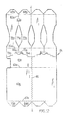
- an elongate wrapper blank 10 formed from paperboard or similar sheet material and which comprises a back panel 12, handle panel 14, handle panel 16, a top panel 18 and a front panel 20 hinged one to the next along transverse fold lines 22,24,26 and 28 respectively.
- the wrapper is suitable for packaging a single row of containers.
- the back panel 12 has hinged along its free transverse edge a base panel comprising a series of truncated triangular flaps 29 and 32 which are spaced apart from one another and hinged to the back panel 12 along a common score line 33.
- the front panel 20 has hinged along its free transverse edge a base panel comprising a series of truncated triangular flaps 34-37 which are spaced apart from one another and hinged to the front panel 20 along a common fold line 38.
- the handle panels 14 and 16 are of similar configuration to one another about the central transverse fold line 24 and include hand gripping apertures 39, 40, respectively, struck from the blank 10.
- the hand gripping aperture 39 is provided with a hinged hand cushioning flap 41 and the hand gripping aperture 40 is provided with a hinged hand cushioning flap 42.
- a glue flap 43 is hinged to the back panel 12 along transverse fold line 22 and projects into the hand gripping aperture 39 towards the hand cushioning flap 41.
- the top panel 18 is provided with a transversely extending tear-away strip 44 to facilitate opening the package.
- the front panel 20 is formed with three elongate apertures 45, 46 and 47 which are struck from the blank and shaped so as to form between them four similar waisted strips 48-51 extending longitudinally of the blank.
- the top panel 18 is formed with frangible zones comprising three spaced score lines 52, 53 and 54 which extend longitudinally of the blank and meet with one end of each of the apertures 45, 46 and 47 respectively.
- the front panel 20 is formed with frangible zones comprising three score lines 55, 56 and 57 which extend longitudinally of the blank from the opposite ends of the apertures 45, 46 and 47, respectively to the spaces between the adjacent truncated triangular flaps 34-37.
- the complete handle structure 58 ( Figures 2 and 4) is formed by first applying an application of glue to the handle panels 14 and 16 and the glue flap 43 after which the handle panels are then brought into face to face contact by folding about the transverse fold line 24 so that the two handle panels 14 and 16 are adhered tcgether, whereby the hand gripping apertures 39 and 40 are brought into register with one another. During this operation the glue flap 43 is passed through the hand gripping aperture 40 and adhered to the top panel 18.
- a further application of glue is then made to the top panel between tear-away strip 44 and fold line 28 and to all the truncated triangular flaps.
- the pre-glued blank is then wrapped about a row (in this case four) parallelapiped primary containers b' by causing the blank to be folded about transverse fold lines 22 and 28 so that the top panel 18 abuts and the glued area thereof is adhered to the top faces of the containers 'c' with the back panel 12 and front panel 20 extending perpendicularly thereto. Thereafter the two series of truncated triangular flaps 29-32 and 34-37 are folded about their respective transverse fold lines 33 and 38 and adhered to the bottom faces of each of the containers 'c'.
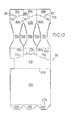
- the tear-away strip 44 is torn and removed so that the top panel 18 is divided into two portions whereafter the unglued part of the top panel 18 together with handle structure 58 and back panel 12 is hinged away from the series of primary containers 'c' and subsequently completely detached therefrom by tearing along the score line 33, as illustrated in Figures 4 and 5 of the drawings, so as to expose one side of each of the primary containers 'c' as shown in Figure 6 of the drawings.
- the primary containers may now be detached one from the next by pulling the containers apart so that the package tear- along the longitudinal score lines 52-54 and 55-57 between the adjacent strips 48-51 without destroying the strips.
- each individual container 'c' after detachment is thereby provided with one of the waisted strips 48-51 which extends between the top and base walls of the container so as to provide a handle by which the container may be grasped. It will be appreciated that once the container has been opened the handle thus provided facilitates pouring of the fluent contents as illustrated in F.igure 8 of the drawings.
- handle structure 58 comprising handle panels 14 and 16 may be omitted in which case the back panel 12 is directly hinged to the top panel 18.
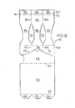
- Figure 9 shows an elongate wrapper blank 59 formed from paperboard or similar sheet material and which comprises a back panel 60 top panel 61 and a front panel 62 hinged one to the next along transverse fold lines 63 and 64 respectively.
- the back panel 60 has hinged along its free transverse edge a series of truncated triangular flaps 64, 65 and 66 which are spaced apart from one another and hinged to the back panel 60 along a common score line 67.
- the front panel 62 has hinged along its free transverse edge a series of truncated triangular flaps 68, 69 and 70 which are spaced apart from one another and hinged to the front panel 62 along a common fold line 71.
- An aperture 72 is struck from the top panel 61 from which extends a pair of divergent series of score lines 73, 74 respectively which terminate at the opposed longitudinal edges of the top panel 61.
- a tear-away panel is defined by the series of score lines 73, 74 and the transverse fold line 63, which facilitates opening the package.
- the front panel 62 is formed with two elongate apertures 75 and 76 which are struck from the blank 59 and shaped so as to form three similar waisted strips 77, 78 and 79 extending longitudinally of the blank.
- the top panel 61 is formed with frangible zones comprising two spaced score lines 80 and 81 of which score line 80 extends longitudinally of the. blank from the series of score lines 74 to meet with one end of the aperture 75.
- score line 81 extends longitudinally of the blank from the series of score lines 73 to meet with one end of aperture 76.
- the front panel 62 is formed with frangible zones comprising two score lines 82 and 83 aligned with score lines 80 and 81 respectively, and which also extend longitudinally of the blank from opposite ends of the apertures 75 and 76 respectively to the spaces between the adjacent truncated triangular flaps 68, 69 and 70.
- an application of glue is made to the top panel 61 in the area defined between the series of score lines 73 and 74 and the transverse fold line 64. Glue is further applied to all the truncated triangular flaps.
- the pre-glued blank is then wrapped about a row (in this case three) parallelapiped primary containers 'c' ( Figures 10 and 11) by causing the blank to be folded about transverse fold lines 63 and 64 so that the top panel 61 abuts, and the glued area thereof is adhered to, the top faces of the containers 'c' with the back panel 60 and front panel 62 extending perpendicularly thereto.
- the two series of truncated triangular flaps 64-66 and 68-70 are folded about their respective transverse fold lines 67 and 71 and adhered to the bottom faces of each of the containers 'c'.
- the package thus formed is illustrated in Figure 10. It will be appreciated that the two series of truncated triangular flaps are adhered along the bases of the primary packages in spaced relationship as described in the previous embodiment with reference to Figures 1 ta 8 of the drawings. Also, in common with the previous embodiment, the frangible zones i.e. score lines 80-83 are coincident with the gaps between adjacent containers.
- the tear away panel is grasped at aperture 72 and torn away along the series of score lines r3 and 74 so that the top panel 61 is divided into two portions whereafter the unglued part of the top panel 61 together with the back panel 60 is hinged away from the row of containers 'c' and subsequently completely detached therefrom by tearing along the score line 67.
- the package is shown partially open in Figure 11 of the drawings.
- the package now consists of a series of containers 'c' to which is attached the remaining portion of top panel 61, the front panel 62 (unglued) and both series of truncated triangular flaps.
- the primary containers 'c' may now be detached one from the next by pulling the containers apart so that the package tears along the longitudinal score lines 80, 81 and 82, 83 located between the adjacent strips 77, 78 and 79.
- Figure 12 of the drawings shows a further blank 84 for forming a package comprising a row of four parallelapiped primary containers.
- the blank 84 is symetrical about the centre line X-X and is similar in general construction to that described with reference to Figure 9 of the drawings. Hence, the features of the blank to the left-hand side of the centre line X-X have been enumerated with numerals designating similar parts to those illustrated in Figure 9 but with the addition of suffix 'a.'
- the package formed from the blank 84 is achieved in a manner similar to that described with reference to Figures 9 to 11 and it will also be appreciated that the package is opened in a like manner. However, a central score line 85 is provided along the centre line X-X so that the package may first be broken into two halves each containing a pair of primary containers which may then be separated from one another as previously described.
- the base panel comprising flaps 68b, 69b and 70b are rectangular in shape rather than triangular as previously described and are secured to the side walls of the containers rather than their bases.
- the transverse fold line 71b is intermittent so that the flaps 68b, 69b, and 70b are attached to respective ones of the waisted strips 77b, 78b and 79b by means of small tabs 87, 88 and 89 respectively.
- Tab 87 is hinged to the waisted strip 77b along a short fold line 90; tab 88 is hinged to waisted strip 78b along short fold line 91 and tab 89 is hinged to waisted strip 79b along short fold line 92.
- the fold line 71b is scored so that the flaps can be broken away from their respective waisted strips except at the hinged connection therebetween. It is envisaged that this modified base panel construction could be adopted in other embodiments of the invention described herein.
- the package illustrated in Figures 14 and 15 is formed in a manner similar to that previously described with reference to Figures 9 to 11. Likewise the package is opened and the containers separated from one another as described previously. However, the provision of the tabs 87, 88, and 89 permits the respective handles provided by the waisted strips to be bowed outwardly by virtue of the hinged connection between the tabs and the waisted strips. This feature is illustrated in Figure 15 of the drawings and allows .the handle of each container to be moved outwardly from its face to face engagement with the wall of the container and thereby makes it easier to grasp the handle strip, in use.
- the blank 93 illustrated in Figure 16 also includes a base panel comprising rectangular flaps 68c, 69c and 70c hinged to the waisted panels 77c, 78c and 79c respectively.
- the fold line 71 of the Figure 9 embodiment has been replaced by a pair of fold lines 71c, 71c' which define between them a shoulder panel 94 extending transversely across the blank.
- Each of the fold lines 71c and 71c' are deeply scored at spaced locations which coincide with the lower portion of each of the waisted panels 77c, 78c and 79c.
- the package illustrated in Figures 17 and 18 of the drawings is formed in a similar manner to that described with respect to the immediately preceding embodiment in that the flaps 68c, 69c and 70c are adhered to the side walls of their associated containers 'c' rather than the bases of those containers so that the flaps are located beneath lowr portions of the respective handle strips 77c, 78c and 79c.
- the shoulder panel 94 lies flat against the side walls of the containers as shown in Figure 17.
- the shoulder panel 94 is hinged into an upright position perpendicular to the adjacent side walls of the containers in order to permit each handle strip to move away from the side wall of its associated container so as to make it easier to grasp the handle.
- Shoulder panel 94 is shown in its upright position in Figure 18 of the drawings.
- the package comprises a wrapper 95 which passes only partially around the packed containers 'c' and does not include a back panel as in the previous embodiments.
- the wrapper 95 is formed from paperboard or similar sheet material and comprises a top panel 96 and a front panel 97 and a base panel 98 hinged one to the next along transverse fold lines 99 and 99' respectively.
- the top panel 96 is provided with a transversely extending tear-away strip 100 to facilitate opening the package.
- the front panel 97 is formed with three elongate apertures 101, 102 and 103 which are struck from the wrapper 95 and shaped so as to form four similar waisted strips 104, 105, 106 and 107 extending longitudinally of the wrapper.
- the top panel 96 is formed with three spaced score lines 108, 109 and 110 which extend longitudinally of the wrapper and meet with one end of each of the apertures 101, 102 and 103. respectively.
- the front panel 97 is formed with three score lines 111, 112 and 113 which are aligned with the score lines on the top panel 96 and extend longitudinally of the wrapper from the opposite ends of the apertures 101, 102 and 103 respectively to the spaces between adjacent truncated triangular flaps 114, 115, 116 and 117.
- the truncated triangular flaps together form the base panel 98 and are hinged to respective ones of the waisted strips along their common fold line 99'.
- an application of glue is made to the top panel on either side of the tear-away strip 100 and also to all the truncated triangular flaps.
- the pre-glsed wrapper 95 is then wrapped about a row (in this case four) parallelapiped primary containers 'c' by causing the wrapper to be folded about transverse fold lines 99 and 99' so that the top panel 96 abuts, and the glued areas thereof are adhered to, the top faces of the containers 'c' with the front panel 97 extending perpendicularly thereto. Thereafter, the truncated triangular flaps 114-117 are folded about the fold line 99' and adhered to the bottom faces of each of the containers 'c'.
- each individual container is provided with one of the waisted strips 104-107 which extends between the top and base walls of the container so as to provide a handle by which the container may be grasped.
- Figures 22 and 23 show schematically a method by which wrappers such as wrapper 95 may be applied to a continuous series of parallelapiped containers 'c'.
- An elongate blank 114 is coiled about a mandrill which may be driven by suitable means so that the blank is fed outwardly from the coil in a continuously moving wall as shown in Figure 22.
- the blank comprises the component parts of the wrapper illustrated in Figure 19 i.e. a top wall 96a, front wall 97a and base wall 98a comprising the truncated triangular flaps.
- the feed and position of the blank 114 is such that the blank is brought into side by side relationship with a line of containers 'c' to be packed.
- the top panel 96a and base panel 98a is adhered to the tops and bases of the containers, respectively, as previously described.
- the blank may then be severed at suitable locations to provide a series of units such as the package shown in Figure 19 of the drawings.
- the package illustrated in Figures 24 and 25 of the drawings is similar to that shown and described with reference to Figure 19 and like parts are designated like reference numerals with the addition of suffix 'b'.
- the wrapper 115 is not provided with a tear-away strip such as strip 100 previously referred to but, instead, in order to ensure that the integrity of the package is maintained, the whole package is overwrapped with suitable film material such as a heat shrunk plastics film material 116. In order to open the package the plastics film 116 is removed whereafter the containers 'c' may be detached one from the next by pulling the containers apart as previously described.
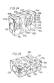
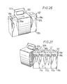
- Figures 26 and 27 illustrate a further package comprising wrapper 121 similar to that described with reference to Figures 24 and 25 and in which like parts are designated like reference numerals with the addition of the suffix 'c'.
- an outer sleeve 122 incorporating a handle structure 123 is overwrapped around the wrapper 121.
- the outer sleeve 122 may conveniently be formed from paperboard or other suitable material.
- FIG. 28-33 there is shown a further embodiment of the invention suitable for packaging two parallel rows of primary containers Cl and C2.
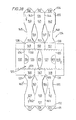
- Figure 28 shows an elongate blank 124 formed from paperboard or similar foldable sheet material and which comprises a top panel 125 having two similar central portions 126, 127 to the opposite side edges of which is joined a pair of opposite outer portions 128, 129 of the top wall.
- the outer portions 128, 129 are joined to the central portions of the top wall along score lines 130, 131 respectively.
- a pair of side flanges 132, 133 are hinged to the opposite end edges of the central portions 126, 127 along fold lines 134, 135 respectively.
- the blank 124 also includes a pair of side walls 136, 137 hinged to the outer portions of the top wall 128, 129 along fold lines 138, 139 respectively.
- the side wall 136 takes the form of three strips 140, 141 and 142 connected one to the next along score lines 143, and 144. Each of the side wall strips has a waisted zone between its ends formed by cut-out areas 145-148 of the side wall 136.
- the outer portion 128 of the top wall is formed by three panels 149, 150 and 151 separated by score lines 152 and 153 which are aligned with the score lines 143 and 144 respectively.
- a base panel 154 is hinged along a fold line 155.
- the base panel 154 takes the form of three truncated triangular tabs 156, 157 and 158 hinged to each of the strips 140, 141 and 142 respectively.
- the opposite side wall 137 is of similar construction to that of side wall 136 and includes side wall strips 159, 160 and 161 connected one to the next by means of score lines 162 and 163. Strips 159, 160 and 161 also have a waisted configuration provided by cut-out areas 162-165 of the side wall panel 137.
- the outer portion 129 of the top wall is formed by three panels 166, 167 and 168 separated by score lines 169, 170 which are aligned with the score lines 162 and 163. respectively.
- a base panel 171 is hinged to the side wall panel 137 along a fold line 172 and takes the form of three truncated triangular flaps 173, 174 and 175 hinged to each of the side wall strips 159, 160 and 161 respectively.
- a pair of arcuate tabs 176, 177 are struck from the central portions 126, 127. respectively, of the top wall panel 125.
- each of the outer portions 128 and 129 adhere to parts of the carton tops in each row and the side flanges are folded downwardly about their respective fold lines 134, 135 to engage and adhere to upper portions cf the sides of the end most cartons in each row.
- the side wall panels 136 and 137 are then folded downwardly about their fold lines 138, 139 respectively so that each of the strips 140, 141 and 142 lie adjacent the outwardly facing sides of the cartons in one row and each of the strips 159, 160 and 161 lie adjacent the outwardly facing sides of the cartons in the other row.
- each of the truncated triangular flaps 156-158 and 173-175 is adhered to a different one of the packaged cartons.
- the side flanges 132 and 133 assist in maintaining the two rows Cl, C2 of the cartons in their side-by-side relationship.
- the side flanges could be excluded in which case some other means of keeping the carton rows together would be provided.
- adhesive tape could be applied to the carton bases to hold the rows together.
- the bridging panel construction described with reference to Figure 38 hereafter could be utilized.
- arcuate tabs 176, 177 are displaced upwardly from central portions 126, 127 respectively, of the top wall panel so as to hinge about the fold lines 134 and 135.
- each of the top wall panels'126 and 127 are grasped by means of the central aperture 179 ( Figure 28) and pulled apart so that the sleeve is torn along score lines 130 and131.
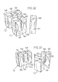
- Figure 31 both the central portions of the top wall panel, 126 and 127 are completely removed together with central areas of the side flanges 132 and 133 thereby facilitating the separation of the two rows Cl and C2 of cartons.
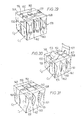
- Figure 32 of the drawings the cartons in row Cl are connected one to the next by the outer portions of the top wall 129 i.e.
- the cartons in row Cl may then be detached one from the next by tearing along the score lines 169 and 170 which separate the three panels 166, 167 and 168 and the score lines 162 and 163 which separate each of the side wall strips 159, 160 and 161.
- the carton 'X' Figure 33
- which is furnished with part 168 of top wall portion 129, and side wall strip 161 together with base flap 175 is detached from the adjacent carton by tearing along score lines 170 and 163 respectively.
- Other cartons in row Cl and also in row C2 are detached from one another in a similar manner.
- each individual carton after detachment is provided with one of the waisted side wall strips which extends between the top and base of the carton. Since the waisted strip is free for limited movement away from the carton side wall, the waisted strip itself provides a handle by which the carton may be grasped. It will be appreciated that once the carton has been opened the handle thus provided facilitates pouring of the fluent contents.
- This handle feature is particularly advantageous in that it dispenses with the necessity of grasping the carton by its side walls which tends to cause the fluent contents to spurt from the opening when the carton is grasped. It is thought that such a feature would enable even a large capacity carton of (say) 2 litres suitable for sale.
- the force applied to the side walls of such a large capacity carton, in order to grip the carton for pouring is such that spurting of the contents is a particular problem. By eliminating the necessity to grip the carton by its side walls, the problem of such uneven flow is greatly minimized.
- Figures 34 to 36 of the drawings illustrate a further embodiment of the invention for packaging two parallel rows of primary containers 'c'.
- Figures 34 shows an elongate wrapper blank 180 formed from paperboard or similar sheet material and which comprises a back panel 181, a top panel generally designated reference numeral 152 and a front panel 183 hinged one to the next along transverse score lines 184, 185 respectively.
- the top panel 182 consists of two similar handle panels 186, 187 respectively connected together centrally of the blank by means of a bridging panel 188 along transverse fold lines 189, 190 respectively.
- the top panel 182 further consists of a pair of similar outer portions 191, 192 respectively.
- Outer portion 191 is hinged to the handle panel 186 along a transverse score line 193 and the outer portion 192 is hinged to handle panel 187 along transverse score line 194.
- the outer portion 191 of the top wall and the back wall 181 are hinged together along the score line 184 and similarly the outer portion 192 of the top panel and the front wall 183 are hinged together along the transverse score line 185.
- the handle panel 186 has struck therefrom a central hand gripping aperture 195 and likewise the handle panel 187 has struck therefrom a central hand gripping aperture 196.
- the back panel 181 takes the form of three panels 197, 198 and 199 each of which panels has a waisted zone between its ends formed by hinged flaps 202, 203; 204,205; and 206, 207.
- the outer portion 191 of the top panel 182 also is formed by three panels 208, 209 and 210 separated from one another by score lines 211, 212 which are aligned with score lines 200, 201 respectively.
- a base panel 213 is hinged along a fold line 214.
- the base panel 213 takes the form of three truncated triangular flaps 215, 216 and 217 hinged to each of the panels 197, 198 and 199 respectively.
- the opposite front wall of the blank is of similar construction to that of back wall 181 and includes panels 218, 219 and 220 connected one to the next by means of score lines 221 and 222.
- Panels 218, 219 and 220 also have a waisted configuration provided by hinged flaps 223, 224; 225, 226; and 227, 228.
- the outer portion 192 of the top wall panel 182 is formed by three panels 229, 230 and 231 separated from one another by means of score lines 232, 233 which are aligned with the score lines 221 and 222 respectively.
- a base panel 234 is hinged along fold line 235.
- the base panel 234 takes the form of three truncated triangular flaps 236, 237 and 238 hinged to each of the panels 218, 219 and 220 res pectively.
- the bridging panel 188 is then folded about the transverse fold lines 189, 190 so as to bring the adjacent edges of the two handle panels 186 and 187 into overlapping relationship.
- the top wall panel 182 is brought into overlying engagement with the tops of the cartons so that each of the outer portions 191, 192 adhere to parts of the carton tops in respective rows Cl, C2 and the front and back wall panels 181, 183 are folded downwardly about their respective score lines 184, 185.
- each of the panels 197-199 lie adjacent to the outwardly facing sides of the cartons in one row and each of the panels 218-220 lie adjacent the outward facing sides of the cartons in the other row.
- the base panels 213, 234 are then folded.about their respective fold lines 214, 235 to engage the bases of the cartons.
- each of the truncated triangular flaps 215-217 and 236-238 is adhered to adifferent one of the packaged cartons. It is envisaged that some means of keeping the carton rows together at their bases would be provided. For example, adhesive tape could be applied to the carton bases to hold the rows together. Alternatively, the bridging panel construction described with reference to Figure 38 hereafter could be utilized.
- the cartons in row Cl may then be detached one from the next by tearing along the score lines 211 and 212 which separate the three panels 208, 209 and 210and simultaneously tearing along the score lines 200 and 201 which separate each of.the panels 197, 198 and 199.
- the cartons in row C2 may be detached one from the next in a similar manner.
- Each individual carton after detachment is provided with, one of the waisted side wall panels which extends between the top and base of the carton.
- the flaps hinged to the waisted panel e.g. flap 202 and 203 of panel 197 are folded inwardly towards one another about their respective fold lines thereby forming a strong two-ply handle which is free for limited movement away from the carton side wall.
- Figure 37 illustrates a wrapper blank 240 which is similar to the blank illustrated in Figure 34 and in which like parts designate like reference numerals with the addition of the suffix 'a'.
- hinged flaps 202-207 and 223-228 of Figure 34 have been completely struck from the blank as in other prior embodiments described thus leaving a pair of apertures 241 to 242 in the front wall panel 181a and a pair of apertures 243, 244 in the front wall panel 183a.
- FIG. 38 of the drawings A further wrapper blank 245 is illustrated in Figure 38 of the drawings which is similar to the blank illustrated in Figure 37 and in which like parts are designated like reference numerals with the addition of the suffix 'b'.
- Blank 245 has a modified top panel 182b and a modified base panel 213b.
- handle panels 186a and 187a of blank 240 have been replaced by a single handle panel 246.
- the handle panel 246 is connected to the outer portions 191b and 192b of the top wall panel 182b. by means of tear-away strips 193b and 194b respectively.
- Hand gripping apertures 247 and 248 are struck from the handle panel 246 and extend longitudinally of the blank.
- the hand gripping apertures are supplemented by a pair of foldable reinforcement panels 149,150 which are hinged adjacent respective ones of the hand gripping apertures 247, 248.
- the reinforcement panels 249, 250 are folded towards one another into overlapping relationship with the underside of the handle panel 246 and thereby provide a strengthened two-ply handle 251 located between the hand gripping apertures 247 and 248.
- the modification provided by the base panel 213b is that the central flap 216b has been extended to form a bridging panel 252 hinged to the flap 216b along a transverse fold line 253 and which terminates in an anchor flap 254 which is hinged to the bridging piece 252 along a transverse fold line 255.
- FIG. 39 to 411 A further embodiment of the invention is shown in Figures 39 to 411 which is particularly suitable for the packaging of a plurality of bottles particularly, although not exclusively, bottles formed from a plastics material.
- Some bottles of this type have soft walls which can make it difficult to pour the contents of the bottle evenly when the walls are grasped.
- Figure 39 illustrates an elongate wrapper blank 256 formed from paperboard or similar sheet material, the central part of which comprises a top panel 257 formed with a pair of spaced circular- apertures 258, 259 respectively to receive the neck portions; of a pair of bottles to be packaged.
- a side wall 260 is hinged to one transverse edge of the top wall 257 along a transverse fold line 261 and a further side wall 262 is hinged to the opposite transverse edge of top wall 257 along transverse fold line 263.
- Sicde wall 260 comprises a pair of waisted panels 264, 265 which are connected to one another along a central longitudinal score lirne 266.
- the waisted zones of panels 264 and 265 are defined boy recesses 267, 268 and central aperture 269.
- a lower inclined side wall 270 is contiguous with side wall 265 and hinged thereto along a transverse fold line 271.
- the lower inclined side wall 270 is formed with two spaced, arcuate apertures 272, 273 which are aligned with the neck receiving apertures 258, 259 respectively.
- a pair of spaced glue flaps 274, 275 is hinged to the lower inclined side wall 270 along a transverse fold line 276.
- the side wall 262 comprises a pair of waisted panels 277, 278 connected together along a central longitudinal score line 279 and have their waisted zones defined by recesses 280, 281 and central aperture 282.
- a lower inclined side wall 283 is contiguous with the side wall 262 and is hinged thereto along a transverse fold line 284.
- Arcuate apertures 285 and 286 which are aligned with the neck receiving apertures 258 and 259 respectively are struck from the lower inclined side wall panel 283.
- Glue flaps 287, 288 are hinged to the lower inclined side wall 283 along a transverse fold line 289.
- a central tear strip 290 extends longitudinally across the top wall panel 257 between the neck receiving apertures 258 and 259 and connects together the adjacent ends of apertures 269 and 282.
- the wrapper blank 256 is presented to the bottles so that neck portions of the bottles are received in the neck receiving apertures 258 and 259 respectively.
- the side walls 260, 262 are then folded about transverse fold lines 261, 263 respectively so that they extend alongside the sides of the bottles and subsequently the glue flaps 274, 275 and 287, 288 are brought into overlapping relationship beneath the bottle bases.
- the lower inclined side wall 270 adopts its inclined position by folding about transverse fold lines 271 and 276 whereby heel portions of each of the bottles are received in the arcuate apertures 272 and 273.
- the lower inclined side wall 283 is brought into its inclined position by folding about transverse fold lines 284 and 289 whereby diametrically opposed heel portions of each of the bottles are received in arcuate apertures 285, 286.
- Glue flaps 274 and 287 are adhered together in overlapping relationship and likewise glue flap 275 is overlapped with and adhered to glue flap 288.
- the central tear strip 290 is torn from the blank thus dividing the top wall 257 of the package.
- the bottles may then be grasped and moved apart so that the package tears along longitudinal score lines 266 and 279 whereby the bottles Bl and B2 become separated from one another.
- each bottle retains a sleeve like wrapper 291, 292 of the original package.
- the wrapper 291 includes the waisted pa-els 264 and 277, either of which provides a handle by which the bottle may be grasped and manipulated to facilitate pouring of the contents of the bottle.
- the wrapper 292 includes the waisted panels 265 and 278 either of which may be used as pouring handles.
- transverse fold lines 293, 294 extend across the side wall panels 260 and 262 respectively in order to allow the handle panels to bow outwardly when grasped.
- FIG. 42 to 44 of the drawings A further embodiment of the invention is illustrated in Figures 42 to 44 of the drawings, which is suitable for packaging a plurality of theremoformed flanged cups or similar containers.
- FIG. 42 of the drawings there is shown an elongate wrapper blank 295 formed from paperboard or similar sheet material and which comprises a top wall panel 296 from which is struck a central star-shaped aperture 297.
- a central tear-away strip 298 extends from opposed edges of the central aperture 297 to the opposite longitudinal side edges of the blank 295.
- a pair of similar side wall panels 299, 300 is hinged to the opposed transverse edges of the top panel 296 along transverse fold lines 301, 302 respectively.
- the side wall panel 299 comprises a pair of waisted panels 303, 304 which are connected together along a central longitudinal score line 305.
- the waisted zones of the panel 303, 304 are defined by arcuate recesses 306 and 307 and a central circular aperture 308.
- a pair of glue flaps 309, 310 is hinged to the free transverse edge of side wall panel 299 along transverse fold lines 311, 312 respectively.
- the side wall panel 300 comprises a pair of waisted panels 313, 314 which are connected together along a central longitudinal score line 315.
- the waisted zones of panels 313 and 314 are defined by arcuate recesses 316, 317 and central circular aperture 318.
- a pair of glue flaps 319, 320 is hinged to the free transverse edge of side wall panel 300 along fold lines 321 and 322 respectively.
- a central longitudinal score line 323 which is aligned with score lines 305 and 315 extends across the top wall panel 296 and connects together the central star-shaped aperture 297 with each of the circular apertures 308 and 318.
- the tear strip 298 is torn thereby dividing the top panel 296 and hence the package into two halveswith each half comprising a pair of cups.
- the individual cups of each pair e.g. cups Cl and C2 may then be separated by pulling the cups away from one another so that the blank tears along the central score line 323 and the score line (305) which connects together the waisted panels.
- Each individual cup then comprises part of the top wall panel 296, a waisted side wall panel which provides a handle for the cup, and a glue flap.
- the original too wall panel 296 is divided into four quarters each of which includes a triangular recess comprising a part of the original star-shaped aperture 297.
- the triangular recess permits access to the lid of the cup which may be torn in the area of the recess thereby providing a pouring aperture from which the contents can be dispensed.
- cup Cl has a triangular recess 't' but with the lid of the cup intact whereas the cup C2 has a portion of its lid torn away in the area of the triangular recess.
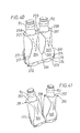
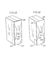
- the carton Cl shown in Figure 45 of the drawings incorporates a handle panel 325 which comprises a waisted panel 326 extending between the top and the base of the carton along one of the narrow side walls of the carton.
- the waisted zone of panel 326 is defined by a pair of similar apertures 327, 328 struck from the handle panel 325.
- the handle panel further includes and is adhesively secured to the carton 'Cl' by means of integral glue flaps 329, 330 which are secured to the broad side walls of the carton.
- the carton 'C2' incorporates a similar handle panel 331 but in which the side flaps do not extend along the whole height of the carton.
- the waisted zone of panel' 332 is defined by recesses 333, 334 respectively and the handle panel 332 is attached to the carton by means of glue flaps 335-338.
- the waisted panel 326a includes a top portion which initially is tucked beneath a top band 339 of the handle panel 325a.
- the tuck is formed by a pair of closely spaced parallel fold lines 340, 341 and this feature permits some extra limited movement of the waisted panel 326a away from the adjacent side wall of the carton C3 to provide more space therebetween when the carton is grasped by the handle.
- Figures 48 and 48a also show a construction which is similar to that of the immediately preceding embodiment in that means is provided to permit extra limited outward movement of the handle. Again; like parts are designated like reference numerals but with the addition of the suffix 'b'.
- the handle.panel 325b is secured to the carton 'C4' not only by the glue flaps 329b and 330b but also by upper and lower bands 339b and 342 respectively. At its lower and the waisted panel 326b is hinged to the band 342 along closely spaced parallel fold lines 340, 344 respectively.
- FIG. 49 of the drawings there is an alternative carton and handle arrangement.
- a handle panel 246 is secured to a carton 'C5' alongside one of the broad side walls of the carton unlike previous embodiments where the handle panel is secured to the narrow side wall of the carton.
- Handle panel 346 comprises a waisted central panel 347 extending between the top and base walls of the carton and in which the waisted zone is defined by arcuate recesses 348, 349 respectively.
- the handle panel 346 is secured to carton ' C 5' by means of a top glue flap 348 secured to the top wall of the carton and a lower glue flap (not shown) secured to the base wall of the carton.
- This arrangement is, of course, suitable for use in a multipack as described previously and the handle strip for each container may, of course, be applied in a manner described with reference to Figures 22 and 23.
- wrappers glueing of the wrappers to the containers is specifically referred to it is envisaged that other means of securing the wrappers to the containers may be utilized.
- the wrappers suitably treated may be secured by thermosealing.
- a weakened area to produce an aperture may be present on the top face of each container. Such weakened area may be punctured to form an aperture to permit ingress of aix into the container during pouring so as to further aid even-flow dispensing.
- An aperture in the wrapper may be required to allow access to the weakened area of the carton or the weakened area may be positioned beneath the removable portion (when present) of the wrapper top panel.
- the base panels of the wrappers may be overlapped and secured together by suitable interengaging locking elements.
- suitable interengaging locking elements such as the punch-locks disclosed in U.S. Patent No. 4,077,095 or the locking means disclosed in U.S. Patent No. 3,249,284 may be used for this purpose.
- the glue may be applied to the underlying portions of the containers themselves rather than being applied to the wrappers.
- base flaps which are spaced apart from one another i.e. the truncated triangular flaps
- adjacent flaps may be joined together by a line of weakness as by scoring so that the base flaps can be separated one from the next as the containers are pulled apart.
- the term 'division' between respective ones of said base flaps is to be interpreted as meaning a space or a frangible connection (such as a score line) between adjacent flaps.
Abstract
Description
- This invention relates to a package accommodating a plurality of uniform primary containers particularly, although not exclusively, containers of the type loaded with fluent contents and sealed for storage or disposal. The invention also relates to wrappers for forming such a package.
- A recent trend in the packing of fluids such as milk and fruit juices has been to utilize sealed fluidtight parallelapiped cartons and soft plastics bottles. These containers are convenient and relatively inexpensive but do have the disadvantage, in use, that when the sides of the container are grasped for pouring, the fluent contents tend to spurt from the opening or mouth of the container'.
- The present invention not only provides a convenient package in which a number of such containers can be accommodated within a wrapper to form a multi-pack unit, but also permits parts of the wrapper to remain, and provide a handle for each container when the package is opened. This latter feature is particularly advantageous in that it dispenses with the necessity of grasping a container by its sides and so greatly minimizes the problem of uneven flow when the contents of the container are dispensed.
- One aspect of the present invention provides a package comprising a plurality of containers arranged in at least one row, the package having a wrapper of foldable sheet material which includes, for each container, a strip of material extending between upper and lower ends of one face of that container to provide a handle by which the container can be grasped, said handle strip lying adjacent to, but detached from the container, characterized in that adjacent containers in each row detachably are connected together by their respective handle strips, and in that at least one frangible zone is provided between neighbouring strips to permit detachment of one container from the adjacent container without destroying said handle strip.
- Some embodiments of the invention will now be described, by way of example, with reference to the accompanying drawings, in which:-
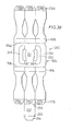
- Figure 1 is a plan view of a wrapper blank for forming a package according to the invention suitable for accommodating a single row of uniform containers,
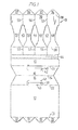
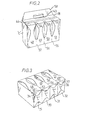
- Figures 2 and 3 are perspective views of a package utilizing the wrapper shown in Figure 1,
- Figures 4 to 8 are perspective views of the package showing successive steps taken to open the package,
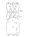
- Figure 9 is a plan view of another wrapper blank for forming a package according to the invention,
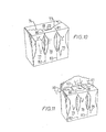
- Figures 10 and 11 are perspective views of a package utilizing the wrapper shown in Figure 9 and in which Figure 11 shows the package partially opened,
- Figure 12 is a plan view of a wrapper blank similar to that shown in Figure 9,
- Figure 13 is a plan view of another wrapper blank similar to that shown in Figure 9,
- Figures 14 and 15 are perspective views of a package utiizing the wrapper shown in Figure 13,
- Figure 16 is a plan view of yet another wrapper blank similar to that shown in Figure 9,
- Figures 17 and 18 are perspective views of a package utilizing the wrapper shown in Figure 16,
- Figures 19 to 21 are perspective views of a modified package according to the invention having a wrapper suitable for accommodating a single row of uniform containers and in which Figure 21 shows the package partially open,
- Figures 22 and 23 illustrate schematically a method by which a wrapper blank is applied to a series of containers to form packages similar to that shown in Figures 19 to 21,
- Figures 24 and 25 are perspective views of a modified package which is similar to that shown in Figures 19 to 21,
- Figures 26 and 27 are perspective views of a further modified package which also is similar to that shown in Figures 19 to 21,
- Figure 28 is a plan view of another wrapper blank according to the invention and which is suitable for accommodating two rows of uniform containers,
- Figures 29 to 33 are perspective views of a package formed from the wrapper blank illustrated in Figure 28 showing successive steps taken to open the package,
- Figure 34 is a plan view of-another wrapper blank suitable for accommodating two rows of uniform containers,
- Figures 35 and 36 are perspective views of a package formed from the wrapper blank shown in Figure 34 and in which Figure 36 shows the oackage partially onened,
- Figure 37 is a plan view of another wrapper blank similar to that shown in Figure 34,
- Figure 38 is a plan view of a modified wrapper blank similar to that shown in Figure 37,
- Figure 39 is a plan view of a further wrapper blank according to the invention and which is suitable for packaging a pair of similar bottles,
- Figures 40 and 41 are perspective views of a package utilizing the wrapper blank shown in Figure 39 and in which Figure 41 shows the package partially opened,
- Figure 42 is a plan view of a still further wrapper blank according to the invention and which is suitable for packaging a plurality of thermoformed cups,
- Figures 43 and 44 are perspective views of a package utilizing the wrapper blank shown in Figure 42 and in which Figure 44 shows the package partially opened, and
- Figures 47-49 are perspective views of a series of single containers having handle strips applied thereto.
- Referring to the drawings and first to Figure 1 thereof, there is shown an elongate wrapper blank 10 formed from paperboard or similar sheet material and which comprises a
back panel 12, handlepanel 14,handle panel 16, atop panel 18 and afront panel 20 hinged one to the next alongtransverse fold lines - The
back panel 12 has hinged along its free transverse edge a base panel comprising a series of truncatedtriangular flaps back panel 12 along acommon score line 33. Similarly, thefront panel 20 has hinged along its free transverse edge a base panel comprising a series of truncated triangular flaps 34-37 which are spaced apart from one another and hinged to thefront panel 20 along acommon fold line 38. - The
handle panels transverse fold line 24 and includehand gripping apertures hand gripping aperture 39 is provided with a hinged hand cushioning flap 41 and thehand gripping aperture 40 is provided with a hingedhand cushioning flap 42. Aglue flap 43 is hinged to theback panel 12 along transverse fold line 22 and projects into thehand gripping aperture 39 towards the hand cushioning flap 41. - The
top panel 18 is provided with a transversely extending tear-away strip 44 to facilitate opening the package. - The
front panel 20 is formed with threeelongate apertures - The
top panel 18 is formed with frangible zones comprising three spacedscore lines apertures front panel 20 is formed with frangible zones comprising threescore lines apertures - In order to form the package the complete handle structure 58 (Figures 2 and 4) is formed by first applying an application of glue to the
handle panels glue flap 43 after which the handle panels are then brought into face to face contact by folding about thetransverse fold line 24 so that the twohandle panels hand gripping apertures glue flap 43 is passed through thehand gripping aperture 40 and adhered to thetop panel 18. - A further application of glue is then made to the top panel between tear-
away strip 44 andfold line 28 and to all the truncated triangular flaps. The pre-glued blank is then wrapped about a row (in this case four) parallelapiped primary containers b' by causing the blank to be folded abouttransverse fold lines 22 and 28 so that thetop panel 18 abuts and the glued area thereof is adhered to the top faces of the containers 'c' with theback panel 12 andfront panel 20 extending perpendicularly thereto. Thereafter the two series of truncated triangular flaps 29-32 and 34-37 are folded about their respectivetransverse fold lines handle structure 58 is upstanding from thetop panel 18 at the junction between thetop panel 18 and theback panel 12.. As shown in Figure 3 the two series of truncated triangular flaps are adhered along the bases of the primary packages in spaced relationship. Hence, the frangible zones of the wrapper, that is, score lines 52-57 are coincident with the gaps between adjacent containers. - In order to open the package the tear-
away strip 44 is torn and removed so that thetop panel 18 is divided into two portions whereafter the unglued part of thetop panel 18 together withhandle structure 58 andback panel 12 is hinged away from the series of primary containers 'c' and subsequently completely detached therefrom by tearing along thescore line 33, as illustrated in Figures 4 and 5 of the drawings, so as to expose one side of each of the primary containers 'c' as shown in Figure 6 of the drawings. - Referring now to Figure 7 of the drawings it will be seen that after this procedure the package now consists of a row of primary containers 'c' to which is attached the remaining portion of the
top panel 18, the front panel 20 (unglued) and both series of truncated triangular flaps. - The primary containers may now be detached one from the next by pulling the containers apart so that the package tear- along the longitudinal score lines 52-54 and 55-57 between the adjacent strips 48-51 without destroying the strips.
- As shown in Figure 8 of the drawings each individual container 'c' after detachment is thereby provided with one of the waisted strips 48-51 which extends between the top and base walls of the container so as to provide a handle by which the container may be grasped. It will be appreciated that once the container has been opened the handle thus provided facilitates pouring of the fluent contents as illustrated in F.igure 8 of the drawings.
- In a further embodiment of the invention (not shown) it is envisaged that the
handle structure 58 comprisinghandle panels back panel 12 is directly hinged to thetop panel 18. - Referring now to Figures 9-12 of the drawings, there is shown another embodiment of the invention for packaging a single row of primary containers. Figure 9 shows an elongate wrapper blank 59 formed from paperboard or similar sheet material and which comprises a
back panel 60top panel 61 and afront panel 62 hinged one to the next alongtransverse fold lines - The
back panel 60 has hinged along its free transverse edge a series of truncatedtriangular flaps back panel 60 along acommon score line 67. Similarly, thefront panel 62 has hinged along its free transverse edge a series of truncatedtriangular flaps front panel 62 along a common fold line 71. - An
aperture 72 is struck from thetop panel 61 from which extends a pair of divergent series ofscore lines top panel 61. Thus, a tear-away panel is defined by the series ofscore lines transverse fold line 63, which facilitates opening the package. - The
front panel 62 is formed with twoelongate apertures waisted strips - The
top panel 61 is formed with frangible zones comprising two spacedscore lines line 80 extends longitudinally of the. blank from the series ofscore lines 74 to meet with one end of theaperture 75. Likewise scoreline 81 extends longitudinally of the blank from the series ofscore lines 73 to meet with one end ofaperture 76. Similarly, thefront panel 62 is formed with frangible zones comprising twoscore lines score lines apertures triangular flaps - In order to form the package, an application of glue is made to the
top panel 61 in the area defined between the series ofscore lines transverse fold line 64. Glue is further applied to all the truncated triangular flaps. The pre-glued blank is then wrapped about a row (in this case three) parallelapiped primary containers 'c' (Figures 10 and 11) by causing the blank to be folded abouttransverse fold lines top panel 61 abuts, and the glued area thereof is adhered to, the top faces of the containers 'c' with theback panel 60 andfront panel 62 extending perpendicularly thereto. Thereafter, the two series of truncated triangular flaps 64-66 and 68-70 are folded about their respectivetransverse fold lines 67 and 71 and adhered to the bottom faces of each of the containers 'c'. The package thus formed is illustrated in Figure 10. It will be appreciated that the two series of truncated triangular flaps are adhered along the bases of the primary packages in spaced relationship as described in the previous embodiment with reference to Figures 1 ta 8 of the drawings. Also, in common with the previous embodiment, the frangible zones i.e. score lines 80-83 are coincident with the gaps between adjacent containers. - In order to open the package the tear away panel is grasped at
aperture 72 and torn away along the series of score lines r3 and 74 so that thetop panel 61 is divided into two portions whereafter the unglued part of thetop panel 61 together with theback panel 60 is hinged away from the row of containers 'c' and subsequently completely detached therefrom by tearing along thescore line 67. The package is shown partially open in Figure 11 of the drawings. - As is the case for the previous embodiment the package now consists of a series of containers 'c' to which is attached the remaining portion of
top panel 61, the front panel 62 (unglued) and both series of truncated triangular flaps. - The primary containers 'c' may now be detached one from the next by pulling the containers apart so that the package tears along the
longitudinal score lines adjacent strips - Figure 12 of the drawings shows a further blank 84 for forming a package comprising a row of four parallelapiped primary containers. The blank 84 is symetrical about the centre line X-X and is similar in general construction to that described with reference to Figure 9 of the drawings. Hence, the features of the blank to the left-hand side of the centre line X-X have been enumerated with numerals designating similar parts to those illustrated in Figure 9 but with the addition of suffix 'a.' The package formed from the blank 84 is achieved in a manner similar to that described with reference to Figures 9 to 11 and it will also be appreciated that the package is opened in a like manner. However, a
central score line 85 is provided along the centre line X-X so that the package may first be broken into two halves each containing a pair of primary containers which may then be separated from one another as previously described. - Referring now to Figures 13 to 15 of the drawings, a further embodiment of the invention is shown.
- The blank 86 shown in Figure 13 of the drawings is similar to that illustrated in Figure 9 and like parts have been designated like reference numerals with the addition of the suffix 'b'. However, in this embodiment, the base
panel comprising flaps transverse fold line 71b is intermittent so that theflaps waisted strips small tabs Tab 87 is hinged to thewaisted strip 77b along ashort fold line 90;tab 88 is hinged towaisted strip 78b alongshort fold line 91 andtab 89 is hinged towaisted strip 79b alongshort fold line 92. In other areas thefold line 71b is scored so that the flaps can be broken away from their respective waisted strips except at the hinged connection therebetween. It is envisaged that this modified base panel construction could be adopted in other embodiments of the invention described herein. - The package illustrated in Figures 14 and 15 is formed in a manner similar to that previously described with reference to Figures 9 to 11. Likewise the package is opened and the containers separated from one another as described previously. However, the provision of the
tabs - The embodiment shown with reference to Figures 16 to 18 of the drawings also is similar to the previous embodiment described with reference to Figures 9 to 11 and therefore like parts are designated like reference numerals with the addition of the suffix 'c'. As with the immediately preceding embodiment this package also has a handle construction which provides for some extra limited movement of the handle strips away from the sides of the packaged containers. Again this modified base panel construction would be adopted in other embodiments of the invention.
- The blank 93 illustrated in Figure 16 also includes a base panel comprising
rectangular flaps waisted panels fold lines shoulder panel 94 extending transversely across the blank. Each of thefold lines waisted panels - The package illustrated in Figures 17 and 18 of the drawings is formed in a similar manner to that described with respect to the immediately preceding embodiment in that the
flaps respective handle strips shoulder panel 94 lies flat against the side walls of the containers as shown in Figure 17. However, when the handle strip of a container is grasped theshoulder panel 94 is hinged into an upright position perpendicular to the adjacent side walls of the containers in order to permit each handle strip to move away from the side wall of its associated container so as to make it easier to grasp the handle.Shoulder panel 94 is shown in its upright position in Figure 18 of the drawings. - Referring now to Figures 19-21 of the drawings there is shown a further embodiment of the invention but in which the package comprises a wrapper 95 which passes only partially around the packed containers 'c' and does not include a back panel as in the previous embodiments. The wrapper 95 is formed from paperboard or similar sheet material and comprises a
top panel 96 and afront panel 97 and abase panel 98 hinged one to the next alongtransverse fold lines 99 and 99' respectively. - The
top panel 96 is provided with a transversely extending tear-away strip 100 to facilitate opening the package. - The
front panel 97 is formed with threeelongate apertures waisted strips - The
top panel 96 is formed with three spacedscore lines apertures front panel 97 is formed with threescore lines top panel 96 and extend longitudinally of the wrapper from the opposite ends of theapertures triangular flaps base panel 98 and are hinged to respective ones of the waisted strips along their common fold line 99'. - In order to form the package an application of glue is made to the top panel on either side of the tear-
away strip 100 and also to all the truncated triangular flaps. The pre-glsed wrapper 95 is then wrapped about a row (in this case four) parallelapiped primary containers 'c' by causing the wrapper to be folded abouttransverse fold lines 99 and 99' so that thetop panel 96 abuts, and the glued areas thereof are adhered to, the top faces of the containers 'c' with thefront panel 97 extending perpendicularly thereto. Thereafter, the truncated triangular flaps 114-117 are folded about the fold line 99' and adhered to the bottom faces of each of the containers 'c'. - In order to open the package the tear away
strip 100 is torn and removed so that thetop panel 96 is divided into two parts. As shown in Figure 21 of the drawings it will be seen that after this procedure the package consists of a row of primary containers 'c' to which is attached the remaining portions of thetop panel 96, the front panel 97 (unglued) and the series of truncated triangular flaps. The containers 'c' may now be detached one from the next by pulling the containers apart so that the package tears along the score lines 108, 109 and 110 and scorelines - Figures 22 and 23 show schematically a method by which wrappers such as wrapper 95 may be applied to a continuous series of parallelapiped containers 'c'. An elongate blank 114 is coiled about a mandrill which may be driven by suitable means so that the blank is fed outwardly from the coil in a continuously moving wall as shown in Figure 22. The blank comprises the component parts of the wrapper illustrated in Figure 19 i.e. a
top wall 96a,front wall 97a andbase wall 98a comprising the truncated triangular flaps. - The feed and position of the blank 114 is such that the blank is brought into side by side relationship with a line of containers 'c' to be packed. After suitable application of adhesive the
top panel 96a andbase panel 98a is adhered to the tops and bases of the containers, respectively, as previously described. The blank may then be severed at suitable locations to provide a series of units such as the package shown in Figure 19 of the drawings. - The package illustrated in Figures 24 and 25 of the drawings is similar to that shown and described with reference to Figure 19 and like parts are designated like reference numerals with the addition of suffix 'b'. However, the
wrapper 115 is not provided with a tear-away strip such asstrip 100 previously referred to but, instead, in order to ensure that the integrity of the package is maintained, the whole package is overwrapped with suitable film material such as a heat shrunkplastics film material 116. In order to open the package theplastics film 116 is removed whereafter the containers 'c' may be detached one from the next by pulling the containers apart as previously described. - Figures 26 and 27 illustrate a further
package comprising wrapper 121 similar to that described with reference to Figures 24 and 25 and in which like parts are designated like reference numerals with the addition of the suffix 'c'. However, in this arrangement instead of utilizing a heat shrunk film in order to maintain the integrity of the package, anouter sleeve 122 incorporating ahandle structure 123 is overwrapped around thewrapper 121. Theouter sleeve 122 may conveniently be formed from paperboard or other suitable material. - Referring now to Figures 28-33 there is shown a further embodiment of the invention suitable for packaging two parallel rows of primary containers Cl and C2.
- Figure 28 shows an elongate blank 124 formed from paperboard or similar foldable sheet material and which comprises a
top panel 125 having two similarcentral portions outer portions outer portions score lines 130, 131 respectively. A pair ofside flanges central portions fold lines - The blank 124 also includes a pair of
side walls top wall fold lines side wall 136 takes the form of threestrips score lines side wall 136. Similarly, theouter portion 128 of the top wall is formed by threepanels score lines score lines base panel 154 is hinged along afold line 155. Thebase panel 154 takes the form of three truncatedtriangular tabs strips - The
opposite side wall 137 is of similar construction to that ofside wall 136 and includes side wall strips 159, 160 and 161 connected one to the next by means ofscore lines Strips side wall panel 137. Theouter portion 129 of the top wall is formed by threepanels score lines score lines base panel 171 is hinged to theside wall panel 137 along afold line 172 and takes the form of three truncatedtriangular flaps - To facilitate carrying the completed package, a pair of
arcuate tabs central portions top wall panel 125. - Referring now to Figure 29 of the drawings, in order to form the completed
package 178, as illustrated, two rows Cl and C2 of cartons are brought together in side-by-side relationship with three cartons in each row. Thepaperboard blank 124 is then wrapped about the two rows of cartons after first causing an application of glue to be made to theouter portions top wall panel 125 and also to theside flanges top wall panel 125 is brought into overlying engagement with the tops of the cartons each of theouter portions respective fold lines side wall panels fold lines strips strips base panels fold lines side flanges - In order to facilitate the manipulation of the completed package the
arcuate tabs central portions fold lines - Referring now to Figure 30 of the drawings, in order to open the package each of the top wall panels'126 and 127 are grasped by means of the central aperture 179 (Figure 28) and pulled apart so that the sleeve is torn along score lines 130 and131. As shown in Figure 31 both the central portions of the top wall panel, 126 and 127 are completely removed together with central areas of the
side flanges top wall 129 i.e. bypanels - The cartons in row Cl may then be detached one from the next by tearing along the
score lines panels score lines part 168 oftop wall portion 129, andside wall strip 161 together withbase flap 175 is detached from the adjacent carton by tearing alongscore lines - As shown in Figure 33 of the drawings each individual carton after detachment is provided with one of the waisted side wall strips which extends between the top and base of the carton. Since the waisted strip is free for limited movement away from the carton side wall, the waisted strip itself provides a handle by which the carton may be grasped. It will be appreciated that once the carton has been opened the handle thus provided facilitates pouring of the fluent contents. This handle feature.is particularly advantageous in that it dispenses with the necessity of grasping the carton by its side walls which tends to cause the fluent contents to spurt from the opening when the carton is grasped. It is thought that such a feature would enable even a large capacity carton of (say) 2 litres suitable for sale. The force applied to the side walls of such a large capacity carton, in order to grip the carton for pouring, is such that spurting of the contents is a particular problem. By eliminating the necessity to grip the carton by its side walls, the problem of such uneven flow is greatly minimized.
- Figures 34 to 36 of the drawings illustrate a further embodiment of the invention for packaging two parallel rows of primary containers 'c'.
- Figures 34 shows an elongate wrapper blank 180 formed from paperboard or similar sheet material and which comprises a
back panel 181, a top panel generally designatedreference numeral 152 and afront panel 183 hinged one to the next alongtransverse score lines - The
top panel 182 consists of twosimilar handle panels bridging panel 188 alongtransverse fold lines top panel 182 further consists of a pair of similarouter portions Outer portion 191 is hinged to thehandle panel 186 along atransverse score line 193 and theouter portion 192 is hinged to handlepanel 187 alongtransverse score line 194. - The
outer portion 191 of the top wall and theback wall 181 are hinged together along thescore line 184 and similarly theouter portion 192 of the top panel and thefront wall 183 are hinged together along thetransverse score line 185. - The
handle panel 186 has struck therefrom a centralhand gripping aperture 195 and likewise thehandle panel 187 has struck therefrom a centralhand gripping aperture 196. - The
back panel 181 takes the form of threepanels flaps - The
outer portion 191 of thetop panel 182 also is formed by threepanels score lines score lines back panel 181, abase panel 213 is hinged along afold line 214. Thebase panel 213 takes the form of three truncatedtriangular flaps panels - The opposite front wall of the blank is of similar construction to that of
back wall 181 and includes panels 218, 219 and 220 connected one to the next by means ofscore lines flaps - The
outer portion 192 of thetop wall panel 182 is formed by threepanels score lines score lines front wall 183, abase panel 234 is hinged alongfold line 235. Thebase panel 234 takes the form of three truncatedtriangular flaps - Referring now to Figure 35 of the drawings, in order to form the completed
package 239, as illustrated, two rows Cl and C2 of cartons are brought together in side-by-side relationship with three cartons in each row. An application of glue is then made to each of theouter portions top wall panel 182 and to thebridging panel 188 and also to all the truncated triangular flaps ofbase panels - The bridging
panel 188 is then folded about thetransverse fold lines handle panels - The
top wall panel 182 is brought into overlying engagement with the tops of the cartons so that each of theouter portions back wall panels respective score lines base panels respective fold lines - Referring now to F gure 36 of the drawings, in order to open the package the
handle panels top wall panel 182 is torn alongscore lines top wall 191 i.e. bypanels panels panels panels - . The cartons in row Cl may then be detached one from the next by tearing along the
score lines panels score lines panels - Each individual carton after detachment is provided with, one of the waisted side wall panels which extends between the top and base of the carton. In order to grasp a carton the flaps hinged to the waisted
panel e.g. flap panel 197 are folded inwardly towards one another about their respective fold lines thereby forming a strong two-ply handle which is free for limited movement away from the carton side wall. - Figure 37 illustrates a wrapper blank 240 which is similar to the blank illustrated in Figure 34 and in which like parts designate like reference numerals with the addition of the suffix 'a'.
- In this particular construction the hinged flaps 202-207 and 223-228 of Figure 34 have been completely struck from the blank as in other prior embodiments described thus leaving a pair of apertures 241 to 242 in the
front wall panel 181a and a pair ofapertures 243, 244 in thefront wall panel 183a. - A further wrapper blank 245 is illustrated in Figure 38 of the drawings which is similar to the blank illustrated in Figure 37 and in which like parts are designated like reference numerals with the addition of the suffix 'b'.
Blank 245 has a modifiedtop panel 182b and a modifiedbase panel 213b. - In the modification the
handle panels single handle panel 246. Thehandle panel 246 is connected to theouter portions top wall panel 182b. by means of tear-awaystrips 193b and 194b respectively.Hand gripping apertures handle panel 246 and extend longitudinally of the blank. The hand gripping apertures are supplemented by a pair of foldable reinforcement panels 149,150 which are hinged adjacent respective ones of thehand gripping apertures reinforcement panels handle panel 246 and thereby provide a strengthened two-ply handle 251 located between thehand gripping apertures - The modification provided by the
base panel 213b is that the central flap 216b has been extended to form abridging panel 252 hinged to the flap 216b along atransverse fold line 253 and which terminates in ananchor flap 254 which is hinged to thebridging piece 252 along atransverse fold line 255. - When the blank 245 is applied to the double row of cartons, all the base flaps including flap 216b are adhered to the respective bases of the cartons to be packaged. During this operation the
bridging panel 252 is folded away from the carton bases alongfold line 253. An application of glue is then made to theanchor flap 254 and thebriding flap 252 is folded aboutfold line 253 so that it extends across the base of the carton to which flap 216b is adhered whereby theanchor flap 254 is then adhered to the immediately opposite carton in the adjacent row. By this means the gap between the two carton rows is bridged and the bringingpiece 252 together with itsintegral anchor flap 254 provide means by which the carton rows are held together to prevent the carton rows from moving apart at their bases. - A further embodiment of the invention is shown in Figures 39 to 411 which is particularly suitable for the packaging of a plurality of bottles particularly, although not exclusively, bottles formed from a plastics material. Some bottles of this type have soft walls which can make it difficult to pour the contents of the bottle evenly when the walls are grasped.
- Figure 39 illustrates an elongate wrapper blank 256 formed from paperboard or similar sheet material, the central part of which comprises a
top panel 257 formed with a pair of spaced circular-apertures - A
side wall 260 is hinged to one transverse edge of thetop wall 257 along atransverse fold line 261 and afurther side wall 262 is hinged to the opposite transverse edge oftop wall 257 alongtransverse fold line 263. -
Sicde wall 260 comprises a pair ofwaisted panels longitudinal score lirne 266. The waisted zones ofpanels central aperture 269. A lowerinclined side wall 270 is contiguous withside wall 265 and hinged thereto along atransverse fold line 271. The lowerinclined side wall 270 is formed with two spaced,arcuate apertures neck receiving apertures inclined side wall 270 along atransverse fold line 276. - Similarly, the
side wall 262 comprises a pair ofwaisted panels longitudinal score line 279 and have their waisted zones defined byrecesses central aperture 282. A lowerinclined side wall 283 is contiguous with theside wall 262 and is hinged thereto along atransverse fold line 284.Arcuate apertures neck receiving apertures side wall panel 283. Glue flaps 287, 288 are hinged to the lowerinclined side wall 283 along atransverse fold line 289. - A
central tear strip 290 extends longitudinally across thetop wall panel 257 between theneck receiving apertures apertures - Referring now to Figure 40 in order to form a completed package consisting of a pair of similar bottles Bl and B2 the
wrapper blank 256 is presented to the bottles so that neck portions of the bottles are received in theneck receiving apertures side walls transverse fold lines inclined side wall 270 adopts its inclined position by folding abouttransverse fold lines arcuate apertures inclined side wall 283 is brought into its inclined position by folding abouttransverse fold lines arcuate apertures glue flap 275 is overlapped with and adhered toglue flap 288. - In order to open the package to separate the bottles Bl and B2 from one another, the
central tear strip 290 is torn from the blank thus dividing thetop wall 257 of the package. The bottles may then be grasped and moved apart so that the package tears alonglongitudinal score lines wrapper wrapper 291 includes the waisted pa-els wrapper 292 includes thewaisted panels transverse fold lines 293, 294 (Fiqure 39) extend across theside wall panels - A further embodiment of the invention is illustrated in Figures 42 to 44 of the drawings, which is suitable for packaging a plurality of theremoformed flanged cups or similar containers.
- Referring now to Figure 42 of the drawings there is shown an elongate wrapper blank 295 formed from paperboard or similar sheet material and which comprises a
top wall panel 296 from which is struck a central star-shapedaperture 297. A central tear-away strip 298 extends from opposed edges of thecentral aperture 297 to the opposite longitudinal side edges of the blank 295. - A pair of similar
side wall panels top panel 296 alongtransverse fold lines side wall panel 299 comprises a pair ofwaisted panels longitudinal score line 305. The waisted zones of thepanel arcuate recesses circular aperture 308. A pair of glue flaps 309, 310 is hinged to the free transverse edge ofside wall panel 299 alongtransverse fold lines - Similarly, the
side wall panel 300 comprises a pair ofwaisted panels longitudinal score line 315. The waisted zones ofpanels arcuate recesses circular aperture 318. - A pair of glue flaps 319, 320 is hinged to the free transverse edge of
side wall panel 300 alongfold lines - A central
longitudinal score line 323 which is aligned withscore lines top wall panel 296 and connects together the central star-shapedaperture 297 with each of thecircular apertures - In order to form the completed package shown in Figure 43 of the drawings an application of glue is made to the
top wall panel 296 on either side of the tear-away strip 298 and also to all the glue flaps 309, 310, 319 and 320 respectively. The blank 295 is then applied to a plurality of flanged cups (which may be connected together by their flanges) so that the .top panel 296 overlies and is adhered to the lids of the cups. Theside wall panels respective fold lines waisted panels - In order to open the package the
tear strip 298 is torn thereby dividing thetop panel 296 and hence the package into two halveswith each half comprising a pair of cups. The individual cups of each pair e.g. cups Cl and C2 may then be separated by pulling the cups away from one another so that the blank tears along thecentral score line 323 and the score line (305) which connects together the waisted panels. Each individual cup then comprises part of thetop wall panel 296, a waisted side wall panel which provides a handle for the cup, and a glue flap. - It will be appreciated that once the four cups have been separated from one another, the original too
wall panel 296 is divided into four quarters each of which includes a triangular recess comprising a part of the original star-shapedaperture 297. The triangular recess permits access to the lid of the cup which may be torn in the area of the recess thereby providing a pouring aperture from which the contents can be dispensed. In Figure 4 of the drawings, cup Cl has a triangular recess 't' but with the lid of the cup intact whereas the cup C2 has a portion of its lid torn away in the area of the triangular recess. - Referring now to Figures 45 and 49 of the drawings there is shown a number of single parallelapiped primary cartons 'c' to each of which a handle formed from paperboard or other similar sheet material has been attached.
- The carton Cl shown in Figure 45 of the drawings incorporates a
handle panel 325 which comprises awaisted panel 326 extending between the top and the base of the carton along one of the narrow side walls of the carton. The waisted zone ofpanel 326 is defined by a pair ofsimilar apertures 327, 328 struck from thehandle panel 325. The handle panel further includes and is adhesively secured to the carton 'Cl' by means of integral glue flaps 329, 330 which are secured to the broad side walls of the carton. - In Figure 46 the carton 'C2' incorporates a
similar handle panel 331 but in which the side flaps do not extend along the whole height of the carton. In this embodiment the waisted zone of panel' 332 is defined byrecesses handle panel 332 is attached to the carton by means of glue flaps 335-338. - The construction shown in Figures 47 and 47a of the drawings is similar to that described with reference to Figure 45 and like parts are designated like reference numerals with the addition of the suffix 'a'. However, in this embodiment the
waisted panel 326a includes a top portion which initially is tucked beneath atop band 339 of thehandle panel 325a. The tuck is formed by a pair of closely spacedparallel fold lines waisted panel 326a away from the adjacent side wall of the carton C3 to provide more space therebetween when the carton is grasped by the handle. - Figures 48 and 48a also show a construction which is similar to that of the immediately preceding embodiment in that means is provided to permit extra limited outward movement of the handle. Again; like parts are designated like reference numerals but with the addition of the suffix 'b'. However, in this embodiment the
handle.panel 325b is secured to the carton 'C4' not only by the glue flaps 329b and 330b but also by upper andlower bands waisted panel 326b is hinged to theband 342 along closely spacedparallel fold lines - When the
waisted panel 326b is grasped the panel hinges aboutfold line handle panel 325b is raised upwardly to produce a stepped portion 345 (Figure 48a). As in the previous embodiment this feature allows extra limited movement of thewaisted panel 326b away from the side wall of the carton to facilitate grasping the handle. Some of the handle construction features of these latter embodiment could be adapted for use in the earlier embodiments described, in particular, the hinging elements which permit additional outward bowing of the handle strip. - Referring now to Figure 49 of the drawings there is an alternative carton and handle arrangement. In this case a
handle panel 246 is secured to a carton 'C5' alongside one of the broad side walls of the carton unlike previous embodiments where the handle panel is secured to the narrow side wall of the carton.Handle panel 346 comprises a waistedcentral panel 347 extending between the top and base walls of the carton and in which the waisted zone is defined byarcuate recesses 348, 349 respectively. Thehandle panel 346 is secured to carton 'C5' by means of atop glue flap 348 secured to the top wall of the carton and a lower glue flap (not shown) secured to the base wall of the carton. This arrangement is, of course, suitable for use in a multipack as described previously and the handle strip for each container may, of course, be applied in a manner described with reference to Figures 22 and 23. - Whereas glueing of the wrappers to the containers is specifically referred to it is envisaged that other means of securing the wrappers to the containers may be utilized. For example, the wrappers suitably treated may be secured by thermosealing.
- It is also envisaged that a weakened area to produce an aperture may be present on the top face of each container. Such weakened area may be punctured to form an aperture to permit ingress of aix into the container during pouring so as to further aid even-flow dispensing. An aperture in the wrapper may be required to allow access to the weakened area of the carton or the weakened area may be positioned beneath the removable portion (when present) of the wrapper top panel.
- In a further modification of the embodiments described with reference to Figures 39-41 and Figures 42-44, it is envisaged that the base panels of the wrappers may be overlapped and secured together by suitable interengaging locking elements. By way of example, the punch-locks disclosed in U.S. Patent No. 4,077,095 or the locking means disclosed in U.S. Patent No. 3,249,284 may be used for this purpose.
- It is further envisaged that where the wrappers are secured to the containers by glueing, in any of the embodiments, the glue may be applied to the underlying portions of the containers themselves rather than being applied to the wrappers.
- Whereas most embodiments disclose base flaps which are spaced apart from one another i.e. the truncated triangular flaps, it is to be understood that adjacent flaps may be joined together by a line of weakness as by scoring so that the base flaps can be separated one from the next as the containers are pulled apart. In the claims the term 'division' between respective ones of said base flaps is to be interpreted as meaning a space or a frangible connection (such as a score line) between adjacent flaps.
Claims (20)
Priority Applications (1)
| Application Number | Priority Date | Filing Date | Title |
|---|---|---|---|
| AT81305021T ATE13275T1 (en) | 1980-10-28 | 1981-10-23 | MULTIPLE PACKAGING FOR PARALLELEPEDIC CONTAINERS. |
Applications Claiming Priority (4)
| Application Number | Priority Date | Filing Date | Title |
|---|---|---|---|
| GB8034657 | 1980-10-28 | ||
| GB8034657 | 1980-10-28 | ||
| GB8101997 | 1981-01-22 | ||
| GB8101997 | 1981-01-22 |
Publications (2)
| Publication Number | Publication Date |
|---|---|
| EP0051413A1 true EP0051413A1 (en) | 1982-05-12 |
| EP0051413B1 EP0051413B1 (en) | 1985-05-15 |
Family
ID=26277343
Family Applications (1)
| Application Number | Title | Priority Date | Filing Date |
|---|---|---|---|
| EP81305021A Expired EP0051413B1 (en) | 1980-10-28 | 1981-10-23 | Package comprising a plurality of parallelepiped containers |
Country Status (12)
| Country | Link |
|---|---|
| US (1) | US4415082A (en) |
| EP (1) | EP0051413B1 (en) |
| AU (1) | AU536224B2 (en) |
| BR (1) | BR8106965A (en) |
| CA (1) | CA1221943A (en) |
| DE (1) | DE3170536D1 (en) |
| DK (1) | DK152804C (en) |
| ES (1) | ES271636Y (en) |
| FI (1) | FI70860C (en) |
| MX (1) | MX154147A (en) |
| NO (2) | NO154263C (en) |
| NZ (1) | NZ198578A (en) |
Cited By (28)
| Publication number | Priority date | Publication date | Assignee | Title |
|---|---|---|---|---|
| GB2187161A (en) * | 1986-02-22 | 1987-09-03 | Packaging Innovation Group Ltd | Packaging an array of cylindrical objects |
| GB2217303A (en) * | 1988-04-13 | 1989-10-25 | Mb Group Plc | Packages of carbonated beverages |
| EP0390545A1 (en) * | 1989-03-30 | 1990-10-03 | The Mead Corporation | Multi-unit package particularly for parallelepiped cartons |
| FR2687639A1 (en) * | 1992-02-21 | 1993-08-27 | Miguet Roger | Carrying handle and carrying handle manufacturing method |
| EP3666683A1 (en) * | 2018-12-14 | 2020-06-17 | Graphic Packaging International, LLC | Carrier for containers |
| US11014727B2 (en) | 2018-12-14 | 2021-05-25 | Graphic Packaging International, Llc | Carrier for containers |
| US11027905B2 (en) | 2018-09-07 | 2021-06-08 | Graphic Packaging International, Llc | Carrier, blank and method for containers |
| US11027904B2 (en) | 2018-12-14 | 2021-06-08 | Graphic Packaging International, Llc | Carrier for containers |
| US11180301B2 (en) | 2018-12-14 | 2021-11-23 | Graphic Packaging International, Llc | Carrier for containers |
| US11261013B2 (en) | 2018-12-14 | 2022-03-01 | Graphic Packaging International, Llc | Carrier for containers |
| USD946417S1 (en) | 2020-06-30 | 2022-03-22 | Graphic Packaging International, Llc | Carrier |
| USD946421S1 (en) | 2018-12-14 | 2022-03-22 | Graphic Packaging International, Llc | Carrier |
| USD946418S1 (en) | 2020-04-27 | 2022-03-22 | Graphic Packaging International, Llc | Carrier |
| USD946419S1 (en) | 2020-06-30 | 2022-03-22 | Graphic Packaging International, Llc | Carrier |
| USD946416S1 (en) | 2019-05-30 | 2022-03-22 | Graphic Packaging International, Llc | Carrier |
| USD946420S1 (en) | 2020-06-30 | 2022-03-22 | Graphic Packaging International, Llc | Carrier |
| US11286094B2 (en) | 2020-04-27 | 2022-03-29 | Graphic Packaging International, Llc | Carrier for containers |
| USD974923S1 (en) | 2019-05-30 | 2023-01-10 | Graphic Packaging International, Llc | Carrier |
| USD983049S1 (en) | 2021-03-24 | 2023-04-11 | Graphic Packaging International, Llc | Carrier for containers |
| US11623803B2 (en) | 2018-12-14 | 2023-04-11 | Graphic Packaging International, Llc | Carrier for containers |
| US11628994B2 (en) | 2020-09-30 | 2023-04-18 | Graphic Packaging International, Llc | Carrier for containers |
| USD984266S1 (en) | 2021-03-24 | 2023-04-25 | Graphic Packaging International, Llc | Carrier for containers |
| USD984280S1 (en) | 2019-05-30 | 2023-04-25 | Graphic Packaging International, Llc | Carrier |
| USD984282S1 (en) | 2021-03-24 | 2023-04-25 | Graphic Packaging International, Llc | Carrier for containers |
| USD984279S1 (en) | 2019-05-30 | 2023-04-25 | Graphic Packaging International, Llc | Carrier |
| USD1000290S1 (en) | 2021-03-24 | 2023-10-03 | Graphic Packaging International, Llc | Carrier for containers |
| US11840387B2 (en) | 2021-06-09 | 2023-12-12 | Graphic Packaging International, Llc | Carrier for containers |
| US11958673B2 (en) | 2022-07-14 | 2024-04-16 | Graphic Packaging International, Llc | Carrier for containers |
Families Citing this family (20)
| Publication number | Priority date | Publication date | Assignee | Title |
|---|---|---|---|---|
| US4671451A (en) * | 1985-09-09 | 1987-06-09 | Yeaman Packaging Group, Inc. | Sleeve package having reverse tucked tabs for holding multiple aseptic cartons |
| US4693412A (en) * | 1985-09-09 | 1987-09-15 | Yeaman Packaging Group, Inc. | Sleeve package having locking tabs for holding multiple aceptic cartons |
| US5249738A (en) * | 1990-04-17 | 1993-10-05 | Container Systems, Inc. | Detachable multi-unit package |
| US5743400A (en) * | 1993-10-01 | 1998-04-28 | Dalwell Ab | Carrier and/or connector for a series of packages |
| US5579911A (en) * | 1994-11-17 | 1996-12-03 | Werth; Elmer D. | Detachable side by side multi-unit package |
| US5685428A (en) * | 1996-03-15 | 1997-11-11 | The Procter & Gamble Company | Unitary package |
| NL1012726C2 (en) * | 1999-07-28 | 2001-01-30 | Kappa Trimbach B V | Packaging, comprising a range of individual product packaging. |
| GB0207090D0 (en) | 2002-03-26 | 2002-05-08 | Mead Corp | Article carrier with integral bottle label |
| US6981631B2 (en) * | 2003-05-13 | 2006-01-03 | Graphic Packaging International, Inc. | Carton for brick-shaped containers with a top dispenser |
| US20080087566A1 (en) * | 2006-10-11 | 2008-04-17 | The Amazing Food Wine Company Llc | Beverage packaging system |
| US20090166243A1 (en) * | 2007-12-31 | 2009-07-02 | Carl Cetera | Magnetic pill dispenser |
| WO2013130528A1 (en) | 2012-02-27 | 2013-09-06 | Graphic Packaging International, Inc. | Carton with reinforced handle |
| US8876383B2 (en) | 2012-04-09 | 2014-11-04 | Kraft Foods Group Brands Llc | Flexible packages having multiple lines of weakness to facilitate opening |
| CN104981409B (en) * | 2013-02-11 | 2017-05-17 | 印刷包装国际公司 | Carton with handle |
| US20180208338A1 (en) * | 2017-01-20 | 2018-07-26 | Alain Cerf | Sleeve Film Wrapping a Pack of Containers |
| US11807432B2 (en) * | 2020-06-24 | 2023-11-07 | Graphic Packaging International, Llc | Shipping and dispensing construct |
| EP4172060A1 (en) * | 2020-06-24 | 2023-05-03 | Graphic Packaging International, LLC. | Shipping & dispensing construct |
| WO2021262683A1 (en) * | 2020-06-24 | 2021-12-30 | Graphic Packaging International, Llc | Shipping & dispensing construct |
| USD996207S1 (en) | 2020-10-29 | 2023-08-22 | Graphic Packaging International, Llc | Dispensing carton |
| EP4304952A1 (en) * | 2021-03-11 | 2024-01-17 | Graphic Packaging International, LLC | Carrier for containers |
Citations (5)
| Publication number | Priority date | Publication date | Assignee | Title |
|---|---|---|---|---|
| US2194232A (en) * | 1938-10-27 | 1940-03-19 | George W Peters | Handle for boxes or cartons |
| US2975934A (en) * | 1958-09-17 | 1961-03-21 | Truman W Powell | Packaging carrier separable into individual and multiple carrier units |
| US3249284A (en) * | 1964-04-17 | 1966-05-03 | Mead Corp | Interlocking means for a plurality of panels |
| US4077095A (en) * | 1977-01-13 | 1978-03-07 | The Mead Corporation | Panel interlocking means |
| US4262814A (en) * | 1979-06-18 | 1981-04-21 | Champion International Corporation | Device for detecting tampering with a capped container and blank therefor |
Family Cites Families (5)
| Publication number | Priority date | Publication date | Assignee | Title |
|---|---|---|---|---|
| FR79167E (en) * | 1959-10-15 | 1962-11-03 | Surtex Drysec Sa | Improvement of packaging for bottles and similar articles |
| US3677458A (en) * | 1970-04-02 | 1972-07-18 | Labatt Ltd John | End loading twin beverage carton |
| US3758021A (en) * | 1972-02-28 | 1973-09-11 | Stone Container Corp | Divisible carton |
| DE2348858B2 (en) * | 1973-09-28 | 1975-11-13 | Gustav Stabernack Gmbh, 6420 Lauterbach | Packaging made from folding material for individual packs |
| FR2412472A1 (en) * | 1977-12-21 | 1979-07-20 | Allard Sarl | Bottle carrier folded from strip blank - having cooperating ends defining handle which extends directly from major surface including apertures through which bottle bottoms project |
-
0
- NO NO813633B patent/NO154263B/en unknown
-
1981
- 1981-10-07 NZ NZ198578A patent/NZ198578A/en unknown
- 1981-10-14 AU AU76325/81A patent/AU536224B2/en not_active Expired
- 1981-10-23 DE DE8181305021T patent/DE3170536D1/en not_active Expired
- 1981-10-23 EP EP81305021A patent/EP0051413B1/en not_active Expired
- 1981-10-26 US US06/314,911 patent/US4415082A/en not_active Expired - Lifetime
- 1981-10-26 FI FI813346A patent/FI70860C/en not_active IP Right Cessation
- 1981-10-27 BR BR8106965A patent/BR8106965A/en not_active IP Right Cessation
- 1981-10-27 NO NO813633A patent/NO154263C/en unknown
- 1981-10-27 ES ES1981271636U patent/ES271636Y/en not_active Expired
- 1981-10-27 DK DK474681A patent/DK152804C/en not_active IP Right Cessation
- 1981-10-28 CA CA000388928A patent/CA1221943A/en not_active Expired
- 1981-10-28 MX MX189870A patent/MX154147A/en unknown
Patent Citations (5)
| Publication number | Priority date | Publication date | Assignee | Title |
|---|---|---|---|---|
| US2194232A (en) * | 1938-10-27 | 1940-03-19 | George W Peters | Handle for boxes or cartons |
| US2975934A (en) * | 1958-09-17 | 1961-03-21 | Truman W Powell | Packaging carrier separable into individual and multiple carrier units |
| US3249284A (en) * | 1964-04-17 | 1966-05-03 | Mead Corp | Interlocking means for a plurality of panels |
| US4077095A (en) * | 1977-01-13 | 1978-03-07 | The Mead Corporation | Panel interlocking means |
| US4262814A (en) * | 1979-06-18 | 1981-04-21 | Champion International Corporation | Device for detecting tampering with a capped container and blank therefor |
Cited By (43)
| Publication number | Priority date | Publication date | Assignee | Title |
|---|---|---|---|---|
| GB2187161A (en) * | 1986-02-22 | 1987-09-03 | Packaging Innovation Group Ltd | Packaging an array of cylindrical objects |
| GB2217303A (en) * | 1988-04-13 | 1989-10-25 | Mb Group Plc | Packages of carbonated beverages |
| EP0390545A1 (en) * | 1989-03-30 | 1990-10-03 | The Mead Corporation | Multi-unit package particularly for parallelepiped cartons |
| FR2687639A1 (en) * | 1992-02-21 | 1993-08-27 | Miguet Roger | Carrying handle and carrying handle manufacturing method |
| US11279540B2 (en) | 2018-09-07 | 2022-03-22 | Graphic Packaging International, Llc | Carrier for a plurality of containers |
| US11708202B2 (en) | 2018-09-07 | 2023-07-25 | Graphic Packaging International, Llc | Package for containers |
| US11027905B2 (en) | 2018-09-07 | 2021-06-08 | Graphic Packaging International, Llc | Carrier, blank and method for containers |
| US11180301B2 (en) | 2018-12-14 | 2021-11-23 | Graphic Packaging International, Llc | Carrier for containers |
| US11027904B2 (en) | 2018-12-14 | 2021-06-08 | Graphic Packaging International, Llc | Carrier for containers |
| US11261013B2 (en) | 2018-12-14 | 2022-03-01 | Graphic Packaging International, Llc | Carrier for containers |
| US11919692B2 (en) | 2018-12-14 | 2024-03-05 | Graphic Packaging International LLC | Carrier for containers |
| USD946421S1 (en) | 2018-12-14 | 2022-03-22 | Graphic Packaging International, Llc | Carrier |
| US11472618B2 (en) | 2018-12-14 | 2022-10-18 | Graphic Packaging International, Llc | Carrier for containers |
| US11014727B2 (en) | 2018-12-14 | 2021-05-25 | Graphic Packaging International, Llc | Carrier for containers |
| US11401094B2 (en) | 2018-12-14 | 2022-08-02 | Graphic Packaging International, Llc | Carrier for containers |
| US11383907B2 (en) | 2018-12-14 | 2022-07-12 | Graphic Packaging International, Llc | Carrier for containers |
| EP3666683A1 (en) * | 2018-12-14 | 2020-06-17 | Graphic Packaging International, LLC | Carrier for containers |
| US11623803B2 (en) | 2018-12-14 | 2023-04-11 | Graphic Packaging International, Llc | Carrier for containers |
| USD984279S1 (en) | 2019-05-30 | 2023-04-25 | Graphic Packaging International, Llc | Carrier |
| USD984280S1 (en) | 2019-05-30 | 2023-04-25 | Graphic Packaging International, Llc | Carrier |
| USD974923S1 (en) | 2019-05-30 | 2023-01-10 | Graphic Packaging International, Llc | Carrier |
| USD946416S1 (en) | 2019-05-30 | 2022-03-22 | Graphic Packaging International, Llc | Carrier |
| US11485555B2 (en) | 2020-04-27 | 2022-11-01 | Graphic Packaging International, Llc | Carrier for containers |
| US11286094B2 (en) | 2020-04-27 | 2022-03-29 | Graphic Packaging International, Llc | Carrier for containers |
| USD984281S1 (en) | 2020-04-27 | 2023-04-25 | Graphic Packaging International, Llc | Carrier |
| USD946418S1 (en) | 2020-04-27 | 2022-03-22 | Graphic Packaging International, Llc | Carrier |
| USD956575S1 (en) | 2020-06-30 | 2022-07-05 | Graphic Packaging International, Llc | Carrier |
| USD946419S1 (en) | 2020-06-30 | 2022-03-22 | Graphic Packaging International, Llc | Carrier |
| USD946417S1 (en) | 2020-06-30 | 2022-03-22 | Graphic Packaging International, Llc | Carrier |
| USD956574S1 (en) | 2020-06-30 | 2022-07-05 | Graphic Packaging International, Llc | Carrier |
| USD956573S1 (en) | 2020-06-30 | 2022-07-05 | Graphic Packaging International, Llc | Carrier |
| USD955889S1 (en) | 2020-06-30 | 2022-06-28 | Graphic Packaging International, Llc | Carrier |
| USD955890S1 (en) | 2020-06-30 | 2022-06-28 | Graphic Packaging International, Llc | Carrier |
| USD946420S1 (en) | 2020-06-30 | 2022-03-22 | Graphic Packaging International, Llc | Carrier |
| US11628994B2 (en) | 2020-09-30 | 2023-04-18 | Graphic Packaging International, Llc | Carrier for containers |
| US11753226B2 (en) | 2020-09-30 | 2023-09-12 | Graphic Packaging International, Llc | Carrier for containers |
| US11655088B2 (en) | 2020-09-30 | 2023-05-23 | Graphic Packaging International, Llc | Carrier for containers |
| USD984266S1 (en) | 2021-03-24 | 2023-04-25 | Graphic Packaging International, Llc | Carrier for containers |
| USD984282S1 (en) | 2021-03-24 | 2023-04-25 | Graphic Packaging International, Llc | Carrier for containers |
| USD1000290S1 (en) | 2021-03-24 | 2023-10-03 | Graphic Packaging International, Llc | Carrier for containers |
| USD983049S1 (en) | 2021-03-24 | 2023-04-11 | Graphic Packaging International, Llc | Carrier for containers |
| US11840387B2 (en) | 2021-06-09 | 2023-12-12 | Graphic Packaging International, Llc | Carrier for containers |
| US11958673B2 (en) | 2022-07-14 | 2024-04-16 | Graphic Packaging International, Llc | Carrier for containers |
Also Published As
| Publication number | Publication date |
|---|---|
| BR8106965A (en) | 1982-07-13 |
| DK152804B (en) | 1988-05-16 |
| ES271636Y (en) | 1984-04-01 |
| NZ198578A (en) | 1985-02-28 |
| FI813346L (en) | 1982-04-29 |
| AU7632581A (en) | 1982-05-06 |
| CA1221943A (en) | 1987-05-19 |
| MX154147A (en) | 1987-05-26 |
| DE3170536D1 (en) | 1985-06-20 |
| NO154263B (en) | |
| DK152804C (en) | 1988-12-19 |
| FI70860B (en) | 1986-07-18 |
| EP0051413B1 (en) | 1985-05-15 |
| NO154263C (en) | 1986-08-20 |
| US4415082A (en) | 1983-11-15 |
| NO813633L (en) | 1982-04-29 |
| FI70860C (en) | 1986-10-27 |
| ES271636U (en) | 1983-10-01 |
| DK474681A (en) | 1982-04-29 |
| AU536224B2 (en) | 1984-04-19 |
Similar Documents
| Publication | Publication Date | Title |
|---|---|---|
| EP0051413A1 (en) | Package comprising a plurality of parallelepiped containers | |
| CA2597392C (en) | Carton with interlocking divider | |
| US4256226A (en) | Bottle container and method of erecting and loading the same | |
| US7059494B2 (en) | Carton with an improved dispensing feature | |
| EP1713701B1 (en) | Carton with an interlocking separator pad | |
| CA2654778C (en) | Carton having dispensing configurations | |
| US8469184B2 (en) | Package with handle | |
| US4295598A (en) | Carton with carrying strap | |
| US5299733A (en) | Detachable multi-unit package with flap | |
| US4382506A (en) | Multi unit package incorporating wrap-around handle | |
| EP1737745A1 (en) | Carton for multiple articles | |
| GB2093434A (en) | Wrap around carrier for returnable bottles | |
| CN101486393A (en) | Paperboard carton with a new type of dispenser | |
| US5249738A (en) | Detachable multi-unit package | |
| EP0428397B1 (en) | Carton divisible into modular units | |
| US20070023491A1 (en) | Carton with dispenser | |
| CA2926847A1 (en) | Separable carton and carton blank | |
| KR890000657B1 (en) | Multi-unit package | |
| JPH0242745B2 (en) | ||
| CA1283641C (en) | Carton with recessed ends and blank therefor | |
| MXPA06009409A (en) | Carton for multiple articles |
Legal Events
| Date | Code | Title | Description |
|---|---|---|---|
| PUAI | Public reference made under article 153(3) epc to a published international application that has entered the european phase |
Free format text: ORIGINAL CODE: 0009012 |
|
| AK | Designated contracting states |
Designated state(s): AT BE CH DE FR GB IT LU NL SE |
|
| 17P | Request for examination filed |
Effective date: 19821112 |
|
| ITF | It: translation for a ep patent filed |
Owner name: SOCIETA' ITALIANA BREVETTI S.P.A. |
|
| GRAA | (expected) grant |
Free format text: ORIGINAL CODE: 0009210 |
|
| AK | Designated contracting states |
Designated state(s): AT BE CH DE FR GB IT LI LU NL SE |
|
| REF | Corresponds to: |
Ref document number: 13275 Country of ref document: AT Date of ref document: 19850615 Kind code of ref document: T |
|
| REF | Corresponds to: |
Ref document number: 3170536 Country of ref document: DE Date of ref document: 19850620 |
|
| ET | Fr: translation filed | ||
| PLBE | No opposition filed within time limit |
Free format text: ORIGINAL CODE: 0009261 |
|
| STAA | Information on the status of an ep patent application or granted ep patent |
Free format text: STATUS: NO OPPOSITION FILED WITHIN TIME LIMIT |
|
| 26N | No opposition filed | ||
| PGFP | Annual fee paid to national office [announced via postgrant information from national office to epo] |
Ref country code: AT Payment date: 19910912 Year of fee payment: 11 |
|
| PGFP | Annual fee paid to national office [announced via postgrant information from national office to epo] |
Ref country code: SE Payment date: 19910917 Year of fee payment: 11 Ref country code: CH Payment date: 19910917 Year of fee payment: 11 |
|
| PGFP | Annual fee paid to national office [announced via postgrant information from national office to epo] |
Ref country code: LU Payment date: 19910927 Year of fee payment: 11 |
|
| PGFP | Annual fee paid to national office [announced via postgrant information from national office to epo] |
Ref country code: NL Payment date: 19911031 Year of fee payment: 11 |
|
| EPTA | Lu: last paid annual fee | ||
| PG25 | Lapsed in a contracting state [announced via postgrant information from national office to epo] |
Ref country code: LU Free format text: LAPSE BECAUSE OF NON-PAYMENT OF DUE FEES Effective date: 19921023 Ref country code: AT Effective date: 19921023 |
|
| PG25 | Lapsed in a contracting state [announced via postgrant information from national office to epo] |
Ref country code: SE Effective date: 19921024 |
|
| PG25 | Lapsed in a contracting state [announced via postgrant information from national office to epo] |
Ref country code: LI Effective date: 19921031 Ref country code: CH Effective date: 19921031 |
|
| PG25 | Lapsed in a contracting state [announced via postgrant information from national office to epo] |
Ref country code: NL Effective date: 19930501 |
|
| NLV4 | Nl: lapsed or anulled due to non-payment of the annual fee | ||
| REG | Reference to a national code |
Ref country code: CH Ref legal event code: PL |
|
| ITTA | It: last paid annual fee | ||
| EUG | Se: european patent has lapsed |
Ref document number: 81305021.8 Effective date: 19930510 |
|
| PGFP | Annual fee paid to national office [announced via postgrant information from national office to epo] |
Ref country code: FR Payment date: 20000911 Year of fee payment: 20 |
|
| PGFP | Annual fee paid to national office [announced via postgrant information from national office to epo] |
Ref country code: GB Payment date: 20000919 Year of fee payment: 20 |
|
| PGFP | Annual fee paid to national office [announced via postgrant information from national office to epo] |
Ref country code: DE Payment date: 20000925 Year of fee payment: 20 |
|
| PGFP | Annual fee paid to national office [announced via postgrant information from national office to epo] |
Ref country code: BE Payment date: 20001016 Year of fee payment: 20 |
|
| BE20 | Be: patent expired |
Free format text: 20011023 THE *MEAD CORP. |
|
| PG25 | Lapsed in a contracting state [announced via postgrant information from national office to epo] |
Ref country code: GB Free format text: LAPSE BECAUSE OF EXPIRATION OF PROTECTION Effective date: 20011022 |
|
| REG | Reference to a national code |
Ref country code: GB Ref legal event code: PE20 Effective date: 20011022 |