EP0051451A2 - Low profile prosthetic xenograft heart valve - Google Patents
Low profile prosthetic xenograft heart valve Download PDFInfo
- Publication number
- EP0051451A2 EP0051451A2 EP81305122A EP81305122A EP0051451A2 EP 0051451 A2 EP0051451 A2 EP 0051451A2 EP 81305122 A EP81305122 A EP 81305122A EP 81305122 A EP81305122 A EP 81305122A EP 0051451 A2 EP0051451 A2 EP 0051451A2
- Authority
- EP
- European Patent Office
- Prior art keywords
- stent
- legs
- tissue
- valve
- coaptation
- Prior art date
- Legal status (The legal status is an assumption and is not a legal conclusion. Google has not performed a legal analysis and makes no representation as to the accuracy of the status listed.)
- Granted
Links
Images


Classifications
-
- A—HUMAN NECESSITIES
- A61—MEDICAL OR VETERINARY SCIENCE; HYGIENE
- A61F—FILTERS IMPLANTABLE INTO BLOOD VESSELS; PROSTHESES; DEVICES PROVIDING PATENCY TO, OR PREVENTING COLLAPSING OF, TUBULAR STRUCTURES OF THE BODY, e.g. STENTS; ORTHOPAEDIC, NURSING OR CONTRACEPTIVE DEVICES; FOMENTATION; TREATMENT OR PROTECTION OF EYES OR EARS; BANDAGES, DRESSINGS OR ABSORBENT PADS; FIRST-AID KITS
- A61F2/00—Filters implantable into blood vessels; Prostheses, i.e. artificial substitutes or replacements for parts of the body; Appliances for connecting them with the body; Devices providing patency to, or preventing collapsing of, tubular structures of the body, e.g. stents
- A61F2/02—Prostheses implantable into the body
- A61F2/24—Heart valves ; Vascular valves, e.g. venous valves; Heart implants, e.g. passive devices for improving the function of the native valve or the heart muscle; Transmyocardial revascularisation [TMR] devices; Valves implantable in the body
- A61F2/2412—Heart valves ; Vascular valves, e.g. venous valves; Heart implants, e.g. passive devices for improving the function of the native valve or the heart muscle; Transmyocardial revascularisation [TMR] devices; Valves implantable in the body with soft flexible valve members, e.g. tissue valves shaped like natural valves
- A61F2/2418—Scaffolds therefor, e.g. support stents
-
- A—HUMAN NECESSITIES
- A61—MEDICAL OR VETERINARY SCIENCE; HYGIENE
- A61F—FILTERS IMPLANTABLE INTO BLOOD VESSELS; PROSTHESES; DEVICES PROVIDING PATENCY TO, OR PREVENTING COLLAPSING OF, TUBULAR STRUCTURES OF THE BODY, e.g. STENTS; ORTHOPAEDIC, NURSING OR CONTRACEPTIVE DEVICES; FOMENTATION; TREATMENT OR PROTECTION OF EYES OR EARS; BANDAGES, DRESSINGS OR ABSORBENT PADS; FIRST-AID KITS
- A61F2/00—Filters implantable into blood vessels; Prostheses, i.e. artificial substitutes or replacements for parts of the body; Appliances for connecting them with the body; Devices providing patency to, or preventing collapsing of, tubular structures of the body, e.g. stents
- A61F2/02—Prostheses implantable into the body
- A61F2/24—Heart valves ; Vascular valves, e.g. venous valves; Heart implants, e.g. passive devices for improving the function of the native valve or the heart muscle; Transmyocardial revascularisation [TMR] devices; Valves implantable in the body
- A61F2/2409—Support rings therefor, e.g. for connecting valves to tissue
-
- A—HUMAN NECESSITIES
- A61—MEDICAL OR VETERINARY SCIENCE; HYGIENE
- A61F—FILTERS IMPLANTABLE INTO BLOOD VESSELS; PROSTHESES; DEVICES PROVIDING PATENCY TO, OR PREVENTING COLLAPSING OF, TUBULAR STRUCTURES OF THE BODY, e.g. STENTS; ORTHOPAEDIC, NURSING OR CONTRACEPTIVE DEVICES; FOMENTATION; TREATMENT OR PROTECTION OF EYES OR EARS; BANDAGES, DRESSINGS OR ABSORBENT PADS; FIRST-AID KITS
- A61F2220/00—Fixations or connections for prostheses classified in groups A61F2/00 - A61F2/26 or A61F2/82 or A61F9/00 or A61F11/00 or subgroups thereof
- A61F2220/0025—Connections or couplings between prosthetic parts, e.g. between modular parts; Connecting elements
- A61F2220/0075—Connections or couplings between prosthetic parts, e.g. between modular parts; Connecting elements sutured, ligatured or stitched, retained or tied with a rope, string, thread, wire or cable
-
- Y—GENERAL TAGGING OF NEW TECHNOLOGICAL DEVELOPMENTS; GENERAL TAGGING OF CROSS-SECTIONAL TECHNOLOGIES SPANNING OVER SEVERAL SECTIONS OF THE IPC; TECHNICAL SUBJECTS COVERED BY FORMER USPC CROSS-REFERENCE ART COLLECTIONS [XRACs] AND DIGESTS
- Y10—TECHNICAL SUBJECTS COVERED BY FORMER USPC
- Y10S—TECHNICAL SUBJECTS COVERED BY FORMER USPC CROSS-REFERENCE ART COLLECTIONS [XRACs] AND DIGESTS
- Y10S623/00—Prosthesis, i.e. artificial body members, parts thereof, or aids and accessories therefor
- Y10S623/90—Stent for heart valve
Definitions
- Some of the earliest heart valve prostheses were flexible two-or three-cusp valves in which the cusps were constructed of various types of fabric. Some of these flexible leaflet valves had good flow characteristics but most failed early. The leaflets tore, separated from the annulus, or become rigid due to fibrous tissue ingrowth. From about 1960 into the 1970's the trend was to mechanical valves. These ranged from the mecahnically quite simple Starr-Edwards valve to the relatively sophisticated Bjork-Shiley valve and included a number of disc poppet valves. These mechanical valves generally dominated the market and are still very satisfactory for many applications. Tissue valves are however the preferred treatment where anticoagulation therapy is not tolerated by the patient.
- porcine bioprostheses and specially designed stents for supporting these prostheses resulted from the efforts of Warren Hancock et al.
- pig aortic valves are procured under clean conditions, placed in a cold, balanced electrolyte solution, excess tissue is trimmed and the xenografts are immersed in 0.2% glutaraldehyde.
- the leaflets are held in their normal valving position under pressure during the tanning process and each valve is sutured to a cloth covered stent by sutures.
- Stents for porcine valves were developed by a number of other workers also, see, e.g., U.S. Patents Nos. 3,983,581; 4,035,849; 4,079,468 and 4,106,129.
- Stents for supporting cusp valves of other tissue members have been developed by a number of workers, see, e.g., U.S. Patent 3,714,671, and Edwards et al, MITRAL AND AORTIC VALVE REPLACEMENT WITH FASCIA LATA ON A FRAME, supra. Much of the pioneering work in this area of valve development was done by Dr. Martin I.
- a tissue heart valve which has a cloth-covered stent of special construction, in which the outflow annulus diameter of the valve is defined and limited by the positioning of a coaptation stitch on the inside of the supporting legs of the stent, as has been the practice since the early development of the Ionescu type tissue heart valve.
- Another improvement in the method for aligning the tissue of the cusps of the Ionescu type heart valve is described in U.S. Patent No. 4,172,295, which also discloses the coaptation stitch inside the stent legs.
- the tissue valves of the prior art generally have relied upon a face-to-face meeting of the cusps in the closed position and, consequently, have required relatively high stent legs and, in general, the tissue valves of the prior art have trimmed the tissue around the outflow end so as to form a generally round regular cylindrical configuration. This approach has resulted in the concentration of stresses in fold areas or in the lower right and left hand portions of the cusps.
- the present invention comprises an improved tissue valve prosthesis of the Ionescu type.
- the improved prosthetic heart valve of this invention comprises a stent which includes an annular base integrally formed with three legs which extend upwardly to the outflow ends of the legs. The space between the legs is configured to form generally elliptically shaped scallops having a depth U measured from the top of the legs to the bottom of the scallop.
- the stent circumferentially, forms a right cylinder having a uniform interior diameter D, the legs extending parallel to the axis of the right cylinder.
- the lower edge of the stent forms scallops which correspond generally to the arc of the scallops between the legs.
- a fabric covering totally encompasses and follows the configuration of the stent and an annular sewing ring is attached to the fabric covering and extends outwardly from the base.
- a tissue valve element is formed of three tissue leaflets, joined to form a generally cylindrical three-cusp valving element, each of the leaflets having a top edge forming a truncated triangle with a central high plateau tapering down on each side of the plateau to the corners adjacent the sides of the leaflet, giving the top of each leaflet a generally very obtuse, flat topped generally truncated triangular configuration.
- tissue valve element around the fabric covered stent to the fabric, around the annulus formed by the stent and up the outside surface of the fabric covered stent legs.
- the upper edges, or outflow edges, of the cusps meet, in the closed position of the valve, with the points adjacent each other.
- the tissue valve element forms a cylinder having an inside diameter at the top of the valve substantially equal to the inside diameter of the fabric covered stent, the flow path through the valve generally being in the configuration of a right cylinder with the axis of the cylinder corresponding to the flow axis of the valve, the legs and the stent forming a circumferentially right cylindrical surface around the axis, with the suture or sewing ring forming an annulus around the stent.
- the scallp depth U of the stent is between 50% and 65% of the stent inner diameter D.
- the stent scallop depth U is from about 55% to about 62% of the diameter D. This U/D ratio is very important in providing a low profile tissue valve prosthesis which has optimum flexure and coaptation of the leaflets using tissue fixed in the unstressed state, and resultant maximum valve life.
- the outflow end of the three cusps of the valving member are, in the closed position, adjacent in the center and in face-to-face contact with each other along radii defined by the legs.
- the upper or outflow ends of the valving element lie in substantially face-to-face contact between the interior faces of the cusps of the valving element by from 0 to 1 or 2 mm in the center and from 3 to 7 mm intermediate the center and the legs, along the radial contact lines.
- a significant additional feature of the present invention resides in the preferred configuration of the stent legs wherein the ratio defined as the value of the radius of curvature of tissue around the inside top of said leg measured at the point of greatest curvature divided by the thickness of the tissue is approximately five or more.
- the width of the post top is approximately from 0.760 to 1.05 millimeters and the thickness of the cloth covered post top is approximately 2 millimeters.
- the tissue thickness in the preferred embodiment is approximately 0.3 millimeters. The tissue does not pinch together inside such narrow posts during closure at physiological pressure and an inside radius of curvature equal to or greater than 1.5 millimeters is obtained. The life of a valve using such a stent will be extended beyond that of a valve with a smaller radius of curvature.
- the improved stent is also designed so that the ratio of the radius of curvature of the tissue around the fabric-covered stent at a point between the upright stent legs divided by the thickness of the tissue is greater than or equal to five.
- inwardly projecting tabs which are, preferably, integrally formed at the tips of the legs, conforming to the width of the stent legs at their tips but narrower than the stent legs at the bottom of the tabs, said tabs extending both vertically down the leg for a predetermined distance and inwardly toward the center axis of the stent. Apertures are formed in the tabs through which the coaptation stitches pass to register the coaptation stitch directly above the stent leg.
- the coaptation stitches can be in either of two embodiments.
- the first embodiment consists of two separate stitches, one passing through one aperture in the tab and defining a plane generally parallel to the long axis of the stent legs and tied off above the tips of the stent legs, and the other stitch passing through another aperture in the tabs and defining a plane which is generally perpendicular to the plane defined by the first stitch, said second stitch being tied off at the outside edge of the stent leg.
- the second embodiment of the coaptation stitch is a single stitch passing through a plurality of holes in the tabs which defines a plane which is parallel to the long axis of the stent leg.
- the second embodiment is the preferred embodiment and generally defines a figure eight pattern through a pair of holes in each tab.
- the inward projection of the tabs toward the center of the flow aperture of the valve is also limited to prevent touching between the tissue leaflets and the bottom of the tabs. Generally this distance of inward projection is limited to forth thousandths of an inch in the naked stent, i.e., no more than forty thousandths inward projection of the bare plastic tab.
- the width of the tabs is also limited to aid in preventing the bottoms of the tabs from touching the tissue leaflets. In the preferred embodiment, the widths of the tabs remains constant throughout their length while the widths of the stent legs increases at points farther from the tips of the stent legs. In another embodiment, the widths of the tabs decrease at points further from the tips of the stent legs irrespective of the widths of the stent legs.
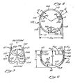
- FIGURE 1 shows a low profile pericardial xenograft heart valve 10 which comprises a valving element 20, a stent assembly 102 and a suture or sewing ring assembly 200.
- the coaptation stitches 130, 132 and 134 cause coaptation or joining of the edges of the tissue leaflets of valving element 20 in the vicinity of the tips of the stent legs thereby forming radial coaptation lines 133 in FIGURE 1.
- FIGURE 2 depicts an exploded view of the tissue valving element 20 prior to attachment of the stent 102, and generally shows the three stitch seams 22, 24 and 26 which join the three tissue leaflets 30, 50 and 70 into a right cylindrical valving element. This valving element is then sewn to the cloth-covered stent 102.
- FIGURE 16 depicts one of the leaflets, leaflet 30, of the valving element 20, as exemplary of all of the leaflets 30, 50 and 70, all of which are substantially identical.
- the leaflet 30 is a generally flat layer or sheet of pericardium tissue, treated as will be described and discussed in more detail hereinafter, and includes a curved bottom 32 and curved sides 34 and 36 with a top, or outflow edge generally indicated at 40.
- the top 40 comprises three distinct portions. Edges 42 and 44 converge upwardly like symmetrical sides of a triangle to a central plateau 46 at the top and form obtuse corners with the sides 34 and 36, respectively, on the bottom.
- Each of the leaflets 50 and 70 are to be understood as including corresponding elements, including the top or outflow edges 60 and 80, as shown in FIGURE 2, for example, and plateaus 66 and 86 corresponding to plateau 46.
- the three leaflets 30, 50 and 70 are in all essential respects identical, although there will be some minor variation in the exact shape and size of these leaflets because they are made from naturally occurring tissue and considerable manual dexterity and skill is required in production. Minor variations, so long as the function is not impaired, are readily tolerated in the present valve construction.
- the shape of the leaflets 30, 50 and 70 is very important to the proper functioning of the valve, although precise dimensions are not critical because minor deviations and dimensions can be compensated for in the final joinder of the leaflets into the valving element and in fitting the valving element over the stent.
- One portion of the configuration of the leaflets is of vital importance to the optimum functioning of the present invention, although the invention will function in an improved manner over the prior art even if very minor deviations are permitted.
- This important portion of the configuration is the truncated triangular top edge converging to the plateau 46 in FIGURE 16 and to plateaus 66 and 86 in the leaflets 50 and 70.
- the base of the triangle is, of course, an imaginary line joining the lower corners of the top edge.
- Plateau 46 is centrally located between the juncture of the outflow edge portion 42 with side 34 and outflow edge portion 44 with side 36.
- the best definition of the shape of this obtuse truncated triangle defined by the plateau 46 and the juncture of the top edges 42 and 44 with the sides of the leaflet, is that this truncated triangle is so configured and dimensioned that when the three leaflets are sewn together at their respective edges to form a cylinder, and fitted over a stent, with a coaptation stitch positioned directly over the end of the stent when the valve is closed, the plateau 46 of the leaflet 30 touches, or substantially touches, the corresponding plateaus 66 and 86 of the leaflets 50 and 70, with no more than about 1 mm of face-to-face contact, in the center of the flow path of the valve with substantial face-to-face contact, i.e.
- FIGURE 18 depicts the valve of FIGURE 1 cut perpendicular the radius defined by the cusp coaptation line 133, the area of.contact being .shown at 90.
- the maximum face-to-face contact is about halfway between the center and the legs and would be at least 2 or 3 mm but not more than 9 or 10 mm, optimally from 3 to 7 mm depending on valve size.
- leaflet 30 It is neither necessary nor possible to give exact shape and dimensional definitions to the leaflets exemplified by leaflet 30, but the configuration may be described, realizing that the truly critical relationship is the interrelationship of the three obtuse truncated triangular portions.
- the maximum width of the leaflet lies about midheight thereof.
- the height of the leaflet is, of course, of no criticality whatever, and so this is merely a general relationship.
- the sum of Sa, Sb and Sc (see FIGURE 16) is approximately equal to one-half of the total vertical height of the leaflet, Sa representing the mean altitude of the obtuse truncated triangle formed by plateau 46, converging edge portions 42 and 44 and the base defined by the junctures of top edge 40 with side 34 and side 36, respectively, Sb plus Sa being equal to about 35% plus or minus 3 to 5% of the total vertical height, and the sum of Sa, Sb and Sc being about 50% plus or minus around 10% of the total vertical height.
- the width of the leaflet, Wa, measured Sa down from the plateau 46 is about 85% plus or minus 10% of the maximum width, Wc, of the leaflet, Sa being around 12 to 17% of the total vertical height.
- the width Wb measured at Sa plus Sb from the plateau 46. is about 95% plus or minus about 5% of the maximum width.
- the exact width and height ratios depend generally upon the overall size of the valve and will usually fall within the ranges indicated, although the first definition by function is the best and most meaningful description presently comprehended.
- the valving member for the size 23 valve is a section of pericardium 0.012 inch thick, with a maximum height of 21 millimeters and a maximum width Wc of 26.5 millimeters at about 52% of total height.
- the width Wa of the obtuse triangle is 22.5 millimeters measured at Sa down about 14% of the total height from the top, the intermediate width Wb being 25.5 millimeters at Sb, 35% from the top. Again, this is merely one example of one size of a valve and the dimensions are not the critical factor; it is the interrelationship of the top edges of the leaflet that is critical.
- Glutaraldehyde has been used effectively to -stabilize connective tissue for clinical heart valve substitutes for several years.
- the tissue leaflets of the preesnt invention are cut from pericardium tissue, although other tissues may be used.
- formaldehyde and glutaraldehyde tanning in preservation of tissue is described by E. Aubrey Woodruff, The Chemistry and Biology of Aldehyde Treated Tissue Heart Valve Xenografts, in Ionescu, TISSUE HEART VALVES, Butterworths, 1979. Woodruff and other contributors to TISSUE HEART VALVES discuss in detail the glutaraldehyde tanning and preservation of connective tissue.
- the stent assembly refers generally to the entire stent assembly which includes a biologically compatible metal or plastic stent 102.
- the stent 102 defines the configuration of the stent assembly.
- the stent 102 may be considered as three one-third protions of a stent integrally formed of one piece of material although, of course, the method of formation or the number of pieces is of no consequence provided the completed stent is as described herein.
- the stent 102 comprises an annular base or ring 104 which extends around and defines the flow orifice of the valve. Coupled to the ring or integrally formed therewith are a plurality of stent legs extending upwardly a distance H toward the outflow end of the valve from the lowermost portion of the base.
- the bottom or inflow edge of the stent 102 is also scalloped to conform generally to the arc of the scallops between the legs. These bottom scallops generally follow the configuration of the scallops 112 of the outflow edge so as to generally form parallel edges defining ring or base 104.
- the scallops of the lower or inflow edge of the base and the scallops of the outflow edge between the legs vertically define three generally elliptical shaped one-third portions of the base between the centerlines of the respective upright legs which together circumferentially form a right cylinder of constant diameter having an inside diameter D with the legs extending parallel to the axis of the cylinder as shown in FIGURE 5.
- the stent assembly in the preferred embodiment, also includes a fabric covering which totally or at least substantially encloses-the stent 102. It is not essential to the functioning of the present valve that the stent be cloth-covered, but it has been long recognized that there are structural and biological advantages to the use of fully cloth-covered stents for supporting tissue valves. This concept predates the present invention and constitutes no part thereof but is simply adopted as part of the best mode in carrying out the present invention.
- the fabric covering described in detail by Ionescu et al in U.S. Patent 4,084,268 has been generally adopted, and the same techniques are applied in the present invention as are taught in U.S. Patent 4,084,268 except for the improvements disclosed herein. Reference is made to U.S.
- Patent 4,034,268 for specific details of the fabrics, knots, sewing and techniques, and the teachings of said patent are incorporated herein by reference. It is sufficient here to describe the stent assembly as including a cloth covering which encloses or substantially encloses and conforms to the stent.
- FIGURE 7 is a partial cross-section depicting a fabric 120 enclosing the outside of the stent, a fabric 122 which encloses the inside of the stent, with a suitable seam area 124 joining the fabrics along the top or outflow edge of the stent.
- a fabric 126 is joined along the lower edge of the stent and extends outwardly forming part of and attaching a sewing or suture ring generally indicated at 200 which may be of any of the forms used in the prior art.
- suture rings comprise a plurality of layers of fabric and padding, 202, 204 and 206, enclosed in layer 126, soft enough to permit the suturing needle to be readily inserted through it and yet rigid and strong enough to provide firm mounting of the prosthesis in the heart valve area.
- the suture ring 200 of this invention differs from the prior art suture rings only in that it curves and conforms to the scalloped contour of the valve ring or base defined by the portion 104 of the stent 102.
- tissue leaflets after being sewn to form a cylinder as shown in FIGURE 2, may be sewn to the stent assembly in any conventional manner, as, for example, by running stitches shown in 210 in FIGURE 7.
- FIGURE 7 depicts the valve in a partially completed configuration with the tissue leaflets 30 and 70 joined by seam 22, the upper edges 80 and 40 substantially touching or just touching, without a large or significant surface-to-surface contact of the two leaflets.
- Coaptation stitch 130 is disposed directly over the tip 109 of the stent leg 108 and passes through a hole 121 in the tab 123 to form the radial coaptation line 133.
- FIGURE 8' shows another stage in the construction of the valve shown in FIGURE 7 by the addition of the pledget and cover 220.
- This cover is sewn by stitches 222 to the stent leg through the tissue as described by Ionescu et al in U.S. Patent 4,084,268, or it can be connected in any other convenient manner.
- the fabric covering, the pledget, and the sewing, all as disclosed with great particularity by Ionescu et al, supra, are utilized in carrying out the invention in its preferred embodiment, but they are not part of the invention per se.
- Coaptation of the tissue leaflets is caused by the action of coaptation stiches 134, 130 and 132 shown in FIGURE 1.
- the present invention departs from the prior art in a very important and significant manner in the way in which the coaptation of the edges 40 and 60, the edges 40 and 80, as best shown in FIGURE 18, and the edges 60 and 80 abut in touching relationship.
- This coaptation is defined generally - by the placement of the coaptation stitches 134, 130 and 132 directly above the respective stent legs 106, 108 and 110, the placement of the coaptation stitch 130 being depicted as exemplary in FIGURES 7 and 8.
- prior art valves such as the one disclosed in U.S.
- FIGURE 9 illustrates a tissue valve in the fully open position.
- the legs be splayed outwardly from the base.
- the input diameter D in was smaller than the outflow diameter D out , D out out being the diameter of the circle in which the legs at the outflow end of the valve lie.
- the coaptation stitches of the prior art were formed inside the legs, and the diameter of the circle on which these coaptation stitches were made to lie was made, or attempted to be made, approximately equal to D in .
- the stent viewed circumferentially, e.g.
- the stent 102 of the present invention is, viewed circumferentially, a right cylinder, with the axis of the cylinder lying in the center of the flow path and the legs extending from the inflow end toward the outflow end (the top as viewed in the figures) of the valve parallel to the axis of the right cylinder.
- D in becomes equal to D o ut'
- the ratio U/D, D being equal, of course, to the inner diameter of the stent.
- the ratio of U/D in the present valve is between about .50 and about .65, and optimally from about .55 to .62.
- the valving element is a generally cylindrical tissue element, which has a profile of less than two-thirds the profile of prior art valves, which closes more rapidly than prior art valves of related construction, and in which the stresses in the cusps of related prior art valves have been wholly or substantially avoided.
- This new result comes about by reason of the interaction and cooperative action and function of the U/D ratio of the stent, the positioning of the coaptation stitch above the end of the stent leg, and the unique configuration of the cusp leaflets of the valving element.
- the flow path is substantially a right cylinder through the valve, with the coaptation stiches being placed directly above the legs.
- This has two functions. The first is of significance but, comparatively, of lesser significance than the other. The first result of this placement of the coaptation stitches is that a larger flow orifice is obtained without the necessity for splaying the legs of the valve. More importantly, the stresses of the prior art tissue valves at four o'clock and at eight o'clock, i.e. at the lower right and the lower left-hand portions of the cusp, when viewing the cusp straight on laterally, have been avoided without fluttering, rolling and floating of the edges of the tissue at the outflow end of the valve.
- valve element comprises three tissue leaflets joined to form a generally cylindrical valve element having three points which extend centrally of each of the cusps respectively toward the outflow end of the valve and centrally between the ends of the legs, the valve element forming in the open position a cylinder having three points on the outflow end thereof and, in the closed position, forming three cusps which arc inwardly between the legs with the outflow end of the leaflets touching with the three points adjacent each other in the center of the outflow end of the valve.
- leaflets While in the preferred embodiment they are formed of three separate pieces, they may very well be formed of a single integral piece of tissue with appropriate cutting and stitching such that the end result, the valving element, has the proper configuration. Thus, while it is convenient to start with three pieces of tissue, the same invention may be practiced with only one piece in which the three leaflets are integrally joined.
- the shortening of the implant depth, to less than about two-thirds of the prior art stent heights of corresponding valves, and the adoption of the coaptation stitch directly above the ends of the legs, permit the use of the above described valving element while providing a substantial area of face-to-face overlapping contact along the radial contact lines of the cusps and obviating the tendency of the outflow ends of the leaflets to roll, flutter, and otherwise to delay in closing or to twist and deform by minimizing the coaptation, at the center of the valve, of the plateaus 46, 66 and 86.
- FIGURE 3 shows the improved stent in perspective.
- FIGURE 5 shows a top view of the stent, and
- FIGURE 6 is a sectional view of the stent taken along section line 6-6 in FIGURE 5. It is advantageous to use this preferred stent design in conjunction with the valving element 20 described above. Such a combination is a preferred method of valve construction in the present invention.
- the preferred stent design may be employed with other valving elements, and, on the other hand, the valving element 20 may be used with other stents.
- the width W t of the stent legs 106, 108 and 110 at their tips 107, 109 and 111, as viewed in FIGURE 5, is substantially less than the width of the tips of prior art stent legs.
- the width W t is equal to the diameter of the half circle defining the tip if the tip is rounded. In other embodiments where the tip is not rounded, W is measured between the points near the tip where the edges of the stent leg first start to curve in toward the center line of the stent leg.
- the stent legs are rounded at their tips.
- the width of the stent legs at the tips thereof has been reduced from approximately 2.032 millimeters in prior stents to a substantially narrower range of widths from about 0.76 mm to about 1.14 mm.
- This reduced width of the stent legs at their tips has the effect of increasing the radius of curvature of the tissue inside the stent leg and tip. This curvature is caused by the action of the coaptation stitches 134, 130 and 132 in FIGURE 1 and by closure of the valve which causes collapse of the cusps 30, 50 and 70 toward the center of the valve under restriction of the coaptation stitches.
- tissue leaflets 30, 50 and 70 curve less sharply together at the tips 107, 109 and 111 of the stent legs when the tips of the legs are narrower. This increased radius of curvature translates into reduced stress in the tissue of the cusps and a longer service life for the valve.
- this reduced width of the tips of the stent legs 106, 108 and 110 in FIGURE 3 leaves less material in the stent legs to carry the structural loading of the closed leaflets caused by the impulse pressure in the flow of blood caused by intermittent pumping action of the heart.
- tabs 120, 123 and 125 are added at the outflow end or tip of each of the stent legs to add structural strenth to the legs. These tabs preferably project inwardly toward the center of the stent and are integrally formed with the stent legs and preferably conform to the width W T at the tips of the stent legs as seen in FIGURE 5. The tabs extend both vertically down the stent leg for a distance H tl , FIGURE 6, and toward the center of the aperture defined by the stent ring for a distance T - .
- the tabs 120, 123 and 125 have apertures 121 formed therein through which the coaptation stitches pass. It is preferred that the coaptation stiches be passed through the holes 121 in the tabs since this registers the position of the coaptation stitch at a positive, repeatable location.
- the diameter of the holes 121 in the preferred embodiment is 0.813 mm, and the dimension T t in FIGURE 6 is chosen to give sufficient strength.
- the use of holes 121 in the tabs located as described above insures good repeatability of manufacture because different assembly workers cannot change the orifice diameter or induce stresses in the tissue by inadvertent mislocation of the coaptation stitch too far toward or away from the center of the aperture.
- the tabs 120, 123 and 125 are included in the preferred embodiment because they have been found to be highly desirable and necessary, in many instances, for sufficient strength; however, the tabs are not always necessary. With refined manufacturing techniques and adaptation of stronger materials, the tabs are expected to be eliminated or reduced in size.
- the fundamental concept disclosed herein is extension of the service life of the valve by reducing stress levels in the tissue by, among other things, utilizing narrower, rounded stent leg tips 107, 109 and 111 as shown in FIGURES 3 and 4. Ideally, a substantially zero tip width would be desirable, but structurally this is impossible at present.
- the width of the stent leg at its tip is made more narrow than heretofore known; however, the stated width of the tips of the stent legs in the preferred embodiment should not be understood as limiting the invention in any way.
- a general guideline for the narrowness of the stent leg tip is that the tip should be sufficiently narrow so that the quotient of the radius of curvature of tissue together inside the stent leg tip divided by the thickness of the tissue is greater than or equal to five.
- the radius of curvature R of the tissue inside a typical stent leg tip is illustrated in FIGURE 4. This curvature is caused by the coaptation of the leaflets under pressure and tends to concentrate shear stresses in the tissue at points 135 and 137 where curvature is greatest. In the preferred embodiment, this ratio should be a minimum of approximately five.
- FIGURES 4 and 10 This curvature at two of the various places on the stent where it occurs is illustrated in FIGURES 4 and 10.
- FIGURE 4 is a sectional view taken along section line 4-4 in FIGURE 2 looking down on the top of the stent leg. The center of the stent is toward the top of FIGURE 4.
- the radius lines R illustrate the radius of curvature of the tissue 21 together inside the stent leg tip 107 and the fabric covering 113 surrounding the tip.
- the coaptation stitch 134 is seen to pass through the hole 121 in the stent leg tip and is approximately centered above the tip of the leg.
- the points of maximum curvature 135 and 137 are seen to be in the tissue at a point just inside of the centermost extremity of the cloth covering 113.
- the thickness of the tissue is designated as T.
- the ratio of R c /T should be greater than or equal to five for extended durability.
- FIGURE 10 is another sectional view of a place of curvature of the tissue around the stent taken along section line 10-10 in FIGURE 2.
- R indicates the radius of curvature of the tissue 21 over the top of the cloth covering 124 surrounding the base ring 104 of the stent.
- T indicates the thickness of the tissue and, for extended durability, the ratio R c/ T should be greater than or equal to five.
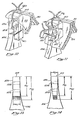
- FIGURE 11 there is shown another embodiment of a coaptation stitch arrangement typical for all three stent legs.
- This embodiment includes a separate coaptation stitch 134 passing through the tissue leaflets 50 and 70, through the top hole 121a in the tab 120, and up and over the tip 107 of the stent leg 106.
- Coaptation stitch 134 could be a group of stitches.
- Another coaptation stitch 135, or group of stitches passes through the tissue leaflets 50 and 70, through the bottom hole 121b in the tab 120, and out and around the outside edge 138 of the stent leg 106.
- the top coaptation stitch 134 lies in a plane parallel to the long axis of the stent leg 106.
- the top stitch 134 or group of stitches is tied off above the tip 107 of the stent leg.
- the bottom coaptation stitch 135 lies in a plane generally perpendicular to the plane of the top stitch or stitches 134 and is tied off at the outside edge 138 of the stent leg 106. These stitches are placed so that they do not interfere with the normal operation of the valve in the open position.
- the thread of coaptation stitches 134 and 135 will pull to the side of the holes 121 closest to the stitch knot when the thread is pulled tight.
- the thread may be passed through the tissue leaflets along an axis not parallel to the axis of the bottom hole 121b.
- the tissue leaflet on one side of the hole is moved farther toward the knot at the outside edge 138 of the stent leg 106 than is the tissue leaflet on the other side.
- uneven pulling can cause wrinkling of the tissue leaflets.
- FIGURE 12 shows the preferred embodiment of the coaptation stitching arrangement.
- FIGURE 12 shows a coaptation stitch or stitches 140 residing generally in a plane parallel to the long axis of the stent leg 106 and passing through both the top and bottom holes 121a and 121b and through the tissue leaflets 50 and 70.
- the stitch can be either a single figure eight stitch as shown in FIGURE 12 or it can be two separate stitches, each passing through both tissue leaflets and through one of the holes 121a or 121b.
- Each stitch 140 is tied together above the tip 107 of the stent leg 106.
- the figure eight stitch shown in FIGURE 12 is the preferred embodiment, however, because it is simpler and faster to implement than two separate stitches both in a vertical plane. The figure eight stitch is simpler because only one knot need be tied.
- the coaptation stitch illustrated in FIGURE 12 tends to eliminate the tendency for variations in stitch placement during manufacturing which can cause wrinkling of the tissue leaflets.
- the width, W T, of the tab and the amount of inward projection or protuberance, P, of the tab from the inside edge of the hole toward the center of the flow aperture of the valve is important in preventing abrasion of the tissue leaflets on the inside edges of the tab.
- the tissue leaflets coapt together during the closing action of the valve, if the tabs 120, 123 and 125 protrude too far in toward the center of the flow aperture, abrasion can occur in the area generally marked 142 in FIGURE 8.
- the dimension P shown in FIGURES 5 and 12 is, in the preferred embodiment, restricted to a maximum of forty thousandths of an inch (0.040 inches or 1.016 millimeters).
- any embodiment will be satisfactory wherein the distance which the tab extends toward the center of the aperture is restricted to a distance which substantially eliminates touching between the tissue leaflets and the bottom surfaces or lower 20% of the tab under maximum backpressure conditions.
- the bottom of the tab surfaces refers generally to those portions of the tab surfaces below the midway point in the height of the tab designated H T2 in FIGURES 6, 13 and 14.
- the area of coaptation of the tissue leaflets tends to grow larger during higher backpressure conditions. This phenomenon can be visualized in placing the fingertips on each hand together fingerprint to fingerprint with the fingertips on the other hand to form a roof shaped arrangement.
- the fingerprint area of contact represents the area of coaptation 144 in FIGURE 8. As the hands are pressed together keeping the fingers stiff, the fingers tend to flex toward each other such that the opposing first and second knuckle areas tend to come closer together. This represents the situation when higher backpressure exists on the tissue leaflets during closing.
- the area of contact between the leaflets tends to increase by expanding in the downward direction, i.e. toward the stent ring 104 in FIGURE 7. If the tabs 120, 123 and 125 extend too far in toward the center, abrasion between the mobile areas of the tissue leaflets just inside the tabs and the bottom portions of the tabs can occur. Restriction of the distance which the tabs protrude into the flow aperture tends to eliminate the aforestated abrasion.
- FIGURE 13 there is shown a detail view of the preferred embodiment for the tabs and stent leg tips.
- the width, W T' of the tab 120 remains constant throughout its height, H T2' regardless of the width of the stent leg 106. It is seen in FIGURE 13 that the width of the stent leg 106 is increasing at points farther away from the tip 107.
- FIGURE 14 shows another embodiment for the tabs wherein the width, W T , of the tab 120 decreases at points farther down from the tip 107 irrespective of the width of said stent leg.
- the purpose of maintaining a constant or decreasing width for the tabs 120, 123 and 125 is to minimize the possibility of abrasion of the tissue leaflets on the tabs during closure of the valve and coaptation of the tissue leaflets just inside the tabs.
- the increasing width of the stent legs 106, 108 and 110 tend to give shape and support to the tissue leaflets to form the cusps of the valve.
- the increasing width of the stent legs versus the constant or decreasing width of the tabs tends to keep the tissue leaflets away from the lower surfaces of the tabs during coaptation thereby minimizing abrasion. Any shape or form for the tabs which accomplishes the purpose of minimizing or eliminating this abrasion will be satisfactory and is intended to be included within the scope of the claims appended thereto.
- optimum stent dimensions for the stent depicted in FIGURES 5 and 6 are given in Table I.
- D refers to the inside diameter of the stent ring and D refers to the outside diameter thereof.
- U refers to the depth of scallop 112 and W refers to the width of stent ring 104.
- R i refers to the inside radius of the scallop 112 and R o refers to the outside radius of the scallop forming the bottom of stent ring 104.
- HT2 refers to the total height of the tabs.
- the stent may be made of titanium, Delrin (TM), polyacetal, polypropylene or Elgiloy with the fabric covering of Dacron or Teflon but the invention is not limited to these materials nor is it limited to any particular covered stent; indeed, the present invention can be carried out without a covered stent.
- TM Delrin
- the structures and elements of the invention have been described, in their best . mode embodiments, as integral, in the case of the stent, and separate, in the case of the leaflets.
Abstract
Description
- The early development of prosthetic heart valves is well documented in papers given at symposia in 1960 and in 1968, published in PROSTHETIC HEART VALVES, Lyman A. Brewer III, Ed., Charles C. Thomas Publishing Co., Springfiled, Illinois (1969), Second National Conference on Prosthetic Heart Valves; PROSTHETIC VALVES FOR CARDIAC SURGERY, K. Alvin Merendino, Ed., Charles C. Thomas Publishing Co., Springfield, Illinois (1961).
- Lefrak and Starr recently surveyed the development of cardiac valve prostheses, E.A. Lefrak and A. Starr, CARDIAC VALVE PROSTHESES, Appleton-Century-Krofts, New York, 1979 and the development of tissue heart valves has been comprehensively reviewed by Ionescu, Marian I., TISSUE HEART VALVES, Butterworths, Boston, 1979.
- Great efforts have been expended in the development of tissue heart valve prostheses and in the development of supportive structures, or stents, for tissue valves. Representative of effots to develop stents for tissue valves are the disclosures in the following United States patents: Patent 3,570,014, W. D. Hancock, March 16, 1971; Patent 3,714,671, William Sterling Edwards et al, February 6, 1973; Patent 3,755,823, W. D. Hancock, September 4, 1973; Patent 3,983,581, William W. Angell, October 5, 1976; Patent 4,035,849, William W. Angell et al, July 19, 1977; Patent 4,079,468, Domingo Santo Liotta, March 21, 1978; Patent 4,084,268, Marian I. Ionescu et al., April 18, 1978; Patent 4,106,129, Alain F. Carpentier et al, August 15, 1978; Patent 4,172,295, Richard J. Batten, October 30, 1979 and Patent 4,192,020, Richard B. Davis et al, March 11, 1980. Other structures are also reported in the aforementioned treatises on heart valve developments.
- A number of specific tissue valves are described in the following publications:
- W. Sterling Edwards et al, MITRAL AND AORTIC VALVE REPLACEMENT WITH FASCIA LATA ON A FRAME, Journal of Thoracic & Cardiovascular Surgery, Volume 58, No. 6, December 1969, Pages 854-858; Ionescu, M.I. et al, HEART VALVE REPLACEMENT WITH IONESCU-SHILEY PERICARDIAL XENOGRAFT, Cardiology Digest, June 1977, Page 45; Ionescu, M.I. et al, HEART VALVE REPLACEMENT WITH THE IONESCU-SHILEY PERICARDIAL XENOGRAFT, The Journal of Thoracic and Cardiovascular Surgery, Volume 73, Pages 31 - 42, 1977; Tandon, A. P. et al, LONG-TERM HAEMODYNAMIC EVALUATION OF AORTIC PERICARDIAL XENOGRAFT, British Heart Journal,
Volume 40, Pages 602-607, 1978; Ionescu, M.I. et al, LONG-TERM CLINICAL AND HAEMODYNAMIC EVALUATION OF THE IONESCU-SHILEY PERICARDIAL XENOGRAFT HEART VALVE, Thoraxahirugie,Volume 26, Pages 250-258, 1978; Ionescu, M. I. et al, LONG-TERM SEQUENTIAL HEMODYNAMIC EVALUATION OF RIGHT VENTRICULAR OUTFLOW TRACT RECONSTRUCTION USING A VALVE MECHANISM, The Annals of Thoracic Surgery, Volume 27, No. 5, May 1979; Ross, D. N., FLEXIBLE BIOPROSTHETIC PERICARDIAL HEART VALVE, Thoracic & Cardiovascular Surgery, Volume 28, Pages 150-152, 1980. - Particular techniques for preparing, handling and storing tissue valves are disclosed in U.S. Patents Nos. 3,966,401, Hancock et al, June 29, 1976, and 4,182,446, Penny, January 1980.
- Some of the earliest heart valve prostheses were flexible two-or three-cusp valves in which the cusps were constructed of various types of fabric. Some of these flexible leaflet valves had good flow characteristics but most failed early. The leaflets tore, separated from the annulus, or become rigid due to fibrous tissue ingrowth. From about 1960 into the 1970's the trend was to mechanical valves. These ranged from the mecahnically quite simple Starr-Edwards valve to the relatively sophisticated Bjork-Shiley valve and included a number of disc poppet valves. These mechanical valves generally dominated the market and are still very satisfactory for many applications. Tissue valves are however the preferred treatment where anticoagulation therapy is not tolerated by the patient.
- In 1962, Donald Ross and Sir Brian Barratt-Boyes, working independently, were performing implanatations of homograft tissue valves, some of which were free graft implants and some of which were mounted on supporting stents. Fully clothed covered rigid stents were used in some of these homograft valves.
- In 1965, Drs. Binet and Carpentier, and their associates, implanted a specially prepared porcine aortic valve xenograft. These porcine valves were sterilized and treated, e.g. with formaldehyde, and were commonly attached to a metal stent. Experience showed that these valves were of short life, largely because formaldehyde was used as the cross-linking agent. Formaldehyde was found to create reversible cross links in the tissue, thereby allowing early breakdown of the tissue. Dr. Carpentier, in about 1968, established the concept of the bioprosthesis by substantially eliminating antigenicity of the tissue, principally by changing the preservative from formaldehyde to glutaraldehyde. Glutaraldehyde has been shown to create cross links of a more permanent nature than those created by formaldehyde.
- A number of porcine bioprostheses and specially designed stents for supporting these prostheses resulted from the efforts of Warren Hancock et al. Generally, pig aortic valves are procured under clean conditions, placed in a cold, balanced electrolyte solution, excess tissue is trimmed and the xenografts are immersed in 0.2% glutaraldehyde. The leaflets are held in their normal valving position under pressure during the tanning process and each valve is sutured to a cloth covered stent by sutures. A number of designs and stent constructions for the Hancock type valve are exemplified in the aforementioned United States Patents Nos. 3,570,014 and 3,755,823. Stents for porcine valves were developed by a number of other workers also, see, e.g., U.S. Patents Nos. 3,983,581; 4,035,849; 4,079,468 and 4,106,129.
- Stents for supporting cusp valves of other tissue members, e.g. fascia lata and pericardium, have been developed by a number of workers, see, e.g., U.S. Patent 3,714,671, and Edwards et al, MITRAL AND AORTIC VALVE REPLACEMENT WITH FASCIA LATA ON A FRAME, supra. Much of the pioneering work in this area of valve development was done by Dr. Martin I. Ionescu and his associates, see, e.g., Bartek et al, FRAME-MOUNTED TISSUE HEART VALVES: TECHNIQUE OF CONSTRUCTION, Thorax, Volume 29, Pages 51-55, 1974; Ionescu et al, HEART VALVE REPLACEMENT WITH IONESCU-SHILEY PERICARDIAL XENOGRAFT, Cardiology Digest, June 1977; Ionescu et al, HEART VALVE REPLACEMENT WITH IONESCU-SHILEY PERICARDIAL XENOGRAFT, The Journal of Thoracic and Cardiovascular Surgery, Volume 73, Pages 31-42, 1977; Tandon et al, LONG-TERM HAEMODYNAMIC EVALUATION OF AORTIC PERICARDIAL XENOGRAFT, British Heart Journal,
Volume 40, Pages 602-607, 1978; Ionescu et al, LONG-TERM CLINICAL AND HAEMODYNAMIC EVALUATION OF THE IONESCU-SHILEY PERICARDIAL XENOGRAFT HEART VALVE, Thoraxchirugie,Volume 26, Pages 250-258, 1978; Ionescu, et al, LONG-TERM SEQUENTIAL HEMODYNAMIC EVALUATION OF RIGHT VENTRICULAR OUTFLOW TRACT RECONSTRUCTION USING A VALVE MECHANISM, The Annals of Thoracic Surgery, 27, 425-434, 1979; and Ionescu, Editor, TISSUE HEART VALVES, Butterworths, 1979. - A number of improvements in the basic Ionescu tissue heart valve have been made. For example, a tissue heart valve has been developed which has a cloth-covered stent of special construction, in which the outflow annulus diameter of the valve is defined and limited by the positioning of a coaptation stitch on the inside of the supporting legs of the stent, as has been the practice since the early development of the Ionescu type tissue heart valve. Another improvement in the method for aligning the tissue of the cusps of the Ionescu type heart valve is described in U.S. Patent No. 4,172,295, which also discloses the coaptation stitch inside the stent legs. It has been the practice, in order to achieve a maximum flow orifice in valves of implantation diameters less than or equal to 23 mm, to splay the stent legs outwardly in an effort to achieve a full-flow orifice inside the coaptation stitches.
- While these various modifications and improvements in the basic Ionescu valve over the years have solved some of the problems, there remains a number of problems which have not been solved. Among these problems are the limitations on the size of the flow annulus which can be obtained, with consequent increased pressure gradient across the valve. Perhaps the most important disadvantage of the three-cusp tissue valves of the prior art is the fact that in each cusp there are two points of stress due to three-dimensional flexure at about 4 o'clock and at about 8 o'clock in the lower arc of the cusp, i.e. in the lower right hand portion and the lower left hand portion of the closed cusp as viewed laterally, head-on, from the outside. A similar phenomena is created by creases which tend to concentrate stress in the areas of the crease.
- The tissue valves of the prior art generally have relied upon a face-to-face meeting of the cusps in the closed position and, consequently, have required relatively high stent legs and, in general, the tissue valves of the prior art have trimmed the tissue around the outflow end so as to form a generally round regular cylindrical configuration. This approach has resulted in the concentration of stresses in fold areas or in the lower right and left hand portions of the cusps.
- An additional potential problem is that stress is concentrated in the tissue in some areas where sharp bending of the tissue around the stent occurs. Some measures can be taken to relive this stress. The stress tends to be highest at points of maximum curvature such as around the tips of the stent legs because of the pinching of the tissue leaflets together inside and above the tip of the stent leg.
- The problems described above are largely or entirely solved by the present invention.
- The present invention comprises an improved tissue valve prosthesis of the Ionescu type. The improved prosthetic heart valve of this invention comprises a stent which includes an annular base integrally formed with three legs which extend upwardly to the outflow ends of the legs. The space between the legs is configured to form generally elliptically shaped scallops having a depth U measured from the top of the legs to the bottom of the scallop. The stent, circumferentially, forms a right cylinder having a uniform interior diameter D, the legs extending parallel to the axis of the right cylinder. The lower edge of the stent forms scallops which correspond generally to the arc of the scallops between the legs. The scallops of the lower edge of the base and the scallops between the legs vertically define three generally elliptically shaped one-third portions of the base between their respective upright legs. A fabric covering totally encompasses and follows the configuration of the stent and an annular sewing ring is attached to the fabric covering and extends outwardly from the base. A tissue valve element is formed of three tissue leaflets, joined to form a generally cylindrical three-cusp valving element, each of the leaflets having a top edge forming a truncated triangle with a central high plateau tapering down on each side of the plateau to the corners adjacent the sides of the leaflet, giving the top of each leaflet a generally very obtuse, flat topped generally truncated triangular configuration. Conventional stitching or other means are utilized to attach the tissue valve element around the fabric covered stent to the fabric, around the annulus formed by the stent and up the outside surface of the fabric covered stent legs. A coaptation stitch through the tissue leaflets adjacent the upper edge thereof, and disposed directly above the top of the fabric covered stent, fixes the leaflets in position to form three cusps each having an upwardly extending point, extending in the outflow direction, midway between the legs. The upper edges, or outflow edges, of the cusps meet, in the closed position of the valve, with the points adjacent each other. In the open position, the tissue valve element forms a cylinder having an inside diameter at the top of the valve substantially equal to the inside diameter of the fabric covered stent, the flow path through the valve generally being in the configuration of a right cylinder with the axis of the cylinder corresponding to the flow axis of the valve, the legs and the stent forming a circumferentially right cylindrical surface around the axis, with the suture or sewing ring forming an annulus around the stent.
- For convenience, in describing the valve, the outflow end of the valve is depicted at the top of the drawings and the valve is described in this configuration; thus, the upward or top portion of the valve would correspond to the outflow portion of the valve and the bottom would correspond to the inflow end of the valve.
- In the prosthetic valve of this invention, the scallp depth U of the stent is between 50% and 65% of the stent inner diameter D. Optimally, the stent scallop depth U is from about 55% to about 62% of the diameter D. This U/D ratio is very important in providing a low profile tissue valve prosthesis which has optimum flexure and coaptation of the leaflets using tissue fixed in the unstressed state, and resultant maximum valve life.
- The outflow end of the three cusps of the valving member are, in the closed position, adjacent in the center and in face-to-face contact with each other along radii defined by the legs. The upper or outflow ends of the valving element lie in substantially face-to-face contact between the interior faces of the cusps of the valving element by from 0 to 1 or 2 mm in the center and from 3 to 7 mm intermediate the center and the legs, along the radial contact lines.
- A significant additional feature of the present invention resides in the preferred configuration of the stent legs wherein the ratio defined as the value of the radius of curvature of tissue around the inside top of said leg measured at the point of greatest curvature divided by the thickness of the tissue is approximately five or more. The width of the post top is approximately from 0.760 to 1.05 millimeters and the thickness of the cloth covered post top is approximately 2 millimeters. The tissue thickness in the preferred embodiment is approximately 0.3 millimeters. The tissue does not pinch together inside such narrow posts during closure at physiological pressure and an inside radius of curvature equal to or greater than 1.5 millimeters is obtained. The life of a valve using such a stent will be extended beyond that of a valve with a smaller radius of curvature.
- The improved stent is also designed so that the ratio of the radius of curvature of the tissue around the fabric-covered stent at a point between the upright stent legs divided by the thickness of the tissue is greater than or equal to five.
- Additional strength to the legs is provided by inwardly projecting tabs which are, preferably, integrally formed at the tips of the legs, conforming to the width of the stent legs at their tips but narrower than the stent legs at the bottom of the tabs, said tabs extending both vertically down the leg for a predetermined distance and inwardly toward the center axis of the stent. Apertures are formed in the tabs through which the coaptation stitches pass to register the coaptation stitch directly above the stent leg.
- The coaptation stitches can be in either of two embodiments. The first embodiment consists of two separate stitches, one passing through one aperture in the tab and defining a plane generally parallel to the long axis of the stent legs and tied off above the tips of the stent legs, and the other stitch passing through another aperture in the tabs and defining a plane which is generally perpendicular to the plane defined by the first stitch, said second stitch being tied off at the outside edge of the stent leg. The second embodiment of the coaptation stitch is a single stitch passing through a plurality of holes in the tabs which defines a plane which is parallel to the long axis of the stent leg. The second embodiment is the preferred embodiment and generally defines a figure eight pattern through a pair of holes in each tab.
- The inward projection of the tabs toward the center of the flow aperture of the valve is also limited to prevent touching between the tissue leaflets and the bottom of the tabs. Generally this distance of inward projection is limited to forth thousandths of an inch in the naked stent, i.e., no more than forty thousandths inward projection of the bare plastic tab. The width of the tabs is also limited to aid in preventing the bottoms of the tabs from touching the tissue leaflets. In the preferred embodiment, the widths of the tabs remains constant throughout their length while the widths of the stent legs increases at points farther from the tips of the stent legs. In another embodiment, the widths of the tabs decrease at points further from the tips of the stent legs irrespective of the widths of the stent legs.
-
- FIGURE 1 is a perspective view of a completd valve of this invention.
- FIGURE 2 is an exploded view of the cloth covered stent and the valving element formed of three leaflets prior to attachment to the stent.
- FIGURE 3 is a perspective view of the preferred stent configuration.
- FIGURE 4 is a sectional view of the curvature of tissue around the covered stent leg taken along line 4-4 in FIGURE 2.
- FIGURE 5 is a top view of the stent shown in perspective in FIGURE 3.
- FIGURE 6 is a sectional view taken along section line 6-6 in FIGURE 5.
- FIGURE 7 is a partial perspective view of the coaptation of the tissue leaflets with the stent leg and coaptation stitch.
- FIGURE 8 is another partial perspective view showing the view of FIGURE 7 in a later stage of manufacture.
- FIGURE 9 is a top plan view, viewed from the outflow end, of the completed valve in the fully open position.
- FIGURE 10 is a sectional view of the curvature of tissue around the stent taken along section line 10-10 in FIGURE 2.
- FIGURE 11 is a detailed view of an embodiment of the coaptation stitching.
- FIGURE 12 is a detailed view of the preferred embodiment of the coaptation stitching.
- FIGURE 13 is a detailed view of a typical tab and stent leg tip showing the relative widths of each.
- FIGURE 14 is a detailed view of another embodiment of a typical tab and stent leg tip showing the relative widths of each.
- FIGURE 15 is a top view and a sectional view, taken along the section line in the top view, of a prior art stent utilized in one of the improvements of the basic Ionescu valve, with the measurements thereof shown for purposes of comparison with the present invention.
- FIGURE 16 is a flat plan view of the outline of one of the leaflets used in the present valving element, before the sewing of three such leaflets together to form a cylindrical valving member.
- FIGURE 17 is a top plan view, viewed from the outflow end, of the completed valve in the fully closed position.
- FIGURE 18 is a partial cross-section taken along line 18-18 in FIGURE 8 showing the closed cusps of the valve leaflets along the closure line.
- FIGURE 1 shows a low profile pericardial
xenograft heart valve 10 which comprises avalving element 20, astent assembly 102 and a suture orsewing ring assembly 200. The coaptation stitches 130, 132 and 134 cause coaptation or joining of the edges of the tissue leaflets ofvalving element 20 in the vicinity of the tips of the stent legs thereby formingradial coaptation lines 133 in FIGURE 1. - FIGURE 2 depicts an exploded view of the
tissue valving element 20 prior to attachment of thestent 102, and generally shows the threestitch seams tissue leaflets stent 102. - FIGURE 16 depicts one of the leaflets,
leaflet 30, of thevalving element 20, as exemplary of all of theleaflets leaflet 30 is a generally flat layer or sheet of pericardium tissue, treated as will be described and discussed in more detail hereinafter, and includes a curved bottom 32 andcurved sides Edges central plateau 46 at the top and form obtuse corners with thesides leaflets leaflets - The shape of the
leaflets plateau 46 in FIGURE 16 and toplateaus leaflets Plateau 46 is centrally located between the juncture of theoutflow edge portion 42 withside 34 andoutflow edge portion 44 withside 36. The best definition of the shape of this obtuse truncated triangle defined by theplateau 46 and the juncture of thetop edges plateau 46 of theleaflet 30 touches, or substantially touches, the correspondingplateaus leaflets plateaus cusp coaptation line 133, the area of.contact being .shown at 90. The maximum face-to-face contact is about halfway between the center and the legs and would be at least 2 or 3 mm but not more than 9 or 10 mm, optimally from 3 to 7 mm depending on valve size. - It is neither necessary nor possible to give exact shape and dimensional definitions to the leaflets exemplified by
leaflet 30, but the configuration may be described, realizing that the truly critical relationship is the interrelationship of the three obtuse truncated triangular portions. - The maximum width of the leaflet lies about midheight thereof. The height of the leaflet is, of course, of no criticality whatever, and so this is merely a general relationship. Thus, the sum of Sa, Sb and Sc (see FIGURE 16) is approximately equal to one-half of the total vertical height of the leaflet, Sa representing the mean altitude of the obtuse truncated triangle formed by
plateau 46, convergingedge portions top edge 40 withside 34 andside 36, respectively, Sb plus Sa being equal to about 35% plus or minus 3 to 5% of the total vertical height, and the sum of Sa, Sb and Sc being about 50% plus or minus around 10% of the total vertical height. The width of the leaflet, Wa, measured Sa down from theplateau 46 is about 85% plus or minus 10% of the maximum width, Wc, of the leaflet, Sa being around 12 to 17% of the total vertical height. The width Wb measured at Sa plus Sb from the plateau 46.is about 95% plus or minus about 5% of the maximum width. The exact width and height ratios depend generally upon the overall size of the valve and will usually fall within the ranges indicated, although the first definition by function is the best and most meaningful description presently comprehended. In a specific embodiment, the valving member for the size 23 valve is a section of pericardium 0.012 inch thick, with a maximum height of 21 millimeters and a maximum width Wc of 26.5 millimeters at about 52% of total height. The width Wa of the obtuse triangle is 22.5 millimeters measured at Sa down about 14% of the total height from the top, the intermediate width Wb being 25.5 millimeters at Sb, 35% from the top. Again, this is merely one example of one size of a valve and the dimensions are not the critical factor; it is the interrelationship of the top edges of the leaflet that is critical. - Glutaraldehyde has been used effectively to -stabilize connective tissue for clinical heart valve substitutes for several years. The tissue leaflets of the preesnt invention are cut from pericardium tissue, although other tissues may be used. The use of formaldehyde and glutaraldehyde tanning in preservation of tissue is described by E. Aubrey Woodruff, The Chemistry and Biology of Aldehyde Treated Tissue Heart Valve Xenografts, in Ionescu, TISSUE HEART VALVES, Butterworths, 1979. Woodruff and other contributors to TISSUE HEART VALVES discuss in detail the glutaraldehyde tanning and preservation of connective tissue.
- This disclosure is incorporated herein by reference. In the preferred embodiment of the present invention, percardium treated with .5% glutaraldehyde at pH 7.4 without fixing the tissue in a prestressed condition is preferred; however, it is to be understood that the invention disclosed and claimed here relates to the configuration of the valving leaflets and element and the supporting stent, and any suitably preserved tissue may be utilized in the present invention.
- The stent assembly refers generally to the entire stent assembly which includes a biologically compatible metal or
plastic stent 102. Thestent 102 defines the configuration of the stent assembly. Thestent 102 may be considered as three one-third protions of a stent integrally formed of one piece of material although, of course, the method of formation or the number of pieces is of no consequence provided the completed stent is as described herein. Thestent 102 comprises an annular base orring 104 which extends around and defines the flow orifice of the valve. Coupled to the ring or integrally formed therewith are a plurality of stent legs extending upwardly a distance H toward the outflow end of the valve from the lowermost portion of the base. There are three substantiallyidentical legs scallops 112 as best shown in FIGURE 3. The bottom or inflow edge of thestent 102 is also scalloped to conform generally to the arc of the scallops between the legs. These bottom scallops generally follow the configuration of thescallops 112 of the outflow edge so as to generally form parallel edges defining ring orbase 104. The scallops of the lower or inflow edge of the base and the scallops of the outflow edge between the legs vertically define three generally elliptical shaped one-third portions of the base between the centerlines of the respective upright legs which together circumferentially form a right cylinder of constant diameter having an inside diameter D with the legs extending parallel to the axis of the cylinder as shown in FIGURE 5. - The stent assembly, in the preferred embodiment, also includes a fabric covering which totally or at least substantially encloses-the
stent 102. It is not essential to the functioning of the present valve that the stent be cloth-covered, but it has been long recognized that there are structural and biological advantages to the use of fully cloth-covered stents for supporting tissue valves. This concept predates the present invention and constitutes no part thereof but is simply adopted as part of the best mode in carrying out the present invention. The fabric covering described in detail by Ionescu et al in U.S. Patent 4,084,268 has been generally adopted, and the same techniques are applied in the present invention as are taught in U.S. Patent 4,084,268 except for the improvements disclosed herein. Reference is made to U.S. Patent 4,034,268 for specific details of the fabrics, knots, sewing and techniques, and the teachings of said patent are incorporated herein by reference. It is sufficient here to describe the stent assembly as including a cloth covering which encloses or substantially encloses and conforms to the stent. - FIGURE 7 is a partial cross-section depicting a
fabric 120 enclosing the outside of the stent, afabric 122 which encloses the inside of the stent, with asuitable seam area 124 joining the fabrics along the top or outflow edge of the stent. Afabric 126 is joined along the lower edge of the stent and extends outwardly forming part of and attaching a sewing or suture ring generally indicated at 200 which may be of any of the forms used in the prior art. - Generally, such suture rings comprise a plurality of layers of fabric and padding, 202, 204 and 206, enclosed in
layer 126, soft enough to permit the suturing needle to be readily inserted through it and yet rigid and strong enough to provide firm mounting of the prosthesis in the heart valve area. Thesuture ring 200 of this invention differs from the prior art suture rings only in that it curves and conforms to the scalloped contour of the valve ring or base defined by theportion 104 of thestent 102. - The tissue leaflets, after being sewn to form a cylinder as shown in FIGURE 2, may be sewn to the stent assembly in any conventional manner, as, for example, by running stitches shown in 210 in FIGURE 7.
- FIGURE 7 depicts the valve in a partially completed configuration with the
tissue leaflets seam 22, theupper edges Coaptation stitch 130 is disposed directly over thetip 109 of thestent leg 108 and passes through ahole 121 in thetab 123 to form theradial coaptation line 133. - FIGURE 8'shows another stage in the construction of the valve shown in FIGURE 7 by the addition of the pledget and cover 220. This cover is sewn by
stitches 222 to the stent leg through the tissue as described by Ionescu et al in U.S. Patent 4,084,268, or it can be connected in any other convenient manner. The fabric covering, the pledget, and the sewing, all as disclosed with great particularity by Ionescu et al, supra, are utilized in carrying out the invention in its preferred embodiment, but they are not part of the invention per se. - Coaptation of the tissue leaflets is caused by the action of coaptation stiches 134, 130 and 132 shown in FIGURE 1. The present invention departs from the prior art in a very important and significant manner in the way in which the coaptation of the
edges edges edges respective stent legs coaptation stitch 130 being depicted as exemplary in FIGURES 7 and 8. In prior art valves such as the one disclosed in U.S. Patent 4,084,268, the coaptation stitch had been placed inside the circumference of the circle defined by the tips of the stent legs. Placement of the coaptation stitch directly above the tips of the stent legs tends to allow the orifice diameter of the fully open valve to equal the inside diameter of the covered stent. FIGURE 9 illustrates a tissue valve in the fully open position. - Another extremely significant departure from the prior art is the relative height H of the
stent 102, the depth U of the scallops between the legs of thestent 102, and the inside diameter D of the stent. - In the prior art it was considered necessary, or at least very important, that in smaller valve sizes, e.g. 23 mm or less, the legs be splayed outwardly from the base. Thus, referring to FIGURE 15, in the prior art stent 102', the input diameter Din was smaller than the outflow diameter D out, Dout out being the diameter of the circle in which the legs at the outflow end of the valve lie. The coaptation stitches of the prior art were formed inside the legs, and the diameter of the circle on which these coaptation stitches were made to lie was made, or attempted to be made, approximately equal to Din. Thus, the stent, viewed circumferentially, e.g. from the end, was not a right cylinder, but was generally frustoconical because of the splaying. Sometimes, of course, the splaying of the legs was accomplished by bending the legs out from another wide cylindrical base, but the result was substantially the same as a frustoconical imaginary figure derived from the diameter of the inflow and the outflow ends of the valve.
- In contrast to the prior art, the
stent 102 of the present invention is, viewed circumferentially, a right cylinder, with the axis of the cylinder lying in the center of the flow path and the legs extending from the inflow end toward the outflow end (the top as viewed in the figures) of the valve parallel to the axis of the right cylinder. Thus, Din becomes equal to D out' - Also of great significance is the ratio U/D, D being equal, of course, to the inner diameter of the stent. As compared with what is regarded as the closest and most pertinent prior art, the Ionescu type valve described by Ionescu et al in U.S. Patent 4,084,268, various features of which are also described in U.S. Patent No. 4,172,295 to Batten, the scallop depth U measured from the scallop bottom on the outflow edge of the
stent base 104 to the upper or outflow end of the stent legs (see FIGURE 6), is very much less, for a given valve diameter, than the corresponding distance U' in the prior art stent depicted in FIGURE 15. In particular, the ratio of U/D in the present valve is between about .50 and about .65, and optimally from about .55 to .62. - It is important, of course, to obtain and maintain as low a profile valve as can be made to operate; but that alone is not the only significance of the aforesaid ratio of U/D. This result, long sought for but heretofore unattainable, is obtained by reason of the unique combination of elements, configurations, relationships, and dimensional ratios, which, acting together in a unique way, make it possible to provide a heart valve prosthesis, in which the valving element is a generally cylindrical tissue element, which has a profile of less than two-thirds the profile of prior art valves, which closes more rapidly than prior art valves of related construction, and in which the stresses in the cusps of related prior art valves have been wholly or substantially avoided. This new result comes about by reason of the interaction and cooperative action and function of the U/D ratio of the stent, the positioning of the coaptation stitch above the end of the stent leg, and the unique configuration of the cusp leaflets of the valving element.
- As will be seen in FIGURE 9, when the valve is in the fully open position, the flow path is substantially a right cylinder through the valve, with the coaptation stiches being placed directly above the legs. This has two functions. The first is of significance but, comparatively, of lesser significance than the other. The first result of this placement of the coaptation stitches is that a larger flow orifice is obtained without the necessity for splaying the legs of the valve. More importantly, the stresses of the prior art tissue valves at four o'clock and at eight o'clock, i.e. at the lower right and the lower left-hand portions of the cusp, when viewing the cusp straight on laterally, have been avoided without fluttering, rolling and floating of the edges of the tissue at the outflow end of the valve. This is a new and extremely desirable result which follows from the combination of configurations described. This result is accomplished by reason of the unique configuration of the leaflets in which the valve element comprises three tissue leaflets joined to form a generally cylindrical valve element having three points which extend centrally of each of the cusps respectively toward the outflow end of the valve and centrally between the ends of the legs, the valve element forming in the open position a cylinder having three points on the outflow end thereof and, in the closed position, forming three cusps which arc inwardly between the legs with the outflow end of the leaflets touching with the three points adjacent each other in the center of the outflow end of the valve. It will be apparent from a consideration of the structure of the leaflets that, while in the preferred embodiment they are formed of three separate pieces, they may very well be formed of a single integral piece of tissue with appropriate cutting and stitching such that the end result, the valving element, has the proper configuration. Thus, while it is convenient to start with three pieces of tissue, the same invention may be practiced with only one piece in which the three leaflets are integrally joined.
- The shortening of the implant depth, to less than about two-thirds of the prior art stent heights of corresponding valves, and the adoption of the coaptation stitch directly above the ends of the legs, permit the use of the above described valving element while providing a substantial area of face-to-face overlapping contact along the radial contact lines of the cusps and obviating the tendency of the outflow ends of the leaflets to roll, flutter, and otherwise to delay in closing or to twist and deform by minimizing the coaptation, at the center of the valve, of the
plateaus - A preferred stent design for tissue heart valves is depicted in detail in FIGURES 3, 5 and 6. FIGURE 3 shows the improved stent in perspective. FIGURE 5 shows a top view of the stent, and FIGURE 6 is a sectional view of the stent taken along section line 6-6 in FIGURE 5. It is advantageous to use this preferred stent design in conjunction with the
valving element 20 described above. Such a combination is a preferred method of valve construction in the present invention. However, the preferred stent design may be employed with other valving elements, and, on the other hand, thevalving element 20 may be used with other stents. - The width Wt of the
stent legs tips tip 107 ofstent leg 106, the width Wt is equal to the diameter of the half circle defining the tip if the tip is rounded. In other embodiments where the tip is not rounded, W is measured between the points near the tip where the edges of the stent leg first start to curve in toward the center line of the stent leg. - In the preferred embodiment of the stent design, the stent legs are rounded at their tips. The width of the stent legs at the tips thereof has been reduced from approximately 2.032 millimeters in prior stents to a substantially narrower range of widths from about 0.76 mm to about 1.14 mm. This reduced width of the stent legs at their tips has the effect of increasing the radius of curvature of the tissue inside the stent leg and tip. This curvature is caused by the action of the coaptation stitches 134, 130 and 132 in FIGURE 1 and by closure of the valve which causes collapse of the
cusps tissue leaflets tips - However, this reduced width of the tips of the
stent legs tabs - The exact dimensions of the tabs, Wt, Htl, Ht2 and Tt in FIGURES 5 and 6, are, within the parameters of this aspect of the invention, matters of design choice. The strength of material used in constructing the stent will affect the choice. Typical dimensions in the preferred embodiment of the stent design are given in Table I below.
- The
tabs apertures 121 formed therein through which the coaptation stitches pass. It is preferred that the coaptation stiches be passed through theholes 121 in the tabs since this registers the position of the coaptation stitch at a positive, repeatable location. The diameter of theholes 121 in the preferred embodiment is 0.813 mm, and the dimension Tt in FIGURE 6 is chosen to give sufficient strength. The use ofholes 121 in the tabs located as described above insures good repeatability of manufacture because different assembly workers cannot change the orifice diameter or induce stresses in the tissue by inadvertent mislocation of the coaptation stitch too far toward or away from the center of the aperture. - The
tabs stent leg tips - A general guideline for the narrowness of the stent leg tip is that the tip should be sufficiently narrow so that the quotient of the radius of curvature of tissue together inside the stent leg tip divided by the thickness of the tissue is greater than or equal to five. The radius of curvature R of the tissue inside a typical stent leg tip is illustrated in FIGURE 4. This curvature is caused by the coaptation of the leaflets under pressure and tends to concentrate shear stresses in the tissue at
points - It is critical that the stent dimensions be selected such that touching between the tissue and the stent is substantially eliminated or minimized, and the radius of curvature of the tissue around the stent is not smaller than a predetermined value. That is, touching between the tissue and the stent is substantially eliminated or minimized, and the radius of curvature of the tissue around the stent measured at the point of greatest curvature divided by the thickness of the tissue should be greater than or equal to five. This curvature at two of the various places on the stent where it occurs is illustrated in FIGURES 4 and 10. FIGURE 4 is a sectional view taken along section line 4-4 in FIGURE 2 looking down on the top of the stent leg. The center of the stent is toward the top of FIGURE 4. The radius lines R illustrate the radius of curvature of the
tissue 21 together inside thestent leg tip 107 and the fabric covering 113 surrounding the tip. Thecoaptation stitch 134 is seen to pass through thehole 121 in the stent leg tip and is approximately centered above the tip of the leg. - The points of
maximum curvature - FIGURE 10 is another sectional view of a place of curvature of the tissue around the stent taken along section line 10-10 in FIGURE 2. Again, R indicates the radius of curvature of the
tissue 21 over the top of the cloth covering 124 surrounding thebase ring 104 of the stent. T indicates the thickness of the tissue and, for extended durability, the ratio Rc/T should be greater than or equal to five. - The reason for the above stated criteria of tip narrowness is that most curvature of the tissue around the stent leg occurs at the
tips - Referring to FIGURE 11, there is shown another embodiment of a coaptation stitch arrangement typical for all three stent legs. This embodiment includes a
separate coaptation stitch 134 passing through thetissue leaflets top hole 121a in thetab 120, and up and over thetip 107 of thestent leg 106.Coaptation stitch 134 could be a group of stitches. Anothercoaptation stitch 135, or group of stitches, passes through thetissue leaflets tab 120, and out and around theoutside edge 138 of thestent leg 106. - Thus, the
top coaptation stitch 134 lies in a plane parallel to the long axis of thestent leg 106. Thetop stitch 134 or group of stitches is tied off above thetip 107 of the stent leg. Thebottom coaptation stitch 135 lies in a plane generally perpendicular to the plane of the top stitch or stitches 134 and is tied off at theoutside edge 138 of thestent leg 106. These stitches are placed so that they do not interfere with the normal operation of the valve in the open position. - Because the thread is smaller in diameter than the
holes 121, the thread of coaptation stitches 134 and 135 will pull to the side of theholes 121 closest to the stitch knot when the thread is pulled tight. At times during manufacture, the thread may be passed through the tissue leaflets along an axis not parallel to the axis of the bottom hole 121b. Thus, when,the thread is pulled tight the tissue leaflet on one side of the hole is moved farther toward the knot at theoutside edge 138 of thestent leg 106 than is the tissue leaflet on the other side. Thus uneven pulling can cause wrinkling of the tissue leaflets. - An improvement of the coaptation stitching of FIGURE 11 is illustrated in FIGURE 12 which shows the preferred embodiment of the coaptation stitching arrangement. FIGURE 12 shows a coaptation stitch or stitches 140 residing generally in a plane parallel to the long axis of the
stent leg 106 and passing through both the top andbottom holes 121a and 121b and through thetissue leaflets holes 121a or 121b. Each stitch 140 is tied together above thetip 107 of thestent leg 106. The figure eight stitch shown in FIGURE 12 is the preferred embodiment, however, because it is simpler and faster to implement than two separate stitches both in a vertical plane. The figure eight stitch is simpler because only one knot need be tied. - The coaptation stitch illustrated in FIGURE 12 tends to eliminate the tendency for variations in stitch placement during manufacturing which can cause wrinkling of the tissue leaflets.
- Referring again to FIGURE 12, it has been found experimentally that the width, W T, of the tab and the amount of inward projection or protuberance, P, of the tab from the inside edge of the hole toward the center of the flow aperture of the valve is important in preventing abrasion of the tissue leaflets on the inside edges of the tab. When the tissue leaflets coapt together during the closing action of the valve, if the
tabs - To prevent this abrasion, the dimension P shown in FIGURES 5 and 12 is, in the preferred embodiment, restricted to a maximum of forty thousandths of an inch (0.040 inches or 1.016 millimeters). However, any embodiment will be satisfactory wherein the distance which the tab extends toward the center of the aperture is restricted to a distance which substantially eliminates touching between the tissue leaflets and the bottom surfaces or lower 20% of the tab under maximum backpressure conditions. The bottom of the tab surfaces refers generally to those portions of the tab surfaces below the midway point in the height of the tab designated HT2 in FIGURES 6, 13 and 14.
- The area of coaptation of the tissue leaflets, designated generally as 144 in FIGURE 8, tends to grow larger during higher backpressure conditions. This phenomenon can be visualized in placing the fingertips on each hand together fingerprint to fingerprint with the fingertips on the other hand to form a roof shaped arrangement. The fingerprint area of contact represents the area of
coaptation 144 in FIGURE 8. As the hands are pressed together keeping the fingers stiff, the fingers tend to flex toward each other such that the opposing first and second knuckle areas tend to come closer together. This represents the situation when higher backpressure exists on the tissue leaflets during closing. - As the tissue leaflets come closer together under increased backpressure, the area of contact between the leaflets tends to increase by expanding in the downward direction, i.e. toward the
stent ring 104 in FIGURE 7. If thetabs - The same reasoning applies to restriction of the relative widths, WT, of the
tabs stent legs tips tab 120 remains constant throughout its height, HT2' regardless of the width of thestent leg 106. It is seen in FIGURE 13 that the width of thestent leg 106 is increasing at points farther away from thetip 107. - FIGURE 14 shows another embodiment for the tabs wherein the width, WT, of the
tab 120 decreases at points farther down from thetip 107 irrespective of the width of said stent leg. - The purpose of maintaining a constant or decreasing width for the
tabs stent legs - As exemplary only and not in any limiting sense, optimum stent dimensions for the stent depicted in FIGURES 5 and 6 are given in Table I. In FIGURES 5 and 6, D refers to the inside diameter of the stent ring and D refers to the outside diameter thereof. U refers to the depth of
scallop 112 and W refers to the width ofstent ring 104. Ri refers to the inside radius of thescallop 112 and Ro refers to the outside radius of the scallop forming the bottom ofstent ring 104. Finally HT2 refers to the total height of the tabs. - It will be apparent that the foregoing description, given in considerable detail as to the method of carrying out the best mode of the invention as contemplated by the inventor, is given to exemplify the concepts and principles of the invention and not to limit it. The stent may be made of titanium, Delrin (TM), polyacetal, polypropylene or Elgiloy with the fabric covering of Dacron or Teflon but the invention is not limited to these materials nor is it limited to any particular covered stent; indeed, the present invention can be carried out without a covered stent. Similarly, the structures and elements of the invention have been described, in their best . mode embodiments, as integral, in the case of the stent, and separate, in the case of the leaflets. However, whether formed of one or many pieces, if the structure which results functions in the manner as described herein, it is the same invention. Thus, it is contemplated that the scope of the invention will be as defined in the following claims read in light of the principles of the invention as disclosed herein and not limited by the best mode.


Claims (10)
Priority Applications (1)
| Application Number | Priority Date | Filing Date | Title |
|---|---|---|---|
| DE8484101480T DE3176560D1 (en) | 1980-11-03 | 1981-10-29 | Prosthetic heart valve |
Applications Claiming Priority (2)
| Application Number | Priority Date | Filing Date | Title |
|---|---|---|---|
| US203804 | 1980-11-03 | ||
| US06/203,804 US4388735A (en) | 1980-11-03 | 1980-11-03 | Low profile prosthetic xenograft heart valve |
Related Child Applications (1)
| Application Number | Title | Priority Date | Filing Date |
|---|---|---|---|
| EP84101480.6 Division-Into | 1981-10-29 |
Publications (3)
| Publication Number | Publication Date |
|---|---|
| EP0051451A2 true EP0051451A2 (en) | 1982-05-12 |
| EP0051451A3 EP0051451A3 (en) | 1982-06-30 |
| EP0051451B1 EP0051451B1 (en) | 1986-08-13 |
Family
ID=22755393
Family Applications (1)
| Application Number | Title | Priority Date | Filing Date |
|---|---|---|---|
| EP81305122A Expired EP0051451B1 (en) | 1980-11-03 | 1981-10-29 | Low profile prosthetic xenograft heart valve |
Country Status (11)
| Country | Link |
|---|---|
| US (2) | US4388735A (en) |
| EP (1) | EP0051451B1 (en) |
| JP (2) | JPS5927571B2 (en) |
| AU (2) | AU531706B2 (en) |
| BR (1) | BR8107071A (en) |
| CA (1) | CA1183655A (en) |
| DE (1) | DE3175120D1 (en) |
| DK (1) | DK482881A (en) |
| ES (2) | ES506785A0 (en) |
| MX (1) | MX153986A (en) |
| ZA (1) | ZA817560B (en) |
Cited By (15)
| Publication number | Priority date | Publication date | Assignee | Title |
|---|---|---|---|---|
| EP0084395A1 (en) * | 1982-01-20 | 1983-07-27 | Martin Morris Black | Artificial heart valves |
| GB2143306A (en) * | 1983-07-12 | 1985-02-06 | Mitral Med Int | Prosthetic heart valve and method of preparation thereof |
| EP0179562A1 (en) * | 1984-09-28 | 1986-04-30 | The University of Glasgow, University Court | A heart valve prosthesis |
| FR2591100A1 (en) * | 1985-12-09 | 1987-06-12 | Clinique Residence Parc | Tricuspid valvular prosthesis |
| US5163955A (en) * | 1991-01-24 | 1992-11-17 | Autogenics | Rapid assembly, concentric mating stent, tissue heart valve with enhanced clamping and tissue alignment |
| US5425741A (en) * | 1993-12-17 | 1995-06-20 | Autogenics | Tissue cutting die |
| US5489298A (en) * | 1991-01-24 | 1996-02-06 | Autogenics | Rapid assembly concentric mating stent, tissue heart valve with enhanced clamping and tissue exposure |
| WO2001054624A1 (en) * | 2000-01-27 | 2001-08-02 | 3F Therapeutics, Inc. | Prosthetic heart valve |
| US6673109B2 (en) | 1993-11-01 | 2004-01-06 | 3F Therapeutics, Inc. | Replacement atrioventricular heart valve |
| US6872226B2 (en) | 2001-01-29 | 2005-03-29 | 3F Therapeutics, Inc. | Method of cutting material for use in implantable medical device |
| EP1900343B1 (en) | 2000-01-31 | 2015-10-21 | Cook Biotech Incorporated | Stent valves |
| WO2016123082A1 (en) * | 2015-01-26 | 2016-08-04 | Boston Scientific Scimed, Inc. | Prosthetic heart valve square leaflet-leaflet stitch |
| US10512538B2 (en) | 2011-02-01 | 2019-12-24 | St. Jude Medical, Cardiology Division, Inc. | Leaflet suturing to commissure points for prosthetic heart valve |
| US10751171B2 (en) | 2010-09-20 | 2020-08-25 | St. Jude Medical, Cardiology Division, Inc. | Valve leaflet attachment in collapsible prosthetic valves |
| WO2020210108A1 (en) * | 2019-04-11 | 2020-10-15 | Edwards Lifesciences Corporation | Method of assembling a prosthetic heart valve |
Families Citing this family (261)
| Publication number | Priority date | Publication date | Assignee | Title |
|---|---|---|---|---|
| US4388735A (en) * | 1980-11-03 | 1983-06-21 | Shiley Inc. | Low profile prosthetic xenograft heart valve |
| JPS5973769U (en) * | 1982-11-10 | 1984-05-18 | 株式会社リコー | Blade cleaning device |
| US4680031A (en) * | 1982-11-29 | 1987-07-14 | Tascon Medical Technology Corporation | Heart valve prosthesis |
| US4892541A (en) * | 1982-11-29 | 1990-01-09 | Tascon Medical Technology Corporation | Heart valve prosthesis |
| JPS6046573U (en) * | 1983-09-07 | 1985-04-02 | 株式会社リコー | Electrophotocopy machine blade cleaning device |
| DE8327414U1 (en) * | 1983-09-23 | 1984-02-02 | Reichart, Bruno, Prof. Dr. | HEART VALVE PROSTHESIS |
| US4629459A (en) * | 1983-12-28 | 1986-12-16 | Shiley Inc. | Alternate stent covering for tissue valves |
| IT1208326B (en) * | 1984-03-16 | 1989-06-12 | Sorin Biomedica Spa | CARDIAC VALVE PROSTHESIS PROVIDED WITH VALVES OF ORGANIC FABRIC |
| US4728006A (en) * | 1984-04-27 | 1988-03-01 | The Procter & Gamble Company | Flexible container including self-sealing dispensing valve to provide automatic shut-off and leak resistant inverted storage |
| JPS60189064U (en) * | 1984-05-28 | 1985-12-14 | 株式会社リコー | Blade cleaning device |
| JPS60189065U (en) * | 1984-05-28 | 1985-12-14 | 株式会社リコー | Blade cleaning device |
| US4813964A (en) * | 1986-10-14 | 1989-03-21 | Hancock Jaffe Laboratories | Crosslinked anisotropic xenogeneic diaphragm tissue in flexor tendon pulley reconstruction |
| US4813958A (en) * | 1986-10-14 | 1989-03-21 | Hancock Jaffe Laboratories | Crosslinked anisotropic mammalian diaphragm in surgical reconstruction |
| US4725274A (en) * | 1986-10-24 | 1988-02-16 | Baxter Travenol Laboratories, Inc. | Prosthetic heart valve |
| US4851000A (en) * | 1987-07-31 | 1989-07-25 | Pacific Biomedical Holdings, Ltd. | Bioprosthetic valve stent |
| US5755782A (en) * | 1991-01-24 | 1998-05-26 | Autogenics | Stents for autologous tissue heart valve |
| DE4222610A1 (en) * | 1992-07-10 | 1994-01-13 | Jansen Josef Dr Ing | Support housing for flap and closing elements |
| US5503638A (en) * | 1994-02-10 | 1996-04-02 | Bio-Vascular, Inc. | Soft tissue stapling buttress |
| US6039749A (en) | 1994-02-10 | 2000-03-21 | Endovascular Systems, Inc. | Method and apparatus for deploying non-circular stents and graftstent complexes |
| US5562729A (en) * | 1994-11-01 | 1996-10-08 | Biocontrol Technology, Inc. | Heart valve |
| EP0853465A4 (en) | 1995-09-01 | 1999-10-27 | Univ Emory | Endovascular support device and method of use |
| US5855602A (en) * | 1996-09-09 | 1999-01-05 | Shelhigh, Inc. | Heart valve prosthesis |
| US5861028A (en) * | 1996-09-09 | 1999-01-19 | Shelhigh Inc | Natural tissue heart valve and stent prosthesis and method for making the same |
| JP3822908B2 (en) * | 1996-01-05 | 2006-09-20 | エドワーズ ライフサイエンシーズ コーポレイション | Obturator for sizing an aortic valve prosthesis |
| US5895406A (en) * | 1996-01-26 | 1999-04-20 | Cordis Corporation | Axially flexible stent |
| US6258116B1 (en) | 1996-01-26 | 2001-07-10 | Cordis Corporation | Bifurcated axially flexible stent |
| US5980553A (en) * | 1996-12-20 | 1999-11-09 | Cordis Corporation | Axially flexible stent |
| US5938682A (en) * | 1996-01-26 | 1999-08-17 | Cordis Corporation | Axially flexible stent |
| US6402780B2 (en) * | 1996-02-23 | 2002-06-11 | Cardiovascular Technologies, L.L.C. | Means and method of replacing a heart valve in a minimally invasive manner |
| US5843178A (en) * | 1996-06-20 | 1998-12-01 | St. Jude Medical, Inc. | Suture guard for annuloplasty ring |
| US5769892A (en) * | 1996-10-22 | 1998-06-23 | Mitroflow International Inc. | Surgical stapler sleeve for reinforcing staple lines |
| US5928281A (en) * | 1997-03-27 | 1999-07-27 | Baxter International Inc. | Tissue heart valves |
| US5961549A (en) * | 1997-04-03 | 1999-10-05 | Baxter International Inc. | Multi-leaflet bioprosthetic heart valve |
| US6273913B1 (en) | 1997-04-18 | 2001-08-14 | Cordis Corporation | Modified stent useful for delivery of drugs along stent strut |
| US6070589A (en) | 1997-08-01 | 2000-06-06 | Teramed, Inc. | Methods for deploying bypass graft stents |
| US6746476B1 (en) * | 1997-09-22 | 2004-06-08 | Cordis Corporation | Bifurcated axially flexible stent |
| US5910170A (en) * | 1997-12-17 | 1999-06-08 | St. Jude Medical, Inc. | Prosthetic heart valve stent utilizing mounting clips |
| DE19800498C1 (en) | 1998-01-09 | 1999-08-26 | Sievers | Heart valve prosthesis |
| US6626938B1 (en) | 2000-11-16 | 2003-09-30 | Cordis Corporation | Stent graft having a pleated graft member |
| US6887268B2 (en) | 1998-03-30 | 2005-05-03 | Cordis Corporation | Extension prosthesis for an arterial repair |
| US6290731B1 (en) | 1998-03-30 | 2001-09-18 | Cordis Corporation | Aortic graft having a precursor gasket for repairing an abdominal aortic aneurysm |
| US5935163A (en) * | 1998-03-31 | 1999-08-10 | Shelhigh, Inc. | Natural tissue heart valve prosthesis |
| US8029561B1 (en) | 2000-05-12 | 2011-10-04 | Cordis Corporation | Drug combination useful for prevention of restenosis |
| US6250308B1 (en) | 1998-06-16 | 2001-06-26 | Cardiac Concepts, Inc. | Mitral valve annuloplasty ring and method of implanting |
| US6019739A (en) * | 1998-06-18 | 2000-02-01 | Baxter International Inc. | Minimally invasive valve annulus sizer |
| US6254636B1 (en) | 1998-06-26 | 2001-07-03 | St. Jude Medical, Inc. | Single suture biological tissue aortic stentless valve |
| US6254564B1 (en) | 1998-09-10 | 2001-07-03 | Percardia, Inc. | Left ventricular conduit with blood vessel graft |
| US6334873B1 (en) | 1998-09-28 | 2002-01-01 | Autogenics | Heart valve having tissue retention with anchors and an outer sheath |
| US6190403B1 (en) | 1998-11-13 | 2001-02-20 | Cordis Corporation | Low profile radiopaque stent with increased longitudinal flexibility and radial rigidity |
| US6736845B2 (en) * | 1999-01-26 | 2004-05-18 | Edwards Lifesciences Corporation | Holder for flexible heart valve |
| US6558418B2 (en) | 1999-01-26 | 2003-05-06 | Edwards Lifesciences Corporation | Flexible heart valve |
| US6231602B1 (en) | 1999-04-16 | 2001-05-15 | Edwards Lifesciences Corporation | Aortic annuloplasty ring |
| US6319280B1 (en) | 1999-08-03 | 2001-11-20 | St. Jude Medical, Inc. | Prosthetic ring holder |
| US6350281B1 (en) | 1999-09-14 | 2002-02-26 | Edwards Lifesciences Corp. | Methods and apparatus for measuring valve annuluses during heart valve-replacement surgery |
| US7018406B2 (en) | 1999-11-17 | 2006-03-28 | Corevalve Sa | Prosthetic valve for transluminal delivery |
| US8579966B2 (en) | 1999-11-17 | 2013-11-12 | Medtronic Corevalve Llc | Prosthetic valve for transluminal delivery |
| PL211860B1 (en) * | 2000-01-31 | 2012-07-31 | Cook Biotech Inc | Valve stent system |
| US6378221B1 (en) | 2000-02-29 | 2002-04-30 | Edwards Lifesciences Corporation | Systems and methods for mapping and marking the thickness of bioprosthetic sheet |
| US6776796B2 (en) | 2000-05-12 | 2004-08-17 | Cordis Corportation | Antiinflammatory drug and delivery device |
| US8236048B2 (en) * | 2000-05-12 | 2012-08-07 | Cordis Corporation | Drug/drug delivery systems for the prevention and treatment of vascular disease |
| US20040243097A1 (en) * | 2000-05-12 | 2004-12-02 | Robert Falotico | Antiproliferative drug and delivery device |
| US7300662B2 (en) | 2000-05-12 | 2007-11-27 | Cordis Corporation | Drug/drug delivery systems for the prevention and treatment of vascular disease |
| US8366769B2 (en) | 2000-06-01 | 2013-02-05 | Edwards Lifesciences Corporation | Low-profile, pivotable heart valve sewing ring |
| US6540775B1 (en) * | 2000-06-30 | 2003-04-01 | Cordis Corporation | Ultraflexible open cell stent |
| US6409758B2 (en) | 2000-07-27 | 2002-06-25 | Edwards Lifesciences Corporation | Heart valve holder for constricting the valve commissures and methods of use |
| US6461382B1 (en) | 2000-09-22 | 2002-10-08 | Edwards Lifesciences Corporation | Flexible heart valve having moveable commissures |
| US6669722B2 (en) | 2000-09-22 | 2003-12-30 | Cordis Corporation | Stent with optimal strength and radiopacity characteristics |
| US20020051730A1 (en) * | 2000-09-29 | 2002-05-02 | Stanko Bodnar | Coated medical devices and sterilization thereof |
| US7261735B2 (en) | 2001-05-07 | 2007-08-28 | Cordis Corporation | Local drug delivery devices and methods for maintaining the drug coatings thereon |
| US20020111590A1 (en) * | 2000-09-29 | 2002-08-15 | Davila Luis A. | Medical devices, drug coatings and methods for maintaining the drug coatings thereon |
| JP5100951B2 (en) | 2000-09-29 | 2012-12-19 | コーディス・コーポレイション | Coated medical device |
| US6942692B2 (en) | 2000-11-16 | 2005-09-13 | Cordis Corporation | Supra-renal prosthesis and renal artery bypass |
| US7267685B2 (en) | 2000-11-16 | 2007-09-11 | Cordis Corporation | Bilateral extension prosthesis and method of delivery |
| US6843802B1 (en) | 2000-11-16 | 2005-01-18 | Cordis Corporation | Delivery apparatus for a self expanding retractable stent |
| US7314483B2 (en) | 2000-11-16 | 2008-01-01 | Cordis Corp. | Stent graft with branch leg |
| US7229472B2 (en) | 2000-11-16 | 2007-06-12 | Cordis Corporation | Thoracic aneurysm repair prosthesis and system |
| US8038708B2 (en) | 2001-02-05 | 2011-10-18 | Cook Medical Technologies Llc | Implantable device with remodelable material and covering material |
| US6679911B2 (en) | 2001-03-01 | 2004-01-20 | Cordis Corporation | Flexible stent |
| US6942689B2 (en) * | 2001-03-01 | 2005-09-13 | Cordis Corporation | Flexible stent |
| US6790227B2 (en) * | 2001-03-01 | 2004-09-14 | Cordis Corporation | Flexible stent |
| AU784552B2 (en) * | 2001-03-02 | 2006-05-04 | Cardinal Health 529, Llc | Flexible stent |
| US8182527B2 (en) * | 2001-05-07 | 2012-05-22 | Cordis Corporation | Heparin barrier coating for controlled drug release |
| US6719785B2 (en) | 2001-05-17 | 2004-04-13 | St. Jude Medical, Inc. | Aortic heart valve prosthesis implantation tool |
| US6936067B2 (en) * | 2001-05-17 | 2005-08-30 | St. Jude Medical Inc. | Prosthetic heart valve with slit stent |
| US7252679B2 (en) | 2001-09-13 | 2007-08-07 | Cordis Corporation | Stent with angulated struts |
| US7195640B2 (en) * | 2001-09-25 | 2007-03-27 | Cordis Corporation | Coated medical devices for the treatment of vulnerable plaque |
| US7108701B2 (en) * | 2001-09-28 | 2006-09-19 | Ethicon, Inc. | Drug releasing anastomosis devices and methods for treating anastomotic sites |
| US20030065345A1 (en) * | 2001-09-28 | 2003-04-03 | Kevin Weadock | Anastomosis devices and methods for treating anastomotic sites |
| US6893460B2 (en) | 2001-10-11 | 2005-05-17 | Percutaneous Valve Technologies Inc. | Implantable prosthetic valve |
| US7201771B2 (en) * | 2001-12-27 | 2007-04-10 | Arbor Surgical Technologies, Inc. | Bioprosthetic heart valve |
| US7033390B2 (en) * | 2002-01-02 | 2006-04-25 | Medtronic, Inc. | Prosthetic heart valve system |
| US7189258B2 (en) * | 2002-01-02 | 2007-03-13 | Medtronic, Inc. | Heart valve system |
| US8308797B2 (en) | 2002-01-04 | 2012-11-13 | Colibri Heart Valve, LLC | Percutaneously implantable replacement heart valve device and method of making same |
| US7326237B2 (en) * | 2002-01-08 | 2008-02-05 | Cordis Corporation | Supra-renal anchoring prosthesis |
| US7029493B2 (en) * | 2002-01-25 | 2006-04-18 | Cordis Corporation | Stent with enhanced crossability |
| US6939369B2 (en) * | 2002-04-03 | 2005-09-06 | Cook Incorporated | Intraluminal graft assembly and vessel repair system |
| FR2838631B1 (en) * | 2002-04-23 | 2004-12-24 | Engeneering And Technological | METHOD FOR PRODUCING AN AORTIC OR MITRAL HEART VALVE PROSTHESIS AND AORTIC OR MITRAL HEART VALVE PROSTHESIS THUS OBTAINED |
| US6926743B1 (en) | 2002-05-21 | 2005-08-09 | Timothy A. M. Chuter | Biological stent-graft |
| US7959674B2 (en) | 2002-07-16 | 2011-06-14 | Medtronic, Inc. | Suture locking assembly and method of use |
| DE10235237A1 (en) * | 2002-08-01 | 2004-02-12 | Symetis Ag | In vitro preparation of homologous heart valves, useful for replacement of diseased valves, by inoculating biodegradable carrier with fibroblasts and attachment to a non-degradable stent |
| US7137184B2 (en) * | 2002-09-20 | 2006-11-21 | Edwards Lifesciences Corporation | Continuous heart valve support frame and method of manufacture |
| US8551162B2 (en) | 2002-12-20 | 2013-10-08 | Medtronic, Inc. | Biologically implantable prosthesis |
| US7625399B2 (en) | 2003-04-24 | 2009-12-01 | Cook Incorporated | Intralumenally-implantable frames |
| US8221492B2 (en) * | 2003-04-24 | 2012-07-17 | Cook Medical Technologies | Artificial valve prosthesis with improved flow dynamics |
| US8021421B2 (en) | 2003-08-22 | 2011-09-20 | Medtronic, Inc. | Prosthesis heart valve fixturing device |
| US7556647B2 (en) | 2003-10-08 | 2009-07-07 | Arbor Surgical Technologies, Inc. | Attachment device and methods of using the same |
| US20050149181A1 (en) * | 2004-01-07 | 2005-07-07 | Medtronic, Inc. | Bileaflet prosthetic valve and method of manufacture |
| US7871435B2 (en) | 2004-01-23 | 2011-01-18 | Edwards Lifesciences Corporation | Anatomically approximate prosthetic mitral heart valve |
| US7247167B2 (en) * | 2004-02-19 | 2007-07-24 | Shlomo Gabbay | Low profile heart valve prosthesis |
| US20050228494A1 (en) * | 2004-03-29 | 2005-10-13 | Salvador Marquez | Controlled separation heart valve frame |
| US8034102B2 (en) | 2004-07-19 | 2011-10-11 | Coroneo, Inc. | Aortic annuloplasty ring |
| DE102005003632A1 (en) | 2005-01-20 | 2006-08-17 | Fraunhofer-Gesellschaft zur Förderung der angewandten Forschung e.V. | Catheter for the transvascular implantation of heart valve prostheses |
| US8574257B2 (en) | 2005-02-10 | 2013-11-05 | Edwards Lifesciences Corporation | System, device, and method for providing access in a cardiovascular environment |
| US8062359B2 (en) * | 2005-04-06 | 2011-11-22 | Edwards Lifesciences Corporation | Highly flexible heart valve connecting band |
| US7513909B2 (en) | 2005-04-08 | 2009-04-07 | Arbor Surgical Technologies, Inc. | Two-piece prosthetic valves with snap-in connection and methods for use |
| EP2614796B1 (en) | 2005-04-25 | 2020-04-08 | Covidien LP | Controlled fracture connections for stents |
| US7914569B2 (en) | 2005-05-13 | 2011-03-29 | Medtronics Corevalve Llc | Heart valve prosthesis and methods of manufacture and use |
| CN101180010B (en) | 2005-05-24 | 2010-12-01 | 爱德华兹生命科学公司 | Rapid deployment prosthetic heart valve |
| WO2006130505A2 (en) | 2005-05-27 | 2006-12-07 | Arbor Surgical Technologies, Inc. | Gasket with collar for prosthetic heart valves and methods for using them |
| US7739971B2 (en) * | 2005-06-07 | 2010-06-22 | Edwards Lifesciences Corporation | Systems and methods for assembling components of a fabric-covered prosthetic heart valve |
| US7776084B2 (en) | 2005-07-13 | 2010-08-17 | Edwards Lifesciences Corporation | Prosthetic mitral heart valve having a contoured sewing ring |
| US7967857B2 (en) | 2006-01-27 | 2011-06-28 | Medtronic, Inc. | Gasket with spring collar for prosthetic heart valves and methods for making and using them |
| WO2007130881A2 (en) | 2006-04-29 | 2007-11-15 | Arbor Surgical Technologies, Inc. | Multiple component prosthetic heart valve assemblies and apparatus and methods for delivering them |
| US8021161B2 (en) | 2006-05-01 | 2011-09-20 | Edwards Lifesciences Corporation | Simulated heart valve root for training and testing |
| US9408607B2 (en) | 2009-07-02 | 2016-08-09 | Edwards Lifesciences Cardiaq Llc | Surgical implant devices and methods for their manufacture and use |
| US8252036B2 (en) | 2006-07-31 | 2012-08-28 | Syntheon Cardiology, Llc | Sealable endovascular implants and methods for their use |
| US9585743B2 (en) | 2006-07-31 | 2017-03-07 | Edwards Lifesciences Cardiaq Llc | Surgical implant devices and methods for their manufacture and use |
| US11304800B2 (en) | 2006-09-19 | 2022-04-19 | Medtronic Ventor Technologies Ltd. | Sinus-engaging valve fixation member |
| US8834564B2 (en) * | 2006-09-19 | 2014-09-16 | Medtronic, Inc. | Sinus-engaging valve fixation member |
| US8348996B2 (en) | 2006-09-19 | 2013-01-08 | Medtronic Ventor Technologies Ltd. | Valve prosthesis implantation techniques |
| US8163011B2 (en) * | 2006-10-06 | 2012-04-24 | BioStable Science & Engineering, Inc. | Intra-annular mounting frame for aortic valve repair |
| CA2671514A1 (en) * | 2006-11-17 | 2008-05-29 | St. Jude Medical, Inc. | Prosthetic heart valve structures and related methods |
| EP2954876B1 (en) | 2006-12-19 | 2018-12-19 | St. Jude Medical, Inc. | Method of making a prosthetic heart valve including stent structure and tissue leaflets |
| US7896915B2 (en) | 2007-04-13 | 2011-03-01 | Jenavalve Technology, Inc. | Medical device for treating a heart valve insufficiency |
| US9566178B2 (en) | 2010-06-24 | 2017-02-14 | Edwards Lifesciences Cardiaq Llc | Actively controllable stent, stent graft, heart valve and method of controlling same |
| US8273118B2 (en) * | 2007-09-17 | 2012-09-25 | Medtronic, Inc. | Heart valve holder assembly for use in valve implantation procedures |
| SI3646822T1 (en) | 2007-12-14 | 2021-10-29 | Edwards Lifesciences Corp | Leaflet attachment frame for a prosthetic valve |
| US8157853B2 (en) | 2008-01-24 | 2012-04-17 | Medtronic, Inc. | Delivery systems and methods of implantation for prosthetic heart valves |
| BR112012021347A2 (en) | 2008-02-26 | 2019-09-24 | Jenavalve Tecnology Inc | stent for positioning and anchoring a valve prosthesis at an implantation site in a patient's heart |
| US9044318B2 (en) | 2008-02-26 | 2015-06-02 | Jenavalve Technology Gmbh | Stent for the positioning and anchoring of a valvular prosthesis |
| US8696743B2 (en) * | 2008-04-23 | 2014-04-15 | Medtronic, Inc. | Tissue attachment devices and methods for prosthetic heart valves |
| DK3476368T3 (en) | 2008-06-06 | 2020-03-02 | Edwards Lifesciences Corp | Low profile transcatheter heart valve |
| US8652202B2 (en) | 2008-08-22 | 2014-02-18 | Edwards Lifesciences Corporation | Prosthetic heart valve and delivery apparatus |
| US8449625B2 (en) | 2009-10-27 | 2013-05-28 | Edwards Lifesciences Corporation | Methods of measuring heart valve annuluses for valve replacement |
| CN102223910B (en) | 2008-11-25 | 2014-05-07 | 爱德华兹生命科学公司 | Apparatus for in situ expansion of prosthetic device |
| US8308798B2 (en) | 2008-12-19 | 2012-11-13 | Edwards Lifesciences Corporation | Quick-connect prosthetic heart valve and methods |
| US9980818B2 (en) | 2009-03-31 | 2018-05-29 | Edwards Lifesciences Corporation | Prosthetic heart valve system with positioning markers |
| US8348998B2 (en) | 2009-06-26 | 2013-01-08 | Edwards Lifesciences Corporation | Unitary quick connect prosthetic heart valve and deployment system and methods |
| FR2951549B1 (en) | 2009-10-15 | 2013-08-23 | Olivier Schussler | PROCESS FOR OBTAINING IMPLANTABLE MEDICAL BIOPROTHESES |
| CA2800232C (en) | 2010-03-01 | 2015-08-11 | Colibri Heart Valve Llc | Percutaneously deliverable heart valve and methods associated therewith |
| US8795354B2 (en) | 2010-03-05 | 2014-08-05 | Edwards Lifesciences Corporation | Low-profile heart valve and delivery system |
| US8992599B2 (en) * | 2010-03-26 | 2015-03-31 | Thubrikar Aortic Valve, Inc. | Valve component, frame component and prosthetic valve device including the same for implantation in a body lumen |
| WO2011143238A2 (en) | 2010-05-10 | 2011-11-17 | Edwards Lifesciences Corporation | Prosthetic heart valve |
| US9554901B2 (en) | 2010-05-12 | 2017-01-31 | Edwards Lifesciences Corporation | Low gradient prosthetic heart valve |
| CN103002833B (en) | 2010-05-25 | 2016-05-11 | 耶拿阀门科技公司 | Artificial heart valve and comprise artificial heart valve and support through conduit carry interior prosthese |
| CN103153384B (en) | 2010-06-28 | 2016-03-09 | 科利柏心脏瓣膜有限责任公司 | For the device of device in the delivery of vascular of chamber |
| US9125741B2 (en) | 2010-09-10 | 2015-09-08 | Edwards Lifesciences Corporation | Systems and methods for ensuring safe and rapid deployment of prosthetic heart valves |
| US8641757B2 (en) | 2010-09-10 | 2014-02-04 | Edwards Lifesciences Corporation | Systems for rapidly deploying surgical heart valves |
| US9370418B2 (en) | 2010-09-10 | 2016-06-21 | Edwards Lifesciences Corporation | Rapidly deployable surgical heart valves |
| US8845720B2 (en) | 2010-09-27 | 2014-09-30 | Edwards Lifesciences Corporation | Prosthetic heart valve frame with flexible commissures |
| PL3498225T3 (en) | 2010-10-05 | 2020-11-16 | Edwards Lifesciences Corporation | Prosthetic heart valve |
| US9737400B2 (en) | 2010-12-14 | 2017-08-22 | Colibri Heart Valve Llc | Percutaneously deliverable heart valve including folded membrane cusps with integral leaflets |
| US20120172979A1 (en) * | 2011-01-05 | 2012-07-05 | Curia, Inc. | Methods for prosthetic valves formed with isotropic filter screen leaflets |
| US9155619B2 (en) | 2011-02-25 | 2015-10-13 | Edwards Lifesciences Corporation | Prosthetic heart valve delivery apparatus |
| PT3199126T (en) * | 2011-03-09 | 2020-01-28 | Tepha Inc | Systems for mastopexy |
| US8945209B2 (en) | 2011-05-20 | 2015-02-03 | Edwards Lifesciences Corporation | Encapsulated heart valve |
| CN107647939A (en) | 2011-06-21 | 2018-02-02 | 托尔福公司 | Artificial heart valve film device and related system |
| US9358107B2 (en) | 2011-06-30 | 2016-06-07 | Edwards Lifesciences Corporation | Systems, dies, and methods for processing pericardial tissue |
| US9339384B2 (en) | 2011-07-27 | 2016-05-17 | Edwards Lifesciences Corporation | Delivery systems for prosthetic heart valve |
| US9528169B2 (en) | 2011-08-03 | 2016-12-27 | The Curators Of The University Of Missouri | Method for separation of chemically pure Os from metal mixtures |
| JP6133309B2 (en) | 2011-10-19 | 2017-05-24 | トゥエルヴ, インコーポレイテッド | Prosthetic heart valve device |
| US9039757B2 (en) | 2011-10-19 | 2015-05-26 | Twelve, Inc. | Prosthetic heart valve devices, prosthetic mitral valves and associated systems and methods |
| JP6151705B2 (en) | 2011-10-19 | 2017-06-21 | トゥエルヴ, インコーポレイテッド | Devices, systems and methods for heart valve replacement |
| US11202704B2 (en) | 2011-10-19 | 2021-12-21 | Twelve, Inc. | Prosthetic heart valve devices, prosthetic mitral valves and associated systems and methods |
| US9827093B2 (en) | 2011-10-21 | 2017-11-28 | Edwards Lifesciences Cardiaq Llc | Actively controllable stent, stent graft, heart valve and method of controlling same |
| US20140302480A1 (en) | 2011-11-09 | 2014-10-09 | The General Hospital Corporation | Composite tissue graft and materials and methods for its production and use |
| US9078747B2 (en) | 2011-12-21 | 2015-07-14 | Edwards Lifesciences Corporation | Anchoring device for replacing or repairing a heart valve |
| WO2013120082A1 (en) | 2012-02-10 | 2013-08-15 | Kassab Ghassan S | Methods and uses of biological tissues for various stent and other medical applications |
| CA3097321A1 (en) | 2012-02-22 | 2013-08-29 | Edwards Lifesciences Cardiaq Llc | Actively controllable stent, stent graft, heart valve and method of controlling same |
| EP2953580A2 (en) | 2013-02-11 | 2015-12-16 | Cook Medical Technologies LLC | Expandable support frame and medical device |
| CN105142574B (en) | 2013-03-15 | 2017-12-01 | 爱德华兹生命科学公司 | Band valve sustainer pipeline |
| US11007058B2 (en) | 2013-03-15 | 2021-05-18 | Edwards Lifesciences Corporation | Valved aortic conduits |
| US9468527B2 (en) | 2013-06-12 | 2016-10-18 | Edwards Lifesciences Corporation | Cardiac implant with integrated suture fasteners |
| AU2014286999B2 (en) | 2013-07-11 | 2017-04-13 | Tepha, Inc. | Absorbable implants for plastic surgery |
| CN107744416B (en) | 2013-08-12 | 2021-08-31 | 米特拉尔维尔福科技有限责任公司 | Apparatus and method for implanting a replacement heart valve |
| US9919137B2 (en) | 2013-08-28 | 2018-03-20 | Edwards Lifesciences Corporation | Integrated balloon catheter inflation system |
| JP6563394B2 (en) | 2013-08-30 | 2019-08-21 | イェーナヴァルヴ テクノロジー インコーポレイテッド | Radially foldable frame for an artificial valve and method for manufacturing the frame |
| CA2910602C (en) | 2013-09-20 | 2020-03-10 | Edwards Lifesciences Corporation | Heart valves with increased effective orifice area |
| US20150122687A1 (en) | 2013-11-06 | 2015-05-07 | Edwards Lifesciences Corporation | Bioprosthetic heart valves having adaptive seals to minimize paravalvular leakage |
| CR20160240A (en) | 2013-11-11 | 2016-08-04 | Edwards Lifesciences Cardiaq Llc | SYSTEMS AND METHODS FOR THE MANUFACTURE OF THE FRAME OF A CANNULA |
| US9622863B2 (en) | 2013-11-22 | 2017-04-18 | Edwards Lifesciences Corporation | Aortic insufficiency repair device and method |
| US10098734B2 (en) | 2013-12-05 | 2018-10-16 | Edwards Lifesciences Corporation | Prosthetic heart valve and delivery apparatus |
| EP2898920B1 (en) | 2014-01-24 | 2018-06-06 | Cook Medical Technologies LLC | Articulating balloon catheter |
| US9549816B2 (en) | 2014-04-03 | 2017-01-24 | Edwards Lifesciences Corporation | Method for manufacturing high durability heart valve |
| US9585752B2 (en) | 2014-04-30 | 2017-03-07 | Edwards Lifesciences Corporation | Holder and deployment system for surgical heart valves |
| USD867594S1 (en) | 2015-06-19 | 2019-11-19 | Edwards Lifesciences Corporation | Prosthetic heart valve |
| CA2914094C (en) | 2014-06-20 | 2021-01-05 | Edwards Lifesciences Corporation | Surgical heart valves identifiable post-implant |
| US10016272B2 (en) | 2014-09-12 | 2018-07-10 | Mitral Valve Technologies Sarl | Mitral repair and replacement devices and methods |
| US10201417B2 (en) * | 2015-02-03 | 2019-02-12 | Boston Scientific Scimed Inc. | Prosthetic heart valve having tubular seal |
| US10080652B2 (en) | 2015-03-13 | 2018-09-25 | Boston Scientific Scimed, Inc. | Prosthetic heart valve having an improved tubular seal |
| US10327896B2 (en) | 2015-04-10 | 2019-06-25 | Edwards Lifesciences Corporation | Expandable sheath with elastomeric cross sectional portions |
| US10792471B2 (en) | 2015-04-10 | 2020-10-06 | Edwards Lifesciences Corporation | Expandable sheath |
| JP6767388B2 (en) | 2015-05-01 | 2020-10-14 | イェーナヴァルヴ テクノロジー インコーポレイテッド | Devices and methods to reduce the proportion of pacemakers in heart valve replacement |
| WO2017004374A1 (en) | 2015-07-02 | 2017-01-05 | Edwards Lifesciences Corporation | Integrated hybrid heart valves |
| WO2017004369A1 (en) | 2015-07-02 | 2017-01-05 | Edwards Lifesciences Corporation | Hybrid heart valves adapted for post-implant expansion |
| CA2995855C (en) | 2015-09-02 | 2024-01-30 | Edwards Lifesciences Corporation | Spacer for securing a transcatheter valve to a bioprosthetic cardiac structure |
| US10080653B2 (en) | 2015-09-10 | 2018-09-25 | Edwards Lifesciences Corporation | Limited expansion heart valve |
| USD836778S1 (en) | 2015-10-09 | 2018-12-25 | Tepha, Inc. | Three dimensional mastopexy implant |
| US10179043B2 (en) | 2016-02-12 | 2019-01-15 | Edwards Lifesciences Corporation | Prosthetic heart valve having multi-level sealing member |
| US10667904B2 (en) | 2016-03-08 | 2020-06-02 | Edwards Lifesciences Corporation | Valve implant with integrated sensor and transmitter |
| EP3432835A4 (en) | 2016-03-24 | 2019-03-27 | Edwards Lifesciences Corporation | Delivery system for prosthetic heart valve |
| EP4183371A1 (en) | 2016-05-13 | 2023-05-24 | JenaValve Technology, Inc. | Heart valve prosthesis delivery system and method for delivery of heart valve prosthesis with introducer sheath and loading system |
| US10456245B2 (en) | 2016-05-16 | 2019-10-29 | Edwards Lifesciences Corporation | System and method for applying material to a stent |
| US11096781B2 (en) | 2016-08-01 | 2021-08-24 | Edwards Lifesciences Corporation | Prosthetic heart valve |
| US10973631B2 (en) | 2016-11-17 | 2021-04-13 | Edwards Lifesciences Corporation | Crimping accessory device for a prosthetic valve |
| US10463484B2 (en) | 2016-11-17 | 2019-11-05 | Edwards Lifesciences Corporation | Prosthetic heart valve having leaflet inflow below frame |
| US10603165B2 (en) | 2016-12-06 | 2020-03-31 | Edwards Lifesciences Corporation | Mechanically expanding heart valve and delivery apparatus therefor |
| USD846122S1 (en) | 2016-12-16 | 2019-04-16 | Edwards Lifesciences Corporation | Heart valve sizer |
| US11654023B2 (en) | 2017-01-23 | 2023-05-23 | Edwards Lifesciences Corporation | Covered prosthetic heart valve |
| US11013600B2 (en) | 2017-01-23 | 2021-05-25 | Edwards Lifesciences Corporation | Covered prosthetic heart valve |
| US11185406B2 (en) | 2017-01-23 | 2021-11-30 | Edwards Lifesciences Corporation | Covered prosthetic heart valve |
| WO2018138658A1 (en) | 2017-01-27 | 2018-08-02 | Jenavalve Technology, Inc. | Heart valve mimicry |
| US10463485B2 (en) | 2017-04-06 | 2019-11-05 | Edwards Lifesciences Corporation | Prosthetic valve holders with automatic deploying mechanisms |
| US10702378B2 (en) | 2017-04-18 | 2020-07-07 | Twelve, Inc. | Prosthetic heart valve device and associated systems and methods |
| CN110662511B (en) | 2017-04-28 | 2022-03-29 | 爱德华兹生命科学公司 | Prosthetic heart valve with collapsible retainer |
| US11135056B2 (en) | 2017-05-15 | 2021-10-05 | Edwards Lifesciences Corporation | Devices and methods of commissure formation for prosthetic heart valve |
| CN114631913A (en) | 2017-05-22 | 2022-06-17 | 爱德华兹生命科学公司 | Valve anchors and methods of installation |
| US20210401571A9 (en) | 2017-05-31 | 2021-12-30 | Edwards Lifesciences Corporation | Sealing member for prosthetic heart valve |
| US10869759B2 (en) | 2017-06-05 | 2020-12-22 | Edwards Lifesciences Corporation | Mechanically expandable heart valve |
| US11026785B2 (en) | 2017-06-05 | 2021-06-08 | Edwards Lifesciences Corporation | Mechanically expandable heart valve |
| US10709591B2 (en) | 2017-06-06 | 2020-07-14 | Twelve, Inc. | Crimping device and method for loading stents and prosthetic heart valves |
| CA3065329A1 (en) | 2017-06-21 | 2018-12-27 | Edwards Lifesciences Corporation | Dual-wireform limited expansion heart valves |
| US10786352B2 (en) | 2017-07-06 | 2020-09-29 | Twelve, Inc. | Prosthetic heart valve devices and associated systems and methods |
| US10729541B2 (en) | 2017-07-06 | 2020-08-04 | Twelve, Inc. | Prosthetic heart valve devices and associated systems and methods |
| US10918473B2 (en) | 2017-07-18 | 2021-02-16 | Edwards Lifesciences Corporation | Transcatheter heart valve storage container and crimping mechanism |
| BR112020002459A2 (en) | 2017-08-11 | 2020-07-28 | Edwards Lifesciences Corporation | sealing element for prosthetic heart valve |
| US11083575B2 (en) | 2017-08-14 | 2021-08-10 | Edwards Lifesciences Corporation | Heart valve frame design with non-uniform struts |
| US10932903B2 (en) | 2017-08-15 | 2021-03-02 | Edwards Lifesciences Corporation | Skirt assembly for implantable prosthetic valve |
| US10898319B2 (en) | 2017-08-17 | 2021-01-26 | Edwards Lifesciences Corporation | Sealing member for prosthetic heart valve |
| US10973628B2 (en) | 2017-08-18 | 2021-04-13 | Edwards Lifesciences Corporation | Pericardial sealing member for prosthetic heart valve |
| US10722353B2 (en) | 2017-08-21 | 2020-07-28 | Edwards Lifesciences Corporation | Sealing member for prosthetic heart valve |
| US10973629B2 (en) | 2017-09-06 | 2021-04-13 | Edwards Lifesciences Corporation | Sealing member for prosthetic heart valve |
| US11147667B2 (en) | 2017-09-08 | 2021-10-19 | Edwards Lifesciences Corporation | Sealing member for prosthetic heart valve |
| US11395726B2 (en) | 2017-09-11 | 2022-07-26 | Incubar Llc | Conduit vascular implant sealing device for reducing endoleaks |
| US11337805B2 (en) | 2018-01-23 | 2022-05-24 | Edwards Lifesciences Corporation | Prosthetic valve holders, systems, and methods |
| WO2019156870A2 (en) | 2018-02-09 | 2019-08-15 | Tepha, Inc. | Full contour breast implant |
| USD889654S1 (en) | 2018-02-09 | 2020-07-07 | Tepha, Inc. | Three dimensional mastopexy implant |
| US11439732B2 (en) | 2018-02-26 | 2022-09-13 | Boston Scientific Scimed, Inc. | Embedded radiopaque marker in adaptive seal |
| US11051934B2 (en) * | 2018-02-28 | 2021-07-06 | Edwards Lifesciences Corporation | Prosthetic mitral valve with improved anchors and seal |
| US11318011B2 (en) | 2018-04-27 | 2022-05-03 | Edwards Lifesciences Corporation | Mechanically expandable heart valve with leaflet clamps |
| USD892329S1 (en) | 2018-07-03 | 2020-08-04 | Tepha, Inc. | Three dimensional mastopexy implant |
| USD908874S1 (en) | 2018-07-11 | 2021-01-26 | Edwards Lifesciences Corporation | Collapsible heart valve sizer |
| JP7391945B2 (en) | 2018-08-22 | 2023-12-05 | エドワーズ ライフサイエンシーズ コーポレイション | Automated heart valve manufacturing device and method |
| CA3109394A1 (en) | 2018-10-02 | 2020-04-09 | Tepha, Inc. | Medical devices to limit movement of breast implants |
| CR20210228A (en) | 2018-10-19 | 2022-02-03 | Edwards Lifesciences Corp | Prosthetic heart valve having non-cylindrical frame |
| JP2022527076A (en) | 2019-03-26 | 2022-05-30 | エドワーズ ライフサイエンシーズ コーポレイション | Artificial heart valve |
| US11452599B2 (en) | 2019-05-02 | 2022-09-27 | Twelve, Inc. | Fluid diversion devices for hydraulic delivery systems and associated methods |
| US11439504B2 (en) | 2019-05-10 | 2022-09-13 | Boston Scientific Scimed, Inc. | Replacement heart valve with improved cusp washout and reduced loading |
| EP4065043A1 (en) | 2019-11-25 | 2022-10-05 | Tepha, Inc. | Breast implant wraps to limit movement of breast implants and related methods |
| EP4076284A1 (en) | 2019-12-16 | 2022-10-26 | Edwards Lifesciences Corporation | Valve holder assembly with suture looping protection |
| EP4133125A1 (en) | 2020-06-09 | 2023-02-15 | Edwards Lifesciences Corporation | Automated sewing and thread management |
Citations (8)
| Publication number | Priority date | Publication date | Assignee | Title |
|---|---|---|---|---|
| US3197788A (en) * | 1962-04-23 | 1965-08-03 | Inst Of Medical Sciences | Prosthetic valve for cardiac surgery |
| GB1264472A (en) * | 1969-09-25 | 1972-02-23 | ||
| US3714671A (en) * | 1970-11-30 | 1973-02-06 | Cutter Lab | Tissue-type heart valve with a graft support ring or stent |
| DE2355959B2 (en) * | 1973-11-09 | 1976-07-29 | Medac Gesellschaft für klinische Spezialpräparate mbH, 2000 Hamburg | ARTIFICIAL POCKET FLAP TO REPLACE THE AORTIC OR PULMONAL FLAP IN THE HEART |
| US3983581A (en) * | 1975-01-20 | 1976-10-05 | William W. Angell | Heart valve stent |
| US4079468A (en) * | 1976-01-01 | 1978-03-21 | Domingo Santo Liotta | Low profile gluteraldehyde-fixed porcine aortic prosthetic device |
| US4084268A (en) * | 1976-04-22 | 1978-04-18 | Shiley Laboratories, Incorporated | Prosthetic tissue heart valve |
| FR2451189A1 (en) * | 1979-03-16 | 1980-10-10 | Liotta Domingo | SUPPORT FOR CARDIAC VALVES OF ORGANIC TISSUES |
Family Cites Families (6)
| Publication number | Priority date | Publication date | Assignee | Title |
|---|---|---|---|---|
| US3739402A (en) * | 1970-10-15 | 1973-06-19 | Cutter Lab | Bicuspid fascia lata valve |
| IL47062A (en) * | 1975-04-10 | 1979-07-25 | Yeda Res & Dev | Process for diminishing antigenicity of tissues to be usedas transplants by treatment with glutaraldehyde |
| US4172295A (en) * | 1978-01-27 | 1979-10-30 | Shiley Scientific, Inc. | Tri-cuspid three-tissue prosthetic heart valve |
| US4340977A (en) * | 1980-09-19 | 1982-07-27 | Brownlee Richard T | Catenary mitral valve replacement |
| US4388735A (en) * | 1980-11-03 | 1983-06-21 | Shiley Inc. | Low profile prosthetic xenograft heart valve |
| US4345340A (en) * | 1981-05-07 | 1982-08-24 | Vascor, Inc. | Stent for mitral/tricuspid heart valve |
-
1980
- 1980-11-03 US US06/203,804 patent/US4388735A/en not_active Expired - Lifetime
-
1981
- 1981-10-29 EP EP81305122A patent/EP0051451B1/en not_active Expired
- 1981-10-29 DE DE8181305122T patent/DE3175120D1/en not_active Expired
- 1981-10-30 MX MX189923A patent/MX153986A/en unknown
- 1981-10-30 BR BR8107071A patent/BR8107071A/en not_active IP Right Cessation
- 1981-11-02 DK DK482881A patent/DK482881A/en not_active Application Discontinuation
- 1981-11-02 ZA ZA817560A patent/ZA817560B/en unknown
- 1981-11-02 AU AU77016/81A patent/AU531706B2/en not_active Ceased
- 1981-11-02 CA CA000389191A patent/CA1183655A/en not_active Expired
- 1981-11-02 ES ES506785A patent/ES506785A0/en active Granted
- 1981-11-02 JP JP56176321A patent/JPS5927571B2/en not_active Expired
- 1981-12-03 US US06/327,081 patent/US4441216A/en not_active Expired - Fee Related
-
1982
- 1982-10-11 ES ES516431A patent/ES8401316A1/en not_active Expired
-
1983
- 1983-03-17 AU AU12559/83A patent/AU560148B2/en not_active Ceased
- 1983-06-01 JP JP58097777A patent/JPS58221944A/en active Granted
Patent Citations (8)
| Publication number | Priority date | Publication date | Assignee | Title |
|---|---|---|---|---|
| US3197788A (en) * | 1962-04-23 | 1965-08-03 | Inst Of Medical Sciences | Prosthetic valve for cardiac surgery |
| GB1264472A (en) * | 1969-09-25 | 1972-02-23 | ||
| US3714671A (en) * | 1970-11-30 | 1973-02-06 | Cutter Lab | Tissue-type heart valve with a graft support ring or stent |
| DE2355959B2 (en) * | 1973-11-09 | 1976-07-29 | Medac Gesellschaft für klinische Spezialpräparate mbH, 2000 Hamburg | ARTIFICIAL POCKET FLAP TO REPLACE THE AORTIC OR PULMONAL FLAP IN THE HEART |
| US3983581A (en) * | 1975-01-20 | 1976-10-05 | William W. Angell | Heart valve stent |
| US4079468A (en) * | 1976-01-01 | 1978-03-21 | Domingo Santo Liotta | Low profile gluteraldehyde-fixed porcine aortic prosthetic device |
| US4084268A (en) * | 1976-04-22 | 1978-04-18 | Shiley Laboratories, Incorporated | Prosthetic tissue heart valve |
| FR2451189A1 (en) * | 1979-03-16 | 1980-10-10 | Liotta Domingo | SUPPORT FOR CARDIAC VALVES OF ORGANIC TISSUES |
Cited By (41)
| Publication number | Priority date | Publication date | Assignee | Title |
|---|---|---|---|---|
| EP0084395A1 (en) * | 1982-01-20 | 1983-07-27 | Martin Morris Black | Artificial heart valves |
| GB2143306A (en) * | 1983-07-12 | 1985-02-06 | Mitral Med Int | Prosthetic heart valve and method of preparation thereof |
| EP0179562A1 (en) * | 1984-09-28 | 1986-04-30 | The University of Glasgow, University Court | A heart valve prosthesis |
| FR2591100A1 (en) * | 1985-12-09 | 1987-06-12 | Clinique Residence Parc | Tricuspid valvular prosthesis |
| US5326370A (en) * | 1991-01-24 | 1994-07-05 | Autogenics | Prefabricated sterile and disposable kits for the rapid assembly of a tissue heart valve |
| US5326371A (en) * | 1991-01-24 | 1994-07-05 | Autogenics | Rapid assembly, concentric mating stent, tissue heart valve with enhanced clamping and tissue alignment |
| US5653749A (en) * | 1991-01-24 | 1997-08-05 | Autogenics | Prefabricated, sterile and disposable kits for the rapid assembly of a tissue heart valve |
| US5423887A (en) * | 1991-01-24 | 1995-06-13 | Autogenics | Rapid assembly, concentric mating stent, tissue heart valve with enhanced clamping and tissue alignment |
| US5163955A (en) * | 1991-01-24 | 1992-11-17 | Autogenics | Rapid assembly, concentric mating stent, tissue heart valve with enhanced clamping and tissue alignment |
| US5489298A (en) * | 1991-01-24 | 1996-02-06 | Autogenics | Rapid assembly concentric mating stent, tissue heart valve with enhanced clamping and tissue exposure |
| US5531784A (en) * | 1991-01-24 | 1996-07-02 | Autogenics | Test device for and method of testing rapid assembly tissue heart valve |
| US5571174A (en) * | 1991-01-24 | 1996-11-05 | Autogenics | Method of assembling a tissue heart valve |
| US5584878A (en) * | 1991-01-24 | 1996-12-17 | Autogenics | Test device for and method of testing rapid tissue heart valve |
| US5662705A (en) * | 1991-01-24 | 1997-09-02 | Autogenics | Test device for and method of testing rapid assembly tissue heart valve |
| US6719788B2 (en) | 1993-11-01 | 2004-04-13 | 3F Therapeutics, Inc. | Replacement atrioventricular heart valve |
| US6719789B2 (en) | 1993-11-01 | 2004-04-13 | 3F Therapeutics, Inc. | Replacement heart valve |
| US6673109B2 (en) | 1993-11-01 | 2004-01-06 | 3F Therapeutics, Inc. | Replacement atrioventricular heart valve |
| US6736846B2 (en) | 1993-11-01 | 2004-05-18 | 3F Therapeutics, Inc. | Replacement semilunar heart valve |
| US6719787B2 (en) | 1993-11-01 | 2004-04-13 | 3F Therapeutics, Inc. | Replacement semilunar heart valve |
| US5588967A (en) * | 1993-12-17 | 1996-12-31 | Autogenics, Inc. | Tissue cutting die |
| US5609600A (en) * | 1993-12-17 | 1997-03-11 | Autogenics | Tissue cutting die |
| US5425741A (en) * | 1993-12-17 | 1995-06-20 | Autogenics | Tissue cutting die |
| USRE42818E1 (en) | 2000-01-27 | 2011-10-11 | 3F Therapeutics, Inc. | Method of cutting material for use in implantable medical device |
| AU780931B2 (en) * | 2000-01-27 | 2005-04-28 | 3F Therapeutics, Inc. | Prosthetic heart valve |
| US6682559B2 (en) | 2000-01-27 | 2004-01-27 | 3F Therapeutics, Inc. | Prosthetic heart valve |
| WO2001054624A1 (en) * | 2000-01-27 | 2001-08-02 | 3F Therapeutics, Inc. | Prosthetic heart valve |
| USRE42857E1 (en) | 2000-01-27 | 2011-10-18 | 3F Therapeutics, Inc. | Method of laser cutting pericardial tissue for use with an implantable medical device |
| US8043450B2 (en) | 2000-01-27 | 2011-10-25 | 3F Therapeutics, Inc. | Method of cutting tissue using a laser |
| EP1900343B1 (en) | 2000-01-31 | 2015-10-21 | Cook Biotech Incorporated | Stent valves |
| US6872226B2 (en) | 2001-01-29 | 2005-03-29 | 3F Therapeutics, Inc. | Method of cutting material for use in implantable medical device |
| US7594974B2 (en) | 2001-07-26 | 2009-09-29 | 3F Therapeutics, Inc. | Method of cutting material for use in implantable medical device |
| US11833036B2 (en) | 2010-09-20 | 2023-12-05 | St. Jude Medical, Cardiology Division, Inc. | Valve leaflet attachment in collapsible prosthetic valves |
| US10751171B2 (en) | 2010-09-20 | 2020-08-25 | St. Jude Medical, Cardiology Division, Inc. | Valve leaflet attachment in collapsible prosthetic valves |
| US11452596B2 (en) | 2010-09-20 | 2022-09-27 | St. Jude Medical, Cardiology Division, Inc. | Valve leaflet attachment in collapsible prosthetic valves |
| US11278401B2 (en) | 2011-02-01 | 2022-03-22 | St. Jude Medical, Cardiology Division, Inc. | Leaflet suturing to commissure points for prosthetic heart valve |
| US10512538B2 (en) | 2011-02-01 | 2019-12-24 | St. Jude Medical, Cardiology Division, Inc. | Leaflet suturing to commissure points for prosthetic heart valve |
| US11833039B2 (en) | 2011-02-01 | 2023-12-05 | St. Jude Medical, Cardiology Division, Inc. | Leaflet suturing to commissure points for prosthetic heart valve |
| WO2016123082A1 (en) * | 2015-01-26 | 2016-08-04 | Boston Scientific Scimed, Inc. | Prosthetic heart valve square leaflet-leaflet stitch |
| US9861477B2 (en) | 2015-01-26 | 2018-01-09 | Boston Scientific Scimed Inc. | Prosthetic heart valve square leaflet-leaflet stitch |
| CN113825474A (en) * | 2019-04-11 | 2021-12-21 | 爱德华兹生命科学公司 | Method of assembling a prosthetic heart valve |
| WO2020210108A1 (en) * | 2019-04-11 | 2020-10-15 | Edwards Lifesciences Corporation | Method of assembling a prosthetic heart valve |
Also Published As
| Publication number | Publication date |
|---|---|
| ZA817560B (en) | 1982-10-27 |
| AU7701681A (en) | 1982-05-13 |
| JPS58221944A (en) | 1983-12-23 |
| US4388735A (en) | 1983-06-21 |
| EP0051451A3 (en) | 1982-06-30 |
| ES516431A0 (en) | 1983-12-16 |
| AU560148B2 (en) | 1987-04-02 |
| JPS5927571B2 (en) | 1984-07-06 |
| EP0051451B1 (en) | 1986-08-13 |
| ES8401316A1 (en) | 1983-12-16 |
| JPS57107154A (en) | 1982-07-03 |
| DK482881A (en) | 1982-05-04 |
| ES8303076A1 (en) | 1983-02-01 |
| AU531706B2 (en) | 1983-09-01 |
| AU1255983A (en) | 1983-07-21 |
| JPS6110138B2 (en) | 1986-03-28 |
| CA1183655A (en) | 1985-03-12 |
| DE3175120D1 (en) | 1986-09-18 |
| BR8107071A (en) | 1982-07-20 |
| ES506785A0 (en) | 1983-02-01 |
| US4441216A (en) | 1984-04-10 |
| MX153986A (en) | 1987-03-18 |
Similar Documents
| Publication | Publication Date | Title |
|---|---|---|
| EP0125393B1 (en) | Prosthetic heart valve | |
| EP0051451B1 (en) | Low profile prosthetic xenograft heart valve | |
| US4629459A (en) | Alternate stent covering for tissue valves | |
| US11266497B2 (en) | Low gradient prosthetic heart valves | |
| US10238486B2 (en) | Heart valve with integrated stent and sewing ring | |
| CA2499779C (en) | Prosthetic mitral valve | |
| CA2365358C (en) | Aortic annuloplasty ring | |
| US9339381B2 (en) | Four-leaflet stented mitral heart valve | |
| US7179290B2 (en) | Flexible heart valve | |
| US5935163A (en) | Natural tissue heart valve prosthesis | |
| US6558417B2 (en) | Single suture biological tissue aortic stentless valve | |
| CA2461531C (en) | Low-profile heart valve sewing ring | |
| CA1184703A (en) | Low profile prosthetic xenograft heart valve | |
| CN116138928A (en) | Interventional mitral valve capable of reducing left ventricular outflow port |
Legal Events
| Date | Code | Title | Description |
|---|---|---|---|
| PUAI | Public reference made under article 153(3) epc to a published international application that has entered the european phase |
Free format text: ORIGINAL CODE: 0009012 |
|
| PUAL | Search report despatched |
Free format text: ORIGINAL CODE: 0009013 |
|
| 17P | Request for examination filed |
Effective date: 19811029 |
|
| AK | Designated contracting states |
Designated state(s): BE CH DE FR GB IT LI NL SE |
|
| AK | Designated contracting states |
Designated state(s): BE CH DE FR GB IT LI NL SE |
|
| GRAA | (expected) grant |
Free format text: ORIGINAL CODE: 0009210 |
|
| AK | Designated contracting states |
Kind code of ref document: B1 Designated state(s): BE CH DE FR GB IT LI NL SE |
|
| REF | Corresponds to: |
Ref document number: 3175120 Country of ref document: DE Date of ref document: 19860918 |
|
| ITF | It: translation for a ep patent filed |
Owner name: MODIANO & ASSOCIATI S.R.L. |
|
| ET | Fr: translation filed | ||
| PLBE | No opposition filed within time limit |
Free format text: ORIGINAL CODE: 0009261 |
|
| STAA | Information on the status of an ep patent application or granted ep patent |
Free format text: STATUS: NO OPPOSITION FILED WITHIN TIME LIMIT |
|
| 26N | No opposition filed | ||
| ITTA | It: last paid annual fee | ||
| PGFP | Annual fee paid to national office [announced via postgrant information from national office to epo] |
Ref country code: SE Payment date: 19921029 Year of fee payment: 12 |
|
| PGFP | Annual fee paid to national office [announced via postgrant information from national office to epo] |
Ref country code: NL Payment date: 19921031 Year of fee payment: 12 |
|
| PGFP | Annual fee paid to national office [announced via postgrant information from national office to epo] |
Ref country code: GB Payment date: 19921123 Year of fee payment: 12 |
|
| PGFP | Annual fee paid to national office [announced via postgrant information from national office to epo] |
Ref country code: FR Payment date: 19921127 Year of fee payment: 12 Ref country code: DE Payment date: 19921127 Year of fee payment: 12 |
|
| PGFP | Annual fee paid to national office [announced via postgrant information from national office to epo] |
Ref country code: BE Payment date: 19921204 Year of fee payment: 12 |
|
| ITPR | It: changes in ownership of a european patent |
Owner name: CESSIONE;SORIN BIOMEDICAL INC. |
|
| PGFP | Annual fee paid to national office [announced via postgrant information from national office to epo] |
Ref country code: CH Payment date: 19930201 Year of fee payment: 12 |
|
| REG | Reference to a national code |
Ref country code: GB Ref legal event code: 732E |
|
| REG | Reference to a national code |
Ref country code: CH Ref legal event code: PUE Owner name: SORIN BIOMEDICAL INC. |
|
| REG | Reference to a national code |
Ref country code: FR Ref legal event code: TP |
|
| NLS | Nl: assignments of ep-patents |
Owner name: SORIN BIOMEDICAL INC. TE IRVINE, CALIFORNIE, VER. |
|
| PG25 | Lapsed in a contracting state [announced via postgrant information from national office to epo] |
Ref country code: GB Effective date: 19931029 |
|
| PG25 | Lapsed in a contracting state [announced via postgrant information from national office to epo] |
Ref country code: SE Effective date: 19931030 |
|
| PG25 | Lapsed in a contracting state [announced via postgrant information from national office to epo] |
Ref country code: LI Effective date: 19931031 Ref country code: CH Effective date: 19931031 Ref country code: BE Effective date: 19931031 |
|
| BERE | Be: lapsed |
Owner name: SORIN BIOMEDICAL INC. Effective date: 19931031 |
|
| PG25 | Lapsed in a contracting state [announced via postgrant information from national office to epo] |
Ref country code: NL Effective date: 19940501 |
|
| NLV4 | Nl: lapsed or anulled due to non-payment of the annual fee | ||
| GBPC | Gb: european patent ceased through non-payment of renewal fee |
Effective date: 19931029 |
|
| PG25 | Lapsed in a contracting state [announced via postgrant information from national office to epo] |
Ref country code: FR Effective date: 19940630 |
|
| REG | Reference to a national code |
Ref country code: CH Ref legal event code: PL |
|
| PG25 | Lapsed in a contracting state [announced via postgrant information from national office to epo] |
Ref country code: DE Effective date: 19940701 |
|
| REG | Reference to a national code |
Ref country code: FR Ref legal event code: ST |
|
| EUG | Se: european patent has lapsed |
Ref document number: 81305122.4 Effective date: 19940510 |