EP0051517A1 - Electromagnetic valve - Google Patents
Electromagnetic valve Download PDFInfo
- Publication number
- EP0051517A1 EP0051517A1 EP81401646A EP81401646A EP0051517A1 EP 0051517 A1 EP0051517 A1 EP 0051517A1 EP 81401646 A EP81401646 A EP 81401646A EP 81401646 A EP81401646 A EP 81401646A EP 0051517 A1 EP0051517 A1 EP 0051517A1
- Authority
- EP
- European Patent Office
- Prior art keywords
- solenoid valve
- valve
- orifice
- fixed
- movable core
- Prior art date
- Legal status (The legal status is an assumption and is not a legal conclusion. Google has not performed a legal analysis and makes no representation as to the accuracy of the status listed.)
- Granted
Links
Images
Classifications
-
- F—MECHANICAL ENGINEERING; LIGHTING; HEATING; WEAPONS; BLASTING
- F16—ENGINEERING ELEMENTS AND UNITS; GENERAL MEASURES FOR PRODUCING AND MAINTAINING EFFECTIVE FUNCTIONING OF MACHINES OR INSTALLATIONS; THERMAL INSULATION IN GENERAL
- F16K—VALVES; TAPS; COCKS; ACTUATING-FLOATS; DEVICES FOR VENTING OR AERATING
- F16K31/00—Actuating devices; Operating means; Releasing devices
- F16K31/12—Actuating devices; Operating means; Releasing devices actuated by fluid
- F16K31/36—Actuating devices; Operating means; Releasing devices actuated by fluid in which fluid from the circuit is constantly supplied to the fluid motor
- F16K31/40—Actuating devices; Operating means; Releasing devices actuated by fluid in which fluid from the circuit is constantly supplied to the fluid motor with electrically-actuated member in the discharge of the motor
- F16K31/402—Actuating devices; Operating means; Releasing devices actuated by fluid in which fluid from the circuit is constantly supplied to the fluid motor with electrically-actuated member in the discharge of the motor acting on a diaphragm
- F16K31/404—Actuating devices; Operating means; Releasing devices actuated by fluid in which fluid from the circuit is constantly supplied to the fluid motor with electrically-actuated member in the discharge of the motor acting on a diaphragm the discharge being effected through the diaphragm and being blockable by an electrically-actuated member making contact with the diaphragm
Definitions
- the subject of the present invention is a water solenoid valve which can advantageously be mounted on a washing machine or a dishwashing machine, this solenoid valve having a low electrical consumption.
- this electro-mechanical programmer is replaced by an electronic programmer operating at low continuous voltage, which requires, for the control of the solenoid valve coils, the use of interfaces (static relay or mechanical).
- the leakage pipe which generally passes through the main valve-differential piston assembly is formed by an axial hole made in this assembly and the pilot valve provided for closing this hole follows the movements of the main valve.
- the valve stroke pilot is very important and requires a large electromagnet providing significant energy to control the movement of the pilot valve.
- a solenoid valve also of known type, described and represented in French patent n ° 1,110,895, there are provided, in order to reduce the energy necessary for controlling the movement of the pilot valve, elements allowing a displacement of the pilot valve regardless of the stroke of the main valve.
- the main valve-differential piston assembly slides along a central tube fixed to the body of the solenoid valve, the upper part of this tube serving as a seat for the pilot valve and the lower part, fixed to the valve body, being provided with holes allowing communication with the outlet chamber.
- the seal between the central tube and the main valve-differential piston assembly is ensured by an annular plastic seal, of circular section engaged in a groove of this assembly.
- the seal between the differential piston and the intermediate chamber is also ensured by an annular seal made of elastic plastic, engaged in a groove provided on the differential piston.
- the solenoid valve object of the present invention does not have these disadvantages. It makes it possible to significantly reduce the energy required to open the valve and the energy required to maintain this valve in the open position.
- a cylindrical tube surmounted by a circular plate, coaxial with the tube, provided axially with a leak orifice and provided at its periphery with at least one orifice for passage of the fluid, this circular plate, fixed, being integral with the solenoid valve cap, characterized in that a flexible tubular sealing sleeve, forming a bellows, is placed around the cylindrical tube of the leak channel, one end of this sleeve being fixed to the end of the tube connecting to the circular plate, and the other end being fixed to the movable valve, this valve, which is provided axially with a channel intended for the passage of the leak tubing, which can slide freely along this tubing.
- the known type of solenoid valve is a solenoid valve with controlled opening and with an output.
- This solenoid valve comprises a body 1 surmounted by a cap 9 both made of non-magnetic material.
- a coil 2 of an electromagnet provided with a frame not shown.
- a movable core 5- made of magnetic material, this core 5 being provided, at one of its ends, with a seal 6. (rubber for example).
- a movable valve 7, intended to come to bear on a valve seat 8, is made integral with the body 1 of the solenoid valve by means of a flexible membrane 10 provided with an orifice said pilot orifice 12 of valve.
- This membrane 10 constitutes a seal when it is applied to the valve seat 8 (the solenoid valve is then in the closed position as shown in FIG. 2).
- This valve is also provided with a central channel called leakage channel 13 open at its two ends.
- the known type of solenoid valve also includes a chamber 14 called upstream chamber in communication with the water supply network, a chamber 15 pilot can be placed in communication with the chamber 14 by means of the pilot orifice 12, and a discharge pipe 17.
- this solenoid valve of known type requires a sufficiently large stroke of the movable core 5 so that, on the one hand, the leakage orifice 17 is released and, on the other hand, this movable core 5 is sufficiently distant from the 'orifice upstream of the pipe 17 so that the valve 7 does not come, when the solenoid valve opens, to be applied again to this movable core 5.
- the solenoid valve according to the invention of low electrical consumption, operating with a small displacement of the movable core, does not have these drawbacks.
- the solenoid valve comprises, as shown in Figures 3 and 4, a solenoid valve body 1 surmounted by a cap 9 around which is placed a coil 2 of an electromagnet provided with an armature (not shown), this coil 2 ensuring the displacement of a movable core 50 of ferro-magnetic material, this movable core 50 disposed in the cap 9, being in the example shown in Figures 3 and 4 ,. provided at one of its ends with a seal 60.
- the movable core 50 is disposed a leakage channel 130 which is fixed relative to the solenoid valve and no longer integral with the movable valve as is the case in the solenoid valve of the prior art.
- This leakage channel 130 in the embodiment shown in FIGS. 3 and 4, comprises a cylindrical tube 131 surmounted by a circular plate 132 coaxial with the tube 131, provided at its center with a calibrated leak orifice 133, and provided at its periphery with passage orifices 137 allowing the circulation of the fluid.
- the solenoid valve according to the invention further comprises a movable valve 70 which is made integral with the body 1 of the solenoid valve by means of a flexible annular membrane 10, the inner edge 11 of which is flat, is inserted laterally in this valve 70, the outer edge being fixed on the body 1.
- the membrane 10 constitutes a seal between the valve 70 and a valve seat 8 when the edge 11 is applied to the valve seat 8 (the solenoid valve is then in the closed position as shown in Figure 3).
- the plane edge 11 of the membrane 10 is provided with an orifice 12 called the pilot valve orifice.
- the solenoid valve according to the invention also comprises an upstream chamber in communication with the water supply network, a pilot chamber 15 which can be placed in communication with the chamber 14 by means of the pilot orifice 12, and a manifold evacuation 17.
- the solenoid valve according to the invention further comprises, in the embodiment shown in Figures 3 and 4, a fixed core 136 secured to the electromagnet and which makes it possible to reduce the air gap of this electromagnet and of the movable core 50 and therefore of reducing the energy required to control the solenoid valve.
- the mobile core 50 being at a short distance from the fixed core 136, the energy required to call up the mobile core 50 and the energy required to maintain this mobile core 50 are very reduced compared to energies usually used for the operation of piloted solenoid valves of known type.
- a spring 160 may be disposed between the movable core 50 and the fixed core 136, this spring 160 being intended to push the movable core 50 against the leakage orifice 133 when the tension applied to the coil 2 of the electromagnet is removed.
- a sleeve 135, in the form of a bellows, is placed around the leak pipe 131, one of the ends of the sleeve 135 being fixed on the valve 70 and the other end being fixed at the junction of the circular plate 132 and- of the leakage pipe 131.
- This sleeve 135 is of such a shape and made of a material (rubber or plastic for example) such that it remains tight whatever the pressure applied to it and withstands in particular the crushing forces due to the pressure difference between the pilot chamber 15 and the evacuation pipe 17. It allows the valve 70 to open at very low pressures and forms a spring, which ensures that valve 70 is properly closed on seat 8 of this valve.
- the movable core 50 When the coil 2 is energized, the movable core 50 is attracted by the fixed core 136 associated with the electromagnet and then releases the orifice 133 from the leakage nozzle 130. The fluid of the pilot chamber 15 can then flow into the discharge pipe 17.
- the leakage orifice 133 is calibrated so that its pressure drop is less than that of the pilot orifice 12, which puts the pilot chamber 15 in depression relative to the upstream chamber 14.
- the result of the forces applied to the valve 70 is then such that this valve 70 moves away from the valve seat 8.
- the solenoid valve is open and the rest as long as the coil 2 is supplied with voltage. This tension can be lower than the tensions usually used, because the effort necessary to maintain the movable core 50 substantially against the fixed core 136 is very low. The energy consumed is then very reduced.
- the energy required for eliminating the solenoid valve according to the invention can be further reduced by choosing a spring 160 of great elasticity. It is even possible to remove this spring 160 by appropriately choosing the orientation of the solenoid valve, the leakage orifice 133 being closed by the seal 60 of the core 50 being ensured by the weight of this core 50. In this case, it may be advantageous to have between the movable core 50 and the fixed core 136 a washer made of non-magnetic material.
Abstract
Description
La présente invention a pour objet une électrovanne à eau qui peut être avantageusement montée sur une machine à laver le linge ou une machine à laver la vaisselle, cette électrovanne présentant une faible consommation électrique.The subject of the present invention is a water solenoid valve which can advantageously be mounted on a washing machine or a dishwashing machine, this solenoid valve having a low electrical consumption.
Les électrovannes destinées à alimenter en eau les machines à laver sont généralement des électrovannes à une pu plusieurs voies, normalement fermées, et dont l'ouverture est commandée par un électro-aimant dont les bobines sont reliées à une source de tension électrique alternative par l'intermédiaire d'un programmateur électro-mécanique.The solenoid valves intended to supply the washing machines with water are generally solenoid valves with one or more channels, normally closed, and the opening of which is controlled by an electromagnet, the coils of which are connected to an alternating electrical voltage source by the through an electro-mechanical programmer.
Dans certains types de machines à laver, ce programmateur électro-mécanique est remplacé par un programmateur électronique fonctionnant en basse tension continue,'ce qui nécessite, pour la commande des bobines de l'électrovanne, l'utilisation d'interfaces (relais statique ou mécanique).In certain types of washing machines, this electro-mechanical programmer is replaced by an electronic programmer operating at low continuous voltage, which requires, for the control of the solenoid valve coils, the use of interfaces (static relay or mechanical).
Les vannes électromagnétiques comprennent généralement une chambre d'entrée du fluide, une chambre de sortie du fluide, un orifice principal mettant en communication, sous le contrôle d'une soupape principale, les chambres d'entrée et de sortie, un piston différentiel solidaire de la soupape, une chambre intermédiaire dans laquelle se déplace le piston différentiel, un orifice de fuite mettant en communication la chambre d'entrée avec la chambre intermédiaire, une canalisation de fuite passant au travers de l'ensemble soupape principale-piston différentiel et mettant en communication, sous le contrôle d'une soupape pilote, la chambre intermédiaire avec la chambre de sortie.Electromagnetic valves generally include a fluid inlet chamber, a fluid outlet chamber, a main orifice connecting, under the control of a main valve, the inlet and outlet chambers, a differential piston integral with the valve, an intermediate chamber in which the differential piston moves, a leak orifice placing the inlet chamber in communication with the intermediate chamber, a leak pipe passing through the main valve-differential piston assembly and putting in communication, under the control of a pilot valve, the intermediate chamber with the outlet chamber.
Dans ce type d'électrovanne, la canalisation de fuite qui passe généralement au travers de l'ensemble soupape principale-piston différentiel est formée d'un trou axial pratiqué dans cet ensemble et la soupape pilote prévue pour obturer ce trou suit les déplacements de la soupape principale. Il en résulte que la course de la soupape pilote se trouve très importante et nécessite un électro-aimant volumineux fournissant une énergie importante pour commander le mouvement de la soupape pilote.In this type of solenoid valve, the leakage pipe which generally passes through the main valve-differential piston assembly is formed by an axial hole made in this assembly and the pilot valve provided for closing this hole follows the movements of the main valve. As a result, the valve stroke pilot is very important and requires a large electromagnet providing significant energy to control the movement of the pilot valve.
Dans une électrovanne également de type connu, décrite et représentée dans le brevet français n° 1.110.895, il est prévu, pour diminuer l'énergie nécessaire à la commande du mouvement de la soupape pilote, des éléments permettant un déplacement de la soupape pilote indépendamment de la course de la soupape principale. Dans cette réalisation, l'ensemble soupape principale-piston différentiel coulisse le long d'un tube central fixé sur le corps de l'électrovanne, la partie supérieure de ce tube servant de siège à la soupape pilote et la partie inférieure, fixée sur le corps de la vanne, étant munie de trous permettant une communication avec la chambre de sortie.In a solenoid valve also of known type, described and represented in French patent n ° 1,110,895, there are provided, in order to reduce the energy necessary for controlling the movement of the pilot valve, elements allowing a displacement of the pilot valve regardless of the stroke of the main valve. In this embodiment, the main valve-differential piston assembly slides along a central tube fixed to the body of the solenoid valve, the upper part of this tube serving as a seat for the pilot valve and the lower part, fixed to the valve body, being provided with holes allowing communication with the outlet chamber.
Dans cette électrovanne, l'étanchéité entre le tube central et l'ensemble soupape principale-piston différentiel est assurée par un joint annulaire en matière plastique, de section circulaire engagé dans une rainure de cet ensemble. L'étanchéité entre le piston différentiel et la chambre intermédiaire est également assurée par un joint annulaire en matière plastique élastique, engagé dans une rainure prévue sur le piston différentiel.In this solenoid valve, the seal between the central tube and the main valve-differential piston assembly is ensured by an annular plastic seal, of circular section engaged in a groove of this assembly. The seal between the differential piston and the intermediate chamber is also ensured by an annular seal made of elastic plastic, engaged in a groove provided on the differential piston.
Cependant, une telle réalisation présente des inconvénients. En particulier, ces joints d'étanchéité doivent coulisser sur des surfaces en excellent état, ne présentant ni traces d'usinage, ni plan de joint ou bavures (dans le cas de pièces moulées) ce qui accroit le coût de fabrication. De plus, l'ensemble mobile doit être bien guidé par rapport aux éléments fixes (tube central et parois intérieures du corps de l'électrovanne) afin d'éviter tout coincement.Il est à noter que ce guidage doit présenter de faibles jeux afin d'assurer une bonne étanchéité. Enfin, les joints d'étanchéité s'opposent au mouvement de l'ensemble mobile soupape principale-piston différentiel, puisqu'ils exercent un frottement sur les parois, et nécessitent donc un électro-aimant d'énergie assez importante.However, such an embodiment has drawbacks. In particular, these seals must slide on surfaces in excellent condition, showing no traces of machining, no joint plane or burrs (in the case of molded parts) which increases the manufacturing cost. In addition, the mobile assembly must be well guided with respect to the fixed elements (central tube and inner walls of the body of the solenoid valve) in order to avoid any jamming. '' ensure a good seal. Finally, the seals oppose the movement of the mobile main valve-differential piston assembly, since they exert friction on the walls, and therefore require a fairly large electromagnet of energy.
L'électrovanne objet de la présente invention ne présente pas ces inconvénients. Elle permet de diminuer notablement l'énergie nécessaire- à l'ouverture de la vanne et l'énergie nécessaire au maintien de cette vanne en position d'ouverture.The solenoid valve object of the present invention does not have these disadvantages. It makes it possible to significantly reduce the energy required to open the valve and the energy required to maintain this valve in the open position.
Suivant l'invention, une électrovanne du type piloté comporte un corps, un capuchon solidaire du corps, un électro-aimant muni d'une bobine disposée autour du capuchon, un noyau mobile placé dans ce capuchon, un clapet et un canal de fuite formé d'une tubulure cylindrique surmontée d'un plateau circulaire, coaxial à la tubulure, muni axialement d'un orifice de fuite et muni à sa périphérie d'au moins un orifice de passage du fluide, ce plateau circulaire, fixe, étant solidaire du capuchon de l'électrovanne, caractérisé en ce qu'un manchon d'étanchéité tubulaire, souple, formant soufflet, est placé autour de la tubulure cylindrique du canal de fuite, une extrémité de ce manchon étant fixée à l'extrémité de la tubulure se raccordant au plateau circulaire, et l'autre extrémité étant fixée sur le clapet mobile, ce clapet, qui est muni axialement d'un canal destiné au passage de la tubulure de fuite, pouvant coulisser librement le long de cette tubulure.According to the invention, a solenoid valve of the piloted type comprises a body, a cap integral with the body, an electromagnet provided with a coil arranged around the cap, a movable core placed in this cap, a valve and a leak channel formed. a cylindrical tube surmounted by a circular plate, coaxial with the tube, provided axially with a leak orifice and provided at its periphery with at least one orifice for passage of the fluid, this circular plate, fixed, being integral with the solenoid valve cap, characterized in that a flexible tubular sealing sleeve, forming a bellows, is placed around the cylindrical tube of the leak channel, one end of this sleeve being fixed to the end of the tube connecting to the circular plate, and the other end being fixed to the movable valve, this valve, which is provided axially with a channel intended for the passage of the leak tubing, which can slide freely along this tubing.
L'invention sera mieux comprise et d'autres caractéristiques apparaîtront à l'aide de la description ci-après et des dessins qui l'accompagnent et sur lesquels :
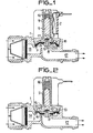
- - les figures 1 et 2 représentent une électrovanne, de type connu, respectivement en position ouverte et en position fermée ;
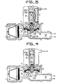
- - les figures 3 et 4 représentent une électrovanne suivant l'invention, respectivement en position fermée et en position ouverte.
- - Figures 1 and 2 show a solenoid valve, of known type, respectively in the open position and in the closed position;
- - Figures 3 and 4 show a solenoid valve according to the invention, respectively in the closed position and in the open position.
L'électrovanne de type connu, montrée en figures 1 et 2, est une électrovanne à ouverture pilotée et à une sortie. Cette électrovanne comporte un corps 1 surmonté d'un capuchon 9 tous deux en matériau non-magnétique. Autour de ce capuchon 9 est disposé une bobine 2 d'un électro-aimant. muni d'une armature non représentée. Dans le capuchon 9 est disposé un noyau 5- mobile en matériau magnétique, ce noyau 5 étant muni, à l'une de ses extrémités, d'un joint 6 d'étanchéité. (en caoutchouc par exemple). Un clapet 7 mobile, destiné à venir en appui sur un siège 8 de clapet, est rendu solidaire du corps 1 de l'électrovanne au moyen d'une membrane 10 souple munie d'un orifice dit orifice pilote 12 de clapet. Cette membrane 10 constitue un joint d'étanchéité lorsqu'elle est appliquée sur le siège 8 de clapet (l'électrovanne est alors en position fermée comme montré en figure 2). Ce clapet est muni par ailleurs d'un canal central dit canal 13 de fuite ouvert à ses deux extrémités.L'électrovanne de type connu comprend encore une chambre 14 dite chambre amont en communication avec le réseau d'alimentation en eau, une chambre 15 pilote pouvant être mise en communication avec la chambre 14 au moyen de l'orifice pilote 12, et une tubulure 17 d'évacuation.The known type of solenoid valve, shown in FIGS. 1 and 2, is a solenoid valve with controlled opening and with an output. This solenoid valve comprises a body 1 surmounted by a
Lorsque cette électrovanne, de type connu, est au repos, la bobine 2 étant hors tension, le joint 6 du noyau mobile 5 vient, sous l'effet du poids du noyau 5 ou sous l'action d'un ressort 16, s'appliquer sur l'orifice amont de la tubulure 17 d'évacuation et l'obture (figure 2). L'électrovanne est fermée. Quand la bobine est mise sous tension, le noyau mobile 5, attiré par l'électro-aimant, dégage l'orifice amont de la tubulure 17 et le fluide peut alors s'écouler au travers de l'électrovanne (figure 1).When this solenoid valve, of known type, is at rest, the
Cependant, cette électrovanne de type connu, nécessite une course du noyau mobile 5 suffisamment importante pour que, d'une part, l'orifice de fuite 17 soit dégagé et que, d'autre part, ce noyau mobile 5 soit suffisamment éloigné de l'orifice amont de la tubulure 17 pour que le clapet 7 ne vienne pas, au moment de l'ouverture de l'électrovanne, s'appliquer de nouveau sur ce noyau mobile 5.However, this solenoid valve of known type requires a sufficiently large stroke of the
L'électrovanne suivant l'invention, de faible consommation électrique, fonctionnant avec un faible déplacement du noyau mobile, ne présente pas ces inconvénients.The solenoid valve according to the invention, of low electrical consumption, operating with a small displacement of the movable core, does not have these drawbacks.
Dans la description qui va suivre, les éléments communs à l'électrovanne suivant l'invention et aux électrovannes de type connu seront repérés avec les mêmes références.In the description which follows, the elements common to the solenoid valve according to the invention and to the solenoid valves of known type will be identified with the same references.
L'électrovanne suivant l'invention comporte, comme le montre les figures 3 et 4, un corps 1 d'électrovanne surmonté d'un capuchon 9 autour duquel est placée une bobine 2 d'un électro-aimant muni d'une armature (non représenté), cette bobine 2 assurant le déplacement d'un noyau mobile 50 en matériau ferro-magnétique, ce noyau mobile 50 disposé dans le capuchon 9, étant dans l'exemple représenté en figures 3 et 4,. muni à l'une de ses extrémités d'un joint 60 d'étanchéité. En vis-à-vis du noyau mobile 50 est disposé un canal de fuite 130 qui est fixe par rapport à l'électrovanne et non plus solidaire du clapet mobile comme c'est le cas dans l'électrovanne de l'art antérieur.The solenoid valve according to the invention comprises, as shown in Figures 3 and 4, a solenoid valve body 1 surmounted by a
Ce canal de fuite 130, dans l'exemple de réalisation représenté en figures 3 et 4 comprend une tubulure cylindrique 131 surmontée d'un plateau circulaire 132 coaxial à la tubulure 131, muni en son centre d'un orifice de fuite 133 calibré, et muni à sa périphérie d'orifices de passage 137 permettant la circulation du fluide.This
L'électrovanne suivant l'invention comporte, de plus, un clapet 70 mobile qui est rendu solidaire du corps 1 de l'électrovanne au moyen d'une membrane 10 souple annulaire, dont le bord 11 intérieur, plan, vient s'insérer latéralement dans ce clapet 70, le bord extérieur étant fixé sur le corps 1. La membrane 10 constitue un joint d'étanchéité entre le clapet 70 et un siège 8 de clapet lorsque le bord 11 est appliqué sur le siège 8 de clapet (l'électrovanne est alors en position fermée comme le montre la figure 3). Le bord 11 plan de la membrane 10 est munie d'un orifice 12 dit orifice pilote du clapet.The solenoid valve according to the invention further comprises a
Dans l'électrovanne suivant l'invention, le clapet 70 est muni d'un canal axial 134 destiné au passage de la tubulure de fuite 131, ce clapet 70 pouvant se déplacer librement le long de cette tubulure 131 qui est fixe. Le pilotage de cette électrovanne est donc indépendant du clapet 70.In the solenoid valve according to the invention, the
L'électrovanne suivant l'invention comprend encore une chambre amont en communication avec le réseau d'alimentation en eau, une chambre 15 pilote pouvant être mise en communication avec la chambre 14 au moyen de l'orifice pilote 12, et une tubulure d'évacuation 17.The solenoid valve according to the invention also comprises an upstream chamber in communication with the water supply network, a
L'électrovanne suivant l'invention comporte, de plus, dans l'exemple de réalisation montré en figures 3 et 4, un noyau fixe 136 solidaire de l'électro-aimant et qui permet de diminuer l'entrefer de cet électro-aimant et du noyau mobile 50 et donc de diminuer l'énergie nécessaire au pilotage de l'électrovanne. En effet, dans ce cas, le noyau mobile 50 étant à courte distance du noyau fixe 136, l'énergie nécessaire à l'appel du noyau mobile 50 et l'énergie nécessaire au maintien de ce noyau mobile 50 sont très réduites par rapport aux énergies habituellement utilisées pour le fonctionnement des électrovannes pilotées de type connu.The solenoid valve according to the invention further comprises, in the embodiment shown in Figures 3 and 4, a
Comme montré en figures 3 et 4, un ressort 160 peut être disposé entre le noyau mobile 50 et le noyau fixe 136, ce ressort 160 étant destiné à pousser le noyau mobile 50 contre l'orifice de fuite 133 lorsque la tension appliquée sur la bobine 2 de l'électro-aimant est supprimée.As shown in Figures 3 and 4, a
Afin d'assurer l'étanchéité entre la chambre pilote 15 et la tubulure 17 d'évacuation, un manchon 135, en forme de soufflet, est placé autour de la tubulure de fuite 131, une- des extrémités du manchon 135 étant fixée sur le clapet 70 et l'autre extrémité étant fixée à la jonction du plateau circulaire 132 et- de la tubulure de fuite 131.In order to ensure the seal between the
Ce manchon 135 est de forme telle et en matériau (caoutchouc ou matière plastique par exemple) tel qu'il reste étanche quelle que soit la pression qui lui est appliquée et résiste en particulier aux forces d'écrasement dues à la différence de pression entre la chambre pilote 15 et la tubulure 17 d'évacuation. Il permet l'ouverture du clapet 70 aux très basses pressions et forme ressort, ce qui permet d'assurer une bonne fermeture du clapet 70 sur le siège 8 de ce clapet.This
En fonctionnement, lorsque l'électrovanne suivant l'invention est au repos, la bobine 2 étant hors tension, le joint 60 du noyau mobile 50 vient s'appliquer sur l'orifice de fuite 133 et l'obture. La chambre pilote 15 est alors à la pression de la chambre amont 14 (pression du réseau d'alimentation) grâce à l'orifice pilote 12, ce qui maintient la partie Il de la membrane 10 du clapet 70 plaquée sur le siège 8 de clapet. L'électrovanne est fermée.In operation, when the solenoid valve according to the invention is at rest, the
Lorsque la bobine 2 est mise sous tension, le noyau mobile 50 est attiré par le noyau fixe 136 associé à l'électro-aimant et dégage alors l'orifice 133 de la tubulure de fuite 130. Le fluide de la chambre pilote 15 peut alors s'écouler dans la tubulure 17 d'évacuation. En effet, l'orifice de fuite 133 est calibré de telle sorte que sa perte de charge soit inférieure à celle de l'orifice pilote 12, ce qui met la chambre pilote 15 en dépression par rapport à la chambre amont 14. La résultante des forces appliquées sur le clapet 70 est alors telle que ce clapet 70 s'éloigne du siège 8 de clapet. L'électrovanne est ouverte et le reste tant que la bobine 2 est alimentée en tension. Cette tension peut être inférieure aux tensions habituellement utilisées, car l'effort nécessaire au maintien du noyau mobile 50 sensiblement contre le noyau fixe 136 est très faible. L'énergie consommée est alors très réduite.When the
Lorsque la bobine 2 cesse d'être alimentée en tension, le noyau mobile 50, par son propre poids, ou plus habituellement grâce à un ressort 160, vient de nouveau s'appliquer sur l'orifice de fuite 133. La pression remonte dans la chambre pilote 15 et la résultante des forces appliquées sur le clapet 70 a pour effet de ramener ce clapet 70 sur le siège 8 de clapet.When the
A titre d'exemple, une électrovanne suivant l'invention, telle que décrite dans ce qui précède, nécessite pour son fonctionnement une puissance à l'appel de 600 milliwatts environ seulement, alors que la puissance de décrochage n'est que de quelques milliwatts.For example, a solenoid valve according to the invention, as described in the foregoing, requires for its operation a power on call of only about 600 milliwatts, while the stall power is only a few milliwatts .
Ceci permet donc l'adaptation aisée de cette électrovanne à une commande électronique, les caractéristiques de cette électrovanne suivant l'invention étant au moins aussi satisfaisantes que celles des électrovannes de type connu nécessitant une énergie électrique de fonctionnement bien supérieure.This therefore allows easy adaptation of this solenoid valve to an electronic control, the characteristics of this solenoid valve according to the invention being at least as satisfactory as those of the solenoid valves of known type requiring much higher operating electrical energy.
Il est à noter que l'énergie nécessaire à l'élimination de l'électrovanne suivant l'invention peut encore être diminuée en choisissant un ressort 160 de grande élasticité. Il est même possible de supprimer ce ressort 160 en choisissant convenablement l'orientation de l'électrovanne, la fermeture de l'orifice de fuite 133 par le joint 60 du noyau 50 étant assurée par le poids de ce noyau 50. Dans ce cas, il peut être avantageux de disposer entre le noyau mobile 50 et le noyau fixe 136 une rondelle en matériau non magnétique.It should be noted that the energy required for eliminating the solenoid valve according to the invention can be further reduced by choosing a
Il est également possible, pour diminuer l'énergie appliquée sur la bobine 2 de l'électro-aimant, d'augmenter le diamètre du noyau mobile 50 et/ou d'augmenter le nombre de spires de la bobine 2.It is also possible, to decrease the energy applied to the
Claims (6)
Priority Applications (1)
| Application Number | Priority Date | Filing Date | Title |
|---|---|---|---|
| AT81401646T ATE10779T1 (en) | 1980-11-04 | 1981-10-20 | ELECTROMAGNETIC VALVE. |
Applications Claiming Priority (2)
| Application Number | Priority Date | Filing Date | Title |
|---|---|---|---|
| FR8023521 | 1980-11-04 | ||
| FR8023521A FR2493465B1 (en) | 1980-11-04 | 1980-11-04 | SOLENOID VALVE AND WASHING MACHINE PROVIDED WITH SUCH A SOLENOID VALVE |
Publications (2)
| Publication Number | Publication Date |
|---|---|
| EP0051517A1 true EP0051517A1 (en) | 1982-05-12 |
| EP0051517B1 EP0051517B1 (en) | 1984-12-12 |
Family
ID=9247658
Family Applications (1)
| Application Number | Title | Priority Date | Filing Date |
|---|---|---|---|
| EP81401646A Expired EP0051517B1 (en) | 1980-11-04 | 1981-10-20 | Electromagnetic valve |
Country Status (4)
| Country | Link |
|---|---|
| EP (1) | EP0051517B1 (en) |
| AT (1) | ATE10779T1 (en) |
| DE (1) | DE3167742D1 (en) |
| FR (1) | FR2493465B1 (en) |
Cited By (8)
| Publication number | Priority date | Publication date | Assignee | Title |
|---|---|---|---|---|
| GB2123531A (en) * | 1982-07-13 | 1984-02-01 | Industry The Secretary Of Stat | Valves |
| FR2543652A1 (en) * | 1983-03-29 | 1984-10-05 | Elbi Int Spa | Electromagnetically actuated flow valve |
| DE3627543A1 (en) * | 1985-08-15 | 1987-03-12 | Smc Corp | SOLENOID VALVE |
| US5125621A (en) * | 1991-04-01 | 1992-06-30 | Recurrent Solutions Limited Partnership | Flush system |
| EP0685672A1 (en) * | 1994-05-31 | 1995-12-06 | Daewoo Electronics Co., Ltd | Fluid-supply valves |
| WO2005080838A2 (en) | 2004-02-23 | 2005-09-01 | Y. Stern Engineering (1989) Ltd. | Diaphragm for pilot valve |
| CN110005860A (en) * | 2019-05-17 | 2019-07-12 | 余姚市永创电磁阀有限公司 | A kind of PFA material diaphragm unit and solenoid valve |
| WO2023024195A1 (en) * | 2021-08-21 | 2023-03-02 | 浙江鸿友压缩机制造有限公司 | Pilot-operated electronic unloading valve and compressor system equipped with same |
Families Citing this family (2)
| Publication number | Priority date | Publication date | Assignee | Title |
|---|---|---|---|---|
| US20110017303A1 (en) * | 2008-01-02 | 2011-01-27 | Microflow International Pty Limited | Time flow valve |
| EP3752758B1 (en) | 2018-02-12 | 2023-08-16 | Ceme S.p.A. | Magnetically-operable shutter assembly |
Citations (3)
| Publication number | Priority date | Publication date | Assignee | Title |
|---|---|---|---|---|
| FR1110895A (en) * | 1954-07-19 | 1956-02-17 | Solenoid valves | |
| FR72694E (en) * | 1957-12-30 | 1960-04-22 | Valve | |
| US3368582A (en) * | 1965-04-22 | 1968-02-13 | American Radiator & Standard | Pilot-operated valve including removable filter |
-
1980
- 1980-11-04 FR FR8023521A patent/FR2493465B1/en not_active Expired
-
1981
- 1981-10-20 EP EP81401646A patent/EP0051517B1/en not_active Expired
- 1981-10-20 DE DE8181401646T patent/DE3167742D1/en not_active Expired
- 1981-10-20 AT AT81401646T patent/ATE10779T1/en active
Patent Citations (3)
| Publication number | Priority date | Publication date | Assignee | Title |
|---|---|---|---|---|
| FR1110895A (en) * | 1954-07-19 | 1956-02-17 | Solenoid valves | |
| FR72694E (en) * | 1957-12-30 | 1960-04-22 | Valve | |
| US3368582A (en) * | 1965-04-22 | 1968-02-13 | American Radiator & Standard | Pilot-operated valve including removable filter |
Cited By (10)
| Publication number | Priority date | Publication date | Assignee | Title |
|---|---|---|---|---|
| GB2123531A (en) * | 1982-07-13 | 1984-02-01 | Industry The Secretary Of Stat | Valves |
| FR2543652A1 (en) * | 1983-03-29 | 1984-10-05 | Elbi Int Spa | Electromagnetically actuated flow valve |
| DE3627543A1 (en) * | 1985-08-15 | 1987-03-12 | Smc Corp | SOLENOID VALVE |
| US4717116A (en) * | 1985-08-15 | 1988-01-05 | Smc Corporation | Pilot mode two-port solenoid valve |
| US5125621A (en) * | 1991-04-01 | 1992-06-30 | Recurrent Solutions Limited Partnership | Flush system |
| EP0685672A1 (en) * | 1994-05-31 | 1995-12-06 | Daewoo Electronics Co., Ltd | Fluid-supply valves |
| US5573224A (en) * | 1994-05-31 | 1996-11-12 | Daewoo Electronics Co., Ltd. | Water-supply valve of a washing machine |
| WO2005080838A2 (en) | 2004-02-23 | 2005-09-01 | Y. Stern Engineering (1989) Ltd. | Diaphragm for pilot valve |
| CN110005860A (en) * | 2019-05-17 | 2019-07-12 | 余姚市永创电磁阀有限公司 | A kind of PFA material diaphragm unit and solenoid valve |
| WO2023024195A1 (en) * | 2021-08-21 | 2023-03-02 | 浙江鸿友压缩机制造有限公司 | Pilot-operated electronic unloading valve and compressor system equipped with same |
Also Published As
| Publication number | Publication date |
|---|---|
| DE3167742D1 (en) | 1985-01-24 |
| ATE10779T1 (en) | 1984-12-15 |
| FR2493465A1 (en) | 1982-05-07 |
| EP0051517B1 (en) | 1984-12-12 |
| FR2493465B1 (en) | 1985-09-13 |
Similar Documents
| Publication | Publication Date | Title |
|---|---|---|
| BE1006300A4 (en) | VALVE COMPRISING A TILTING SHUTTER AND AN INSULATION MEMBRANE. | |
| EP0051517B1 (en) | Electromagnetic valve | |
| EP2045496B1 (en) | Balanced pressure flap gate | |
| US4082116A (en) | Electromagnetic two-way valve | |
| EP0619003B1 (en) | A cartridge with plates of hard material for a single-control faucet | |
| BE1000713A4 (en) | Off valve and flow control. | |
| FR2727736A1 (en) | VALVE CONTROLLED BY A FLUID | |
| FR2479401A1 (en) | RINSING VALVE AND PISTON FOR THIS FAUCET | |
| IL156797A (en) | Diaphragm and hydraulically-operated valve using same | |
| EP0390248B1 (en) | Anti-siphoning device for cartridge-type taps having flat plates for flow control | |
| EP1217275B1 (en) | Bi-stable electromagnetic micro-valve | |
| EP0268521B1 (en) | Lock valve | |
| FR2918040A3 (en) | LIQUID DISPENSER | |
| FR2727734A1 (en) | Control valve with two flow characteristic, used in industrial and heating purposes | |
| EP0682615B1 (en) | Electrically-operated proportional pneumatic valve | |
| EP2553301A1 (en) | Tap with delayed closing | |
| FR2595432A1 (en) | NON-RETURN VALVE ASSEMBLY, PARTICULARLY FOR PRESSURIZED WATER REACTOR | |
| LU100577B1 (en) | Pilot controlled electromagnetic valve with auxiliary piston | |
| FR2873778A1 (en) | CLAMP ELEMENT FOR BALANCED PRESSURE REDUCER | |
| EP0029387A1 (en) | Disconnector for potable-water conduit | |
| FR2543652A1 (en) | Electromagnetically actuated flow valve | |
| KR200224531Y1 (en) | A check valve | |
| CN220016091U (en) | Stop valve | |
| KR20020045949A (en) | A check valve | |
| SU811041A1 (en) | Electromagnetic valve with annular nozzle |
Legal Events
| Date | Code | Title | Description |
|---|---|---|---|
| PUAI | Public reference made under article 153(3) epc to a published international application that has entered the european phase |
Free format text: ORIGINAL CODE: 0009012 |
|
| AK | Designated contracting states |
Designated state(s): AT BE CH DE FR GB IT LI LU NL SE |
|
| 17P | Request for examination filed |
Effective date: 19820818 |
|
| RAP1 | Party data changed (applicant data changed or rights of an application transferred) |
Owner name: SOCIETE ELECTRO MECANIQUE DU NIVERNAIS SELNI |
|
| ITF | It: translation for a ep patent filed |
Owner name: JACOBACCI & PERANI S.P.A. |
|
| GRAA | (expected) grant |
Free format text: ORIGINAL CODE: 0009210 |
|
| AK | Designated contracting states |
Designated state(s): AT BE CH DE FR GB IT LI LU NL SE |
|
| REF | Corresponds to: |
Ref document number: 10779 Country of ref document: AT Date of ref document: 19841215 Kind code of ref document: T |
|
| REF | Corresponds to: |
Ref document number: 3167742 Country of ref document: DE Date of ref document: 19850124 |
|
| PLBE | No opposition filed within time limit |
Free format text: ORIGINAL CODE: 0009261 |
|
| STAA | Information on the status of an ep patent application or granted ep patent |
Free format text: STATUS: NO OPPOSITION FILED WITHIN TIME LIMIT |
|
| PG25 | Lapsed in a contracting state [announced via postgrant information from national office to epo] |
Ref country code: LU Free format text: LAPSE BECAUSE OF NON-PAYMENT OF DUE FEES Effective date: 19851031 |
|
| PGFP | Annual fee paid to national office [announced via postgrant information from national office to epo] |
Ref country code: NL Payment date: 19851031 Year of fee payment: 5 Ref country code: AT Payment date: 19851031 Year of fee payment: 5 |
|
| 26N | No opposition filed | ||
| PG25 | Lapsed in a contracting state [announced via postgrant information from national office to epo] |
Ref country code: AT Effective date: 19861020 |
|
| PG25 | Lapsed in a contracting state [announced via postgrant information from national office to epo] |
Ref country code: SE Effective date: 19861021 |
|
| PG25 | Lapsed in a contracting state [announced via postgrant information from national office to epo] |
Ref country code: LI Effective date: 19861031 Ref country code: CH Effective date: 19861031 Ref country code: BE Effective date: 19861031 |
|
| BERE | Be: lapsed |
Owner name: SOC. ELECTRO MECANIQUE DU NIVERNAIS SELNI Effective date: 19861031 |
|
| PG25 | Lapsed in a contracting state [announced via postgrant information from national office to epo] |
Ref country code: NL Effective date: 19870501 |
|
| NLV4 | Nl: lapsed or anulled due to non-payment of the annual fee | ||
| PG25 | Lapsed in a contracting state [announced via postgrant information from national office to epo] |
Ref country code: FR Free format text: LAPSE BECAUSE OF NON-PAYMENT OF DUE FEES Effective date: 19870630 |
|
| REG | Reference to a national code |
Ref country code: CH Ref legal event code: PL |
|
| GBPC | Gb: european patent ceased through non-payment of renewal fee | ||
| PG25 | Lapsed in a contracting state [announced via postgrant information from national office to epo] |
Ref country code: DE Effective date: 19870701 |
|
| REG | Reference to a national code |
Ref country code: FR Ref legal event code: ST |
|
| PG25 | Lapsed in a contracting state [announced via postgrant information from national office to epo] |
Ref country code: GB Effective date: 19881118 |
|
| EUG | Se: european patent has lapsed |
Ref document number: 81401646.5 Effective date: 19870812 |