EP0052463A1 - Soft decision convolutional code transmission system - Google Patents
Soft decision convolutional code transmission system Download PDFInfo
- Publication number
- EP0052463A1 EP0052463A1 EP81305236A EP81305236A EP0052463A1 EP 0052463 A1 EP0052463 A1 EP 0052463A1 EP 81305236 A EP81305236 A EP 81305236A EP 81305236 A EP81305236 A EP 81305236A EP 0052463 A1 EP0052463 A1 EP 0052463A1
- Authority
- EP
- European Patent Office
- Prior art keywords
- transmission system
- transmitter
- data
- receiver
- bits
- Prior art date
- Legal status (The legal status is an assumption and is not a legal conclusion. Google has not performed a legal analysis and makes no representation as to the accuracy of the status listed.)
- Granted
Links
Images


Classifications
-
- H—ELECTRICITY
- H04—ELECTRIC COMMUNICATION TECHNIQUE
- H04L—TRANSMISSION OF DIGITAL INFORMATION, e.g. TELEGRAPHIC COMMUNICATION
- H04L1/00—Arrangements for detecting or preventing errors in the information received
- H04L1/004—Arrangements for detecting or preventing errors in the information received by using forward error control
- H04L1/0056—Systems characterized by the type of code used
- H04L1/0059—Convolutional codes
-
- H—ELECTRICITY
- H03—ELECTRONIC CIRCUITRY
- H03M—CODING; DECODING; CODE CONVERSION IN GENERAL
- H03M13/00—Coding, decoding or code conversion, for error detection or error correction; Coding theory basic assumptions; Coding bounds; Error probability evaluation methods; Channel models; Simulation or testing of codes
- H03M13/37—Decoding methods or techniques, not specific to the particular type of coding provided for in groups H03M13/03 - H03M13/35
- H03M13/39—Sequence estimation, i.e. using statistical methods for the reconstruction of the original codes
- H03M13/41—Sequence estimation, i.e. using statistical methods for the reconstruction of the original codes using the Viterbi algorithm or Viterbi processors
-
- H—ELECTRICITY
- H04—ELECTRIC COMMUNICATION TECHNIQUE
- H04L—TRANSMISSION OF DIGITAL INFORMATION, e.g. TELEGRAPHIC COMMUNICATION
- H04L1/00—Arrangements for detecting or preventing errors in the information received
- H04L1/004—Arrangements for detecting or preventing errors in the information received by using forward error control
- H04L1/0045—Arrangements at the receiver end
- H04L1/0054—Maximum-likelihood or sequential decoding, e.g. Viterbi, Fano, ZJ algorithms
-
- H—ELECTRICITY
- H04—ELECTRIC COMMUNICATION TECHNIQUE
- H04L—TRANSMISSION OF DIGITAL INFORMATION, e.g. TELEGRAPHIC COMMUNICATION
- H04L25/00—Baseband systems
- H04L25/02—Details ; arrangements for supplying electrical power along data transmission lines
- H04L25/06—Dc level restoring means; Bias distortion correction ; Decision circuits providing symbol by symbol detection
- H04L25/067—Dc level restoring means; Bias distortion correction ; Decision circuits providing symbol by symbol detection providing soft decisions, i.e. decisions together with an estimate of reliability
-
- H—ELECTRICITY
- H04—ELECTRIC COMMUNICATION TECHNIQUE
- H04L—TRANSMISSION OF DIGITAL INFORMATION, e.g. TELEGRAPHIC COMMUNICATION
- H04L27/00—Modulated-carrier systems
- H04L27/32—Carrier systems characterised by combinations of two or more of the types covered by groups H04L27/02, H04L27/10, H04L27/18 or H04L27/26
- H04L27/34—Amplitude- and phase-modulated carrier systems, e.g. quadrature-amplitude modulated carrier systems
- H04L27/3405—Modifications of the signal space to increase the efficiency of transmission, e.g. reduction of the bit error rate, bandwidth, or average power
- H04L27/3416—Modifications of the signal space to increase the efficiency of transmission, e.g. reduction of the bit error rate, bandwidth, or average power in which the information is carried by both the individual signal points and the subset to which the individual points belong, e.g. using coset coding, lattice coding, or related schemes
- H04L27/3427—Modifications of the signal space to increase the efficiency of transmission, e.g. reduction of the bit error rate, bandwidth, or average power in which the information is carried by both the individual signal points and the subset to which the individual points belong, e.g. using coset coding, lattice coding, or related schemes in which the constellation is the n - fold Cartesian product of a single underlying two-dimensional constellation
- H04L27/3433—Modifications of the signal space to increase the efficiency of transmission, e.g. reduction of the bit error rate, bandwidth, or average power in which the information is carried by both the individual signal points and the subset to which the individual points belong, e.g. using coset coding, lattice coding, or related schemes in which the constellation is the n - fold Cartesian product of a single underlying two-dimensional constellation using an underlying square constellation
-
- H—ELECTRICITY
- H04—ELECTRIC COMMUNICATION TECHNIQUE
- H04L—TRANSMISSION OF DIGITAL INFORMATION, e.g. TELEGRAPHIC COMMUNICATION
- H04L27/00—Modulated-carrier systems
- H04L27/32—Carrier systems characterised by combinations of two or more of the types covered by groups H04L27/02, H04L27/10, H04L27/18 or H04L27/26
- H04L27/34—Amplitude- and phase-modulated carrier systems, e.g. quadrature-amplitude modulated carrier systems
- H04L27/38—Demodulator circuits; Receiver circuits
- H04L27/3845—Demodulator circuits; Receiver circuits using non - coherent demodulation, i.e. not using a phase synchronous carrier
- H04L27/3854—Demodulator circuits; Receiver circuits using non - coherent demodulation, i.e. not using a phase synchronous carrier using a non - coherent carrier, including systems with baseband correction for phase or frequency offset
- H04L27/3872—Compensation for phase rotation in the demodulated signal
Definitions
- the present invention relates to transmission systems and more particularly to a transmission system incorporating a transmitter and a receiver in which information is transmitted by a code incorporating redundancy to allow error correction with soft decision at the receiver.
- the present invention provides a transmission system for the transmission of data-from a transmitter to a receiver including a transmitter containing a convolutional encoder and a signal mapping device connected thereto to produce a two dimensional coded output signal, and including a receiver containing a convolutional decoder with soft decision decoding, connected to a reverse mapping means to produce output data.
- the present invention also provides a tran smitter and a receiver for the transmission system and is designed for use with a modem in which both transmitter and receiver are incorporated.
- the present modem transmitter shown in Figure 1 converts groups of six data bits into symbols, each of which may take one of 64 values.
- Quadrature amplitude modulation is used and the transmitted points in the complex signal space are arranged in an 8 by 8 square grid.
- the error correcting code converts groups of five data bits into groups of six bits which are then converted into the complex signal space co-ordinates.
- the redundancy is exploited to obtain the
- the error correcting modem has a user data rate of 13.3 kb/s. If desired, other data rates may be used with the appropriate modem design.
- Data is received at the terminal 10 in a serial form and converted by a serial to parallel converter 12 into parallel five-bit data words.
- the conversion of 5-bit data words into 6-bit words is achieved by passing the four most significant bits X5 through X2 unchanged and using a t rate convolutional encoder 14 (see Figure 3) to convert the least significant data bit X1 into the two least significant bits of the 6-bit word (see Figure 3).
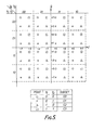
- the 6-bit words are mapped into the 64-point complex signal space by mapping device 16 according to the mapping shown in Figure 5 and are transmitted to line by modulators (not shown).
- the mapping device 16 maps bits Y O through Y 5 to co-ordinates I, Q as shown i..n Figure 5. Each co-ordinate is transmitted as a 4 bit coded amplitude.
- This principle may be extended using for example 7-bit _ data words by passing the six most significant bits through unchanged and using a convolutional encoder on the last bit.
- Other convolutional encoding may be used such as a 2/3 rate encoder operating on the two least significant bits.
- mapping configurations such as equilateral triagles, rhombus or hexagon may be used.
- soft decision information from the demodulator and equaliser (not shown) is used by the Viterbi algorithm detector 20 to decide which set of two convolutionally encoded bits (Y 1 and Y O ) was most likely to have been transmitted.
- the two corrected bits are used to set up threshold levels between the 16 points assigned to these two bits.
- the region in which the received point lies determines which of the sixteen was most likely to have been transmitted. From this the 6-bit coded word is found using the reverse mapping apparatus 22.
- the 5-bit data word is then obtained as shown in Figure 2.
- Q ⁇ x ⁇ is the Gaussian error probability function.
- N 1 and N 2 are constants which are not very different from each other. From the above it is seen that the theoretically maximum coding gain of 133kb/s coded over 16 kb/s uncoded is about 6 dB.
- the transmitter of Figure 1 is organised to transmit 5 data bits per symbol at 13.3' kb/s. In actual fact 6 bits per symbol are taken for onward transmission. The 6th bit is the added redundancy required by the Viterbi algorithm. In order to provide error correction, five data bits are therefore mapped onto a set of 6 bits by carrying over the 4 most significant bits unchanged but generating the 5th and 6th by convolutionally encoding the least significant bit in the uncoded domain. The circuit that performs this operation appears in Figure 3. Functional operation of the convolutional encoder can be appreciated by considering an example:
- mapping PROM 16 that maps the 6-bit word onto the signal constellation is shown.
- the scheme employed partitions the 6-bit word into two sections.
- the two convolutionally encoded bits Y 1 Y 0 are the C points (CQC1,C2,C3) shown repeated in the grid structure of Figure 5.
- the four most significant bits define the grid square in which a C point lies.
- Mapping is two dimensional Gray.
- the received symbol I and Q co-ordinates define which C point has arrived.
- the Viterbi algorithm block 20 generates the trellis diagram in reverse. The principle of the Viterbi algorithm is illustrated by first considering hard decision decoding instead of soft decision decoding which is_ actually used. Each current node has two transitions arriving at it. As a dibit Y 1 Y 0 is received the algorithm decides which transition would have been more likely by computing scores to each transition. This is done for all four nodes, so ending with a set of 4 transitions, one to each node.
- the score is made up of two components, the nodal score at the origin plus the incremental score which is equal to the Hamming distance between the transition code and the Y 1 Y 0 dibit received. This score is calculated for both transitions and the transition with the lower score is chosen. In this way a network of transitions develops.
- Figure 6 shows the decoding process. Note that if the two transitions yield the same new score one of them can be chosen arbitrarily.
- Obtaining X i from the trellis diagram involves tracing back a path made of chosen transitions over L symbols where L is the search length.
- the path begins at the current node with the least score.
- the Lth transition gives the X 1 bit estimated to have been transmitted.
- the X 1 bit estimate can be obtained by following the thick line.
- a search length of 6 is taken for simplicity.
- the trellis diagram is continually built up in the same manner and the X i value 6 symbols ago is extracted.
- Hamming distances are not used.
- the C points in the signal constellation appear in groups of four. Thus every symbol position can be associated with the four C points C o C 1 C 2 C 3 either within a grid square or overlapping two or more squares depending on the position of the symbol in the IQ plane. So, in place of Hamming distance based incremental scoring, the square of the Euclidean distance between the point and the relevant pair of C points ( transitions) is taken as shown in Figure 9.
- bits 0 - 3 from the land Q co-ordinates are used to generate an 8-bit address for a look up table that stores the incremental scores. See Figure 10 for a table of co-ordinate values. 3its 3, 4 and 7 are hard decision bits which uniquely define each of the eight levels. Again a trellis is built up, decoding being performed in the same way as in the example above.
- Figure 11 shows a received symbol position Rx and the chosen C point CC. To ensure that the square surrounds both points the Q horizontal dashed lines should be moved up by 2d. In other words 1 ⁇ 2d must be subtracted from the Q co-ordinate value. Similarly the vertical dashed lines are translated left by 1 ⁇ 2d.
- the hard decision can now be taken by reading the codes Y 2 Y 3 Y 4 Y 5 as per Figure 5. This gives 4 bits of received information. The remaining two bits are the coded values for the chosen C point i.e. the Y 1 Y 0 dibit.
- the receiver hardware includes an 8085A microprocessor with associated I.C.'s 8155, 8212 and 2716.
- the 8155 is an I/O peripheral configured as two programmable 8-bit I/O ports (PA+PB) and one programmable 6-bit I/O port (PC). I and Q co-ordinates are fed to ports PA and PB respectively, while PC outputs the decoded but not de-mapped symbols.
- the first task for the microprocessor is to initialise memory locations and load constants into the relevant locations. Constants are 1) SCHLNG (L) which is the number of transitions traced over the trellis diagram,; 2) COUNT which is the number of consecutive symbols in which errors are counted before the error counter is reset; equivalent to integration 3) MAXCNT which is the error threshold determining when the algorithm performs a 90° rotation on the received IQ vector.
- An added feature to the standard Viterbi algorithm is software that rotates the received vector if the Viterbi process is found to be failing at an exceptionally high rate.
- the microprocessor is programmed to add a 90° phase shift to IQ before decoding is done. This is accomplished by a detector 30 which receives inputs from the requantiser 23 and delay blocks 24 and 26. The outputs of the detector 30 control rotators 32 and 34 which perform the rotation of the I and Q channel signals from the equaliser prior to decoding. Should this fail to rectify the high error-rate condition further 90° phase rotations are applied, until satisfactory decoding is obtained. In an ideal condition no phase rotation should be present between the transmitter and receiver.
- the parameter monitored to enable such a spurious condition to be detected is the comparison between the dibit assigned to the decoded C point (or TRANSITION) and the dibit formed by concatenating bit 3's from the two's complement representation of the delayed I and Q co-ordinates. Further mention of this techniaue will be made later.
- Block B sets up the rotational matrix to 0 i.e. no rotation. This is of course the most likely condition encountered in practice.
- the new scores (NS O-3 ) can how be calculated by adding incremental scores to the score previously calculated for the current origin, in a manner similar to the example given earlier. Since there are two possible transitions per current node the transition yielding the lesser score (implying a greater probability) is in each case chosen.
- L is 2 N where N is an integer.
- N is an integer.
- Each node is assigned two such lists for storing the transition and the origin. Updating or shift register action is realised by a pointer system.
- the beginning and end of the equivalent shift register are marked by a pointer address which is incremented once for every shift of the shift register.
- the same address may be used to extract information from the output end and then to store new information at the input end.
- the same pointer system is used to';provide the input and output addresses for the two co-ordinate lists.
- Block J refers to this part of the program.
- the first address in the "circular" origin list for the current node with the least score 0 contains the estimated previous node, known as the current origin.
- the next previous node, 2 is stored in the second address in the origin list for node 1 .
- the next previous node 3 is stored in the third address in the origin list for node 2 .
- T L Y 1 Y 0 . This is shown in the table below.
- This method eliminates the need to transfer survivor path sequences from one memory location to another which is implied in most descriptions of Viterbi algorithm implementation. The transfer of large amounts of data from one memory location to another is time consuming and should be avoided if possible, when processing time is at a premium, as in this case.
- the C point mapping, Y 1 Y 0 to Y 1 Y 0 is arranged as depicted in Figure 12. The purpose of this mapping is to translate the set of C point codes into another set that represents their actual physical position Y 1 Y 0 . Obviou b ly, one cannot always use such a parameter because it is valid only when the Viterbi system has settled down. Therefore the parameter should not be monitored during the first L symbols received. This is the function of Blocks M and N.-
- Block S the symbol error rate is checked, every symbol period. Should the threshold be attained the rotation matrix is updated by means of Block E. Otherwise the program continues to Block W where the six-bit word is derived by extracting two bits from I, two bits from Q and the two bits used for the C point code definition i.e. I 5 I 4 Q 5 Q 4 Y 1 Y 0 .
- Y 0 is just X 1 delayed by one delay unit. In other words if Y 2 through Y 5 are delayed by one unit and then tagged on to Y 0 the original 5-bit word is obtained.
- Demapping of the 4 most significant bits is performed using a logic arrangement with exclusive-OR gates in circuit 22.
- a latch provides the 1-symbol delay required to line up the Y 0 bit with bits through Y 2 through Y 5 .
- the 5-bit word is converted to a serial data stream with the parallel-to-serial converter before descrambling it and outputting the resultant data stream.
Abstract
Description
- The present invention relates to transmission systems and more particularly to a transmission system incorporating a transmitter and a receiver in which information is transmitted by a code incorporating redundancy to allow error correction with soft decision at the receiver.
- It is an object of the present invention to provide a data transmission modem suitable for digital data or digitised analogue communication at a given transmission rate and with a much lower error rate in the presence of a given signal-to-noise ratio than that for a system using no redundancy.
- Accordingly the present invention provides a transmission system for the transmission of data-from a transmitter to a receiver including a transmitter containing a convolutional encoder and a signal mapping device connected thereto to produce a two dimensional coded output signal, and including a receiver containing a convolutional decoder with soft decision decoding, connected to a reverse mapping means to produce output data.
- The present invention also provides a tran smitter and a receiver for the transmission system and is designed for use with a modem in which both transmitter and receiver are incorporated.
- The present invention will now be described by way of example with reference to the accompanying drawings in which:-
- Figure 1 shows in block diagrammatic form the encoding section of a transmitter according to the present invention,
- Figure 2 shows the decoding section of a receiver for reception and decoding of the signals from the transmitter of Figure 1,
- Figure 3 shows the convolutional encoder of Figure 1 ,
- Figure 4 shows a convolutional encoder trellis diagram illustrating possible transitions,
- Figure 5 shows the signal space mapping dragram for the decoding process,
- Figure 6 shows an exemplary trellis diagram showing the calculation of scores in the trellis development process,
- Figure 7 shows the Viterbi decoding process in an error-free case,
- Figure 8 shows the Viterbi decoding process with one error,
- Figure 9 shows the incremental scoring method according to the present invention,
- Figure 10 shows a diagram of values of one of the eight bit co-ordinates from the equaliser (see Figure 2) and also shows transmitted levels,
- Figures 11a and 11b respectively show in the requantisation process the normal position and the revised position of the thresholds after requantisation,
- Figure 12 shows the C point mapping process,
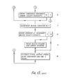
- Figure 13 shows a flow diagram for the error correction process carried out in the receiver Of Figure 2.
- The present modem transmitter shown in Figure 1 converts groups of six data bits into symbols, each of which may take one of 64 values. Quadrature amplitude modulation is used and the transmitted points in the complex signal space are arranged in an 8 by 8 square grid. The error correcting code converts groups of five data bits into groups of six bits which are then converted into the complex signal space co-ordinates. In the decoding process carried out in the receiver of Figure 2 the redundancy is exploited to obtain the
- groups of five data bits from the received sets of co-ordinates. The error correcting modem has a user data rate of 13.3 kb/s. If desired, other data rates may be used with the appropriate modem design. Data is received at the
terminal 10 in a serial form and converted by a serial toparallel converter 12 into parallel five-bit data words. - The conversion of 5-bit data words into 6-bit words is achieved by passing the four most significant bits X5 through X2 unchanged and using a t rate convolutional encoder 14 (see Figure 3) to convert the least significant data bit X1 into the two least significant bits of the 6-bit word (see Figure 3). The 6-bit words are mapped into the 64-point complex signal space by
mapping device 16 according to the mapping shown in Figure 5 and are transmitted to line by modulators (not shown). Themapping device 16 maps bits YO through Y5 to co-ordinates I, Q as shown i..n Figure 5. Each co-ordinate is transmitted as a 4 bit coded amplitude. This principle may be extended using for example 7-bit _ data words by passing the six most significant bits through unchanged and using a convolutional encoder on the last bit. Other convolutional encoding may be used such as a 2/3 rate encoder operating on the two least significant bits. Also other mapping configurations such as equilateral triagles, rhombus or hexagon may be used. - In the decoding process carried out in the decoder of Figure 2, soft decision information from the demodulator and equaliser (not shown) is used by the Viterbi
algorithm detector 20 to decide which set of two convolutionally encoded bits (Y1 and YO) was most likely to have been transmitted. The two corrected bits are used to set up threshold levels between the 16 points assigned to these two bits. The region in which the received point lies determines which of the sixteen was most likely to have been transmitted. From this the 6-bit coded word is found using thereverse mapping apparatus 22. The 5-bit data word is then obtained as shown in Figure 2. - The performance of the error correcting code expected from theory is as follows:
- Theory shows that for our error correcting code the probability of an error event would approach the following asymptote with increasing signal -to-noise ratio if unlimited number of soft decision bits were available.

- Q{x} is the Gaussian error probability function. For the 16 kb/s uncoded mode,

- Another mode was used for comparison: 133kb/s uncoded. For this mode the innermost 32 points of the 64-point space were transmitted. The "coding gain" of 133kb/s uncoded over 16 kb/s uncoded is approximately the ratio of their average signal powers for a given distance between nearest points and is about 3.2 dB.
- The theoretically maximum coding gain of 13.3 kb/s coded over 13.3 kb/s uncoded is therefore (6 - 3.2) = 2.8 dB.
- The transmitter of Figure 1 is organised to transmit 5 data bits per symbol at 13.3' kb/s. In
actual fact 6 bits per symbol are taken for onward transmission. The 6th bit is the added redundancy required by the Viterbi algorithm. In order to provide error correction, five data bits are therefore mapped onto a set of 6 bits by carrying over the 4 most significant bits unchanged but generating the 5th and 6th by convolutionally encoding the least significant bit in the uncoded domain. The circuit that performs this operation appears in Figure 3. Functional operation of the convolutional encoder can be appreciated by considering an example:
- The above sequence can also be derived by using the trellis diagram of Figure 4. Here,start at
current node 0 and trace the transition paths according to whether a 0 or 1 is received. Remember to return to the origin on the same level as the current node every time a transition has been made and relevant output segment Y1Y0 noted. - Referring to Figure 1 the
mapping PROM 16 that maps the 6-bit word onto the signal constellation is shown. The scheme employed partitions the 6-bit word into two sections. The two convolutionally encoded bits Y1Y0 are the C points (CQC1,C2,C3) shown repeated in the grid structure of Figure 5. The four most significant bits define the grid square in which a C point lies. Mapping is two dimensional Gray. - At the receiver shown in Figure 2 the received symbol I and Q co-ordinates define which C point has arrived. Once established, the Viterbi
algorithm block 20 generates the trellis diagram in reverse. The principle of the Viterbi algorithm is illustrated by first considering hard decision decoding instead of soft decision decoding which is_ actually used. Each current node has two transitions arriving at it. As a dibit Y1Y0 is received the algorithm decides which transition would have been more likely by computing scores to each transition. This is done for all four nodes, so ending with a set of 4 transitions, one to each node. The score is made up of two components, the nodal score at the origin plus the incremental score which is equal to the Hamming distance between the transition code and the Y1Y0 dibit received. This score is calculated for both transitions and the transition with the lower score is chosen. In this way a network of transitions develops. Figure 6 shows the decoding process. Note that if the two transitions yield the same new score one of them can be chosen arbitrarily. - Obtaining Xi from the trellis diagram involves tracing back a path made of chosen transitions over L symbols where L is the search length. The path begins at the current node with the least score. The Lth transition gives the X1 bit estimated to have been transmitted.
- In Figure 7 the trellis diagram, showing scores, is depicted.
- In Figure 8 a deliberate error inserted into a dibit shows how the Viterbi algorithm handles such an error. The path remains the same in both instances, in spite of the error.
- Under error conditions nodal scores can grow to large absolute values. To counter this a normalisation is performed after every set of nodal scores is calculated. The least score is subtracted from the 4 scores. An example of this feature appears in Figure 8.
- With the received trellis diagram set up, the X1 bit estimate can be obtained by following the thick line. In this example a search length of 6 is taken for simplicity. As more symbols arrive the trellis diagram is continually built up in the same manner and the Xi value 6 symbols ago is extracted.
- In the software implementation Hamming distances are not used. The C points in the signal constellation appear in groups of four. Thus every symbol position can be associated with the four C points CoC1C2C3 either within a grid square or overlapping two or more squares depending on the position of the symbol in the IQ plane. So, in place of Hamming distance based incremental scoring, the square of the Euclidean distance between the point and the relevant pair of C points (transitions) is taken as shown in Figure 9.

- In the receiver I and Q co-ordinates are stored as 8 bit words which give good resolution.
Bits 3its - One extra feature is the process of re quantisation as shown in Figure 11. This is a process whereby the hard decision thresholds, i.e. the dashed lines, are moved so that the received co-ordinate and the decoded C point associated with it lie in the same square with the C points forming the corner points of the square.
- Consider the following illustrative example. Figure 11 shows a received symbol position Rx and the chosen C point CC. To ensure that the square surrounds both points the Q horizontal dashed lines should be moved up by 2d. In other words ½d must be subtracted from the Q co-ordinate value. Similarly the vertical dashed lines are translated left by ½d.
- The hard decision can now be taken by reading the codes Y2Y3Y4Y5 as per Figure 5. This gives 4 bits of received information. The remaining two bits are the coded values for the chosen C point i.e. the Y1Y0 dibit.
- Available at the output of the receiver equaliser (not shown in Figure 2) for every symbol is a digitally encoded version of the I and Q co-ordinates. Eight bits (the most significant bits) are presented to the microprocessor based circuit. The receiver hardware includes an 8085A microprocessor with associated I.C.'s 8155, 8212 and 2716. The 8155 is an I/O peripheral configured as two programmable 8-bit I/O ports (PA+PB) and one programmable 6-bit I/O port (PC). I and Q co-ordinates are fed to ports PA and PB respectively, while PC outputs the decoded but not de-mapped symbols.
- The software implementation of the Viterbi algorithm involves a series of functions as described in Figure 13.
- The first task for the microprocessor is to initialise memory locations and load constants into the relevant locations. Constants are 1) SCHLNG (L) which is the number of transitions traced over the trellis diagram,; 2) COUNT which is the number of consecutive symbols in which errors are counted before the error counter is reset; equivalent to integration 3) MAXCNT which is the error threshold determining when the algorithm performs a 90° rotation on the received IQ vector. An added feature to the standard Viterbi algorithm is software that rotates the received vector if the Viterbi process is found to be failing at an exceptionally high rate. As there is no rotational symmetry or differential encoding in the FEC signal structure a spurious rotation permanently applied to the demodulated signal will result in a breakdown in the Viterbi decoding action. When such a state is recognised the microprocessor is programmed to add a 90° phase shift to IQ before decoding is done. This is accomplished by a
detector 30 which receives inputs from therequantiser 23 and delay blocks 24 and 26. The outputs of thedetector 30control rotators 32 and 34 which perform the rotation of the I and Q channel signals from the equaliser prior to decoding. Should this fail to rectify the high error-rate condition further 90° phase rotations are applied, until satisfactory decoding is obtained. In an ideal condition no phase rotation should be present between the transmitter and receiver. The parameter monitored to enable such a spurious condition to be detected is the comparison between the dibit assigned to the decoded C point (or TRANSITION) and the dibit formed by concatenatingbit 3's from the two's complement representation of the delayed I and Q co-ordinates. Further mention of this techniaue will be made later. - Returning to the flow diagram in Figure 13,Block B sets up the rotational matrix to 0 i.e. no rotation. This is of course the most likely condition encountered in practice.
- Due to the noise and other spurious conditions it is possible that the received amplitude will be outside the range indicated in Figure 10. This is remedied by limiting the value to +7 or -7 as given in Block F. For each current node, incremental scores are derived by considering the Euclidean distance between the received point and two of the four neighbouring C points in the signal constellation. The pair of the C points for which scores are computed is determined by the information shown in the trellis diagram, Figure 6. The variables DCO, DC1, DC2, DC3 contain the incremental scores for C points C0, C1, C2, C3 respectively. DC1 is the contents of a look-up table address, LOOK, formed by combining the 4 least significant bits of the I and Q co-ordinates giving an 8-bit address. The other incremental scores are obtained by inverting one or other or both halves of LOOK and using this modified 8-bit word as the look-up table address.
- The new scores (NSO-3) can how be calculated by adding incremental scores to the score previously calculated for the current origin, in a manner similar to the example given earlier. Since there are two possible transitions per current node the transition yielding the lesser score (implying a greater probability) is in each case chosen.
- All this information relating to the trellis diagram is stored in "circular" lists of length L. For convenience L is 2N where N is an integer. Each node is assigned two such lists for storing the transition and the origin. Updating or shift register action is realised by a pointer system.
- Instead of shifting the contents of one memory location to the next location for every location in the list, as in a shift register, the beginning and end of the equivalent shift register are marked by a pointer address which is incremented once for every shift of the shift register. To avoid using memory locations whose addresses increment indefinitely,the pointer address is incremented modulo L (=2N) so that all the memory locations are contained in a list'of size L. As a result, the same address may be used to extract information from the output end and then to store new information at the input end. The same pointer system is used to';provide the input and output addresses for the two co-ordinate lists. Block J refers to this part of the program.
- For every symbol period the expected transition, L symbols ago, is estimated by starting with the current node having the least score and then tracing a path back L symbols. The final transition traversed is taken to be the C point (TRANSITION) supposed to have been transmitted. Blocks K and L cover this operation.
- The method by which the trellis path is traced back L symbols is as follows:-
- With reference to Figure 7 the first address in the "circular" origin list for the current node with the least score0 contains the estimated previous node, known as the current origin. Let us suppose the current origin is node The next previous node,
 2, is stored in the second address in the origin list for node1. The next previous node3 is stored in the third address in the origin list for node2. When the final nodeL has been determined the final address in the transition list for node yields the desired output transition, TL=Y1Y0. This is shown in the table below. This method eliminates the need to transfer survivor path sequences from one memory location to another which is implied in most descriptions of Viterbi algorithm implementation. The transfer of large amounts of data from one memory location to another is time consuming and should be avoided if possible, when processing time is at a premium, as in this case.
- As was described earlier the algorithm incorporates a false rotation monitoring feature.
- The parameter used to check whether or not the receiver is operating in the wrong phase is the result of the comparison between the dibit assigned to a C point's position and the dibit created by
bit 3's of the I and Q co-ordinates i.e. is Y1Y0 = I3Q3? The C point mapping, Y1Y0 to Y1Y0, is arranged as depicted in Figure 12. The purpose of this mapping is to translate the set of C point codes into another set that represents their actual physical position Y1 Y0. Obvioubly, one cannot always use such a parameter because it is valid only when the Viterbi system has settled down. Therefore the parameter should not be monitored during the first L symbols received. This is the function of Blocks M and N.- - When the phase is correct, Y1Y0 = I3Q3. After the mapping and checking processes are completed in
Blocks 0 and P the program examines the region in which the received co-ordinate lies. Only if the co-ordinate lies within a small area around a point is it considered. This safeguard is necessary in order to minimise noise causing false error updates to the error counter. - Generally symbol errors caused by noise result from the received symbol co-ordinates lying outside the small area. Symbol errors caused only by rotation result from the received symbol co-ordinates lying exactly on an ideal point. Thus discrimination is made between symbol errors arising from the two causes.
- In Block S the symbol error rate is checked, every symbol period. Should the threshold be attained the rotation matrix is updated by means of Block E. Otherwise the program continues to Block W where the six-bit word is derived by extracting two bits from I, two bits from Q and the two bits used for the C point code definition i.e. I5I4Q5Q4Y1Y0.
- Convolutional decoding must then be performed on Y1Y0. In the circuit this is easily performed by ignoring the second least significant bit. Note that in Figure 3 Y0 is just X1 delayed by one delay unit. In other words if Y2 through Y5 are delayed by one unit and then tagged on to Y0 the original 5-bit word is obtained.
- Demapping of the 4 most significant bits is performed using a logic arrangement with exclusive-OR gates in
circuit 22. A latch provides the 1-symbol delay required to line up the Y0 bit with bits through Y2 through Y5. The 5-bit word is converted to a serial data stream with the parallel-to-serial converter before descrambling it and outputting the resultant data stream.
Claims (18)
Priority Applications (1)
| Application Number | Priority Date | Filing Date | Title |
|---|---|---|---|
| AT81305236T ATE14961T1 (en) | 1980-11-14 | 1981-11-04 | TRANSMISSION SYSTEM WITH CONVOLUTIONAL CODE AND SOFT DECISION. |
Applications Claiming Priority (2)
| Application Number | Priority Date | Filing Date | Title |
|---|---|---|---|
| GB8036705 | 1980-11-14 | ||
| GB8036705 | 1980-11-14 |
Publications (2)
| Publication Number | Publication Date |
|---|---|
| EP0052463A1 true EP0052463A1 (en) | 1982-05-26 |
| EP0052463B1 EP0052463B1 (en) | 1985-08-14 |
Family
ID=10517323
Family Applications (1)
| Application Number | Title | Priority Date | Filing Date |
|---|---|---|---|
| EP81305236A Expired EP0052463B1 (en) | 1980-11-14 | 1981-11-04 | Soft decision convolutional code transmission system |
Country Status (14)
| Country | Link |
|---|---|
| US (1) | US4493082A (en) |
| EP (1) | EP0052463B1 (en) |
| JP (1) | JPS57150249A (en) |
| AT (1) | ATE14961T1 (en) |
| AU (1) | AU545194B2 (en) |
| CA (1) | CA1225743A (en) |
| DE (1) | DE3171834D1 (en) |
| DK (1) | DK503781A (en) |
| ES (1) | ES507129A0 (en) |
| GB (1) | GB2088676B (en) |
| IE (1) | IE52428B1 (en) |
| NO (1) | NO159228C (en) |
| NZ (1) | NZ198844A (en) |
| ZA (1) | ZA817711B (en) |
Cited By (19)
| Publication number | Priority date | Publication date | Assignee | Title |
|---|---|---|---|---|
| EP0122805A2 (en) * | 1983-04-14 | 1984-10-24 | Codex Corporation | Block coded modulation system |
| EP0127984A2 (en) * | 1983-06-03 | 1984-12-12 | BRITISH TELECOMMUNICATIONS public limited company | Improvements to apparatus for decoding error-correcting codes |
| EP0166560A2 (en) * | 1984-06-25 | 1986-01-02 | AT&T Corp. | Multi-dimensional coding for error reduction |
| WO1986000185A1 (en) * | 1984-06-09 | 1986-01-03 | Devon County Council | Data communication method and appartus |
| US4601044A (en) * | 1983-11-04 | 1986-07-15 | Racal Data Communications Inc. | Carrier-phase adjustment using absolute phase detector |
| DE3600905A1 (en) * | 1986-01-15 | 1987-07-16 | Ant Nachrichtentech | METHOD FOR DECODING BINARY SIGNALS AND VITERBI DECODERS AND APPLICATIONS |
| US5099499A (en) * | 1989-09-19 | 1992-03-24 | Telefonaktiebolaget L M Ericsson | Method of generating quality factors for binary digits obtained in the viterbi-analysis of a signal |
| FR2669794A1 (en) * | 1990-11-21 | 1992-05-29 | Motorola Inc | ERROR DETECTION SYSTEM. |
| FR2694647A1 (en) * | 1992-07-22 | 1994-02-11 | Deutsche Forsch Luft Raumfahrt | Channel decoding method with source control by broadening the Viterbi algorithm and using this method. |
| EP0620668A2 (en) * | 1993-04-15 | 1994-10-19 | Samsung Electronics Co., Ltd. | Removal of plus/minus 90 and 180 phase errors in QAM receivers |
| EP0671817A1 (en) * | 1994-03-08 | 1995-09-13 | AT&T Corp. | Soft symbol decoding for use in an MLSE-equaliser or convolutional decoder |
| EP0748056A2 (en) * | 1995-06-07 | 1996-12-11 | Discovision Associates | An error detection and correction system for a stream of encoded data |
| FR2742611A1 (en) * | 1995-12-19 | 1997-06-20 | Alcatel Telspace | ENCODING / DECODING SYSTEM USING MULTI-LEVEL BLOCKS CODED 16-QAM MODULATION |
| WO1998012850A1 (en) * | 1996-09-21 | 1998-03-26 | Daewoo Telecom Ltd. | Method and apparatus for constant envelope quadrature amplitude modulation |
| US5742622A (en) * | 1996-03-12 | 1998-04-21 | Discovision Associates | Error detection and correction system for a stream of encoded data |
| EP0840483A2 (en) * | 1996-10-31 | 1998-05-06 | Advanced Digital Television Broadcasting Laboratory | Soft decision method and receiver |
| FR2756996A1 (en) * | 1996-12-10 | 1998-06-12 | Philips Electronics Nv | DIGITAL TRANSMISSION SYSTEM AND METHOD COMPRISING A PRODUCT CODE COMBINED WITH MULTI-DIMENSIONAL MODULATION |
| SG93804A1 (en) * | 1995-09-14 | 2003-01-21 | Thomson Consumer Electronics | A trellis demapper of a convolutional decorder |
| US7278089B2 (en) * | 2001-11-29 | 2007-10-02 | Intel Corporation | System and method for error detection in encoded digital data |
Families Citing this family (57)
| Publication number | Priority date | Publication date | Assignee | Title |
|---|---|---|---|---|
| US4654854A (en) * | 1982-09-29 | 1987-03-31 | Stanford Telecommunications, Inc. | Method and apparatus for decoding threshold-decodable forward-error correcting codes |
| US4562426A (en) * | 1982-11-08 | 1985-12-31 | Codex Corporation | Symbol coding apparatus |
| JPS59112748A (en) * | 1982-12-06 | 1984-06-29 | Fujitsu Ltd | Data transmission and reception system |
| US4586182A (en) * | 1984-02-06 | 1986-04-29 | Codex Corporation | Source coded modulation system |
| US4700349A (en) * | 1984-02-06 | 1987-10-13 | Codex Corporation | Coded modulation system |
| US4755998A (en) * | 1984-02-06 | 1988-07-05 | Codex Corporation | Coded modulation system |
| JPS60173930A (en) * | 1984-02-20 | 1985-09-07 | Fujitsu Ltd | Pipeline processing viterbi decoder |
| US4622670A (en) * | 1984-12-10 | 1986-11-11 | At&T Bell Laboratories | Error-correction coding for multilevel transmission system |
| US4713817A (en) * | 1985-04-25 | 1987-12-15 | Codex Corporation | Multidimensional, convolutionally coded communication systems |
| US4641327A (en) * | 1985-07-09 | 1987-02-03 | Codex Corporation | Frame synchronization in trellis-coded communication systems |
| US4660214A (en) * | 1985-08-01 | 1987-04-21 | Infinet, Inc. | QANI Trellis-coded signal structure |
| US4730322A (en) * | 1985-09-27 | 1988-03-08 | California Institute Of Technology | Method and apparatus for implementing a maximum-likelihood decoder in a hypercube network |
| US4868830A (en) * | 1985-09-27 | 1989-09-19 | California Institute Of Technology | Method and apparatus for implementing a traceback maximum-likelihood decoder in a hypercube network |
| JPH07114379B2 (en) * | 1986-03-19 | 1995-12-06 | 富士通株式会社 | Soft decision method |
| US4736389A (en) * | 1986-08-04 | 1988-04-05 | American Telephone And Telegraph Company | Technique for synthesizing the modulation of a time varying waveform with a data signal |
| US4831635A (en) * | 1986-10-02 | 1989-05-16 | American Telephone And Telegraph Company | Trellis codes with spectral nulls |
| US5115438A (en) * | 1988-08-04 | 1992-05-19 | Siemens Aktiengesellschaft | Method for redundancy-saving, error-correcting coding in digital radio link systems having multi-level modulation |
| US5029185A (en) * | 1989-07-28 | 1991-07-02 | At&T Bell Laboratories | Coded modulation for mobile radio |
| CA2020899C (en) * | 1989-08-18 | 1995-09-05 | Nambirajan Seshadri | Generalized viterbi decoding algorithms |
| US5208816A (en) * | 1989-08-18 | 1993-05-04 | At&T Bell Laboratories | Generalized viterbi decoding algorithms |
| JPH0626346B2 (en) * | 1990-04-26 | 1994-04-06 | 郵政省通信総合研究所長 | Convolutional coded orthogonal FM / Viterbi reception system |
| US5048056A (en) * | 1990-06-08 | 1991-09-10 | General Datacomm, Inc. | Method and apparatus for mapping an eight dimensional constellation of a convolutionally coded communication system |
| US5113412A (en) * | 1990-06-08 | 1992-05-12 | General Datacomm, Inc. | Method and apparatus for mapping an eight dimensional constellation of a convolutionally coded communication system |
| US5319649A (en) * | 1991-12-27 | 1994-06-07 | Comstream Corporation | Transmission systems and decoders therefor |
| US5491705A (en) * | 1992-06-18 | 1996-02-13 | The United States Of America As Represented By The Secretary Of The Air Force | De bruijn graph based VLSI viterbi decoder |
| JP2768169B2 (en) * | 1992-09-22 | 1998-06-25 | 日本電気株式会社 | Data transmission method |
| JP2845705B2 (en) * | 1993-01-14 | 1999-01-13 | 日本電気株式会社 | Multi-level coded modulation communication device |
| DE4308094A1 (en) * | 1993-03-13 | 1994-09-15 | Grundig Emv | System for transmission and device for receiving digital television signals |
| US5995539A (en) | 1993-03-17 | 1999-11-30 | Miller; William J. | Method and apparatus for signal transmission and reception |
| US5367516A (en) * | 1993-03-17 | 1994-11-22 | Miller William J | Method and apparatus for signal transmission and reception |
| DE9312095U1 (en) * | 1993-08-13 | 1993-10-28 | Rheinauer Masch Armaturen | Shut-off device for a gas pipe |
| US5465275A (en) * | 1993-11-16 | 1995-11-07 | At&T Ipm Corp. | Efficient utilization of present state/next state registers |
| US5490178A (en) * | 1993-11-16 | 1996-02-06 | At&T Corp. | Power and time saving initial tracebacks |
| EP0656712A1 (en) * | 1993-11-16 | 1995-06-07 | AT&T Corp. | Viterbi equaliser using variable length tracebacks |
| US5513220A (en) * | 1993-11-16 | 1996-04-30 | At&T Corp. | Digital receiver with minimum cost index register |
| US5533065A (en) * | 1993-12-28 | 1996-07-02 | At&T Corp. | Decreasing length tracebacks |
| US5550870A (en) * | 1994-03-02 | 1996-08-27 | Lucent Technologies Inc. | Viterbi processor |
| US5508752A (en) * | 1994-04-12 | 1996-04-16 | Lg Electronics Inc. | Partial response trellis decoder for high definition television (HDTV) system |
| KR0129577B1 (en) * | 1994-04-30 | 1998-04-10 | 배순훈 | Metric calculation method |
| US5619514A (en) * | 1994-12-29 | 1997-04-08 | Lucent Technologies Inc. | In-place present state/next state registers |
| CA2147087A1 (en) * | 1995-04-13 | 1996-10-14 | Guy Begin | Method and apparatus for correcting and decoding a sequence of branches representing encoded data bits into estimated information bits |
| JP3674111B2 (en) * | 1995-10-25 | 2005-07-20 | 三菱電機株式会社 | Data transmission device |
| US5844947A (en) * | 1995-12-28 | 1998-12-01 | Lucent Technologies Inc. | Viterbi decoder with reduced metric computation |
| US6301307B1 (en) * | 1996-12-23 | 2001-10-09 | Canon Kabushiki Kaisha | Methods and apparatuses for the transmission and receipt of digital data modulated using quadrature amplitude modulation, and communication devices utilizing such apparatuses and methods |
| FR2778289B1 (en) * | 1998-05-04 | 2000-06-09 | Alsthom Cge Alcatel | ITERATIVE DECODING OF PRODUCT CODES |
| US20030147471A1 (en) * | 1998-10-05 | 2003-08-07 | Simon Marvin K. | Cross correlated trellis coded quatrature modulation transmitter and system |
| US7545890B1 (en) * | 1999-01-29 | 2009-06-09 | Texas Instruments Incorporated | Method for upstream CATV coded modulation |
| US6769090B1 (en) * | 2000-08-14 | 2004-07-27 | Virata Corporation | Unified technique for multi-rate trellis coding and decoding |
| US7020185B1 (en) | 2000-11-28 | 2006-03-28 | Lucent Technologies Inc. | Method and apparatus for determining channel conditions in a communication system |
| US7173966B2 (en) * | 2001-08-31 | 2007-02-06 | Broadband Physics, Inc. | Compensation for non-linear distortion in a modem receiver |
| US6735264B2 (en) | 2001-08-31 | 2004-05-11 | Rainmaker Technologies, Inc. | Compensation for non-linear distortion in a modem receiver |
| FR2865872B1 (en) * | 2004-01-30 | 2006-04-28 | Wavecom | MULTI-MODULATION RECEPTION METHOD FOR DEMODULATION OF SIGNALS FROM MODULATIONS INCLUDING SYMBOLS IN A MAIN CONSTELLATION |
| TW200723789A (en) * | 2005-12-14 | 2007-06-16 | Chung Shan Inst Of Science | Method for correlatively encoding and decoding |
| US20080123210A1 (en) * | 2006-11-06 | 2008-05-29 | Wei Zeng | Handling synchronization errors potentially experienced by a storage device |
| US20080152044A1 (en) * | 2006-12-20 | 2008-06-26 | Media Tek Inc. | Veterbi decoding method for convolutionally encoded signal |
| US20170132055A1 (en) * | 2015-11-11 | 2017-05-11 | Cisco Technology, Inc., A Corporation Of California | Determining Physical Layer Error Signatures of a Communications Link |
| US10389487B2 (en) | 2017-01-17 | 2019-08-20 | At&T Intellectual Property I, L.P. | Adaptive downlink control channel structure for 5G or other next generation networks |
Citations (2)
| Publication number | Priority date | Publication date | Assignee | Title |
|---|---|---|---|---|
| US3789360A (en) * | 1972-10-13 | 1974-01-29 | Harris Intertype Corp | Convolutional decoder |
| US3891959A (en) * | 1972-12-29 | 1975-06-24 | Fujitsu Ltd | Coding system for differential phase modulation |
Family Cites Families (7)
| Publication number | Priority date | Publication date | Assignee | Title |
|---|---|---|---|---|
| US4035767A (en) * | 1976-03-01 | 1977-07-12 | Ibm Corporation | Error correction code and apparatus for the correction of differentially encoded quadrature phase shift keyed data (DQPSK) |
| CH609510A5 (en) * | 1976-06-18 | 1979-02-28 | Ibm | |
| US4178550A (en) * | 1977-06-03 | 1979-12-11 | Bell Telephone Laboratories, Incorporated | Method and apparatus to permit substantial cancellation of interference between a received first and second signal |
| CA1106067A (en) * | 1977-07-19 | 1981-07-28 | Katsuhiro Nakamura | Error correction system for differential phase-shift- keying |
| DE2827139A1 (en) * | 1978-06-21 | 1980-01-10 | Balzer & Droell Kg | METHOD AND DEVICE FOR SHAPING AND TAPING THE WINDING HEADS OF STATORS OR ROTORS OF ELECTRICAL MACHINES |
| US4217660A (en) * | 1978-07-17 | 1980-08-12 | Motorola, Inc. | Method and apparatus for the coding and decoding of digital data |
| US4283682A (en) * | 1979-04-06 | 1981-08-11 | Ricoh Company, Ltd. | Erasure zone decision feedback phase lock loop for carrier recovery in data modems |
-
1981
- 1981-11-03 GB GB8133057A patent/GB2088676B/en not_active Expired
- 1981-11-03 NZ NZ198844A patent/NZ198844A/en unknown
- 1981-11-04 CA CA000389433A patent/CA1225743A/en not_active Expired
- 1981-11-04 NO NO813727A patent/NO159228C/en unknown
- 1981-11-04 AT AT81305236T patent/ATE14961T1/en not_active IP Right Cessation
- 1981-11-04 EP EP81305236A patent/EP0052463B1/en not_active Expired
- 1981-11-04 DE DE8181305236T patent/DE3171834D1/en not_active Expired
- 1981-11-05 AU AU77117/81A patent/AU545194B2/en not_active Ceased
- 1981-11-09 ZA ZA817711A patent/ZA817711B/en unknown
- 1981-11-13 IE IE2667/81A patent/IE52428B1/en unknown
- 1981-11-13 US US06/320,923 patent/US4493082A/en not_active Expired - Fee Related
- 1981-11-13 ES ES507129A patent/ES507129A0/en active Granted
- 1981-11-13 DK DK503781A patent/DK503781A/en not_active Application Discontinuation
- 1981-11-13 JP JP56182152A patent/JPS57150249A/en active Pending
Patent Citations (2)
| Publication number | Priority date | Publication date | Assignee | Title |
|---|---|---|---|---|
| US3789360A (en) * | 1972-10-13 | 1974-01-29 | Harris Intertype Corp | Convolutional decoder |
| US3891959A (en) * | 1972-12-29 | 1975-06-24 | Fujitsu Ltd | Coding system for differential phase modulation |
Non-Patent Citations (6)
| Title |
|---|
| ELECTRONICS LETTERS, vol. 17, no. 19, April 30, 1981, London (GB) W.C. BORELLI et al.: "Convolutional Codes for Multi-Level Modems", pages 331-333 * |
| IBM Technical Disclosure Bulletin, vol. 19, no. 5, October 1976, New York, (US) A. DIGEON et al.: "Convolutional codes in Phase-Modulation Communication Systems", pages 1725 and 1726 * |
| IEEE Spectrum, vol. 7, no. 6, June 1970, New York (US) G.D. FORNEY Jr.: "Coding and its Application in Space Communications", pages 47-58 * |
| IEEE Transactions on Communication Technology, vol. COM-14, no. 3, June 1966, New York, (US) K.L. JORDAN: "The Performance of Sequential Decoding in Conjunction with Efficient Modulation", pages 283-297 * |
| IEEE Transactions on Communication Technology, vol. COM-19, no. 5, October 1971, New York, (US) J.A. HELLER et al.: "Viterbi Decoding for Satellite and Space Communication", pages 835-848 * |
| IEEE Transactions on Communications, vol. COM-22, no. 5, May 1974, New York, (US) G. Ungerboeck: "Adaptive Maximum-Likelihood Receiver for Carrier-Modulated Data-Transmission Systems", pages 624-636 * |
Cited By (34)
| Publication number | Priority date | Publication date | Assignee | Title |
|---|---|---|---|---|
| EP0475464A2 (en) * | 1983-04-14 | 1992-03-18 | Codex Corporation | Block coded modulation system |
| EP0122805A3 (en) * | 1983-04-14 | 1986-05-07 | Codex Corporation | Block coded modulation system |
| EP0122805A2 (en) * | 1983-04-14 | 1984-10-24 | Codex Corporation | Block coded modulation system |
| EP0475464A3 (en) * | 1983-04-14 | 1992-04-01 | Codex Corporation | Block coded modulation system |
| EP0127984A2 (en) * | 1983-06-03 | 1984-12-12 | BRITISH TELECOMMUNICATIONS public limited company | Improvements to apparatus for decoding error-correcting codes |
| EP0127984B1 (en) * | 1983-06-03 | 1987-04-01 | BRITISH TELECOMMUNICATIONS public limited company | Improvements to apparatus for decoding error-correcting codes |
| US4601044A (en) * | 1983-11-04 | 1986-07-15 | Racal Data Communications Inc. | Carrier-phase adjustment using absolute phase detector |
| EP0161264B1 (en) * | 1983-11-04 | 1989-03-15 | Racal Data Communications, Inc. | Carrier-phase adjustment using absolute phase detector |
| WO1986000185A1 (en) * | 1984-06-09 | 1986-01-03 | Devon County Council | Data communication method and appartus |
| EP0166560A2 (en) * | 1984-06-25 | 1986-01-02 | AT&T Corp. | Multi-dimensional coding for error reduction |
| EP0166560A3 (en) * | 1984-06-25 | 1986-12-30 | American Telephone And Telegraph Company | Multi-dimensional coding for error reduction |
| DE3600905A1 (en) * | 1986-01-15 | 1987-07-16 | Ant Nachrichtentech | METHOD FOR DECODING BINARY SIGNALS AND VITERBI DECODERS AND APPLICATIONS |
| US4757506A (en) * | 1986-01-15 | 1988-07-12 | Ant Nachrichtentechnik Gmbh | Method of decoding binary signals and viterbi decoder as well as uses therefor |
| US5099499A (en) * | 1989-09-19 | 1992-03-24 | Telefonaktiebolaget L M Ericsson | Method of generating quality factors for binary digits obtained in the viterbi-analysis of a signal |
| FR2669794A1 (en) * | 1990-11-21 | 1992-05-29 | Motorola Inc | ERROR DETECTION SYSTEM. |
| FR2694647A1 (en) * | 1992-07-22 | 1994-02-11 | Deutsche Forsch Luft Raumfahrt | Channel decoding method with source control by broadening the Viterbi algorithm and using this method. |
| EP0620668A2 (en) * | 1993-04-15 | 1994-10-19 | Samsung Electronics Co., Ltd. | Removal of plus/minus 90 and 180 phase errors in QAM receivers |
| EP0620668A3 (en) * | 1993-04-15 | 1994-11-09 | Samsung Electronics Co Ltd | Removal of plus/minus 90 and 180 phase errors in qam receivers. |
| EP0671817A1 (en) * | 1994-03-08 | 1995-09-13 | AT&T Corp. | Soft symbol decoding for use in an MLSE-equaliser or convolutional decoder |
| EP0748056A2 (en) * | 1995-06-07 | 1996-12-11 | Discovision Associates | An error detection and correction system for a stream of encoded data |
| EP0748056A3 (en) * | 1995-06-07 | 1997-07-02 | Discovision Ass | An error detection and correction system for a stream of encoded data |
| SG93804A1 (en) * | 1995-09-14 | 2003-01-21 | Thomson Consumer Electronics | A trellis demapper of a convolutional decorder |
| FR2742611A1 (en) * | 1995-12-19 | 1997-06-20 | Alcatel Telspace | ENCODING / DECODING SYSTEM USING MULTI-LEVEL BLOCKS CODED 16-QAM MODULATION |
| EP0780987A1 (en) * | 1995-12-19 | 1997-06-25 | Alcatel Telspace | Coding/decoding system using multilevel block coded MAQ-16 modulation |
| US6195396B1 (en) | 1995-12-19 | 2001-02-27 | Alcatel Telspace | Encoding/decoding system using 16-QAM modulation encoded in multi-level blocks |
| US6154871A (en) * | 1996-03-12 | 2000-11-28 | Discovision Associates | Error detection and correction system for a stream of encoded data |
| US5742622A (en) * | 1996-03-12 | 1998-04-21 | Discovision Associates | Error detection and correction system for a stream of encoded data |
| WO1998012850A1 (en) * | 1996-09-21 | 1998-03-26 | Daewoo Telecom Ltd. | Method and apparatus for constant envelope quadrature amplitude modulation |
| EP0840483A2 (en) * | 1996-10-31 | 1998-05-06 | Advanced Digital Television Broadcasting Laboratory | Soft decision method and receiver |
| US6115435A (en) * | 1996-10-31 | 2000-09-05 | Advanced Digital Television Broadcasting Laboratory | Soft decision method and receiver |
| EP0840483A3 (en) * | 1996-10-31 | 2000-05-10 | Advanced Digital Television Broadcasting Laboratory | Soft decision method and receiver |
| EP0848501A1 (en) * | 1996-12-10 | 1998-06-17 | Koninklijke Philips Electronics N.V. | Digital transmission system and method comprising a product code combined with multidimensional modulation |
| FR2756996A1 (en) * | 1996-12-10 | 1998-06-12 | Philips Electronics Nv | DIGITAL TRANSMISSION SYSTEM AND METHOD COMPRISING A PRODUCT CODE COMBINED WITH MULTI-DIMENSIONAL MODULATION |
| US7278089B2 (en) * | 2001-11-29 | 2007-10-02 | Intel Corporation | System and method for error detection in encoded digital data |
Also Published As
| Publication number | Publication date |
|---|---|
| NO813727L (en) | 1982-05-18 |
| GB2088676A (en) | 1982-06-09 |
| ES8302939A1 (en) | 1982-12-01 |
| ATE14961T1 (en) | 1985-08-15 |
| IE812667L (en) | 1982-05-14 |
| US4493082A (en) | 1985-01-08 |
| NO159228B (en) | 1988-08-29 |
| DE3171834D1 (en) | 1985-09-19 |
| EP0052463B1 (en) | 1985-08-14 |
| GB2088676B (en) | 1985-09-04 |
| AU545194B2 (en) | 1985-07-04 |
| DK503781A (en) | 1982-05-15 |
| NO159228C (en) | 1988-12-07 |
| ES507129A0 (en) | 1982-12-01 |
| CA1225743A (en) | 1987-08-18 |
| ZA817711B (en) | 1982-10-27 |
| JPS57150249A (en) | 1982-09-17 |
| AU7711781A (en) | 1982-05-20 |
| IE52428B1 (en) | 1987-10-28 |
| NZ198844A (en) | 1984-05-31 |
Similar Documents
| Publication | Publication Date | Title |
|---|---|---|
| EP0052463B1 (en) | Soft decision convolutional code transmission system | |
| US5469452A (en) | Viterbi decoder bit efficient chainback memory method and decoder incorporating same | |
| EP0161264B1 (en) | Carrier-phase adjustment using absolute phase detector | |
| EP0134101B1 (en) | Differentially nonlinear convolutional channel coding with expanded set of signalling alphabets | |
| US4823346A (en) | Maximum likelihood decoder | |
| US5675590A (en) | Cyclic trellis coded modulation | |
| US4873701A (en) | Modem and method for 8 dimensional trellis code modulation | |
| US5428631A (en) | Method and apparatus for resolving phase ambiguities in trellis coded modulated data | |
| JP3926499B2 (en) | Convolutional code soft decision decoding receiver | |
| US4583236A (en) | Modified absolute phase detector | |
| US5509021A (en) | Viterbi decoder for decoding error-correcting encoded information symbol string | |
| JPH0831808B2 (en) | Error correction method, its apparatus, and its transmission system | |
| EP0086091B1 (en) | Apparatus and method for signal processing | |
| US5502736A (en) | Viterbi decoder for decoding error-correcting encoded information symbol string | |
| EP0383632A2 (en) | Mapping digital data sequences | |
| US8437431B1 (en) | Sequential decoder fast incorrect path elimination method and apparatus for pseudo-orthogonal coding | |
| JP4675312B2 (en) | Encoding device, decoding device, transmitter, and receiver | |
| US8098773B1 (en) | Communication method and apparatus | |
| KR880000722B1 (en) | Transmission systems | |
| Carden | A Quantized Euclidean Soft-Decision Maximum Likelihood Sequence Decoder: A Concept for Spectrally Efficient TM Systems | |
| JPH0740669B2 (en) | Maximum likelihood decoder | |
| Williams | Low complexity block coded modulation | |
| KR100228474B1 (en) | Bm calculator of viterbi encoder | |
| JPH0795762B2 (en) | Multilevel QAM communication system | |
| JPH0897866A (en) | Fec decoder |
Legal Events
| Date | Code | Title | Description |
|---|---|---|---|
| PUAI | Public reference made under article 153(3) epc to a published international application that has entered the european phase |
Free format text: ORIGINAL CODE: 0009012 |
|
| AK | Designated contracting states |
Designated state(s): AT BE CH DE FR IT LU NL SE |
|
| 17P | Request for examination filed |
Effective date: 19821014 |
|
| ITF | It: translation for a ep patent filed |
Owner name: ING. C. GREGORJ S.P.A. |
|
| GRAA | (expected) grant |
Free format text: ORIGINAL CODE: 0009210 |
|
| AK | Designated contracting states |
Designated state(s): AT BE CH DE FR IT LI LU NL SE |
|
| REF | Corresponds to: |
Ref document number: 14961 Country of ref document: AT Date of ref document: 19850815 Kind code of ref document: T |
|
| REF | Corresponds to: |
Ref document number: 3171834 Country of ref document: DE Date of ref document: 19850919 |
|
| ET | Fr: translation filed | ||
| PG25 | Lapsed in a contracting state [announced via postgrant information from national office to epo] |
Ref country code: LU Free format text: LAPSE BECAUSE OF NON-PAYMENT OF DUE FEES Effective date: 19851130 |
|
| PLBE | No opposition filed within time limit |
Free format text: ORIGINAL CODE: 0009261 |
|
| STAA | Information on the status of an ep patent application or granted ep patent |
Free format text: STATUS: NO OPPOSITION FILED WITHIN TIME LIMIT |
|
| 26N | No opposition filed | ||
| PGFP | Annual fee paid to national office [announced via postgrant information from national office to epo] |
Ref country code: AT Payment date: 19901113 Year of fee payment: 10 |
|
| PGFP | Annual fee paid to national office [announced via postgrant information from national office to epo] |
Ref country code: SE Payment date: 19901114 Year of fee payment: 10 Ref country code: FR Payment date: 19901114 Year of fee payment: 10 |
|
| ITTA | It: last paid annual fee | ||
| PGFP | Annual fee paid to national office [announced via postgrant information from national office to epo] |
Ref country code: NL Payment date: 19901130 Year of fee payment: 10 Ref country code: LU Payment date: 19901130 Year of fee payment: 10 |
|
| PGFP | Annual fee paid to national office [announced via postgrant information from national office to epo] |
Ref country code: CH Payment date: 19901203 Year of fee payment: 10 |
|
| PGFP | Annual fee paid to national office [announced via postgrant information from national office to epo] |
Ref country code: BE Payment date: 19901217 Year of fee payment: 10 |
|
| PGFP | Annual fee paid to national office [announced via postgrant information from national office to epo] |
Ref country code: DE Payment date: 19901228 Year of fee payment: 10 |
|
| ITPR | It: changes in ownership of a european patent |
Owner name: CESSIONE;GEC PLESSEY TELECOMUNICATIONS LIMITED |
|
| EPTA | Lu: last paid annual fee | ||
| REG | Reference to a national code |
Ref country code: FR Ref legal event code: TP |
|
| PG25 | Lapsed in a contracting state [announced via postgrant information from national office to epo] |
Ref country code: AT Effective date: 19911104 |
|
| PG25 | Lapsed in a contracting state [announced via postgrant information from national office to epo] |
Ref country code: SE Effective date: 19911105 |
|
| PG25 | Lapsed in a contracting state [announced via postgrant information from national office to epo] |
Ref country code: LI Effective date: 19911130 Ref country code: CH Effective date: 19911130 Ref country code: BE Effective date: 19911130 |
|
| BERE | Be: lapsed |
Owner name: GEC PLESSEY TELECOMMUNICATIONS LTD Effective date: 19911130 |
|
| PG25 | Lapsed in a contracting state [announced via postgrant information from national office to epo] |
Ref country code: NL Effective date: 19920601 |
|
| NLV4 | Nl: lapsed or anulled due to non-payment of the annual fee | ||
| PG25 | Lapsed in a contracting state [announced via postgrant information from national office to epo] |
Ref country code: FR Effective date: 19920731 |
|
| REG | Reference to a national code |
Ref country code: CH Ref legal event code: PL |
|
| PG25 | Lapsed in a contracting state [announced via postgrant information from national office to epo] |
Ref country code: DE Effective date: 19920801 |
|
| REG | Reference to a national code |
Ref country code: FR Ref legal event code: ST |
|
| EUG | Se: european patent has lapsed |
Ref document number: 81305236.2 Effective date: 19920604 |