EP0053646A2 - Machine tool with automatic tool change function - Google Patents
Machine tool with automatic tool change function Download PDFInfo
- Publication number
- EP0053646A2 EP0053646A2 EP81101382A EP81101382A EP0053646A2 EP 0053646 A2 EP0053646 A2 EP 0053646A2 EP 81101382 A EP81101382 A EP 81101382A EP 81101382 A EP81101382 A EP 81101382A EP 0053646 A2 EP0053646 A2 EP 0053646A2
- Authority
- EP
- European Patent Office
- Prior art keywords
- tool
- key
- spindle
- way
- engagement
- Prior art date
- Legal status (The legal status is an assumption and is not a legal conclusion. Google has not performed a legal analysis and makes no representation as to the accuracy of the status listed.)
- Withdrawn
Links
Images


Classifications
-
- B—PERFORMING OPERATIONS; TRANSPORTING
- B23—MACHINE TOOLS; METAL-WORKING NOT OTHERWISE PROVIDED FOR
- B23Q—DETAILS, COMPONENTS, OR ACCESSORIES FOR MACHINE TOOLS, e.g. ARRANGEMENTS FOR COPYING OR CONTROLLING; MACHINE TOOLS IN GENERAL CHARACTERISED BY THE CONSTRUCTION OF PARTICULAR DETAILS OR COMPONENTS; COMBINATIONS OR ASSOCIATIONS OF METAL-WORKING MACHINES, NOT DIRECTED TO A PARTICULAR RESULT
- B23Q3/00—Devices holding, supporting, or positioning work or tools, of a kind normally removable from the machine
- B23Q3/155—Arrangements for automatic insertion or removal of tools, e.g. combined with manual handling
- B23Q3/1552—Arrangements for automatic insertion or removal of tools, e.g. combined with manual handling parts of devices for automatically inserting or removing tools
- B23Q3/15553—Tensioning devices or tool holders, e.g. grippers
-
- Y—GENERAL TAGGING OF NEW TECHNOLOGICAL DEVELOPMENTS; GENERAL TAGGING OF CROSS-SECTIONAL TECHNOLOGIES SPANNING OVER SEVERAL SECTIONS OF THE IPC; TECHNICAL SUBJECTS COVERED BY FORMER USPC CROSS-REFERENCE ART COLLECTIONS [XRACs] AND DIGESTS
- Y10—TECHNICAL SUBJECTS COVERED BY FORMER USPC
- Y10S—TECHNICAL SUBJECTS COVERED BY FORMER USPC CROSS-REFERENCE ART COLLECTIONS [XRACs] AND DIGESTS
- Y10S483/00—Tool changing
- Y10S483/902—Tool grippers
-
- Y—GENERAL TAGGING OF NEW TECHNOLOGICAL DEVELOPMENTS; GENERAL TAGGING OF CROSS-SECTIONAL TECHNOLOGIES SPANNING OVER SEVERAL SECTIONS OF THE IPC; TECHNICAL SUBJECTS COVERED BY FORMER USPC CROSS-REFERENCE ART COLLECTIONS [XRACs] AND DIGESTS
- Y10—TECHNICAL SUBJECTS COVERED BY FORMER USPC
- Y10T—TECHNICAL SUBJECTS COVERED BY FORMER US CLASSIFICATION
- Y10T483/00—Tool changing
- Y10T483/13—Tool changing with control means energized in response to activator stimulated by condition sensor
-
- Y—GENERAL TAGGING OF NEW TECHNOLOGICAL DEVELOPMENTS; GENERAL TAGGING OF CROSS-SECTIONAL TECHNOLOGIES SPANNING OVER SEVERAL SECTIONS OF THE IPC; TECHNICAL SUBJECTS COVERED BY FORMER USPC CROSS-REFERENCE ART COLLECTIONS [XRACs] AND DIGESTS
- Y10—TECHNICAL SUBJECTS COVERED BY FORMER USPC
- Y10T—TECHNICAL SUBJECTS COVERED BY FORMER US CLASSIFICATION
- Y10T483/00—Tool changing
- Y10T483/17—Tool changing including machine tool or component
- Y10T483/1733—Rotary spindle machine tool [e.g., milling machine, boring, machine, grinding machine, etc.]
- Y10T483/1736—Tool having specific mounting or work treating feature
- Y10T483/1743—Tool having specific mounting or work treating feature including means for angularly orienting tool and spindle
- Y10T483/1745—Spindle angularly oriented to align with tool
-
- Y—GENERAL TAGGING OF NEW TECHNOLOGICAL DEVELOPMENTS; GENERAL TAGGING OF CROSS-SECTIONAL TECHNOLOGIES SPANNING OVER SEVERAL SECTIONS OF THE IPC; TECHNICAL SUBJECTS COVERED BY FORMER USPC CROSS-REFERENCE ART COLLECTIONS [XRACs] AND DIGESTS
- Y10—TECHNICAL SUBJECTS COVERED BY FORMER USPC
- Y10T—TECHNICAL SUBJECTS COVERED BY FORMER US CLASSIFICATION
- Y10T483/00—Tool changing
- Y10T483/17—Tool changing including machine tool or component
- Y10T483/1733—Rotary spindle machine tool [e.g., milling machine, boring, machine, grinding machine, etc.]
- Y10T483/1748—Tool changer between spindle and matrix
- Y10T483/1752—Tool changer between spindle and matrix including tool holder pivotable about axis
- Y10T483/1755—Plural tool holders pivotable about common axis
- Y10T483/1767—Linearly movable tool holders
Definitions
- the present invention relates to a machine tool with an automatic tool change function, which is capable of making engagement between a key of a tool spindle and a key-way of a tool or a tool holder without stopping rotation of the spindle.
- the spindle is stopped at a predetermined angular position where the key comes into the corresponding position of the key-way to thereby permit the tool to be inserted thereinto by a tool change arm.
- the spindle In order to stop the spindle at such a predetermined angular position, there are required two steps of operations. That is, the spindle is first stopped within a predetermined angular range by controlling a spindle drive motor and then indexed to the predetermined angular position by a mechanical device including, such as, an index plate and an index pin. Accordingly, it takes a longer time for stopping the spindle at the predetermined angular position, resulting in a longer tool change time. Further, a device required for the above operation is rather expensive.
- Another object of the invention is to provide an improved machine tool with an automatic tool change function wherein a key engagement is performed between a key-way of a standard tool and a key of a spindle in response to a signal generated when the key comes into a predetermined angular position relative to the key-way.
- a machine tool with an automatic tool change function having a tool spindle rotatably supported and capable of receiving a tool at one end thereof, as mentioned below.
- a key is fixedly mounted on one end of the tool spindle and a key-way is formed on the tool.
- Tool support means is provided for rotatably supporting at least one tool to selectively insert and remove the same into and from the tool spindle.
- Control means is responsive to a tool change command for rotating the tool spindle at a predetermined speed suitable for the engagement of the key with the key-way.
- Operating means is provided for causing relative movement between the tool support means and the tool spindle for a tool change operation with the tool spindle being rotated at the predetermined speed.
- Stopping means is provided for stopping the relative movement between the tool support means and the tool spindle at a predetermined position before the key comes into engagement with the key-way.
- First detecting means is provided for detecting a first predetermined angular position of the key relative to the key-way to thereby generate a first signal, and releasing means is responsive to the first signal for permitting the relative movement between the tool support means and the tool spindle.
- Second detecting means is provided for detecting the engagement of the key with the key-way to generate a second signal, and clamp means is responsive to the second signal for clamping the tool inserted into the tool spindle.
- third detecting means is provided for detecting a predetermined angular position of the key relative to the key-way to thereby generate a third signal, and the operating means is operated in response to the third signal for causing relative movement between the tool support means and the tool spindle to remove the tool from the tool spindle.
- FIGURE 1 shows an upper end position of the spindle head 10, where a tool change operation is performed.
- a reference numeral 13 indicates a tool change arm having tool grippers at opposite ends thereof to serve as a tool support device.
- the tool change arm 13 is movable in a direction parallel to the axis of the spindle 11 and rotatable about a vertical axis.
- a tool magazine 15 is rotatably supported and carries a plurality of tool sockets 16 on the periphery thereof.
- Each tool socket 16 removably supports a tool T, and is indexable to a tool change position C, where the indexed tool socket 16 is pivotable from a horizontal position shown in solid lines to a vertical position shown in phantom lines for enabling the tool change arm 13 to change the tools between the vertically oriented tool socket 16 and the spindle 11.
- Each tool socket 16 on the tool magazine 15 is provided with a detent pin 16a engageable with a key-way 36 formed on each tool T with some play to restrict the direction of the key-way 36 of the tool T received in the tool socket 16 within a predetermined angular extent. Accordingly, a large diameter tool with a radially projected cutter, such as boring cutter, is prevented from interference with an adjacent tool.
- the spindle 11 rotatably supported by a housing 20 is formed with a tool receiving tapered bore lla at its lower end and a through bore llb connected to the tapered bore lla.
- a snap member 21 engageable with a pull stud 17 extended from one end of a tool T received in the tapered bore lla, a drawing rod 22 connected at its forward end with the snap member 21 and projected at its rear end from the rear end of the spindle 11, and a set of washer springs 23 drawing the drawing rod 22 in the rearward direction relative to the spindle 11, in such a manner as to constitute a clamp device for clamping the tool T relative to the spindle 11.
- an unclamping cylinder 24 In face to face relationship with the rear end of the drawing rod 22, there is disposed an unclamping cylinder 24 whose piston rod 25 rotatably supports an abutting member 26 at its forward end through a thrust bearing 27.
- a gear member 28 is secured on the spindle 11 and is connected through a shiftable transmission gear member 30 and a drive gear 29 to an output shaft 32 of a spindle drive motor 31 which is mounted on the upper end of the spindle head 10.
- the drive motor 31 is driven at a speed depending upon a rotary speed command applied from a numerical control device NC and also at a predetermined low speed in response to a tool change command, as described later in more detail.
- first and second dog members 33a, 33b To the rear end of the spindle 11 are secured first and second dog members 33a, 33b at predetermined angular positions, referred to later in detail.
- the first and second dog members 33a, 33b cooperates with first and second proximity switches 34a, 34b secured to the housing 20 to generate first and second signals indicating proper timing when a tool T should be inserted into and removed from the spindle 11, respectively.
- On the front end of the spindle 11 is mounted a key 35 which is engageable with each one of the key-ways 36 formed on a flange portion 37 of a tool T.
- the width l1 of the key 35 is formed narrower than the width 12 of the key-way 36 by several millimeters, as shown in FIGURE 8.
- a support shaft 41 is rotatably and axially movably supported by a support body 40.
- the support shaft 41 has secured at its lower end the tool change arm 13 which is formed at its opposite ends with a pair of circular tool grippers 13a and 13b symmetric with respect to the axis of the support shaft 41 and engageable with the flange portion 37 of each tool T.
- a plunger 43 rotatably supporting an engaging roller 42 at its one end is guided at each end of the tool change arm 13 to be movable in a substantially radial direction and is urged outwardly by a spring, not shown.
- This spring is calibrated in such a manner that when the tool change arm 13 is rotated to grip or release the tools held in the spindle 11 and the tool socket 16 in its vertical position, the plunger 43 is moved inwardly to allow such grip or release of the tool, and when the tools are held by the tool grippers 13a and 13b of the tool change arm 13, the engaging roller 42 is urged toward the tool T to prevent the tool from falling but to allow frictional rotation of the tool.
- the support shaft 41 is formed at its intermediate portion with a piston 45 slidably received in a cylinder 44 formed in the support body 40. Selective supply of pressurized fluid into upper and lower cylinder chambers of the cylinder 44 causes the tool change arm 13 to be vertically moved to insert and withdraw the tools T.
- the support shaft 41 is formed at its upper end with an elongated gear 53 in meshing engagement with a rack bar 46.
- the rack bar 46 is connected through a piston rod 47 with a piston 49 of a hydraulic cylinder 48 capable of positioning at four positions.
- the piston 49 is slidably received in an inner cylinder 50 which is, in turn, slidably received in an outer cylinder 51.
- the tool change arm 13 When the inner cylinder 50 is moved relative to the outer cylinder 51 with relative movement being restrained between the piston 49 and the inner cylinder 50, the tool change arm 13 is rotated between a ready position shown in solid lines in FIGURE 1 and a tool grip position shown in phantom lines to grasp or release the tools.
- the piston 49 When the piston 49 is moved relative to the inner cylinder 50 which is restrained from movement relative to the outer cylinder 51 at its right or left end position, the tool change arm 13 is rotated 180 degrees to change the tools.
- a detent pin 55 engageable with the key-way 36 of a tool T, is slidably received in each of the tool grippers 13a, 13b and urged by a spring 56 in the radial direction of the tool T for restricting the rotational movement of the tool T.
- the detent pin 55 is chamfered at the edges so as to allow the rotation of the tool T when the tool T is forced to rotate by the spindle 11 through the key engagement between the key 35 and the key-way 36.
- FIGURES 3, 5 and 6 Description is now made to a stopping device, shown in FIGURES 3, 5 and 6, for stopping the axial movement of the tool change arm 13 at a predetermined intermediate position immediately before the flange portion 37 of the tool T comes into contact with the key 35.
- a support bracket 65 To the upper portion of the support body 40 is secured a support bracket 65, as shown in FIGURES 5 and 6 in detail, to which a link holder 66 is secured above the support shaft 41.
- the link holder 66 is provided with a fixed pin 67 horizontally secured thereto at the upper portion thereof and a vertically elongated groove 66a formed at the lower portion thereof.
- the fixed pin 67 rotatably supports one end portion of a first link 68.
- a movable pin 70 horizontally secured to one end portion of a second link 69 is received slidably in the axial direction of the support shaft 41 in the elongated groove 66a.
- a connecting pin 71 rotatably supports the other end portions of the links 68, 69 so that the distance between the fixed pin 67 and the movable pin 70 may be varied.
- a roller 72, engageable with the top end of the support shaft 41, is rotatably supported at the intermediate portion of the movable pin 70.
- the support shaft 41 may be moved upward toward the uppermost position where the piston 45 comes into contact with the upper end wall of the cylinder 44, however, when they are in the straight position, as shown in phantom lines in FIGURE 5, the support shaft 41 is prevented from moving upward further from the intermediate position-which is lower than the uppermost position by a predetermined distance S due to the engagement of the roller 72 with the top end of the support shaft 41.
- the intermediate position is adjusted in such a way that the flange portion 37 of the tool T gripped in the tool change arm 13 is apart a predetermined distance 4d from the key 35 of the tool spindle 11, as shown in FIGURE 8.
- a limit switch 74 is mounted on the support bracket 65 and actuated in cooperation with a dog member 73 secured to the support shaft 41 in order to confirm that the support shaft 41 is stopped at the intermediate position. Further, to the support bracket 65 is secured a solenoid 75 having an actuating rod 76, one end of which is connected through a connecting link 78 with one end of a link 77 which is secured to the second link 69. The other end of the link 77 is pulled upward by a tension spring 79 attached to the support bracket 65 so as to tend to straighten the first and second links 68, 69.
- the solenoid 75 when the solenoid 75 is actuated to hold the actuating rod 76 at the upper position shown in solid lines in FIGURE 5, the first and second links 68, 69 are maintained in the bent position agaist the force of the tension spring 79. Therefore, the solenoid 75 constitutes a releasing device for releasing the above-mentioned stopping operation of the stopping device.
- the spindle drive motor 31 is controlled to be rotated at a speed depending upon any of the various tools inserted in the spindle 11.
- a rotational speed command (S-code) is applied from the numerical control device NC to a register 80
- the speed command is converted by a digital to analog converter 81 into a corresponding voltage which is, in turn, applied as a speed command voltage to a motor drive circuit 83 through an amplifier 82.
- the actual rotational speed of the drive motor 31 is detected by a speed detector 84, and the detected actual speed is feedbacked to the motor drive circuit 83. Accordingly, the rotational speed of the drive motor 31 is controlled in such a manner that the detected actual rotational speed becomes equal to the commanded rotational speed.
- a thyristor Leonard device is used as the motor drive circuit 83.
- a variable frequency inverter device is used as the motor drive circuit 83.
- a setting device 85 for setting such predetermined low speed command is connected to the digital to analog converter 81 through a switching circuit 86.
- the switching circuit 86 applies, instead of a rotational speed command set in the register 80, the predetermined low speed command set in the setting device 85 to the digital to analog converter 81.
- the motor drive circuit 83 controls the rotation of the motor 31 so as to rotate the spindle 11 at the set low speed.
- the switching circuit 86 is changed over to cause a rotational speed command set in the register 80 to be applied to the digital to analog converter 81, whereby the spindle 11 is rotated at a speed depending upon a tool T inserted therein.
- angular positions Pl, P2 indicate the timing when the first and second proximity switches 34a, 34b generate the first and second signals in cooperation with the first and second dog members 33a, 33b respectively, and an angular position P0 indicates the timing when the key 35 of the spindle 11 reaches to the corresponding position of the key-way 36 of a tool T.
- An angular distance #1 between the angular positions Pl and P0 corresponds to the rotational angular range of the spindle 11 while the tool change arm 13 is axially moving the distance ⁇ d from the intermediate stop position in response to the first signal.
- an angular distance ⁇ 2 between the angular positions P2 and P0 corresponds to the rotational angular range of the spindle 11 while the tool change arm is moving downwardly in response to the second signal until the key 35 and the key-way 36 are disengaged.
- the angular distance 02 is larger than the angular distance ⁇ 1. It is noted, however, the distance ⁇ 1, 92 can be set variously by changing the angular positions of the first and second dog members 33a, 33b.
- the spindle 11 is usually rotated within a wide range from 20 to 3,000 rpm, and the shiftable gear 30 is operated at the intermediate of such range to change the reduction gear ratio.
- the shiftable gear 30 is shifted to a low speed range when the rotational speed is lower than 1,100 rpm, and to a high speed range when the rotational speed is higher than 1,100 rpm, Accordingly, frequency in use at the low speed range is higher in usual machining operations, so that the shiftable gear 30 is hereunder assumed to be shifted to the low speed range for convenience of description.
- the spindle 11 Upon completion of a machining operation by a predetermined tool, the spindle 11 continues to rotate at a high speed depending upon a rotational speed command set in the register 80.
- the spindle head 10 is moved upward to its upper end position for a tool change operation.
- the switching circuit 86 is changed over to apply a rotational speed command set in the setting device 85. Accordingly, the drive motor 31 is applied with an electrical braking torque so as to rotate the spindle 11 at a predetermined low speed suitable for key engagement.
- the tool change arm 13 is rotated to grip by the tool grippers 13a and 13b thereof the tools T held in the vertically oriented tool socket 16 and the spindle 11.
- the unclamping cylinder 24 is subsequently operated to move the drawing rod 22 downwardly against the springs 23, thereby unclamping the tool T held in the spindle 11.
- pressurized fluid is supplied to the upper chamber of the cylinder 44 to move the tool change arm 13 downwardly, thereby withdrawing the tools T from the spindle 11 and the tool socket 16.
- the key-way 36 of the tool T is disengaged from the key 35 of the spindle 11 by such withdrawal of the tool T from the spindle 11, whereby rotation of the tool T withdrawn from the spindle 11 is immediately stopped by the grip force of the tool change arm 13. Accordingly, the key-way 36 of the tool T grasped by the tool change arm 13 is maintained at a substantially predetermined angular position, which corresponds to the position of the key-way 36 of each tool T held in the tool socket 16 of the tool magazine 15.
- the piston 49 is moved, with movement of the inner cylinder 50 being restrained, to rotate the tool change arm 13 by 180 degrees.
- the solenoid 75 is caused to be demagnetized to lower the actuating rod 76.
- the first and second links 68, 69 are straightened by the force of the spring 79, as shown in phantom lines in FIGURE 5, and the roller 72 is caused to extend downwardly by the predetermined length S.
- pressurized fluid is supplied to the lower chamber of the cylinder 44 to move the tool change arm 13 upwardly to insert the tool T withdrawn from the tool socket 16 into the tapered bore lla of the spindle 11 and the tool withdrawn from the spindle 11 into the tool socket 16.
- the roller 72 since the roller 72 is in the extended position, the upward movement of the tool change arm 13 is stopped at the intermediate position immediatly before the flange portion 37 of the tool T comes into contact with the key 35 of the tool spindle 11 rotating at the predetermined low speed due to the engagement of the top portion of the support shaft 41 with the roller 72.
- This intermediate stop of the tool change arm 13 is detected by the actuation of the limit switch 74 with the dog member 73 secured to the support shaft 41. Subsequently, when the first proximity switch 34a detects that the key 35 of the rotating tool spindle 11 comes into the predetermined position P1 relative to the key-way 36 of the tool T grasped by the tool change arm 13 with its angular position maintained by the detent pin 55, the solenoid 75 is actuated to move the actuating rod 76 upward, whereby the first and second links 68, 69 are bent against the force of the spring 79 so as to move the roller 72 upward and permit the support shaft 41 to move from the intermediate position.
- the tool change arm 13 is again moved upward by pressurized fluid applied to the cylinder 44, thereby to make engagement of the key-way 36 of the tool T with the key 35 of the tool spindle 11.
- the rotation of the spindle 11 is transmitted through the key 35 to the tool T to forcibly rotate the same gripped by the tool gripper 13a of the tool change arm 13.
- the tool T which is previously inserted into the spindle 11 and now gripped by the other tool gripper 13b is returned to the tool socket 16 in such a manner that the key-way 36 of the tool T is engaged with the detent pin 16a of the tool socket 16 to avoid its rotation.
- a large diameter tool with a radially projected cutter is prevented from interference with an adjacent tool on the tool magazine 15. Further, a predetermined one of the two key-ways 36 is always engaged with the key 35 of the spindle, whereby the position of the tool T relative to the spindle 11 is maintained even after several tool change operations to thereby achieve a precision machining operation.
- the key engagement between the key 35 and the key-way 36 is confirmed by the actuation of the limit switch, not shown, with the dog member 103 secured to the support shaft 41.
- the confirmation of key engagement causes the unclamping cylinder 24 to be deactivated to thereby release the urging force of the drawing rod 22. Accordingly, the tool T is clamped on the spindle 11 by means of the springs 23. Subsequently, the tool change arm 13 is rotated back to its ready position, thereby completing a tool change operation.
- the tool change command is cancelled so that the switching circuit 86 renders a command signal from the setting device 85 inoperative and a command signal from the register 80 operative.
- the spindle 11 is thus rotated at a high speed depending upon a newly inserted tool for a next machining operation.
- the tool change arm 13 is used as a tool support device.
- the present invention can be applied to a machine tool wherein tools are directly changed between the tool magazine and the spindle.
- the tool magazine is used as the tool support device.
- a stopping device is provided with a link mechanism for stopping the support shaft 41 and the tool change arm 13 at the intermediate position, and with a solenoid 75 for releasing its stopping operation, however, the present invention is not limited to the embodiment and other device may be used.
- two sets of a dog member and a proximity switch are provided for generating two signals for a tool change operation, however, only one set of a dog member and a proximity switch is necessary if the distance Ad is adjusted to correspond to the length of the key engagement between the key 35 and the key-way 36 so as to equalize the angular distance ⁇ 1 to the angular distance 82.
- a signal generated from the set of the dog member and the proximity switch is used to indicate proper timing for both insertion and withdrawal of a tool.
- a tool change operation is carried out while the spindle is rotated. Therefore, there is no need to provide a device to stop the spindle at a predetermined angular position, as in the conventional apparatus, whereby a tool change time is considerably shortened, resulting in increase of the machining efficiency.
- a key of a spindle is engaged with a key-way of a tool without sliding contact therebetween, whereby the tool and the key are prevented from being worn or scratched.
- a tool is removed from the rotating spindle in response to a signal confirming the predetermined angular position of the spindle, whereby the key-way of a tool returned from the spindle to the tool magazine is maintained at a substantially predetermined angular position.
Abstract
Description
- The present invention relates to a machine tool with an automatic tool change function, which is capable of making engagement between a key of a tool spindle and a key-way of a tool or a tool holder without stopping rotation of the spindle.
- Conventionally, in order to make engagement between a key of a tool spindle and a key-way of a tool, the spindle is stopped at a predetermined angular position where the key comes into the corresponding position of the key-way to thereby permit the tool to be inserted thereinto by a tool change arm.
- In order to stop the spindle at such a predetermined angular position, there are required two steps of operations. That is, the spindle is first stopped within a predetermined angular range by controlling a spindle drive motor and then indexed to the predetermined angular position by a mechanical device including, such as, an index plate and an index pin. Accordingly, it takes a longer time for stopping the spindle at the predetermined angular position, resulting in a longer tool change time. Further, a device required for the above operation is rather expensive.
- In order to solve these disadvantages and perform a tool change operation without stopping rotation of a spindle, it has been considered to urge a flange portion of a tool toward the key of the rotating spindle to achieve the engagement between the key-way of the tool and the key of the spindle after relative frictional rotation therebetween. In this method, however, the contacting surfaces of the key and the flange portion of the tool are necessarily worn due to the sliding contact therebetween and the relatively high pressure applied thereto and there is a fear of lowering in final accuracy after a machining operation due to the variation of the tool position inserted in the spindle as a result of uncertainty of which one of two key-ways is engaged with the key of the spindle.
- Furthermore, even if a tool change operation is performed without stopping rotation of the spindle, there is a problem that a large diameter tool with a radially projected cutter has to be returned from the spindle to the tool magazine with its key-way being maintained at a predetermined angular position in order to prevent interference with an adjacent tool in the tool magazine.
- It is an object of the present invention to provide an improved machine tool with an automatic tool change function wherein a key engagement is performed between a key-way of a standard tool and a key of a spindle without stopping rotation of the spindle and without making any sliding contact between the key-way and the key.
- Another object of the invention is to provide an improved machine tool with an automatic tool change function wherein a key engagement is performed between a key-way of a standard tool and a key of a spindle in response to a signal generated when the key comes into a predetermined angular position relative to the key-way.
- Briefly, according to the present invention, these and other objects are achieved by providing a machine tool with an automatic tool change function having a tool spindle rotatably supported and capable of receiving a tool at one end thereof, as mentioned below. A key is fixedly mounted on one end of the tool spindle and a key-way is formed on the tool. Tool support means is provided for rotatably supporting at least one tool to selectively insert and remove the same into and from the tool spindle. Control means is responsive to a tool change command for rotating the tool spindle at a predetermined speed suitable for the engagement of the key with the key-way. Operating means is provided for causing relative movement between the tool support means and the tool spindle for a tool change operation with the tool spindle being rotated at the predetermined speed. Stopping means is provided for stopping the relative movement between the tool support means and the tool spindle at a predetermined position before the key comes into engagement with the key-way. First detecting means is provided for detecting a first predetermined angular position of the key relative to the key-way to thereby generate a first signal, and releasing means is responsive to the first signal for permitting the relative movement between the tool support means and the tool spindle. Second detecting means is provided for detecting the engagement of the key with the key-way to generate a second signal, and clamp means is responsive to the second signal for clamping the tool inserted into the tool spindle.
- In another aspect of the present invention, third detecting means is provided for detecting a predetermined angular position of the key relative to the key-way to thereby generate a third signal, and the operating means is operated in response to the third signal for causing relative movement between the tool support means and the tool spindle to remove the tool from the tool spindle.
- The foregoing and other objects and many of the attendant advantages of the present invention will be readily appreciated as the same becomes better understood by reference to the following detailed description, when considered in connection with the accompanying drawings, in which:
- FIGURE 1 is a front view showing a spindle head and an automatic tool change apparatus according to the present invention;
- FIGURE 2 is an enlarged sectional view taken along the lines II - II in FIGURE 1;
- FIGURE 3 is an enlarged sectional view taken along the lines III- III in FIGURE 1;
- FIGURE 4 is an enlarged sectional view taken along the lines IV-IV in FIGURE 3;
- FIGURE 5 is an enlarged view, partly in section, of a stopping device shown in FIGURE 3;
- FIGURE 6 is a sectional view taken along the lines VI-VI in FIGURE 5;
- FIGURE 7 is a block diagram showing an electric control circuit for controlling a spindle drive motor;
- FIGURE 8 shows the dimensional relation of the engagement between a key of a tool spindle and a key-way of a tool; and
- FIGURE 9 shows the relation between angular positions Pl and P2 where signals are generated by first and second detecting devices shown in FIGURE 2, and a position P0 where the key of the tool spindle reaches to the corresponding position of the key-way of the tool.
- Referring now to the drawings, wherein like reference numerals or characters refer to identical or corresponding parts throughout the several views, and more particularly to FIGURE 1, there is shown a
spindle head 10 which is guided onguide ways vertical spindle 11. FIGURE 1 shows an upper end position of thespindle head 10, where a tool change operation is performed. Areference numeral 13 indicates a tool change arm having tool grippers at opposite ends thereof to serve as a tool support device. Thetool change arm 13 is movable in a direction parallel to the axis of thespindle 11 and rotatable about a vertical axis. A tool magazine 15 is rotatably supported and carries a plurality of tool sockets 16 on the periphery thereof. Each tool socket 16 removably supports a tool T, and is indexable to a tool change position C, where the indexed tool socket 16 is pivotable from a horizontal position shown in solid lines to a vertical position shown in phantom lines for enabling thetool change arm 13 to change the tools between the vertically oriented tool socket 16 and thespindle 11. Each tool socket 16 on the tool magazine 15 is provided with adetent pin 16a engageable with a key-way 36 formed on each tool T with some play to restrict the direction of the key-way 36 of the tool T received in the tool socket 16 within a predetermined angular extent. Accordingly, a large diameter tool with a radially projected cutter, such as boring cutter, is prevented from interference with an adjacent tool. - Referring to FIGURE 2 showing a detailed construction of the
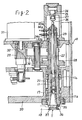
spindle head 10, thespindle 11 rotatably supported by ahousing 20 is formed with a tool receiving tapered bore lla at its lower end and a through bore llb connected to the tapered bore lla. Within the through bore llb, there are received asnap member 21 engageable with apull stud 17 extended from one end of a tool T received in the tapered bore lla, adrawing rod 22 connected at its forward end with thesnap member 21 and projected at its rear end from the rear end of thespindle 11, and a set ofwasher springs 23 drawing thedrawing rod 22 in the rearward direction relative to thespindle 11, in such a manner as to constitute a clamp device for clamping the tool T relative to thespindle 11. In face to face relationship with the rear end of thedrawing rod 22, there is disposed anunclamping cylinder 24 whosepiston rod 25 rotatably supports anabutting member 26 at its forward end through a thrust bearing 27. When thedrawing rod 22 is urged against thesprings 23 through theabutting member 26, the tool T in thespindle 11 is unclamped. Agear member 28 is secured on thespindle 11 and is connected through a shiftabletransmission gear member 30 and adrive gear 29 to anoutput shaft 32 of aspindle drive motor 31 which is mounted on the upper end of thespindle head 10. Thedrive motor 31 is driven at a speed depending upon a rotary speed command applied from a numerical control device NC and also at a predetermined low speed in response to a tool change command, as described later in more detail. - To the rear end of the
spindle 11 are secured first and second dog members 33a, 33b at predetermined angular positions, referred to later in detail. The first and second dog members 33a, 33b cooperates with first andsecond proximity switches 34a, 34b secured to thehousing 20 to generate first and second signals indicating proper timing when a tool T should be inserted into and removed from thespindle 11, respectively. On the front end of thespindle 11 is mounted akey 35 which is engageable with each one of the key-ways 36 formed on aflange portion 37 of a tool T. In order to make engagement between thekey 35 and the key-way 36 without trouble during rotation of thespindle 11, the width ℓ1 of thekey 35 is formed narrower than thewidth 12 of the key-way 36 by several millimeters, as shown in FIGURE 8. - Referring to FIGURE 3 showing a detailed construction of the
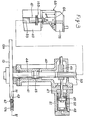
tool change arm 13 and a drive device therefor, asupport shaft 41 is rotatably and axially movably supported by asupport body 40. Thesupport shaft 41 has secured at its lower end thetool change arm 13 which is formed at its opposite ends with a pair ofcircular tool grippers support shaft 41 and engageable with theflange portion 37 of each tool T. In order to prevent a tool T from falling from thetool gripper plunger 43 rotatably supporting anengaging roller 42 at its one end is guided at each end of thetool change arm 13 to be movable in a substantially radial direction and is urged outwardly by a spring, not shown. This spring is calibrated in such a manner that when thetool change arm 13 is rotated to grip or release the tools held in thespindle 11 and the tool socket 16 in its vertical position, theplunger 43 is moved inwardly to allow such grip or release of the tool, and when the tools are held by thetool grippers tool change arm 13, theengaging roller 42 is urged toward the tool T to prevent the tool from falling but to allow frictional rotation of the tool. - The
support shaft 41 is formed at its intermediate portion with apiston 45 slidably received in acylinder 44 formed in thesupport body 40. Selective supply of pressurized fluid into upper and lower cylinder chambers of thecylinder 44 causes thetool change arm 13 to be vertically moved to insert and withdraw the tools T. Thesupport shaft 41 is formed at its upper end with anelongated gear 53 in meshing engagement with arack bar 46. Therack bar 46 is connected through apiston rod 47 with apiston 49 of ahydraulic cylinder 48 capable of positioning at four positions. Thepiston 49 is slidably received in aninner cylinder 50 which is, in turn, slidably received in anouter cylinder 51. When theinner cylinder 50 is moved relative to theouter cylinder 51 with relative movement being restrained between thepiston 49 and theinner cylinder 50, thetool change arm 13 is rotated between a ready position shown in solid lines in FIGURE 1 and a tool grip position shown in phantom lines to grasp or release the tools. When thepiston 49 is moved relative to theinner cylinder 50 which is restrained from movement relative to theouter cylinder 51 at its right or left end position, thetool change arm 13 is rotated 180 degrees to change the tools. - Referring now to FIGURE 4, a
detent pin 55, engageable with the key-way 36 of a tool T, is slidably received in each of thetool grippers spring 56 in the radial direction of the tool T for restricting the rotational movement of the tool T. However, thedetent pin 55 is chamfered at the edges so as to allow the rotation of the tool T when the tool T is forced to rotate by thespindle 11 through the key engagement between thekey 35 and the key-way 36. - Description is now made to a stopping device, shown in FIGURES 3, 5 and 6, for stopping the axial movement of the
tool change arm 13 at a predetermined intermediate position immediately before theflange portion 37 of the tool T comes into contact with thekey 35. To the upper portion of thesupport body 40 is secured asupport bracket 65, as shown in FIGURES 5 and 6 in detail, to which alink holder 66 is secured above thesupport shaft 41. Thelink holder 66 is provided with a fixedpin 67 horizontally secured thereto at the upper portion thereof and a vertically elongated groove 66a formed at the lower portion thereof. The fixedpin 67 rotatably supports one end portion of afirst link 68. Amovable pin 70 horizontally secured to one end portion of asecond link 69 is received slidably in the axial direction of thesupport shaft 41 in the elongated groove 66a. A connectingpin 71 rotatably supports the other end portions of thelinks pin 67 and themovable pin 70 may be varied. Aroller 72, engageable with the top end of thesupport shaft 41, is rotatably supported at the intermediate portion of themovable pin 70. - Accordingly, when the first and
second links support shaft 41 may be moved upward toward the uppermost position where thepiston 45 comes into contact with the upper end wall of thecylinder 44, however, when they are in the straight position, as shown in phantom lines in FIGURE 5, thesupport shaft 41 is prevented from moving upward further from the intermediate position-which is lower than the uppermost position by a predetermined distance S due to the engagement of theroller 72 with the top end of thesupport shaft 41. The intermediate position is adjusted in such a way that theflange portion 37 of the tool T gripped in thetool change arm 13 is apart a predetermined distance 4d from the key 35 of thetool spindle 11, as shown in FIGURE 8. Alimit switch 74 is mounted on thesupport bracket 65 and actuated in cooperation with adog member 73 secured to thesupport shaft 41 in order to confirm that thesupport shaft 41 is stopped at the intermediate position. Further, to thesupport bracket 65 is secured asolenoid 75 having an actuatingrod 76, one end of which is connected through a connectinglink 78 with one end of alink 77 which is secured to thesecond link 69. The other end of thelink 77 is pulled upward by atension spring 79 attached to thesupport bracket 65 so as to tend to straighten the first andsecond links solenoid 75 is actuated to hold theactuating rod 76 at the upper position shown in solid lines in FIGURE 5, the first andsecond links tension spring 79. Therefore, thesolenoid 75 constitutes a releasing device for releasing the above-mentioned stopping operation of the stopping device. - Referring now to FIGURE 7, the
spindle drive motor 31 is controlled to be rotated at a speed depending upon any of the various tools inserted in thespindle 11. When a rotational speed command (S-code) is applied from the numerical control device NC to aregister 80, the speed command is converted by a digital toanalog converter 81 into a corresponding voltage which is, in turn, applied as a speed command voltage to amotor drive circuit 83 through anamplifier 82. The actual rotational speed of thedrive motor 31 is detected by aspeed detector 84, and the detected actual speed is feedbacked to themotor drive circuit 83. Accordingly, the rotational speed of thedrive motor 31 is controlled in such a manner that the detected actual rotational speed becomes equal to the commanded rotational speed. When a d.c. motor is used as thedrive motor 31, a thyristor Leonard device is used as themotor drive circuit 83. When an a.c. motor is used as thedrive motor 31, a variable frequency inverter device is used as themotor drive circuit 83. - In order to perform a tool change operation, it is necessary to reduce a rotational speed of the
spindle 11 from a speed depending upon any of various tools to a predetermined low speed such as several tens rpm. A settingdevice 85 for setting such predetermined low speed command is connected to the digital toanalog converter 81 through a switchingcircuit 86. When the numerical control device NC generates a tool change command M06, the switchingcircuit 86 applies, instead of a rotational speed command set in theregister 80, the predetermined low speed command set in thesetting device 85 to the digital toanalog converter 81. As a result, themotor drive circuit 83 controls the rotation of themotor 31 so as to rotate thespindle 11 at the set low speed. When engagement between the key-way 36 of the tool T and the key 35 is confirmed by a limit switch, not shown, in cooperation with adog member 103 secured to thesupport shaft 41, as shown in FIGURE 3, the switchingcircuit 86 is changed over to cause a rotational speed command set in theregister 80 to be applied to the digital toanalog converter 81, whereby thespindle 11 is rotated at a speed depending upon a tool T inserted therein. - Referring now to FIGURE 9 wherein the
spindle 11 is rotated in a clockwise direction indicated by an arrow, angular positions Pl, P2 indicate the timing when the first andsecond proximity switches 34a, 34b generate the first and second signals in cooperation with the first and second dog members 33a, 33b respectively, and an angular position P0 indicates the timing when the key 35 of thespindle 11 reaches to the corresponding position of the key-way 36 of a tool T. An angular distance #1 between the angular positions Pl and P0 corresponds to the rotational angular range of thespindle 11 while thetool change arm 13 is axially moving the distance Δd from the intermediate stop position in response to the first signal. Similarly, an angular distance θ2 between the angular positions P2 and P0 corresponds to the rotational angular range of thespindle 11 while the tool change arm is moving downwardly in response to the second signal until the key 35 and the key-way 36 are disengaged. - In this embodiment, since the distance Δd is set rather small, the angular distance 02 is larger than the angular distance θ1. It is noted, however, the distance θ1, 92 can be set variously by changing the angular positions of the first and second dog members 33a, 33b.
- The operation of the machine tool with an automatic tool change function according to the present invention will be now described. The
spindle 11 is usually rotated within a wide range from 20 to 3,000 rpm, and theshiftable gear 30 is operated at the intermediate of such range to change the reduction gear ratio. For example, theshiftable gear 30 is shifted to a low speed range when the rotational speed is lower than 1,100 rpm, and to a high speed range when the rotational speed is higher than 1,100 rpm, Accordingly, frequency in use at the low speed range is higher in usual machining operations, so that theshiftable gear 30 is hereunder assumed to be shifted to the low speed range for convenience of description. - Upon completion of a machining operation by a predetermined tool, the
spindle 11 continues to rotate at a high speed depending upon a rotational speed command set in theregister 80. Thespindle head 10 is moved upward to its upper end position for a tool change operation. When the tool change command M06 is generated from the numerical control device NC, the switchingcircuit 86 is changed over to apply a rotational speed command set in thesetting device 85. Accordingly, thedrive motor 31 is applied with an electrical braking torque so as to rotate thespindle 11 at a predetermined low speed suitable for key engagement. Thereafter, thetool change arm 13 is rotated to grip by thetool grippers spindle 11. The unclampingcylinder 24 is subsequently operated to move the drawingrod 22 downwardly against thesprings 23, thereby unclamping the tool T held in thespindle 11. When thespindle 11 is rotated to the predetermined position P2, where thesecond proximity switch 34b is changed from OFF to ON state, pressurized fluid is supplied to the upper chamber of thecylinder 44 to move thetool change arm 13 downwardly, thereby withdrawing the tools T from thespindle 11 and the tool socket 16. The key-way 36 of the tool T is disengaged from the key 35 of thespindle 11 by such withdrawal of the tool T from thespindle 11, whereby rotation of the tool T withdrawn from thespindle 11 is immediately stopped by the grip force of thetool change arm 13. Accordingly, the key-way 36 of the tool T grasped by thetool change arm 13 is maintained at a substantially predetermined angular position, which corresponds to the position of the key-way 36 of each tool T held in the tool socket 16 of the tool magazine 15. - After the
tool change arm 13 is moved to its lower end position, thepiston 49 is moved, with movement of theinner cylinder 50 being restrained, to rotate thetool change arm 13 by 180 degrees. During the withdrawing movement of thetool change arm 13 and the rotation of thetool change arm 13, thesolenoid 75 is caused to be demagnetized to lower theactuating rod 76. As a result, the first andsecond links spring 79, as shown in phantom lines in FIGURE 5, and theroller 72 is caused to extend downwardly by the predetermined length S. After thetool change arm 13 is rotated by 180 degrees, pressurized fluid is supplied to the lower chamber of thecylinder 44 to move thetool change arm 13 upwardly to insert the tool T withdrawn from the tool socket 16 into the tapered bore lla of thespindle 11 and the tool withdrawn from thespindle 11 into the tool socket 16. However, since theroller 72 is in the extended position, the upward movement of thetool change arm 13 is stopped at the intermediate position immediatly before theflange portion 37 of the tool T comes into contact with the key 35 of thetool spindle 11 rotating at the predetermined low speed due to the engagement of the top portion of thesupport shaft 41 with theroller 72. This intermediate stop of thetool change arm 13 is detected by the actuation of thelimit switch 74 with thedog member 73 secured to thesupport shaft 41. Subsequently, when the first proximity switch 34a detects that the key 35 of therotating tool spindle 11 comes into the predetermined position P1 relative to the key-way 36 of the tool T grasped by thetool change arm 13 with its angular position maintained by thedetent pin 55, thesolenoid 75 is actuated to move theactuating rod 76 upward, whereby the first andsecond links spring 79 so as to move theroller 72 upward and permit thesupport shaft 41 to move from the intermediate position. Accordingly, thetool change arm 13 is again moved upward by pressurized fluid applied to thecylinder 44, thereby to make engagement of the key-way 36 of the tool T with the key 35 of thetool spindle 11. The rotation of thespindle 11 is transmitted through the key 35 to the tool T to forcibly rotate the same gripped by thetool gripper 13a of thetool change arm 13. - Simultaneously with this, the tool T which is previously inserted into the
spindle 11 and now gripped by theother tool gripper 13b is returned to the tool socket 16 in such a manner that the key-way 36 of the tool T is engaged with thedetent pin 16a of the tool socket 16 to avoid its rotation. - Accordingly, a large diameter tool with a radially projected cutter is prevented from interference with an adjacent tool on the tool magazine 15. Further, a predetermined one of the two key-
ways 36 is always engaged with the key 35 of the spindle, whereby the position of the tool T relative to thespindle 11 is maintained even after several tool change operations to thereby achieve a precision machining operation. - After the
tool change arm 13 is moved to its upward end position, and the tools T gripped by thetool grippers spindle 11 and the tool socket 16, the key engagement between the key 35 and the key-way 36 is confirmed by the actuation of the limit switch, not shown, with thedog member 103 secured to thesupport shaft 41. The confirmation of key engagement causes theunclamping cylinder 24 to be deactivated to thereby release the urging force of the drawingrod 22. Accordingly, the tool T is clamped on thespindle 11 by means of thesprings 23. Subsequently, thetool change arm 13 is rotated back to its ready position, thereby completing a tool change operation. With the tool change operation being completed, the tool change command is cancelled so that the switchingcircuit 86 renders a command signal from the settingdevice 85 inoperative and a command signal from theregister 80 operative. Thespindle 11 is thus rotated at a high speed depending upon a newly inserted tool for a next machining operation. - In the above-described embodiment, the
tool change arm 13 is used as a tool support device. However, the present invention can be applied to a machine tool wherein tools are directly changed between the tool magazine and the spindle. In such a case, the tool magazine is used as the tool support device. - Further, a stopping device is provided with a link mechanism for stopping the
support shaft 41 and thetool change arm 13 at the intermediate position, and with asolenoid 75 for releasing its stopping operation, however, the present invention is not limited to the embodiment and other device may be used. - Furthermore, in the above-described embodiment, two sets of a dog member and a proximity switch are provided for generating two signals for a tool change operation, however, only one set of a dog member and a proximity switch is necessary if the distance Ad is adjusted to correspond to the length of the key engagement between the key 35 and the key-
way 36 so as to equalize the angular distance θ1 to theangular distance 82. In this case, a signal generated from the set of the dog member and the proximity switch is used to indicate proper timing for both insertion and withdrawal of a tool. - As described above, according to the present invention, a tool change operation is carried out while the spindle is rotated. Therefore, there is no need to provide a device to stop the spindle at a predetermined angular position, as in the conventional apparatus, whereby a tool change time is considerably shortened, resulting in increase of the machining efficiency.
- Further, according to the present invention, a key of a spindle is engaged with a key-way of a tool without sliding contact therebetween, whereby the tool and the key are prevented from being worn or scratched.
- Furthermore, according to the present invention, a tool is removed from the rotating spindle in response to a signal confirming the predetermined angular position of the spindle, whereby the key-way of a tool returned from the spindle to the tool magazine is maintained at a substantially predetermined angular position. These arrangement and control are particularly effective for large sized tools.
- Obviously, numerous modifications and variation of the present invention are possible in light of the above teachings. It is to be understood, therefore, that within the scope of the appended claims, the invention may be practiced otherwise than as specifically described herein.
Claims (9)
Applications Claiming Priority (2)
| Application Number | Priority Date | Filing Date | Title |
|---|---|---|---|
| JP55172248A JPS5796748A (en) | 1980-12-05 | 1980-12-05 | Automatic tool interchange apparatus |
| JP172248/80 | 1980-12-05 |
Publications (2)
| Publication Number | Publication Date |
|---|---|
| EP0053646A2 true EP0053646A2 (en) | 1982-06-16 |
| EP0053646A3 EP0053646A3 (en) | 1983-07-20 |
Family
ID=15938362
Family Applications (1)
| Application Number | Title | Priority Date | Filing Date |
|---|---|---|---|
| EP81101382A Withdrawn EP0053646A3 (en) | 1980-12-05 | 1981-02-25 | Machine tool with automatic tool change function |
Country Status (3)
| Country | Link |
|---|---|
| US (1) | US4414732A (en) |
| EP (1) | EP0053646A3 (en) |
| JP (1) | JPS5796748A (en) |
Cited By (4)
| Publication number | Priority date | Publication date | Assignee | Title |
|---|---|---|---|---|
| US4532693A (en) * | 1983-01-17 | 1985-08-06 | Alfing Kessler Sondermaschinen Gmbh | Tool exchanging apparatus for a machine tool having a plurality of processing spindles |
| FR2650523A1 (en) * | 1989-08-07 | 1991-02-08 | Rafer Sa | AUTOMATIC CHANGE TOOL DISPENSER FOR MACHINE TOOLS AND THE LIKE |
| USRE34556E (en) * | 1985-01-23 | 1994-03-01 | Smith & Nephew Dyonics Inc. | Surgical system for powered instruments |
| US5749885A (en) * | 1995-10-02 | 1998-05-12 | Smith & Nephew, Inc. | Surgical instrument with embedded coding element |
Families Citing this family (17)
| Publication number | Priority date | Publication date | Assignee | Title |
|---|---|---|---|---|
| JPS5882647A (en) * | 1981-11-05 | 1983-05-18 | Yamazaki Mazak Corp | Allocation control method of magazine pocket in machining center |
| US4520550A (en) * | 1983-05-27 | 1985-06-04 | Automated Robotic Systems, Inc. | Robot tool changer |
| US4739044A (en) * | 1985-06-13 | 1988-04-19 | Amgen | Method for derivitization of polynucleotides |
| DE3717016A1 (en) * | 1987-05-21 | 1988-12-08 | Klessmann Ima Norte Maschfab | MACHINE TOOL WITH VERTICAL WORK SPINDLE AND TOOL CHANGE DEVICE |
| US5816987A (en) * | 1996-10-25 | 1998-10-06 | National Science Council | Elliptic trammel mechanism for automatic tool changing apparatus |
| US5954623A (en) * | 1997-10-07 | 1999-09-21 | Davis; Steven E. | Tool changer apparatus and method of automating a machine tool |
| DE10316244B3 (en) * | 2003-04-09 | 2004-07-29 | Siemens Ag | Machine tool spindle device has tension rod displaced axially within hollow spindle head shaft via axial movement of drive shaft via displacement device |
| CN101372146B (en) * | 2007-08-22 | 2012-07-04 | 康准电子科技(昆山)有限公司 | Method for molding plastic rubber piece tridimensional pattern and molding equipment using the method |
| DE202009000790U1 (en) | 2009-01-20 | 2009-03-26 | Schneider Gmbh & Co. Kg | Polishing head and tool change arm for a polishing head |
| JP6078413B2 (en) * | 2013-04-30 | 2017-02-08 | Dmg森精機株式会社 | Tool changing method and machine tool |
| US9221139B2 (en) * | 2013-05-16 | 2015-12-29 | Kugi Tech Corp. | Tool changing mechanism for machine tool |
| JP6411125B2 (en) * | 2014-08-07 | 2018-10-24 | Dmg森精機株式会社 | Tool changer |
| TWI581897B (en) * | 2014-08-21 | 2017-05-11 | Automatic tool changer mechanism | |
| JP6490553B2 (en) * | 2015-09-30 | 2019-03-27 | Dmg森精機株式会社 | Tool changer |
| JP6549646B2 (en) * | 2017-07-06 | 2019-07-24 | ファナック株式会社 | Machine tool and home position correction method |
| DE102018005612A1 (en) | 2017-07-19 | 2019-01-24 | Fanuc Corporation | Guide display method |
| JP6882234B2 (en) * | 2018-07-13 | 2021-06-02 | ファナック株式会社 | Machine Tools |
Citations (6)
| Publication number | Priority date | Publication date | Assignee | Title |
|---|---|---|---|---|
| US3791022A (en) * | 1972-02-02 | 1974-02-12 | Toyoda Machine Works Ltd | Machine tool with automatic tool changing apparatus |
| US3804426A (en) * | 1968-02-05 | 1974-04-16 | Ex Cell O Corp | Machining apparatus with automatic tool changing means |
| US3851562A (en) * | 1972-03-06 | 1974-12-03 | Toyoda Machine Works Ltd | Tool mounting device for a machine tool |
| US3874071A (en) * | 1972-02-25 | 1975-04-01 | Toyoda Machine Works Ltd | Machine tool with automatic tool changing device |
| US3953918A (en) * | 1975-06-25 | 1976-05-04 | Cincinnati Milacron, Inc. | Machine tool with automatic tool changer |
| US4185377A (en) * | 1976-01-29 | 1980-01-29 | Toyoda Machine Works, Ltd. | Machine tool with an automatic tool exchanger |
Family Cites Families (2)
| Publication number | Priority date | Publication date | Assignee | Title |
|---|---|---|---|---|
| US3191260A (en) * | 1961-07-27 | 1965-06-29 | William H Jorgensen | Machine tool turret having multiple tools |
| JPS5742463B2 (en) * | 1974-08-25 | 1982-09-08 |
-
1980
- 1980-12-05 JP JP55172248A patent/JPS5796748A/en active Granted
-
1981
- 1981-02-25 EP EP81101382A patent/EP0053646A3/en not_active Withdrawn
- 1981-04-02 US US06/250,101 patent/US4414732A/en not_active Expired - Fee Related
Patent Citations (6)
| Publication number | Priority date | Publication date | Assignee | Title |
|---|---|---|---|---|
| US3804426A (en) * | 1968-02-05 | 1974-04-16 | Ex Cell O Corp | Machining apparatus with automatic tool changing means |
| US3791022A (en) * | 1972-02-02 | 1974-02-12 | Toyoda Machine Works Ltd | Machine tool with automatic tool changing apparatus |
| US3874071A (en) * | 1972-02-25 | 1975-04-01 | Toyoda Machine Works Ltd | Machine tool with automatic tool changing device |
| US3851562A (en) * | 1972-03-06 | 1974-12-03 | Toyoda Machine Works Ltd | Tool mounting device for a machine tool |
| US3953918A (en) * | 1975-06-25 | 1976-05-04 | Cincinnati Milacron, Inc. | Machine tool with automatic tool changer |
| US4185377A (en) * | 1976-01-29 | 1980-01-29 | Toyoda Machine Works, Ltd. | Machine tool with an automatic tool exchanger |
Cited By (5)
| Publication number | Priority date | Publication date | Assignee | Title |
|---|---|---|---|---|
| US4532693A (en) * | 1983-01-17 | 1985-08-06 | Alfing Kessler Sondermaschinen Gmbh | Tool exchanging apparatus for a machine tool having a plurality of processing spindles |
| USRE34556E (en) * | 1985-01-23 | 1994-03-01 | Smith & Nephew Dyonics Inc. | Surgical system for powered instruments |
| FR2650523A1 (en) * | 1989-08-07 | 1991-02-08 | Rafer Sa | AUTOMATIC CHANGE TOOL DISPENSER FOR MACHINE TOOLS AND THE LIKE |
| EP0412919A1 (en) * | 1989-08-07 | 1991-02-13 | Rafer S.A. | Automatic tool-changing distributor for machine tools and similar |
| US5749885A (en) * | 1995-10-02 | 1998-05-12 | Smith & Nephew, Inc. | Surgical instrument with embedded coding element |
Also Published As
| Publication number | Publication date |
|---|---|
| JPS6258860B2 (en) | 1987-12-08 |
| JPS5796748A (en) | 1982-06-16 |
| EP0053646A3 (en) | 1983-07-20 |
| US4414732A (en) | 1983-11-15 |
Similar Documents
| Publication | Publication Date | Title |
|---|---|---|
| EP0053646A2 (en) | Machine tool with automatic tool change function | |
| EP0044886B1 (en) | Machine tool with automatic tool change function | |
| KR100289138B1 (en) | Automatic tool changer for machine tools | |
| EP0052824A2 (en) | Machine tool with automatic tool change function | |
| EP0890411B1 (en) | Indexing apparatus and method for driving the same for indexing the same | |
| KR20000064921A (en) | Electric chuck of machine tool and its opening / closing method | |
| US3874071A (en) | Machine tool with automatic tool changing device | |
| US4019246A (en) | Machine tool with automatic tool changer | |
| US4887345A (en) | Turret apparatus | |
| EP0337807B1 (en) | Automatic tool changer | |
| US3994061A (en) | Machine tool with an automatic tool changer | |
| US6257109B1 (en) | Automatic lathe and method of controlling same | |
| EP0011710B1 (en) | Machine tool with an automatic tool changer for single tools and multiple spindle toolheads, and a multiple spindle toolhead | |
| US3298098A (en) | Machine tool with tool changer | |
| US4773152A (en) | Automatic tool changer | |
| US4091526A (en) | Machine tool with an automatic tool exchanger | |
| EP0712685B1 (en) | Automatic tool exchanging apparatus for machine tool | |
| US3791022A (en) | Machine tool with automatic tool changing apparatus | |
| US3837070A (en) | Automatic tool change apparatus | |
| KR100401474B1 (en) | Turret tool rest | |
| JP3150753B2 (en) | Tool changer for machine tools | |
| US5121039A (en) | Index control apparatus for tool rest of nc lathe | |
| JPS59156601A (en) | Multiple spindle type lathe | |
| JPH10254520A (en) | Original point returning method for nc control axis | |
| JPS6257457B2 (en) |
Legal Events
| Date | Code | Title | Description |
|---|---|---|---|
| PUAI | Public reference made under article 153(3) epc to a published international application that has entered the european phase |
Free format text: ORIGINAL CODE: 0009012 |
|
| 17P | Request for examination filed |
Effective date: 19810325 |
|
| AK | Designated contracting states |
Designated state(s): DE FR GB NL SE |
|
| RBV | Designated contracting states (corrected) |
Designated state(s): DE FR GB NL SE |
|
| PUAL | Search report despatched |
Free format text: ORIGINAL CODE: 0009013 |
|
| AK | Designated contracting states |
Designated state(s): DE FR GB NL SE |
|
| STAA | Information on the status of an ep patent application or granted ep patent |
Free format text: STATUS: THE APPLICATION HAS BEEN WITHDRAWN |
|
| 18W | Application withdrawn |
Withdrawal date: 19831115 |
|
| RIN1 | Information on inventor provided before grant (corrected) |
Inventor name: SANO, YOSHIKAZU Inventor name: NAKASHIMA, KUNIMICHI Inventor name: TOMITA, TAMAKI |