EP0053923A1 - Seat track fitting - Google Patents
Seat track fitting Download PDFInfo
- Publication number
- EP0053923A1 EP0053923A1 EP81305725A EP81305725A EP0053923A1 EP 0053923 A1 EP0053923 A1 EP 0053923A1 EP 81305725 A EP81305725 A EP 81305725A EP 81305725 A EP81305725 A EP 81305725A EP 0053923 A1 EP0053923 A1 EP 0053923A1
- Authority
- EP
- European Patent Office
- Prior art keywords
- shear pin
- track
- seat
- fitting
- track fitting
- Prior art date
- Legal status (The legal status is an assumption and is not a legal conclusion. Google has not performed a legal analysis and makes no representation as to the accuracy of the status listed.)
- Granted
Links
Images
Classifications
-
- B—PERFORMING OPERATIONS; TRANSPORTING
- B64—AIRCRAFT; AVIATION; COSMONAUTICS
- B64D—EQUIPMENT FOR FITTING IN OR TO AIRCRAFT; FLIGHT SUITS; PARACHUTES; ARRANGEMENTS OR MOUNTING OF POWER PLANTS OR PROPULSION TRANSMISSIONS IN AIRCRAFT
- B64D11/00—Passenger or crew accommodation; Flight-deck installations not otherwise provided for
- B64D11/06—Arrangements of seats, or adaptations or details specially adapted for aircraft seats
- B64D11/0696—Means for fastening seats to floors, e.g. to floor rails
Definitions
- the invention relates to track fittings and particularly to fittings used to attach the rear legs of aircraft passenger seats to slotted seat tracks in the floor of an aircraft.
- Such track fittings typically include a pair of spaced stud portions which are adapted to enter the seat track through wide openings and then be slid fore or aft by a distance equal to one-half the distance between the centres of the studs so they will underlie retaining lip portions on the seat track.
- a flanged shear pin is also mounted on the track fitting and is movable vertically so that it will be wholly above the seat track when the stud portions are dropped into the wide slotted openings in the seat track and can be lowered partially into one of .the wide openings after the stud portions are slid under the lip portions of the seat track by a distance of one-half the distance between a pair of wide openings.
- threaded fastener members which will move one portion of the track fitting relative to other portions such that one or more portions will be forced into tight frictional contact with the seat track.
- the present invention seeks to provide a track fitting which will overcome all of the disadvantages of the hereinabove discussed prior art devices and will provide many previously unavailable advantages.
- One additional advantage is that the actuating lever which actuates the shear pin is preferably formed in a curved manner such that it smoothly recesses into a rearwardly extending portion of a uniquely designed seat leg structure with which the improved track fitting may be used.
- a track fitting for anchoring a seat to a seat track comprising a body portion having a pair of downwardly depending stud portions adapted to underlie retaining lip portions of a seat track, an open area between said stud portions, a flanged shear pin mounted for vertical movement in said open area from a downward operative position in which the flange of the shear pin bears on the top of the seat track to an upward inoperative position in which the shear pin is clear of the seat track, a spring for normally urging said shear pin downwardly and means for raising the shear pin against the urging of said spring, is characterised in that said shear pin raising means comprises a manually actuable lever member having a pair of arms straddling the sides of said body portion, the outer ends of said arms being pivotally attached to said shear pin, a downwardly projecting cam portion intermediate the ends of each arm, a pair of contact portions on said body portion having contact surfaces which are adapted to be progressively engaged
- the body portion has an aperture at its upper forward corner by which it is pivotally pinned to a seat leg member.
- said lever member has an extended curved upper actuator portion by which it is actuated, said pair of arms which straddle the sides of the body portion suitably being pivotally pinned to the shear pin adjacent to the top thereof.
- the cam portion extending from an intermediate point on the lower side of each arm contacts an upper corner of the projection on the body portion and rocks and slides relative to it as the lever actuator portion is moved down so as to lift the shear pin.
- the pinned ends of the arms move over-centre and cause the cam portions to first slide off the projections and then resiliently wedge against and engage a forward facing side of the projection under the force of the shear pin spring which is now substantially fully compressed.
- the shear pin is firmly locked in its upper disengaged position so that the seat can be easily assembled to the seat track and moved so that the stud portions are slid under the lip portions on the seat track to their approximate final position.
- the actuator portion may be lifted to disengage the over-centre locking of the cam portion and permit the shear pin spring to urge the shear pin downwardly into one of the seat track slots as soon as it becomes aligned with it due to further fore or aft movement of the seat.
- Portions of the forward surface of the body portion are desirably formed to cooperate with portions of the seat leg and of a cover for the seat track to permit the track fitting to be preassembled to the seat in such a manner that it will remain generally level as the seat is handled before assembly to the seat track.
- an improved track fitting according to the invention is indicated generally at 10 in its operative relationship with a seat track 12 and a rear seat leg 14 which is affixed to the fitting 10 by a bolt 16.
- the track fitting 10 illustrated is specifically intended for use in an aircraft but its use in other passenger vehicles is not ruled out.
- the track fitting 10 has a body portion 20 which may, for example, be made as a stainless steel investment casting.
- the body portion 20 includes a forward or leading end leg portion 20' and a rearward or trailing end leg portion 20" which are formed at their lower ends so as to include respectively, a forward flanged stud portion 22 and a rearward flanged stud portion 24.
- the stud portions 22, 24 are preferably connected by an integral web portion 26 which is of a limited height and which, in the operative position of the track fitting 10, is accommodated within a recess 28' within a movable shear pin 28 as shown in Figure 6.
- the shear pin is adapted to move vertically in an opening defined between the leg portions 20', 20" and is retained against sidewise movement out of the opening due to its being pivotally mounted to spaced arms 30 which are pinned to the shear pin 28 by a roll pin 32.
- the arms 30 are joined at their other ends either by being welded to an actuating lever member 34 or by being formed integrally therewith.
- a spring 38 is retained within the opening between the leg portions 20', 20" by an anti-rattle fastener member 40 which functions to lock the shear pin 28 downwardly in its operative position shown in Figure 2.
- the shear pin 28 is positioned within an opening 12c ( Figure 7) in the seat track 12 after the stud portions 22, 24 have been first dropped through an adjacent pair of openings 12c and then moved fore or aft one-half the distance between adjacent openings 12c so as to be retained under seat track lip portions 12a, 12b.
- the anti-rattle fastener member 40 To move the track fitting 10 relative to a seat track 12, the anti-rattle fastener member 40 must be unscrewed from its Figure 2 locked position, wherein it bears down on the upper end of the shear pin 28, to the relieved position shown in Figure 3, wherein downward movement of the actuating lever 34 in a rocking movement about a projection 44 on the trailing end leg portion 20" will cause the shear pin 28 to be lifted against the urging of the spring 38.
- a cam portion 46 of each arm 30 which engages the projection 44 will slip down beside the projection as shown in Figure 3 and provide somewhat of an over-centre locking arrangement.
- a leaf spring 50 attached to the actuating lever 34, will contact the body portion 20 and prevent any vibration of the actuating lever 34 from taking place.
- the projection 44 for each arm 30 has an upper generally horizontal contact surface 44a (see Figure 1) and a lower generally horizontal contact surface 44c joined by a generally vertical contact surface 44b. These contact surfaces are progressively engaged by the respective cam portion 46 in a sliding fulcrum fashion when the actuating lever 34 is actuated downwardly.
- the actuating lever 34 is positioned in a recessed area of the rear seat leg 14 when in its operative position and functions as a decorative cover for the recess and the fitting. In the operative position, the actuating lever 34 has no accessible portions which a passenger could actuate to release the fitting. A tool such as a screwdriver would have to be used in the space (see Figure 5) between the top of the actuating lever 34 and the portion of the rear seat leg 14 above it to initiate movement of the actuating lever. However, no movement of the actuating lever 34 can take place until the fastener member 40 is screwed upwardly from the locked position shown in Figure 2, where it contacts the shear pin 28, to the unlocked position shown in Figure 3. This is so, since each arm 30 rocks about its cam portion 46 and has its inner end pinned to the shear pin 28.
- a particular advantage of a track fitting according to the invention is that the track fitting 10 can anchor itself in the seat track 12. With the shear pin 28 lifted, as shown in Figure 3, the track fitting 10 is inserted in a seat track 12 and the stud portions 22, 24 are slid partially under the retaining lip portions 12a, 12b. The actuating lever 34 is then lifted just enough to release the cam portion 46 from locking engagement with the projection 44. As soon as the seat and the track fitting are slid fore or aft, a sufficient amount to permit the shear pin 28 to be aligned with an opening 12c, the force of the spring 38 will snap the shear pin 28 downwardly into the opening 12c and lift the actuating lever 34 to its Figure 2 position.
Landscapes
- Engineering & Computer Science (AREA)
- Aviation & Aerospace Engineering (AREA)
- Seats For Vehicles (AREA)
Abstract
Description
- The invention relates to track fittings and particularly to fittings used to attach the rear legs of aircraft passenger seats to slotted seat tracks in the floor of an aircraft. Such track fittings typically include a pair of spaced stud portions which are adapted to enter the seat track through wide openings and then be slid fore or aft by a distance equal to one-half the distance between the centres of the studs so they will underlie retaining lip portions on the seat track. A flanged shear pin is also mounted on the track fitting and is movable vertically so that it will be wholly above the seat track when the stud portions are dropped into the wide slotted openings in the seat track and can be lowered partially into one of .the wide openings after the stud portions are slid under the lip portions of the seat track by a distance of one-half the distance between a pair of wide openings. To prevent rattling of the track fitting, it is known to provide various types of threaded fastener members which will move one portion of the track fitting relative to other portions such that one or more portions will be forced into tight frictional contact with the seat track. In some track fittings it is possible for the shear pin to be lifted and disengaged even though the anti-rattle fastener member is still engaged. This type of track fitting could permit the seat to appear to be firmly anchored to the seat track, but would, of course, easily fail in a crash situation. The situation is especially serious with respect to those track fittings in which the shear pin is at the rear of the track fitting where it would be accessible to a curious passenger who might lift the shear pin from its detented locked position and leave it in its upper unlocked position. Since the anti-rattle fastener member must be accessible to a seat installer, it is often directed to the rear where it can be unsightly to a passenger or where a separate cover member must be provided.
- The present invention seeks to provide a track fitting which will overcome all of the disadvantages of the hereinabove discussed prior art devices and will provide many previously unavailable advantages. One additional advantage is that the actuating lever which actuates the shear pin is preferably formed in a curved manner such that it smoothly recesses into a rearwardly extending portion of a uniquely designed seat leg structure with which the improved track fitting may be used.
- According to the present invention, a track fitting for anchoring a seat to a seat track (e.g. in the floor of an aircraft) comprising a body portion having a pair of downwardly depending stud portions adapted to underlie retaining lip portions of a seat track, an open area between said stud portions, a flanged shear pin mounted for vertical movement in said open area from a downward operative position in which the flange of the shear pin bears on the top of the seat track to an upward inoperative position in which the shear pin is clear of the seat track, a spring for normally urging said shear pin downwardly and means for raising the shear pin against the urging of said spring, is characterised in that said shear pin raising means comprises a manually actuable lever member having a pair of arms straddling the sides of said body portion, the outer ends of said arms being pivotally attached to said shear pin, a downwardly projecting cam portion intermediate the ends of each arm, a pair of contact portions on said body portion having contact surfaces which are adapted to be progressively engaged by said cam portions in a sliding fulcrum fashion when said lever member is actuated downwardly to lift the shear pin against the force of said spring from its operative position to its inoperative position.
- Suitably the body portion has an aperture at its upper forward corner by which it is pivotally pinned to a seat leg member. Desirably said lever member has an extended curved upper actuator portion by which it is actuated, said pair of arms which straddle the sides of the body portion suitably being pivotally pinned to the shear pin adjacent to the top thereof. Suitably the cam portion extending from an intermediate point on the lower side of each arm contacts an upper corner of the projection on the body portion and rocks and slides relative to it as the lever actuator portion is moved down so as to lift the shear pin. Preferably, as the lever actuator approaches its extreme downward position, the pinned ends of the arms move over-centre and cause the cam portions to first slide off the projections and then resiliently wedge against and engage a forward facing side of the projection under the force of the shear pin spring which is now substantially fully compressed. In this position, the shear pin is firmly locked in its upper disengaged position so that the seat can be easily assembled to the seat track and moved so that the stud portions are slid under the lip portions on the seat track to their approximate final position. At this point, the actuator portion may be lifted to disengage the over-centre locking of the cam portion and permit the shear pin spring to urge the shear pin downwardly into one of the seat track slots as soon as it becomes aligned with it due to further fore or aft movement of the seat. Portions of the forward surface of the body portion are desirably formed to cooperate with portions of the seat leg and of a cover for the seat track to permit the track fitting to be preassembled to the seat in such a manner that it will remain generally level as the seat is handled before assembly to the seat track.
- The invention will now be described, ty way of example, with reference to the accompanying drawing, in which:-
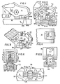
- Figure 1 is a side view illustrating the relationship between a rear seat leg, a seat retaining track and a track fitting according to the present invention;
- Figure 2 is a view similar to Figure 1, but with portions of the leg and seat track broken away;
- Figure 3 is a side view of the track fitting of Figure 2 shown in its track-disengaged condition;
- Figure 4 is a top view of the track fitting and associated leg in the engaged position shown in Figure 1;
- Figure 5 is a view of the track fitting of Figure 1, seen from the right;
- Figure 6 is a view taken on line 6-6 of Figure 2; and
- Figure 7 is a view taken on line 7-7 of Figure 2.
- Referring to Figure 1, an improved track fitting according to the invention is indicated generally at 10 in its operative relationship with a
seat track 12 and arear seat leg 14 which is affixed to thefitting 10 by abolt 16. - The track fitting 10 illustrated is specifically intended for use in an aircraft but its use in other passenger vehicles is not ruled out.
- In Figure 2, portions of the
seat track 12 andseat leg 14 are removed so as to show the relationships between the internal portions of the leg, a track cover 15 (which is fixed to the seat to overlie the track), theseat track 12 and the track fitting 10. The track fitting 10 has abody portion 20 which may, for example, be made as a stainless steel investment casting. Thebody portion 20 includes a forward or leading end leg portion 20' and a rearward or trailingend leg portion 20" which are formed at their lower ends so as to include respectively, a forward flangedstud portion 22 and a rearward flangedstud portion 24. To increase the strength of the track fitting, thestud portions integral web portion 26 which is of a limited height and which, in the operative position of the track fitting 10, is accommodated within a recess 28' within amovable shear pin 28 as shown in Figure 6. As best seen in Figure 2, the shear pin is adapted to move vertically in an opening defined between theleg portions 20', 20" and is retained against sidewise movement out of the opening due to its being pivotally mounted to spacedarms 30 which are pinned to theshear pin 28 by aroll pin 32. Thearms 30 are joined at their other ends either by being welded to an actuatinglever member 34 or by being formed integrally therewith. Aspring 38 is retained within the opening between theleg portions 20', 20" by ananti-rattle fastener member 40 which functions to lock theshear pin 28 downwardly in its operative position shown in Figure 2. In this operative position, theshear pin 28 is positioned within an opening 12c (Figure 7) in theseat track 12 after thestud portions openings 12c and then moved fore or aft one-half the distance betweenadjacent openings 12c so as to be retained under seattrack lip portions 12a, 12b. - To move the track fitting 10 relative to a
seat track 12, theanti-rattle fastener member 40 must be unscrewed from its Figure 2 locked position, wherein it bears down on the upper end of theshear pin 28, to the relieved position shown in Figure 3, wherein downward movement of the actuatinglever 34 in a rocking movement about aprojection 44 on the trailingend leg portion 20" will cause theshear pin 28 to be lifted against the urging of thespring 38. During the lifting movement, acam portion 46 of eacharm 30 which engages theprojection 44 will slip down beside the projection as shown in Figure 3 and provide somewhat of an over-centre locking arrangement. In the operative position shown in Figure 2, aleaf spring 50, attached to the actuatinglever 34, will contact thebody portion 20 and prevent any vibration of the actuatinglever 34 from taking place. - The
projection 44 for eacharm 30 has an upper generallyhorizontal contact surface 44a (see Figure 1) and a lower generally horizontal contact surface 44c joined by a generally vertical contact surface 44b. These contact surfaces are progressively engaged by therespective cam portion 46 in a sliding fulcrum fashion when the actuatinglever 34 is actuated downwardly. - As can be seen in Figures 2 and 3, the
actuating lever 34 is positioned in a recessed area of therear seat leg 14 when in its operative position and functions as a decorative cover for the recess and the fitting. In the operative position, the actuatinglever 34 has no accessible portions which a passenger could actuate to release the fitting. A tool such as a screwdriver would have to be used in the space (see Figure 5) between the top of the actuatinglever 34 and the portion of therear seat leg 14 above it to initiate movement of the actuating lever. However, no movement of the actuatinglever 34 can take place until thefastener member 40 is screwed upwardly from the locked position shown in Figure 2, where it contacts theshear pin 28, to the unlocked position shown in Figure 3. This is so, since eacharm 30 rocks about itscam portion 46 and has its inner end pinned to theshear pin 28. - A particular advantage of a track fitting according to the invention is that the track fitting 10 can anchor itself in the
seat track 12. With theshear pin 28 lifted, as shown in Figure 3, thetrack fitting 10 is inserted in aseat track 12 and thestud portions retaining lip portions 12a, 12b. The actuatinglever 34 is then lifted just enough to release thecam portion 46 from locking engagement with theprojection 44. As soon as the seat and the track fitting are slid fore or aft, a sufficient amount to permit theshear pin 28 to be aligned with an opening 12c, the force of thespring 38 will snap theshear pin 28 downwardly into the opening 12c and lift the actuatinglever 34 to its Figure 2 position. If the actuatinglever 34 is lifted all the way to its upper position before theshear pin 28 is aligned with an opening 12c, it will not be correctly located in its recess in therear seat leg 14 as shown in Figures 2 and 5. This is a safety feature, since it permits one to determine visually that firm locking has not yet taken place. The presence of thefastener member 40 above the top surface of therear seat leg 14 also gives a visual indication that the anti-rattle feature has not yet been engaged. As seen in Figure 2,integral projections body portion 20. These projections cooperate, respectively, with therear seat leg 14 and a tab 15' on thetrack cover 15 to limit rotation of the track fitting 10 relative to therear seat leg 14 and thus enable the track fitting and seat to be easily assembled as a unit to theseat track 12.
Claims (10)
Applications Claiming Priority (2)
| Application Number | Priority Date | Filing Date | Title |
|---|---|---|---|
| US06/214,392 US4396175A (en) | 1980-12-08 | 1980-12-08 | Track fitting |
| US214392 | 1980-12-08 |
Publications (2)
| Publication Number | Publication Date |
|---|---|
| EP0053923A1 true EP0053923A1 (en) | 1982-06-16 |
| EP0053923B1 EP0053923B1 (en) | 1985-03-20 |
Family
ID=22798926
Family Applications (1)
| Application Number | Title | Priority Date | Filing Date |
|---|---|---|---|
| EP81305725A Expired EP0053923B1 (en) | 1980-12-08 | 1981-12-04 | Seat track fitting |
Country Status (4)
| Country | Link |
|---|---|
| US (1) | US4396175A (en) |
| EP (1) | EP0053923B1 (en) |
| JP (1) | JPS6137600Y2 (en) |
| DE (1) | DE3169461D1 (en) |
Cited By (10)
| Publication number | Priority date | Publication date | Assignee | Title |
|---|---|---|---|---|
| DE3232234A1 (en) * | 1982-08-30 | 1984-05-24 | Messerschmitt-Bölkow-Blohm GmbH, 8012 Ottobrunn | QUICK RELEASE ELEMENT FOR RAIL PROFILES |
| GB2153215A (en) * | 1984-01-04 | 1985-08-21 | Unwin Limited C N | Furniture anchorages |
| DE3447178A1 (en) * | 1984-12-22 | 1986-07-03 | Keiper Recaro GmbH & Co, 5630 Remscheid | Aircraft passenger seat |
| EP0327990A2 (en) * | 1988-02-12 | 1989-08-16 | KEIPER RECARO GmbH & Co. | Anchor fitting, in particular for an aircraft passenger seat |
| US5169091A (en) * | 1991-07-12 | 1992-12-08 | Beroth Michael T | Track fastener apparatus and assembly |
| US5230485A (en) * | 1991-01-26 | 1993-07-27 | Deutsche Aerospace Airbus Gmbh | Connector device for securing structural components to each other |
| GB2332142A (en) * | 1997-12-10 | 1999-06-16 | Unwin C N Ltds | Anchorage for vehicle seat |
| EP1790521A1 (en) * | 2005-11-23 | 2007-05-30 | Hermann Schnierle Gesellschaft mit beschränkter Haftung | Adjustable seat support for a passenger seat |
| DE102009057447A1 (en) | 2009-12-09 | 2011-06-16 | Sortimo Speedwave Gmbh | Seat console for a passenger seat |
| FR3001195A1 (en) * | 2013-01-22 | 2014-07-25 | Attax | SYSTEM FOR FIXING AN AIRCRAFT SEAT AND AIRCRAFT SEAT COMPRISING SUCH A SYSTEM |
Families Citing this family (44)
| Publication number | Priority date | Publication date | Assignee | Title |
|---|---|---|---|---|
| US4602756A (en) * | 1984-11-26 | 1986-07-29 | Chatfield Alan M | Instrument fastening system |
| US4723732A (en) * | 1985-09-12 | 1988-02-09 | The Boeing Company | Movable seating system for aircraft |
| US4708549A (en) * | 1986-05-01 | 1987-11-24 | Ancra Corporation | Rattle-proof anchor fitting for securing loads to retainer track |
| US4776533A (en) * | 1987-03-20 | 1988-10-11 | The Jepson Burns Corporation | Aircraft seat track fitting assembly |
| US4911381A (en) * | 1987-12-28 | 1990-03-27 | Simula, Inc. | Energy-absorbing leg assembly for aircraft passenger seats |
| US4867623A (en) * | 1989-02-10 | 1989-09-19 | Aeroquip Corporation | Ring fitting for dunnage track |
| GB9013717D0 (en) * | 1990-06-20 | 1990-08-08 | Rumbold Ltd L A | Adjustable passenger seating arrangement |
| US5203483A (en) * | 1990-11-06 | 1993-04-20 | John A. Bott | Vehicle article carrier |
| US5190198A (en) * | 1991-03-27 | 1993-03-02 | John A. Bott | Vehicle article carrier |
| US5337979A (en) * | 1991-12-18 | 1994-08-16 | Weber Aircraft, Inc. | Track fitting for aircraft seats |
| US5762296A (en) * | 1992-02-03 | 1998-06-09 | Weber Aircraft, Inc. | Pivot for rear seat track fitting |
| US5449132A (en) * | 1992-02-03 | 1995-09-12 | Weber Aircraft, Inc. | Passenger seat rear track fitting |
| US5348264A (en) * | 1993-05-28 | 1994-09-20 | Norco Industries, Inc. | Quick release seat pedestal |
| DE69409456T2 (en) * | 1993-09-14 | 1998-08-06 | Jac Products Inc | Locking system for adjustable luggage rack |
| US5383630A (en) * | 1994-03-17 | 1995-01-24 | Teleflex Incorporated | Main deck quick change cargo system |
| US5826766A (en) * | 1997-03-14 | 1998-10-27 | Jac Products, Inc. | Vehicle article carrier |
| DE19812490C2 (en) * | 1998-03-21 | 2002-03-14 | Daimler Chrysler Ag | Device for releasably attaching a seat, in particular a vehicle seat, to a longitudinal rail |
| US6779696B2 (en) * | 2001-10-05 | 2004-08-24 | Jac Products, Inc. | Article carrier having single sided releasable cross bar |
| DE10341624A1 (en) * | 2003-09-10 | 2005-04-07 | Recaro Aircraft Seating Gmbh & Co. Kg | Seat attachment system |
| US6971826B2 (en) * | 2003-12-23 | 2005-12-06 | Valentine And Company | Trolley and chock assembly |
| DE202004015211U1 (en) * | 2004-09-28 | 2004-12-02 | Allsafe Jungfalk Gmbh & Co. Kg | Device for fixing of object such as aircraft seat on rail by a fitting has retainer supported in relation to sliding component by force accumulator, and connecting element has rotatable element to fix retainer in two height positions |
| WO2006034855A1 (en) * | 2004-09-28 | 2006-04-06 | Allsafe Jungfalk Gmbh & Co.Kg | Device for fixing an object to a rail |
| US7785053B2 (en) * | 2006-03-31 | 2010-08-31 | The Boeing Company | Single tough locking seat fittings and methods |
| US8128326B2 (en) * | 2006-03-31 | 2012-03-06 | The Boeing Company | Apparatus and methods for removably securing payloads in an aircraft |
| US7713009B2 (en) * | 2006-03-31 | 2010-05-11 | The Boeing Company | Apparatus and methods for removably securing payloads in an aircraft |
| US8152101B2 (en) * | 2006-09-12 | 2012-04-10 | Law Sondra F | System and method for integrating handicapped accessible seats into aircraft interior configurations |
| DE102007004554B4 (en) * | 2007-01-30 | 2015-08-27 | Airbus Operations Gmbh | Rail for positioning and locking components and an associated fitting |
| DE202008003772U1 (en) * | 2008-03-18 | 2008-07-03 | Sell Gmbh | Device for detachable floor mounting of cabinets or the like in galleys of aircraft |
| DE102009018487B4 (en) * | 2008-05-02 | 2020-06-18 | Goodrich Corp. | Method and device for securing cargo in an aircraft |
| IT1390898B1 (en) * | 2008-08-04 | 2011-10-19 | Salani | QUICK FIXING MECHANICAL SYSTEM FOR PASSENGER TRANSPORTATION ARMCHAIRS FOR CIVIL AVIATION AIRCRAFT |
| FR2943986A1 (en) * | 2009-04-06 | 2010-10-08 | Antar Daouk | COUPLING DEVICE WITH LONGITUDINAL DISPLACEMENT FACULTY |
| US8376675B2 (en) | 2009-06-16 | 2013-02-19 | Goodrich, Corporation | Moveable tiedown |
| US8602702B2 (en) * | 2009-06-23 | 2013-12-10 | Zodiac Seats Us Llc | Seat track fitting |
| FR2947773B1 (en) * | 2009-07-09 | 2012-01-06 | Attax | SYSTEM FOR ATTACHING A SEAT, FOR EXAMPLE OF AN AIRCRAFT |
| FR2957330B1 (en) * | 2010-03-12 | 2012-04-20 | Attax | AIRCRAFT SEAT ATTACHING SYSTEM |
| FR2959985B1 (en) * | 2010-05-17 | 2013-02-22 | Attax | SYSTEM FOR ATTACHING AN AIRCRAFT SEAT IN A FASTENING RAIL |
| FR2973338B1 (en) * | 2011-03-30 | 2013-05-10 | Attax | SYSTEM FOR FIXING A SEAT, IN PARTICULAR AN AIRCRAFT ON THE SAME |
| DE102012205467A1 (en) | 2012-04-03 | 2013-10-10 | Airbus Operations Gmbh | Device for mounting clamping device in profiled rail to fasten seat in passenger cabin e.g. airplane cabin, has driver brought in engagement with clamping element in form-fit manner, and holding element placing tool for actuation of driver |
| DE102013103435A1 (en) * | 2013-04-05 | 2014-10-09 | Recaro Aircraft Seating Gmbh & Co. Kg | seat attachment |
| DE102014201176A1 (en) | 2014-01-23 | 2015-07-23 | Bishop Gmbh | Aircraft seat fitting |
| US10005558B2 (en) * | 2014-03-28 | 2018-06-26 | Zodiac Seats France | Track fitting for aircraft seats |
| FR3019600B1 (en) * | 2014-04-07 | 2016-05-06 | Attax | SYSTEM FOR FIXING AN OBJECT IN A RAIL OF A SUPPORT |
| JP6630179B2 (en) * | 2015-05-14 | 2020-01-15 | Thk株式会社 | Mobile fixing device for seat |
| CN109502028B (en) * | 2018-12-17 | 2023-10-20 | 航宇救生装备有限公司 | Light quick-release chair leg lock |
Citations (6)
| Publication number | Priority date | Publication date | Assignee | Title |
|---|---|---|---|---|
| US3037812A (en) * | 1958-07-30 | 1962-06-05 | Benjamin F Monroe | Aircraft seat structure |
| US3392954A (en) * | 1964-04-30 | 1968-07-16 | Air France | Slidable seats |
| FR2003987A1 (en) * | 1968-03-15 | 1969-11-14 | Hardman Aerospace | SET OF AIRCRAFT SEATS FOR MOUNTING IN TWO FRONT U-PROFILES REMOTE FROM ONE OF THE OTHER |
| US3620171A (en) * | 1969-12-04 | 1971-11-16 | Ancra Corp | Rattleproof tie-down assembly |
| US3677195A (en) * | 1971-09-03 | 1972-07-18 | Ancra Corp | Anchor fitting for retaining articles in a retainer track |
| US4213593A (en) * | 1979-05-25 | 1980-07-22 | Koehler-Dayton, Inc. | Aircraft seat with concealed locking and releasing mechanism |
Family Cites Families (4)
| Publication number | Priority date | Publication date | Assignee | Title |
|---|---|---|---|---|
| US3570415A (en) * | 1968-12-13 | 1971-03-16 | Boeing Co | Track supported mounting device for aircraft |
| US4064811A (en) * | 1975-12-22 | 1977-12-27 | Copeland Donald R | Quick disconnect anchor |
| US4114947A (en) * | 1977-11-18 | 1978-09-19 | Chas. Olson & Sons | Detachable seat mounting for buses |
| US4277043A (en) * | 1979-05-25 | 1981-07-07 | Koehler-Dayton, Inc. | Locking assembly for aircraft seat |
-
1980
- 1980-12-08 US US06/214,392 patent/US4396175A/en not_active Expired - Lifetime
-
1981
- 1981-12-04 DE DE8181305725T patent/DE3169461D1/en not_active Expired
- 1981-12-04 EP EP81305725A patent/EP0053923B1/en not_active Expired
- 1981-12-07 JP JP1981181202U patent/JPS6137600Y2/ja not_active Expired
Patent Citations (6)
| Publication number | Priority date | Publication date | Assignee | Title |
|---|---|---|---|---|
| US3037812A (en) * | 1958-07-30 | 1962-06-05 | Benjamin F Monroe | Aircraft seat structure |
| US3392954A (en) * | 1964-04-30 | 1968-07-16 | Air France | Slidable seats |
| FR2003987A1 (en) * | 1968-03-15 | 1969-11-14 | Hardman Aerospace | SET OF AIRCRAFT SEATS FOR MOUNTING IN TWO FRONT U-PROFILES REMOTE FROM ONE OF THE OTHER |
| US3620171A (en) * | 1969-12-04 | 1971-11-16 | Ancra Corp | Rattleproof tie-down assembly |
| US3677195A (en) * | 1971-09-03 | 1972-07-18 | Ancra Corp | Anchor fitting for retaining articles in a retainer track |
| US4213593A (en) * | 1979-05-25 | 1980-07-22 | Koehler-Dayton, Inc. | Aircraft seat with concealed locking and releasing mechanism |
Cited By (18)
| Publication number | Priority date | Publication date | Assignee | Title |
|---|---|---|---|---|
| DE3232234A1 (en) * | 1982-08-30 | 1984-05-24 | Messerschmitt-Bölkow-Blohm GmbH, 8012 Ottobrunn | QUICK RELEASE ELEMENT FOR RAIL PROFILES |
| GB2153215A (en) * | 1984-01-04 | 1985-08-21 | Unwin Limited C N | Furniture anchorages |
| DE3447178A1 (en) * | 1984-12-22 | 1986-07-03 | Keiper Recaro GmbH & Co, 5630 Remscheid | Aircraft passenger seat |
| EP0327990A2 (en) * | 1988-02-12 | 1989-08-16 | KEIPER RECARO GmbH & Co. | Anchor fitting, in particular for an aircraft passenger seat |
| DE3804354A1 (en) * | 1988-02-12 | 1989-08-24 | Keiper Recaro Gmbh Co | CONNECTING DEVICE, IN PARTICULAR FOR AIRCASE SEATS |
| US4932816A (en) * | 1988-02-12 | 1990-06-12 | Keiper Recaro Gmbh & Co. | Connecting device for aircraft seats and the like |
| EP0327990A3 (en) * | 1988-02-12 | 1990-07-04 | Keiper Recaro Gmbh & Co. | Anchor fitting, in particular for an aircraft passenger seat |
| US5230485A (en) * | 1991-01-26 | 1993-07-27 | Deutsche Aerospace Airbus Gmbh | Connector device for securing structural components to each other |
| US5169091A (en) * | 1991-07-12 | 1992-12-08 | Beroth Michael T | Track fastener apparatus and assembly |
| GB2332142A (en) * | 1997-12-10 | 1999-06-16 | Unwin C N Ltds | Anchorage for vehicle seat |
| GB2332142B (en) * | 1997-12-10 | 2001-09-12 | Unwin C N Ltd | Improvements relating to furniture anchorages |
| EP1790521A1 (en) * | 2005-11-23 | 2007-05-30 | Hermann Schnierle Gesellschaft mit beschränkter Haftung | Adjustable seat support for a passenger seat |
| DE102009057447A1 (en) | 2009-12-09 | 2011-06-16 | Sortimo Speedwave Gmbh | Seat console for a passenger seat |
| EP2340963A1 (en) | 2009-12-09 | 2011-07-06 | Sortimo Speedwave GmbH | Seat console for a passenger seat |
| DE102009057447B4 (en) | 2009-12-09 | 2018-10-04 | Sortimo Speedwave Gmbh | Seat console for a passenger seat |
| FR3001195A1 (en) * | 2013-01-22 | 2014-07-25 | Attax | SYSTEM FOR FIXING AN AIRCRAFT SEAT AND AIRCRAFT SEAT COMPRISING SUCH A SYSTEM |
| WO2014114680A1 (en) * | 2013-01-22 | 2014-07-31 | Attax | System for securing an aircraft seat and aircraft seat comprising such a system |
| US9592915B2 (en) | 2013-01-22 | 2017-03-14 | Attax | System for securing an aircraft seat and aircraft seat comprising such a system |
Also Published As
| Publication number | Publication date |
|---|---|
| DE3169461D1 (en) | 1985-04-25 |
| US4396175A (en) | 1983-08-02 |
| EP0053923B1 (en) | 1985-03-20 |
| JPS6137600Y2 (en) | 1986-10-30 |
| JPS57128599U (en) | 1982-08-11 |
Similar Documents
| Publication | Publication Date | Title |
|---|---|---|
| EP0053923A1 (en) | Seat track fitting | |
| US4213593A (en) | Aircraft seat with concealed locking and releasing mechanism | |
| US5997069A (en) | Removable vehicle seat assembly | |
| US4277043A (en) | Locking assembly for aircraft seat | |
| US6629710B1 (en) | Interlocking device and anchoring system | |
| US4449875A (en) | Seat back mounting system | |
| JP4480714B2 (en) | Lock mechanism for vehicle seat | |
| US5286076A (en) | Seat slide device | |
| EP0767754B1 (en) | Container clamping device | |
| US6079688A (en) | Attachment of a lock to a slide section of an automobile vehicle seat | |
| JP2007534542A (en) | Floor latch mechanism | |
| US7264293B2 (en) | Device for connecting a vehicle seat to a vehicle floor | |
| US20030034654A1 (en) | Latch device for securing cargo containers | |
| US4416467A (en) | Towing couplings | |
| US3802356A (en) | Lock pin mechanism | |
| US4823436A (en) | Two-part connecting fixture for furniture which includes a sprung-detent locking lever | |
| GB1580953A (en) | Coupling hooks | |
| EP0068723B1 (en) | Hand control valve | |
| EP0420684B1 (en) | Latch assemblies for vehicle bonnets | |
| US4795191A (en) | Device for automatically adjusting and locking the height of a deflection fitting of a safety belt in vehicles | |
| JP2002516782A (en) | Lock device | |
| US4632426A (en) | Installation for adjusting a hinge point of a vehicle safety belt | |
| JPS5923621Y2 (en) | Interlocking wire attachment structure of lock mechanism in seat slide device | |
| JPH021142Y2 (en) | ||
| JPS643695Y2 (en) |
Legal Events
| Date | Code | Title | Description |
|---|---|---|---|
| PUAI | Public reference made under article 153(3) epc to a published international application that has entered the european phase |
Free format text: ORIGINAL CODE: 0009012 |
|
| AK | Designated contracting states |
Designated state(s): BE DE FR GB IT |
|
| 17P | Request for examination filed |
Effective date: 19820903 |
|
| ITF | It: translation for a ep patent filed |
Owner name: MODIANO & ASSOCIATI S.R.L. |
|
| RAP1 | Party data changed (applicant data changed or rights of an application transferred) |
Owner name: PTC AEROSPACE INC. |
|
| GRAA | (expected) grant |
Free format text: ORIGINAL CODE: 0009210 |
|
| AK | Designated contracting states |
Designated state(s): BE DE FR GB IT |
|
| REF | Corresponds to: |
Ref document number: 3169461 Country of ref document: DE Date of ref document: 19850425 |
|
| ET | Fr: translation filed | ||
| PLBE | No opposition filed within time limit |
Free format text: ORIGINAL CODE: 0009261 |
|
| STAA | Information on the status of an ep patent application or granted ep patent |
Free format text: STATUS: NO OPPOSITION FILED WITHIN TIME LIMIT |
|
| 26N | No opposition filed | ||
| ITTA | It: last paid annual fee | ||
| PGFP | Annual fee paid to national office [announced via postgrant information from national office to epo] |
Ref country code: GB Payment date: 19941128 Year of fee payment: 14 |
|
| PGFP | Annual fee paid to national office [announced via postgrant information from national office to epo] |
Ref country code: BE Payment date: 19941209 Year of fee payment: 14 |
|
| PGFP | Annual fee paid to national office [announced via postgrant information from national office to epo] |
Ref country code: FR Payment date: 19941215 Year of fee payment: 14 |
|
| PGFP | Annual fee paid to national office [announced via postgrant information from national office to epo] |
Ref country code: DE Payment date: 19950124 Year of fee payment: 14 |
|
| PG25 | Lapsed in a contracting state [announced via postgrant information from national office to epo] |
Ref country code: GB Effective date: 19951204 |
|
| PG25 | Lapsed in a contracting state [announced via postgrant information from national office to epo] |
Ref country code: BE Effective date: 19951231 |
|
| BERE | Be: lapsed |
Owner name: PTC AEROSPACE INC. Effective date: 19951231 |
|
| GBPC | Gb: european patent ceased through non-payment of renewal fee |
Effective date: 19951204 |
|
| PG25 | Lapsed in a contracting state [announced via postgrant information from national office to epo] |
Ref country code: FR Effective date: 19960830 |
|
| PG25 | Lapsed in a contracting state [announced via postgrant information from national office to epo] |
Ref country code: DE Effective date: 19961001 |
|
| REG | Reference to a national code |
Ref country code: FR Ref legal event code: ST |