EP0054878A2 - Suction control device for an endoscope - Google Patents
Suction control device for an endoscope Download PDFInfo
- Publication number
- EP0054878A2 EP0054878A2 EP81110416A EP81110416A EP0054878A2 EP 0054878 A2 EP0054878 A2 EP 0054878A2 EP 81110416 A EP81110416 A EP 81110416A EP 81110416 A EP81110416 A EP 81110416A EP 0054878 A2 EP0054878 A2 EP 0054878A2
- Authority
- EP
- European Patent Office
- Prior art keywords
- cylinder
- engaging portion
- control device
- outer cylinder
- space
- Prior art date
- Legal status (The legal status is an assumption and is not a legal conclusion. Google has not performed a legal analysis and makes no representation as to the accuracy of the status listed.)
- Granted
Links
Images


Classifications
-
- A—HUMAN NECESSITIES
- A61—MEDICAL OR VETERINARY SCIENCE; HYGIENE
- A61M—DEVICES FOR INTRODUCING MEDIA INTO, OR ONTO, THE BODY; DEVICES FOR TRANSDUCING BODY MEDIA OR FOR TAKING MEDIA FROM THE BODY; DEVICES FOR PRODUCING OR ENDING SLEEP OR STUPOR
- A61M1/00—Suction or pumping devices for medical purposes; Devices for carrying-off, for treatment of, or for carrying-over, body-liquids; Drainage systems
- A61M1/71—Suction drainage systems
- A61M1/74—Suction control
- A61M1/741—Suction control with means for varying suction manually
- A61M1/7411—Suction control with means for varying suction manually by changing the size of a vent
Definitions
- This invention relates to a suction control device for an endoscope adapted to suction, air and water feeding, insertion of forceps or other treatment appliances, etc., by means of a channel.
- a suction control device of an endoscope is used for removing mucus, waste, etc., from the body cavity by suction.
- a suction control device is so designed as to be able to be also used for insertion of a treatment appliance and injection of a medical fluid into the body cavity.
- numeral 1 designates an outer cylinder which has its peripheral wall connected with a suction be 2 and its lower end with a channel of the Disposed in the outer cylinder 1 is a guide 5 which consists of a first cylinder portion 3 second cylinder portion 4 with its lower end screwed in the upper end of the first cylinder portion 3, defining a space portion 6 between these two cylirders.
- a slide cylinder 7 is fitted in the guide cylinder 5, and is elastically held by means of a compression spring 8 interposed between the outer peripheral surface of the slide cylinder 7 and the inner peripheral surface of the guide cylinder 5.
- a support coupled with the lower end of the slide cylinder 7 by means of a coupling cylinder 9.
- Held in the support -cylinder 10 is a slider-12 having a central communication hole 11 through which a treatment appliance is passed. Further, a communication hole 13 connecting the space portion 6 with the interior of the guide cylinder 5 is bored through the peripheral wall of the first cylinder portion 3 below the slider 12.
- a cap 14 is fitted on the top of the outer cylinder 1. The cap 14 is provided with a holding hole 15 fitted airtightly with the upper end portion of the guide cylinder 5 and an air hole 16 for connecting the space portion 6 with the open air.
- both the holding hole 15 and the air hole 16 are blocked up with a finger. Then, a sucking force in the suction tube 2, having so far been sucking the open air through the air hole 16 and the space portion 6, acts on the interior of the body cavity through the channel, as indicated by arrow a in Fig. 1. As a result, the mucus or waste in the body cavity is sucked into the suction tube 2.
- the appliance is inserted into the channel through the slide cylinder 7 and the communication hole 11 of the slider 12, and the air hole 16 is blocked up with a finger.
- the three cylinders i.e., the outer cylinder 1, the guide cylinder 5, and the slide cylinder 7, are required for the versatility of the device, and moreover the spring 8 need be interposed between the guide cylinder 5 and the slide cylinder 7.
- the number of components required is increased, and the assembly work is complicated to result in an increase in cost as well as a reduction in productivity.
- the slider 12 to block up the communication hole 13 at liquid feeding is slidably fitted in the guide cylinder 5, it is impossible securely to seal the sliding surface of the slider 12. Accordingly, part of the liquid delivered from the injector may be sucked through the space portion 6 into the suction tube 2, prohibiting satisfactory feeding of the liquid into the body cavity.
- the object of this-invention is to provide a suction control device for an endoscope using fewer cylinders for simplified construction, and capable of secure disconnection of the channel side from the suction tube side at liquid feeding without the use of any sliding surface.
- the endoscope comprises a control section 21 and an insertion section 22 connected with the control section 21 at the proximal end.
- the control section 21 is provided with an eyepiece portion 23, a control knob 24 for bending the distal end portion of the insertion section 22, a light guide cable 25 connected with a light supply unit (not shown), and a suction control device 26.
- a channel 27 extends from the control section 21 to the distal end of the insertion section 22.
- the aforesaid suction control device 26 is constructed as shown in Figs. 3 and 4. From the . control section 21 of the endoscope protrudes an integrally formed support cylinder 28 which communicates by means of the control section 21 with the channel 27 opening at the distal end of the insertion section 22 and has an open end. Fitted in the support cylinder 28 is a first cylinder body 32 having a small-diameter portion 29 and a large-diameter portion 30 coupled by means of a taper portion 31 and opening at the lower or inner end. The lower end portion of the small-diameter portion 29 of the first cylinder body 32 is inserted in the channel 27 and coupled airtightly therewith by means of an 0-ring 33.
- a suction tube 35 is connected with the peripheral wall of the large-diameter portion 30 of the first cylinder body 32 by means of a connector 34.
- the other end of the suction tube 35 communicates with a suction unit 36 shown in Fig. 2.
- Stoppers 37 and 38 protrude from the outer periphery of the upper end of the support cylinder 28 and from the outer peripheral wall of the first cylinder body 32 near the top portion thereof, respectively.
- the first cylinder body 32 is removably fixed to the support cylinder 28 by means of a bayonet ring 39 which engages the stoppers 37 and 38.
- a pressing cylinder 42 with a pressing flange 40 and a fitting flange 41 at both ends is screwed on the outer periphery of the upper end portion of the first cylinder body 32. Pressed by the pressing flange 40 of the pressing cylinder 42, the bayonet ring 39 is kept from loosening.
- the pressing cylinder 42 is crowned with a cap 43 formed of an elastic material, such as rubber and synthetic resin, with an annular fitting groove 44 in the inner peripheral surface of the cap 43 fitted on the fitting flange 41.
- the inner peripheral surface of the cap 43 is connected withe the outer peripheral edge of an annular coupling piece 45 capable of expansion and contraction, as well as of elastic deformation.
- the inner peripheral edge of the coupling piece 45 is connected with the upper end of a second cylinder body 46 which forms an inner cylinder.
- the coupling piece 45 and- the second cylinder body 46 are formed integrally with the cap 43 out of an elastic material.
- the second cylinder body 46 is supported on the outer cylinder 60 by means of the coupling piece 45, and is normally urged toward the second position of Fig. 3 by the elastic force of the coupling piece 45.
- the second cylinder body 46 has at the upper end an opening and at the lower end a narrow communication hole 54 through which a forceps-53 as a treatment appliance, as shown in Fig. 6, is passed tight.
- An annular space portion 47 is defined between the outer peripheral surface of the second cylinder body 46 and the inner peripheral surface of the large-diameter portion 30 of the first cylinder body 32. The space portion 47 is blocked up at the top by the coupling piece 45 to be cut off from the atmosphere.
- Formed in the cap 43 is a communication hole 48 extending from the top of the cap 43 to that part of the space portion 47 between the coupling piece 45 and the opening of the suction tube 35 and connecting the space portion 47 with the atmosphere.
- the second cylinder body 46 is provided, on the inner peripheral surface of its upper end portion, with a step portion 51 in which a distal taper portion 50 of an injector 49 as shown in Fig. 7 is fitted. From the inner peripheral surface of the step portion 51 protrudes an annular projection 52 which is to press on the taper portion 50 to hold the same.
- a first rugged ring 55 as an engaging member formed on the outer peripheral surface of the lower end portion of the second cylinder body 46 is to be fitted elastically and airtightly in a second rugged ring 56 as another engaging member formed on the taper surface of the taper portion 31 of the first cylinder body 32 when the second cylinder body 46 is disposed by elastic deformation of the coupling piece 45, as shown in Fig. 7.
- the first and second rugged rings 55 and 56 are so designed as to be able to be disengaged from each other with a smaller force than a pulling force needed to remove the pressure contact between the taper 50 of the injector 49 and the projection 52. Therefore, the second rugged ring 56 can be disengaged from the first rugged ring 55 to restore the second cylinder body 46 to the second position before the taper portion 50 of the injector 49 is removed from the step portion 51.
- the forceps 53 When using the forceps 53, moreover, the forceps 53 is inserted into the top opening portion of the second cylinder body 46, passed through the communication hole 54 of the second cylinder body 46, and then led into the channel 27, as shown in Fig. 6. In this state, the forceps 53 is fitted airtightly in the communication hole 54, so that the space portion 47 is prohibited from communicating with the atmosphere by means of the second cylinder body 46.
- the communication between the space portion 47 and the atmosphere may be cut off to allow the suction of mucus or waste from the body cavity by blocking up only the communication hole 48 of the cap 43 with a finger.
- the distal taper portion 50 of the injector 49 is fitted in the step portion 51 of the second cylinder body 46, as shown in Fig. 7.
- the injector 49 is then pushed in to elastically deform and extend the coupling piece 45, thereby driving the second cylinder body 46 deep into the first cylinder body 32, the first rugged ring 55 on the outer peripheral surface of the lower end portion of the. second cylinder body 46 is fitted in the second rugged ring 56 on the taper surface of the taper portion 31 of the first cylinder body 32 to cut off thoroughly the communication between the channel 27 and the space portion 47. Accordingly, if the liquid is caused to run out of the injector 49 in this state, then it will securely be introduced into the body cavity through the channel 27 without being affected by the sucking force from the suction tube 35.
- the communication between the channel 27 and the space portion 47 communicating with the suction tube 35 can securely be cut off by displacing the second cylinder body 46, which is movably held in the first cylinder body 32, to couple the first and second rugged rings 55 and 56 by press fit.
- the structure of the device may be simplified to facilitate and secure overall cleaning, and to prohibit the sucking force from the suction tube 35 from leaking to the channel side at liquid feeding to cause the liquid to be sucked into the suction tube 35.
- a step portion 65 is formed on a taper portion 31 of a first cylinder body 32.
- the bottom of the step portion 65 has a taper surface 56 which, declined toward the central axis of the cylinder body 32, forms the second engaging portion.
- the support cylinder 28 may be used as the first-cylinder body.
- the second cylinder body 46 is formed integrally with the cap 43, connected therewith by means of the coupling piece 45. It is to be understood, however, that a device with the same -function of the above-mentioned embodiment may be obtained without integrally forming those members.
- the coupling member is formed of a member capable of expansion and contraction, as well as of elastic deformation.
- the- coupling member may be formed of a member having only one of those properties.
- Such member may, for example, be a bellows connected with the outer and inner cylinders at the outer and inner peripheral edges, respectively.
- a suction control device with a double-cylinder construction including outer and inner cylinders simplified as compared with the conventional triple-cylinder construction despite the same function. Accordingly, the number of components used in the device can be reduced, and overall cleaning of the device can securely be performed with ease.
- the press-fit engagement between the engaging portions on the outer and inner cylinders disconnects the channel side securely from the suction tube side, so that the liquid will never be sucked into the -suction tube.
Abstract
Description
- This invention relates to a suction control device for an endoscope adapted to suction, air and water feeding, insertion of forceps or other treatment appliances, etc., by means of a channel.
- In general, a suction control device of an endoscope is used for removing mucus, waste, etc., from the body cavity by suction. Such a suction control device, however, is so designed as to be able to be also used for insertion of a treatment appliance and injection of a medical fluid into the body cavity.
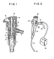
- Conventionally, the suction control device of this type is constructed as shown in Fig. 1. In Fig. 1,
numeral 1 designates an outer cylinder which has its peripheral wall connected with a suction be 2 and its lower end with a channel of theDisposed in the
outer cylinder 1 is aguide 5 which consists of a
first cylinder portion 3
second cylinder portion 4 with its lower end screwed in the upper end of thefirst cylinder portion 3, defining a space portion 6 between these two cylirders. Aslide cylinder 7 is fitted in theguide cylinder 5, and is elastically held by means of acompression spring 8 interposed between the outer peripheral surface of theslide cylinder 7 and the inner peripheral surface of theguide cylinder 5. A supportcoupled with the lower end of the
slide cylinder 7 by means of a coupling cylinder 9. Held in the support -cylinder 10 is a slider-12 having a central communication hole 11 through which a treatment appliance is passed. Further, acommunication hole 13 connecting the space portion 6 with the interior of theguide cylinder 5 is bored through the peripheral wall of thefirst cylinder portion 3 below theslider 12. A cap 14 is fitted on the top of theouter cylinder 1. The cap 14 is provided with aholding hole 15 fitted airtightly with the upper end portion of theguide cylinder 5 and anair hole 16 for connecting the space portion 6 with the open air. - In sucking mucus or waste from a body cavity, both the
holding hole 15 and theair hole 16 are blocked up with a finger. Then, a sucking force in the suction tube 2, having so far been sucking the open air through theair hole 16 and the space portion 6, acts on the interior of the body cavity through the channel, as indicated by arrow a in Fig. 1. As a result, the mucus or waste in the body cavity is sucked into the suction tube 2. In making both treatment with use of the treatment appliance and suction at the same time, the appliance is inserted into the channel through theslide cylinder 7 and the communication hole 11 of theslider 12, and theair hole 16 is blocked up with a finger. In liquid feeding, moreover, the distal end portion of an injector is fitted in theslide tube 7, and theslide tube 7 is pushed and slidden against the restoring force of thespring 8 to cause thecommunication hole 13 to be blocked up by theslider 12 which shifts its position together with theslide cylinder 7. Then, the interior of theguide cylinder 5 is cut off from the space portion 6 to allow a liquid to be fed from the injector into the body cavity through the channel. - In the prior art suction control device of the above-mentioned construction, however, the three cylinders, i.e., the
outer cylinder 1, theguide cylinder 5, and theslide cylinder 7, are required for the versatility of the device, and moreover thespring 8 need be interposed between theguide cylinder 5 and theslide cylinder 7. Thus, the number of components required is increased, and the assembly work is complicated to result in an increase in cost as well as a reduction in productivity. Since theslider 12 to block up thecommunication hole 13 at liquid feeding is slidably fitted in theguide cylinder 5, it is impossible securely to seal the sliding surface of theslider 12. Accordingly, part of the liquid delivered from the injector may be sucked through the space portion 6 into the suction tube 2, prohibiting satisfactory feeding of the liquid into the body cavity. Moreover, 'the aforesaid complicated construction makes it impossible to wash out mucus or waste part of which would inevitably penetrate to the region of thespring 8 and its vicinities through the gap between the respective sliding surfaces of theguide cylinder 5 and thesupport cylinder 10 at the suction of such mucus or waste from the body cavity. - The object of this-invention is to provide a suction control device for an endoscope using fewer cylinders for simplified construction, and capable of secure disconnection of the channel side from the suction tube side at liquid feeding without the use of any sliding surface.
- This invention can be more fully understood from the following detailed description when taken in conjunction with the accompanying drawings, in which:
- Fig. 1 is a sectional view of a prior art suction control device for an endoscope;
- Figs. 2 to 7 show a suction control device of an endoscope according to an embodiment of this invention, in which Fig. 2 is a general perspective view of the endoscope, Fig. 3 is a sectional-view of the suction control device, Fig. 4 is a plan view of a cap, Fig. 5 is a partially broken side view of the device illustrating a sucking operation. Fig. 6 is a sectional view of the device illustrating a forceps operation, and Fig. 7 is a sectional view of the device illustrating a liquid feeding operation; and
- Fig. 8 is a sectional view similar to Fig. 3 showing a modification of engaging portions.
- Now there will be described a suction control device of an endoscope according to an embodiment of this invention with reference to the accompanying drawings. As shown in Fig. 2, the endoscope comprises a
control section 21 and aninsertion section 22 connected with thecontrol section 21 at the proximal end. Thecontrol section 21 is provided with aneyepiece portion 23, acontrol knob 24 for bending the distal end portion of theinsertion section 22, alight guide cable 25 connected with a light supply unit (not shown), and asuction control device 26. In theinsertion section 22, achannel 27 extends from thecontrol section 21 to the distal end of theinsertion section 22. - The aforesaid
suction control device 26 is constructed as shown in Figs. 3 and 4. From the .control section 21 of the endoscope protrudes an integrally formedsupport cylinder 28 which communicates by means of thecontrol section 21 with thechannel 27 opening at the distal end of theinsertion section 22 and has an open end. Fitted in thesupport cylinder 28 is afirst cylinder body 32 having a small-diameter portion 29 and a large-diameter portion 30 coupled by means of ataper portion 31 and opening at the lower or inner end. The lower end portion of the small-diameter portion 29 of thefirst cylinder body 32 is inserted in thechannel 27 and coupled airtightly therewith by means of an 0-ring 33. One end of asuction tube 35 is connected with the peripheral wall of the large-diameter portion 30 of thefirst cylinder body 32 by means of aconnector 34. The other end of thesuction tube 35 communicates with asuction unit 36 shown in Fig. 2. -
Stoppers support cylinder 28 and from the outer peripheral wall of thefirst cylinder body 32 near the top portion thereof, respectively. Thefirst cylinder body 32 is removably fixed to thesupport cylinder 28 by means of abayonet ring 39 which engages thestoppers cylinder 42 with apressing flange 40 and afitting flange 41 at both ends is screwed on the outer periphery of the upper end portion of thefirst cylinder body 32. Pressed by thepressing flange 40 of thepressing cylinder 42, thebayonet ring 39 is kept from loosening. Thepressing cylinder 42 is crowned with acap 43 formed of an elastic material, such as rubber and synthetic resin, with anannular fitting groove 44 in the inner peripheral surface of thecap 43 fitted on thefitting flange 41. -

- The inner peripheral surface of the
cap 43 is connected withe the outer peripheral edge of anannular coupling piece 45 capable of expansion and contraction, as well as of elastic deformation. The inner peripheral edge of thecoupling piece 45 is connected with the upper end of asecond cylinder body 46 which forms an inner cylinder. Preferably, thecoupling piece 45 and- thesecond cylinder body 46 are formed integrally with thecap 43 out of an elastic material. The second cylinder-body 46 is inserted coaxially in theouter cylinder 60 so as to have its lower end located inside in theouter cylinder 60 so as to have its lower end located inside theouter cylinder 60 and to be able to move =axially between a first position on the lower end side of theouter cylinder 60 and a second position, as shown in Fig. 3, on the upper end side of theouter cylinder 60. Thesecond cylinder body 46 is supported on theouter cylinder 60 by means of thecoupling piece 45, and is normally urged toward the second position of Fig. 3 by the elastic force of thecoupling piece 45. Thesecond cylinder body 46 has at the upper end an opening and at the lower end anarrow communication hole 54 through which a forceps-53 as a treatment appliance, as shown in Fig. 6, is passed tight. Anannular space portion 47 is defined between the outer peripheral surface of thesecond cylinder body 46 and the inner peripheral surface of the large-diameter portion 30 of thefirst cylinder body 32. Thespace portion 47 is blocked up at the top by thecoupling piece 45 to be cut off from the atmosphere. Formed in thecap 43 is acommunication hole 48 extending from the top of thecap 43 to that part of thespace portion 47 between thecoupling piece 45 and the opening of thesuction tube 35 and connecting thespace portion 47 with the atmosphere. - The
second cylinder body 46 is provided, on the inner peripheral surface of its upper end portion, with astep portion 51 in which adistal taper portion 50 of aninjector 49 as shown in Fig. 7 is fitted. From the inner peripheral surface of thestep portion 51 protrudes anannular projection 52 which is to press on thetaper portion 50 to hold the same. A firstrugged ring 55 as an engaging member formed on the outer peripheral surface of the lower end portion of thesecond cylinder body 46 is to be fitted elastically and airtightly in a secondrugged ring 56 as another engaging member formed on the taper surface of thetaper portion 31 of thefirst cylinder body 32 when thesecond cylinder body 46 is disposed by elastic deformation of thecoupling piece 45, as shown in Fig. 7. The first and secondrugged rings taper 50 of theinjector 49 and theprojection 52. Therefore, the secondrugged ring 56 can be disengaged from the firstrugged ring 55 to restore thesecond cylinder body 46 to the second position before thetaper portion 50 of theinjector 49 is removed from thestep portion 51. - Now there will be described the operation of the above-mentioned construction. First, when the
suction unit 36 is actuated in the state shown in Fig. 3, a sucking force is produced in thesuction tube 35. Since the atmosphere is sucked into thesuction tube 35 through thecommunication hole 48 and thespace portion 47, however, the sucking force is preventer from acting on the interior of a body cavity through thechannel 27. In sucking mucus or waste from the body cavity, the whole upper portion of thecap 43, i.e., thecommunication hole 48, and the top opening of thesecond cylinder body 46 are blocked up with an operator's finger, as shown in Fig. 5. Then, the communication between thespace portion 47 and the atmosphere is cut off, so that the sucking force from thesuction tube 35 acts on thechannel 24 to cause the mucus or waste in the body cavity to be sucked into thesuction tube 35 through thechannel 27 and thespace portion 47.. - When using the
forceps 53, moreover, theforceps 53 is inserted into the top opening portion of thesecond cylinder body 46, passed through thecommunication hole 54 of thesecond cylinder body 46, and then led into thechannel 27, as shown in Fig. 6. In this state, theforceps 53 is fitted airtightly in thecommunication hole 54, so that thespace portion 47 is prohibited from communicating with the atmosphere by means of thesecond cylinder body 46. When it is necessary to perform sucking operation while using theforceps 53, the communication between thespace portion 47 and the atmosphere may be cut off to allow the suction of mucus or waste from the body cavity by blocking up only thecommunication hole 48 of thecap 43 with a finger. - In injecting a liquid.such as a medical fluid, -furthermore, the
distal taper portion 50 of theinjector 49 is fitted in thestep portion 51 of thesecond cylinder body 46, as shown in Fig. 7. When theinjector 49 is then pushed in to elastically deform and extend thecoupling piece 45, thereby driving thesecond cylinder body 46 deep into thefirst cylinder body 32, the firstrugged ring 55 on the outer peripheral surface of the lower end portion of the.second cylinder body 46 is fitted in the secondrugged ring 56 on the taper surface of thetaper portion 31 of thefirst cylinder body 32 to cut off thoroughly the communication between thechannel 27 and thespace portion 47. Accordingly, if the liquid is caused to run out of theinjector 49 in this state, then it will securely be introduced into the body cavity through thechannel 27 without being affected by the sucking force from thesuction tube 35. - Thus, according to the
suction control device 26 of the aforementioned construction, the communication between thechannel 27 and thespace portion 47 communicating with thesuction tube 35 can securely be cut off by displacing thesecond cylinder body 46, which is movably held in thefirst cylinder body 32, to couple the first and secondrugged rings suction tube 35 from leaking to the channel side at liquid feeding to cause the liquid to be sucked into thesuction tube 35. - Referring now to Fig. 8 corresponding to Fig. 3, there will be described a modification of the first and second engaging portions. In the description of this modification to follow, like reference-numerals used in Fig. 3 refer to like portions.
- A
step portion 65 is formed on ataper portion 31 of afirst cylinder body 32. The bottom of thestep portion 65 has ataper surface 56 which, declined toward the central axis of thecylinder body 32, forms the second engaging portion. Formed on the outer peripheral side of the lower end of thesecond cylinder body 46, on the other hand, is ataper surface 55 which, having substantially the same inclination as that of thetaper surface 56, forms the first engaging portion. - Although the
first cylinder body 32 is inserted in thesupport cylinder 28 in the above embodiment, thesupport cylinder 28 may be used as the first-cylinder body. Further, in the aforesaid embodiment, thesecond cylinder body 46 is formed integrally with thecap 43, connected therewith by means of thecoupling piece 45. It is to be understood, however, that a device with the same -function of the above-mentioned embodiment may be obtained without integrally forming those members. - In the above-mentioned embodiment, moreover, the coupling member is formed of a member capable of expansion and contraction, as well as of elastic deformation. Alternatively, however, the- coupling member may be formed of a member having only one of those properties. Such member may, for example, be a bellows connected with the outer and inner cylinders at the outer and inner peripheral edges, respectively.
- According to this invention, as described above, there may be provided a suction control device with a double-cylinder construction including outer and inner cylinders simplified as compared with the conventional triple-cylinder construction despite the same function. Accordingly, the number of components used in the device can be reduced, and overall cleaning of the device can securely be performed with ease. In liquid feeding, moreover, the press-fit engagement between the engaging portions on the outer and inner cylinders disconnects the channel side securely from the suction tube side, so that the liquid will never be sucked into the -suction tube.
Claims (10)
Priority Applications (1)
| Application Number | Priority Date | Filing Date | Title |
|---|---|---|---|
| AT81110416T ATE12182T1 (en) | 1980-12-19 | 1981-12-14 | SUCTION CONTROL DEVICE FOR AN ENDOSCOPE. |
Applications Claiming Priority (4)
| Application Number | Priority Date | Filing Date | Title |
|---|---|---|---|
| JP180229/80 | 1980-12-19 | ||
| JP180228/80 | 1980-12-19 | ||
| JP55180229A JPS5943166B2 (en) | 1980-12-19 | 1980-12-19 | Endoscope suction control device |
| JP55180228A JPS57103619A (en) | 1980-12-19 | 1980-12-19 | Suction control apparatus of endoscope |
Publications (3)
| Publication Number | Publication Date |
|---|---|
| EP0054878A2 true EP0054878A2 (en) | 1982-06-30 |
| EP0054878A3 EP0054878A3 (en) | 1982-10-27 |
| EP0054878B1 EP0054878B1 (en) | 1985-03-20 |
Family
ID=26499837
Family Applications (1)
| Application Number | Title | Priority Date | Filing Date |
|---|---|---|---|
| EP81110416A Expired EP0054878B1 (en) | 1980-12-19 | 1981-12-14 | Suction control device for an endoscope |
Country Status (3)
| Country | Link |
|---|---|
| US (1) | US4469090A (en) |
| EP (1) | EP0054878B1 (en) |
| DE (1) | DE3169470D1 (en) |
Families Citing this family (43)
| Publication number | Priority date | Publication date | Assignee | Title |
|---|---|---|---|---|
| JPS6023001U (en) * | 1983-07-18 | 1985-02-16 | オリンパス光学工業株式会社 | Endoscope suction control device |
| GB2149884B (en) * | 1983-11-12 | 1987-02-11 | Warner Lambert Tech | Valve bodies for endoscopes |
| US4736732A (en) * | 1985-09-03 | 1988-04-12 | Olympus Optical Co., Ltd. | Endoscopic fluid changing device |
| JPS63143025A (en) * | 1986-12-04 | 1988-06-15 | オリンパス光学工業株式会社 | Suction controller of endoscope |
| US5257773A (en) * | 1991-01-25 | 1993-11-02 | Olympus Optical Co., Ltd. | Endoscope suction operating apparatus |
| US20040019358A1 (en) * | 2002-07-25 | 2004-01-29 | Scimed Life Systems, Inc. | Medical device |
| FR2856912B1 (en) * | 2003-07-04 | 2008-05-23 | Tokendo | REMOVABLE OPERATING DEVICE FOR MEDICALALLY VENTABLE ENDOSCOPIC PROBE |
| US7478636B2 (en) * | 2005-08-08 | 2009-01-20 | Kimberly-Clark Worldwide, Inc. | Multilumen tracheal catheter to prevent cross contamination |
| US20070044807A1 (en) * | 2005-08-25 | 2007-03-01 | Kimberly-Clark Worldwide, Inc. | Multilumen tracheal catheter with rinse lumen |
| US7293561B2 (en) | 2005-08-25 | 2007-11-13 | Kimberly-Clark Worldwide, Inc. | Low profile adapter for tracheal tubes |
| US20070089748A1 (en) * | 2005-10-26 | 2007-04-26 | Madsen Edward B | Tracheal catheter with closeable suction lumen |
| US20070113855A1 (en) * | 2005-11-18 | 2007-05-24 | Kimberly-Clark Worldwide, Inc. | Respiratory apparatus with improved seal |
| JP4932266B2 (en) * | 2006-01-31 | 2012-05-16 | オリンパスメディカルシステムズ株式会社 | Endoscope system |
| JP4922690B2 (en) * | 2006-07-24 | 2012-04-25 | オリンパスメディカルシステムズ株式会社 | Endoscope fluid supply device and endoscope |
| US8926502B2 (en) | 2011-03-07 | 2015-01-06 | Endochoice, Inc. | Multi camera endoscope having a side service channel |
| US11547275B2 (en) | 2009-06-18 | 2023-01-10 | Endochoice, Inc. | Compact multi-viewing element endoscope system |
| US9101287B2 (en) | 2011-03-07 | 2015-08-11 | Endochoice Innovation Center Ltd. | Multi camera endoscope assembly having multiple working channels |
| EP2865322B1 (en) | 2009-06-18 | 2020-07-22 | EndoChoice, Inc. | Multi-camera endoscope |
| US9901244B2 (en) | 2009-06-18 | 2018-02-27 | Endochoice, Inc. | Circuit board assembly of a multiple viewing elements endoscope |
| US10165929B2 (en) | 2009-06-18 | 2019-01-01 | Endochoice, Inc. | Compact multi-viewing element endoscope system |
| WO2012038958A2 (en) | 2010-09-20 | 2012-03-29 | Peermedical Ltd. | Multi-camera endoscope having fluid channels |
| US11864734B2 (en) | 2009-06-18 | 2024-01-09 | Endochoice, Inc. | Multi-camera endoscope |
| US11278190B2 (en) | 2009-06-18 | 2022-03-22 | Endochoice, Inc. | Multi-viewing element endoscope |
| US9706903B2 (en) | 2009-06-18 | 2017-07-18 | Endochoice, Inc. | Multiple viewing elements endoscope system with modular imaging units |
| US9872609B2 (en) | 2009-06-18 | 2018-01-23 | Endochoice Innovation Center Ltd. | Multi-camera endoscope |
| US9101268B2 (en) | 2009-06-18 | 2015-08-11 | Endochoice Innovation Center Ltd. | Multi-camera endoscope |
| US9713417B2 (en) | 2009-06-18 | 2017-07-25 | Endochoice, Inc. | Image capture assembly for use in a multi-viewing elements endoscope |
| US9642513B2 (en) | 2009-06-18 | 2017-05-09 | Endochoice Inc. | Compact multi-viewing element endoscope system |
| US9492063B2 (en) | 2009-06-18 | 2016-11-15 | Endochoice Innovation Center Ltd. | Multi-viewing element endoscope |
| US9402533B2 (en) | 2011-03-07 | 2016-08-02 | Endochoice Innovation Center Ltd. | Endoscope circuit board assembly |
| US9560953B2 (en) | 2010-09-20 | 2017-02-07 | Endochoice, Inc. | Operational interface in a multi-viewing element endoscope |
| JP5944912B2 (en) | 2010-10-28 | 2016-07-05 | エンドチョイス イノベーション センター リミテッド | Optical system for multi-sensor endoscope |
| CN107361721B (en) | 2010-12-09 | 2019-06-18 | 恩多巧爱思创新中心有限公司 | Flexible electronic circuit board for multi-cam endoscope |
| US11889986B2 (en) | 2010-12-09 | 2024-02-06 | Endochoice, Inc. | Flexible electronic circuit board for a multi-camera endoscope |
| EP3747343A1 (en) | 2010-12-09 | 2020-12-09 | EndoChoice, Inc. | Flexible electronic circuit board multi-camera endoscope |
| EP2672878B1 (en) | 2011-02-07 | 2017-11-22 | Endochoice Innovation Center Ltd. | Multi-element cover for a multi-camera endoscope |
| EP3659491A1 (en) | 2011-12-13 | 2020-06-03 | EndoChoice Innovation Center Ltd. | Removable tip endoscope |
| EP2604172B1 (en) | 2011-12-13 | 2015-08-12 | EndoChoice Innovation Center Ltd. | Rotatable connector for an endoscope |
| US9560954B2 (en) | 2012-07-24 | 2017-02-07 | Endochoice, Inc. | Connector for use with endoscope |
| US9993142B2 (en) | 2013-03-28 | 2018-06-12 | Endochoice, Inc. | Fluid distribution device for a multiple viewing elements endoscope |
| US9986899B2 (en) | 2013-03-28 | 2018-06-05 | Endochoice, Inc. | Manifold for a multiple viewing elements endoscope |
| US10499794B2 (en) | 2013-05-09 | 2019-12-10 | Endochoice, Inc. | Operational interface in a multi-viewing element endoscope |
| US9161680B2 (en) | 2013-11-26 | 2015-10-20 | Bracco Diagnostics Inc. | Disposable air/water valve for an endoscopic device |
Citations (4)
| Publication number | Priority date | Publication date | Assignee | Title |
|---|---|---|---|---|
| US3707972A (en) * | 1971-07-28 | 1973-01-02 | Kendall & Co | Irrigation connector with shut-off valve |
| US3741217A (en) * | 1971-08-17 | 1973-06-26 | Kendall & Co | Retractable closure cap |
| DE2823921A1 (en) * | 1977-06-17 | 1978-12-07 | Olympus Optical Co | SUCTION CONTROL DEVICE FOR AN ENDOSCOPE |
| DE3037110A1 (en) * | 1979-10-06 | 1981-04-23 | Kabushiki Kaisha Medos Kenkyusho, Tokyo | SUCTION DEVICE FOR AN ENDOSCOPE |
Family Cites Families (5)
| Publication number | Priority date | Publication date | Assignee | Title |
|---|---|---|---|---|
| US3517669A (en) * | 1968-03-12 | 1970-06-30 | Becton Dickinson Co | Valved suction catheter |
| DE7107645U (en) * | 1971-03-02 | 1971-05-27 | Storz K | ENDOSCOPE IN PARTICULAR CYSTOSCOPE |
| US3958566A (en) * | 1973-08-27 | 1976-05-25 | Olympus Optical Co., Ltd. | Suction control device for an endoscope |
| JPS534390A (en) * | 1976-07-01 | 1978-01-14 | Asahi Optical Co Ltd | Forcep plug device for endscope |
| US4261343A (en) * | 1978-03-28 | 1981-04-14 | Kabushiki Kaisha Medos Kenkyusho | Endoscope |
-
1981
- 1981-12-04 US US06/327,512 patent/US4469090A/en not_active Expired - Lifetime
- 1981-12-14 EP EP81110416A patent/EP0054878B1/en not_active Expired
- 1981-12-14 DE DE8181110416T patent/DE3169470D1/en not_active Expired
Patent Citations (4)
| Publication number | Priority date | Publication date | Assignee | Title |
|---|---|---|---|---|
| US3707972A (en) * | 1971-07-28 | 1973-01-02 | Kendall & Co | Irrigation connector with shut-off valve |
| US3741217A (en) * | 1971-08-17 | 1973-06-26 | Kendall & Co | Retractable closure cap |
| DE2823921A1 (en) * | 1977-06-17 | 1978-12-07 | Olympus Optical Co | SUCTION CONTROL DEVICE FOR AN ENDOSCOPE |
| DE3037110A1 (en) * | 1979-10-06 | 1981-04-23 | Kabushiki Kaisha Medos Kenkyusho, Tokyo | SUCTION DEVICE FOR AN ENDOSCOPE |
Also Published As
| Publication number | Publication date |
|---|---|
| EP0054878A3 (en) | 1982-10-27 |
| US4469090A (en) | 1984-09-04 |
| EP0054878B1 (en) | 1985-03-20 |
| DE3169470D1 (en) | 1985-04-25 |
Similar Documents
| Publication | Publication Date | Title |
|---|---|---|
| EP0054878A2 (en) | Suction control device for an endoscope | |
| US4198958A (en) | Flexible cap and instrument seal for a suction control device in an endoscope | |
| US4715360A (en) | Endoscope forceps stopcock | |
| JP4783155B2 (en) | Endoscope suction control device | |
| US4270525A (en) | Suction control device for an endoscope | |
| US5840015A (en) | Apparatus for controlling a suction passage in an endoscope | |
| AU703803B2 (en) | Surgical cassette latching mechanism | |
| EP2433550A1 (en) | Suction button assembly for endoscope | |
| WO2003013645A1 (en) | Medical device with high pressure quick disconnect handpiece | |
| US4561428A (en) | Suction controller of endoscopes | |
| US4787599A (en) | Slide valve | |
| JPH10248791A (en) | Endoscope device | |
| EP0069913B1 (en) | Endoscope | |
| EP0056234B1 (en) | Endoscope | |
| JPS6238979B2 (en) | ||
| JPS5943166B2 (en) | Endoscope suction control device | |
| JPS644448B2 (en) | ||
| JP6125134B1 (en) | Pipe line control device | |
| JPS632005Y2 (en) | ||
| JP3070147B2 (en) | Endoscope suction valve | |
| JPH0140616B2 (en) | ||
| DE3920919A1 (en) | Contact lens applicator | |
| JP2001218732A (en) | Forceps plug of endoscope | |
| JPH0219121Y2 (en) | ||
| JP4471087B2 (en) | Endoscope forceps plug |
Legal Events
| Date | Code | Title | Description |
|---|---|---|---|
| PUAI | Public reference made under article 153(3) epc to a published international application that has entered the european phase |
Free format text: ORIGINAL CODE: 0009012 |
|
| AK | Designated contracting states |
Designated state(s): AT BE CH DE FR GB IT NL SE |
|
| PUAL | Search report despatched |
Free format text: ORIGINAL CODE: 0009013 |
|
| AK | Designated contracting states |
Designated state(s): AT BE CH DE FR GB IT NL SE |
|
| 17P | Request for examination filed |
Effective date: 19821102 |
|
| GRAA | (expected) grant |
Free format text: ORIGINAL CODE: 0009210 |
|
| AK | Designated contracting states |
Designated state(s): AT BE CH DE FR GB IT LI NL SE |
|
| PG25 | Lapsed in a contracting state [announced via postgrant information from national office to epo] |
Ref country code: SE Effective date: 19850320 Ref country code: NL Effective date: 19850320 Ref country code: LI Effective date: 19850320 Ref country code: IT Free format text: LAPSE BECAUSE OF FAILURE TO SUBMIT A TRANSLATION OF THE DESCRIPTION OR TO PAY THE FEE WITHIN THE PRESCRIBED TIME-LIMIT;WARNING: LAPSES OF ITALIAN PATENTS WITH EFFECTIVE DATE BEFORE 2007 MAY HAVE OCCURRED AT ANY TIME BEFORE 2007. THE CORRECT EFFECTIVE DATE MAY BE DIFFERENT FROM THE ONE RECORDED. Effective date: 19850320 Ref country code: CH Effective date: 19850320 Ref country code: BE Effective date: 19850320 Ref country code: AT Effective date: 19850320 |
|
| REF | Corresponds to: |
Ref document number: 12182 Country of ref document: AT Date of ref document: 19850415 Kind code of ref document: T |
|
| REF | Corresponds to: |
Ref document number: 3169470 Country of ref document: DE Date of ref document: 19850425 |
|
| ET | Fr: translation filed | ||
| REG | Reference to a national code |
Ref country code: CH Ref legal event code: PL |
|
| NLV1 | Nl: lapsed or annulled due to failure to fulfill the requirements of art. 29p and 29m of the patents act | ||
| PLBE | No opposition filed within time limit |
Free format text: ORIGINAL CODE: 0009261 |
|
| STAA | Information on the status of an ep patent application or granted ep patent |
Free format text: STATUS: NO OPPOSITION FILED WITHIN TIME LIMIT |
|
| 26N | No opposition filed | ||
| PGFP | Annual fee paid to national office [announced via postgrant information from national office to epo] |
Ref country code: GB Payment date: 19921202 Year of fee payment: 12 |
|
| PGFP | Annual fee paid to national office [announced via postgrant information from national office to epo] |
Ref country code: FR Payment date: 19921214 Year of fee payment: 12 |
|
| PGFP | Annual fee paid to national office [announced via postgrant information from national office to epo] |
Ref country code: DE Payment date: 19921224 Year of fee payment: 12 |
|
| PG25 | Lapsed in a contracting state [announced via postgrant information from national office to epo] |
Ref country code: GB Effective date: 19931214 |
|
| GBPC | Gb: european patent ceased through non-payment of renewal fee |
Effective date: 19931214 |
|
| PG25 | Lapsed in a contracting state [announced via postgrant information from national office to epo] |
Ref country code: FR Effective date: 19940831 |
|
| PG25 | Lapsed in a contracting state [announced via postgrant information from national office to epo] |
Ref country code: DE Effective date: 19940901 |
|
| REG | Reference to a national code |
Ref country code: FR Ref legal event code: ST |