EP0055393A1 - An endoscope with an air-liquid suction device - Google Patents
An endoscope with an air-liquid suction device Download PDFInfo
- Publication number
- EP0055393A1 EP0055393A1 EP81109860A EP81109860A EP0055393A1 EP 0055393 A1 EP0055393 A1 EP 0055393A1 EP 81109860 A EP81109860 A EP 81109860A EP 81109860 A EP81109860 A EP 81109860A EP 0055393 A1 EP0055393 A1 EP 0055393A1
- Authority
- EP
- European Patent Office
- Prior art keywords
- air
- cylinder
- liquid
- feed
- tube
- Prior art date
- Legal status (The legal status is an assumption and is not a legal conclusion. Google has not performed a legal analysis and makes no representation as to the accuracy of the status listed.)
- Granted
Links
Images

Classifications
-
- A—HUMAN NECESSITIES
- A61—MEDICAL OR VETERINARY SCIENCE; HYGIENE
- A61B—DIAGNOSIS; SURGERY; IDENTIFICATION
- A61B1/00—Instruments for performing medical examinations of the interior of cavities or tubes of the body by visual or photographical inspection, e.g. endoscopes; Illuminating arrangements therefor
- A61B1/00064—Constructional details of the endoscope body
- A61B1/00066—Proximal part of endoscope body, e.g. handles
- A61B1/00068—Valve switch arrangements
-
- A—HUMAN NECESSITIES
- A61—MEDICAL OR VETERINARY SCIENCE; HYGIENE
- A61B—DIAGNOSIS; SURGERY; IDENTIFICATION
- A61B1/00—Instruments for performing medical examinations of the interior of cavities or tubes of the body by visual or photographical inspection, e.g. endoscopes; Illuminating arrangements therefor
- A61B1/12—Instruments for performing medical examinations of the interior of cavities or tubes of the body by visual or photographical inspection, e.g. endoscopes; Illuminating arrangements therefor with cooling or rinsing arrangements
Abstract
Description
- This invention relates to an endoscope with an air-liquid suction device.
- Some endoscopes are provided with an air-liquid suction device for feeding air or liquid into the body cavity or removing mucus or the like from it by suction.
- Conventionally, in the aforesaid air-liquid suction device, an air-liquid selector valve and a suction control valve are attached to a control section of an endoscope, and a feed-air tube, a feed-liquid tube, and a suction tube are passed through an insertion section connected with the control section so that the distal ends of these tubes open on the distal end face of the insertion section, and that the proximal ends of the tubes are connected with the two valves, severally. With the prior art suction device of this type, air and liquid are fed through the feed-air and -liquid tubes by selectively operating the air-liquid selector valve, and suction is performed by means of the suction tube by operating the suction control tube.
- In such construction, however, the insertion section need be thick enough to contain the three tubes therein, and hence is too thick for a patient to overcome with ease the pain of insertion of the insertion section into his body. Accordingly, there is a great demand for a reduction in diameter of the insertion section, especially in endoscopes, such as bronchoscopes, whose insertion sections are to be inserted in very narrow lumina and may cause quite severe pain to patients.
- The object of this invention is to provide an endoscope having a common single tube in its insertion section adapted for all of air feed, liquid feed, and suction, thus reducing the diameter of the insertion section.
- This invention can be more fully understood from the following detailed description when taken in conjunction'with the accompanying drawings, ,in which:
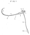
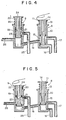
- Figs. 1 to 5 show an endoscope according to an embodiment of this invention, in which Fig. 1 is a general perspective view, Fig. 2 is a schematic view of a control section, and Figs. 3 to 5 are sectional views of an air-liquid suction device illustrative of different operating states.
- Now there will be described an embodiment of this invention with reference to the accompanying drawings. In Fig. 1,
numeral 1 denotes an endoscope which comprises acontrol section 2 capable of external operation, and anelongate insertion section 3 whose proximal end is connected with thecontrol section 2 to be inserted in the body of a patient. Theinsertion section 3 is composed of aflexible portion 4, abent portion 5, and a distal end portion 6 connected in succession from the side of thecontrol section 2. Thebent portion 5 may be bent to a desired degree by operating a control knob (not shown) attached to thecontrol section 2. Thecontrol section 2 is-connected with alight guide cable 30 having aconnector 30a at one end portion to be coupled to a light supply unit (not shown), and includes an eyepiece portion 7, an air-liquid selector valve 8, and asuction control valve 9. - The air-
liquid selector valve 8 and thesuction control valve 9 are constructed as shown in Figs. 2 to 5. The air-liquid selector valve 8 includes afirst cylinder 10 which, fixed to thecontrol section 2, is opened at the top and closed at the bottom. Afirst piston 11 with O-rings 12 thereon is fitted closely in thefirst cylinder 10 so as to be able to reciprocate therein, and is urged in a direction to project from thecylinder 10 by a first compression coil spring 13-which is disposed between the top flange of thepiston 11 and the top end face of thecylinder 10. Thefirst piston 11 has anair discharge hole 14 extending along the axial direction of thepiston 11 and opening at both top and bottom of thepiston 11, and a firstannular communication groove 15 formed in the outer peripheral surface of the end portion of thepiston 11 located inside thefirst cylinder 10. Formed in the peripheral wall of thefirst cylinder 10 are a feed-air port connected with one end of a feed-air tube 16, a feed-liquid port located above the feed-air port and connected with one end of a feed-liquid tube 17, and a port located between the feed-air and -liquid ports and connected with one end of aconnecting tube 18. In the air-liquid selector valve 8, as shown in Fig. 3, thepiston 11 is normally urged to its uppermost position by thefirst spring 13 to block up the feed-liquid tube 17, allowing the feed-air tube 16 to communicate with the open air by means of thecylinder 10 and theair discharge hole 14. - The
suction control valve 9 includes asecond cylinder 19 which is fixed to the.control section. 2 in parallel with thefirst cylinder 10 and is opened at the top and closed at the bottom. Asecond piston 20 with O-rings 21 thereon is fitted closely in the second cylinder -19 so as to be able to reciprocate therein, and is urged in a direction to project from thecylinder 19 by a secondcompression coil spring 22 which is disposed between the top flange of thepiston 20 and the top end face of thecylinder 19. Bored in thesecond piston 20 is anair inlet hole 24 which opens at one end on the top end face of thepiston 20 and at the other end into a secondannular communication groove 23 formed in the outer peripheral surface of the end portion of thepiston 20 located inside thecylinder 19. Formed in the peripheral wall of thesecond cylinder 19 are a port connected with the other end of theconnecting tube 18, a suction port located above the connectingtube 18 and connected with one end of asuction tube 25, and a port located between these two ports and connected with one end of acommon tube 26. In thesuction control valve 9, as shown in Fig. 3, thepiston 20 is normally urged to its uppermost position by thesecond spring 22 to allow thesuction tube 25 to communicate with the open air by means of thesecond communication groove 23. - The feed-
air tube 16, the feed-liquid tube 17, and thesuction tube 25 extend from thecontrol section 2 to pass through thelight guide cable 30 so that the other ends of these tubes are connected with feed-air, feed-liquid, and suction devices (not shown), respectively, by means of theconnector 30a. Thecommon tube 26 extends from thecontrol section 2 to open on the distal end face of theinsertion section 3. - Now there will be described the operation of the endoscope with the above-mentioned construction. First, when the feed-air, feed-liquid, and suction devices are operated with the air-liquid selector valve .8 and the
suction control valve 9 off, air fed into the feed-air tube 16 passes through thefirst cylinder 10 to be discharged from theair discharge hole 14 into the open air, while liquid fed into the feed-liquid tube 17 is prevented by thefirst piston 11 from flowing into thefirst cylinder 10. Further, a sucking force is produced inside thesuction tube 25, whereby the open air is sucked into thesuction tube 25 through theair inlet hole 24 and thesecond communication groove 23. - In air-feed`''operation, the
air discharge hole 14 of thefirst piston 11 is blocked up with an operator's finger, as shown in Fig. 3. Then, the air having so far been being discharged from theair discharge hole 14 into the open air comes to flow through the connectingtube 18 into thesecond cylinder 19, and passes therefrom through thecommon tube 26 to flow out into a body cavity from the distal end of theinsertion section 3 which is inserted in the body cavity. In liquid-feed operation, on the other hand, thefirst piston 11 is depressed against the restoring force of thefirst spring 13, as shown in Fig. 4. Then, the feed-liquid tube 17 is caused to communicate with the connectingtube 18 by means of thefirst communication groove 15, so that the liquid having so far been prevented from flowing by thefirst piston 11 is allowed to flow through thefirst communication groove 15 and the connectingtube 18 into thesecond cylinder 19, and passes therefrom through thecommon tube 26 to flow out into the body cavity. In sucking out mucus or the like from the body cavity, moreover, thesuction tube 25 is caused to communicate with thecommon tube 26 by means of thesecond communication groove 23 by depressing thesecond piston 20 against the restoring force of thesecond spring 22 while blocking up theair inlet hole 24 of thesecond piston 20 with the finger. Then, the sucking force of thesuction tube 25 having so far been sucking in the open air acts on the interior of the body cavity through thecommon tube 26, so that mucus or the like in the body cavity is sucked into thesuction tube 25 via thecommon tube 26 and thesecond communication groove 23. - In the endoscope with the above-mentioned construction, the air-liquid selector valve and the suction control valve are connected with a single common tube so that air feed, liquid feed, and suction may selectively be performed by means of the common tube. It is therefore possible to reduce the diameter of the insertion section through which the common tube extends.
- In the above-mentioned embodiment, the air-liquid selector valve and the suction control valve are connected by means of a connecting tube. Such a connecting tube, however, is unnecessary if these two valves are formed directly in contact or in one united body.
Claims (8)
Priority Applications (1)
| Application Number | Priority Date | Filing Date | Title |
|---|---|---|---|
| AT81109860T ATE8329T1 (en) | 1980-12-26 | 1981-11-24 | ENDOSCOPE WITH DEVICE FOR DELIVER OR. AIR AND LIQUID SUCTION. |
Applications Claiming Priority (2)
| Application Number | Priority Date | Filing Date | Title |
|---|---|---|---|
| JP55185941A JPS57110226A (en) | 1980-12-26 | 1980-12-26 | Air and liquid sending and sucking apparatus of endoscope |
| JP185941/80 | 1980-12-26 |
Publications (2)
| Publication Number | Publication Date |
|---|---|
| EP0055393A1 true EP0055393A1 (en) | 1982-07-07 |
| EP0055393B1 EP0055393B1 (en) | 1984-07-11 |
Family
ID=16179554
Family Applications (1)
| Application Number | Title | Priority Date | Filing Date |
|---|---|---|---|
| EP81109860A Expired EP0055393B1 (en) | 1980-12-26 | 1981-11-24 | An endoscope with an air-liquid suction device |
Country Status (5)
| Country | Link |
|---|---|
| US (1) | US4408598A (en) |
| EP (1) | EP0055393B1 (en) |
| JP (1) | JPS57110226A (en) |
| AT (1) | ATE8329T1 (en) |
| DE (1) | DE3164769D1 (en) |
Cited By (4)
| Publication number | Priority date | Publication date | Assignee | Title |
|---|---|---|---|---|
| FR2551342A1 (en) * | 1983-09-06 | 1985-03-08 | Warner Lambert Tech | SHUTTERING SYSTEM FOR MEDICAL AND VETERINARY OBSERVATION INSTRUMENTS |
| EP0199876A2 (en) * | 1985-04-19 | 1986-11-05 | Warner-Lambert Technologies, Inc. | Valve system for medical and veterinary appliances |
| EP0338557A2 (en) * | 1988-04-22 | 1989-10-25 | Opielab, Inc. | Contamination-free endoscope valves for use with a disposable endoscope sheath |
| US5419310A (en) * | 1992-11-03 | 1995-05-30 | Vision Sciences, Inc. | Partially inflated protective endoscope sheath |
Families Citing this family (31)
| Publication number | Priority date | Publication date | Assignee | Title |
|---|---|---|---|---|
| DE3309918C2 (en) * | 1982-03-29 | 1994-09-01 | Barry Oliver Weightman | Suction and flushing device |
| JPS6021735A (en) * | 1983-07-18 | 1985-02-04 | 旭光学工業株式会社 | Change-over device of endoscope |
| US5016614A (en) * | 1985-11-07 | 1991-05-21 | Macallister Niall P | Endotracheal intubation apparatus |
| JPS62133929A (en) * | 1985-12-06 | 1987-06-17 | オリンパス光学工業株式会社 | Endoscope |
| JP2590317B2 (en) * | 1986-05-21 | 1997-03-12 | オリンパス光学工業株式会社 | Endoscope |
| JP2917995B2 (en) * | 1988-05-25 | 1999-07-12 | 株式会社東芝 | Endoscope device |
| US4947896A (en) * | 1988-11-04 | 1990-08-14 | Bartlett Robert L | Laryngoscope |
| US5391145A (en) * | 1990-01-26 | 1995-02-21 | Dorsey, Iii; James H. | Irrigation control valve for endoscopic instrument |
| DE9003140U1 (en) * | 1990-03-17 | 1990-05-17 | Richard Wolf Gmbh, 7134 Knittlingen, De | |
| US5195958A (en) * | 1990-05-25 | 1993-03-23 | Phillips Edward H | Tool for laparoscopic surgery |
| US5333603A (en) * | 1992-02-25 | 1994-08-02 | Daniel Schuman | Endoscope with palm rest |
| US5254117A (en) * | 1992-03-17 | 1993-10-19 | Alton Dean Medical | Multi-functional endoscopic probe apparatus |
| TW259716B (en) * | 1992-10-09 | 1995-10-11 | Birtcher Med Syst | |
| US5645519A (en) * | 1994-03-18 | 1997-07-08 | Jai S. Lee | Endoscopic instrument for controlled introduction of tubular members in the body and methods therefor |
| US5697888A (en) * | 1994-04-21 | 1997-12-16 | Olympus Optical Co., Ltd. | Endoscope apparatus having valve device for supplying water and gas |
| DE19731965A1 (en) * | 1997-07-24 | 1999-01-28 | Etm Endotech Gmbh Medizintechn | Air / water and suction valves on endoscopes |
| US6354992B1 (en) * | 1999-11-08 | 2002-03-12 | Daniel T. Kato | Automated laparoscopic lens cleaner |
| US6800058B2 (en) | 2002-04-26 | 2004-10-05 | Medtronic, Inc. | System, method and apparatus for regulating vacuum supplied to surgical tools |
| US20040019358A1 (en) * | 2002-07-25 | 2004-01-29 | Scimed Life Systems, Inc. | Medical device |
| US8915842B2 (en) * | 2008-07-14 | 2014-12-23 | Ethicon Endo-Surgery, Inc. | Methods and devices for maintaining visibility and providing irrigation and/or suction during surgical procedures |
| US8206349B2 (en) | 2007-03-01 | 2012-06-26 | Medtronic Xomed, Inc. | Systems and methods for biofilm removal, including a biofilm removal endoscope for use therewith |
| US9326665B2 (en) | 2007-01-09 | 2016-05-03 | Medtronic Xomed, Inc. | Surgical instrument, system, and method for biofilm removal |
| US20080167527A1 (en) * | 2007-01-09 | 2008-07-10 | Slenker Dale E | Surgical systems and methods for biofilm removal, including a sheath for use therewith |
| US9827367B2 (en) | 2008-04-29 | 2017-11-28 | Medtronic Xomed, Inc. | Surgical instrument, system, and method for frontal sinus irrigation |
| WO2009157908A1 (en) | 2008-06-27 | 2009-12-30 | Davol, Inc. | Endoscopic vacuum controller |
| CN102131451B (en) * | 2009-03-30 | 2013-06-05 | 奥林巴斯医疗株式会社 | Fluid control device for endoscope |
| JP5570141B2 (en) * | 2009-05-20 | 2014-08-13 | Hoya株式会社 | Endoscope air / liquid suction device |
| JP5678238B2 (en) * | 2012-11-21 | 2015-02-25 | オリンパスメディカルシステムズ株式会社 | Endoscope flow path switching valve unit and endoscope |
| US9161680B2 (en) | 2013-11-26 | 2015-10-20 | Bracco Diagnostics Inc. | Disposable air/water valve for an endoscopic device |
| JP2022520881A (en) * | 2019-03-13 | 2022-04-01 | ティーヴィーエス モーター カンパニー リミテッド | Internal combustion engine |
| DE102021103087A1 (en) | 2021-02-10 | 2022-08-11 | Hendrik Seeburger | Suction valve and air/water valve for cavity instruments with a bridge element for flushing the suction channel |
Citations (2)
| Publication number | Priority date | Publication date | Assignee | Title |
|---|---|---|---|---|
| US3730645A (en) * | 1967-09-21 | 1973-05-01 | F Mashakaru | Air supplying device for an endoscope |
| US3903877A (en) * | 1973-06-13 | 1975-09-09 | Olympus Optical Co | Endoscope |
Family Cites Families (7)
| Publication number | Priority date | Publication date | Assignee | Title |
|---|---|---|---|---|
| JPS5216149Y2 (en) * | 1973-08-31 | 1977-04-12 | ||
| JPS5336632Y2 (en) * | 1973-11-22 | 1978-09-06 | ||
| JPS5915164B2 (en) * | 1976-09-17 | 1984-04-07 | 電気音響株式会社 | flyback transformer |
| US4261343A (en) * | 1978-03-28 | 1981-04-14 | Kabushiki Kaisha Medos Kenkyusho | Endoscope |
| US4270525A (en) * | 1978-04-17 | 1981-06-02 | Olympus Optical Co., Ltd. | Suction control device for an endoscope |
| US4193406A (en) * | 1978-09-18 | 1980-03-18 | Jinotti Walter J | Dual purpose catheter |
| JPS6220162Y2 (en) * | 1979-01-13 | 1987-05-22 |
-
1980
- 1980-12-26 JP JP55185941A patent/JPS57110226A/en active Granted
-
1981
- 1981-11-24 DE DE8181109860T patent/DE3164769D1/en not_active Expired
- 1981-11-24 EP EP81109860A patent/EP0055393B1/en not_active Expired
- 1981-11-24 US US06/324,655 patent/US4408598A/en not_active Expired - Lifetime
- 1981-11-24 AT AT81109860T patent/ATE8329T1/en not_active IP Right Cessation
Patent Citations (2)
| Publication number | Priority date | Publication date | Assignee | Title |
|---|---|---|---|---|
| US3730645A (en) * | 1967-09-21 | 1973-05-01 | F Mashakaru | Air supplying device for an endoscope |
| US3903877A (en) * | 1973-06-13 | 1975-09-09 | Olympus Optical Co | Endoscope |
Cited By (6)
| Publication number | Priority date | Publication date | Assignee | Title |
|---|---|---|---|---|
| FR2551342A1 (en) * | 1983-09-06 | 1985-03-08 | Warner Lambert Tech | SHUTTERING SYSTEM FOR MEDICAL AND VETERINARY OBSERVATION INSTRUMENTS |
| EP0199876A2 (en) * | 1985-04-19 | 1986-11-05 | Warner-Lambert Technologies, Inc. | Valve system for medical and veterinary appliances |
| EP0199876A3 (en) * | 1985-04-19 | 1987-05-20 | Warner-Lambert Technologies, Inc. | Valve system for medical and veterinary appliances |
| EP0338557A2 (en) * | 1988-04-22 | 1989-10-25 | Opielab, Inc. | Contamination-free endoscope valves for use with a disposable endoscope sheath |
| EP0338557A3 (en) * | 1988-04-22 | 1991-09-25 | Opielab, Inc. | Contamination-free endoscope valves for use with a disposable endoscope sheath |
| US5419310A (en) * | 1992-11-03 | 1995-05-30 | Vision Sciences, Inc. | Partially inflated protective endoscope sheath |
Also Published As
| Publication number | Publication date |
|---|---|
| US4408598A (en) | 1983-10-11 |
| EP0055393B1 (en) | 1984-07-11 |
| JPS57110226A (en) | 1982-07-09 |
| ATE8329T1 (en) | 1984-07-15 |
| JPH0157577B2 (en) | 1989-12-06 |
| DE3164769D1 (en) | 1984-08-16 |
Similar Documents
| Publication | Publication Date | Title |
|---|---|---|
| EP0055393B1 (en) | An endoscope with an air-liquid suction device | |
| EP0086989B1 (en) | Endoscope | |
| US10321813B2 (en) | Medical devices including distal chamber | |
| US4794913A (en) | Suction control unit for an endoscope | |
| US4641635A (en) | Endoscope apparatus | |
| US4598698A (en) | Diagnostic device | |
| US6595915B2 (en) | Jet nozzle for washing observation window of endoscopic insertion instrument | |
| US7341556B2 (en) | Endoscope with cleaning optics | |
| US7223231B2 (en) | Anti-twist casing for endoscopic manipulating head assembly | |
| EP2016914B1 (en) | Endoscope apparatus comprising an endoscope and an insertion assisting device | |
| EP2878252B1 (en) | Switching valve unit and endoscope apparatus | |
| US4270525A (en) | Suction control device for an endoscope | |
| EP1882443B1 (en) | Endscope system | |
| WO2004002334A1 (en) | Surgical instrument | |
| CN102186428A (en) | Surgical manipulator | |
| US5674183A (en) | Fiberscopes and spray modules | |
| GB2149884A (en) | Valve bodies for endoscopes | |
| US11832795B2 (en) | Fluid control device for endoscope, and endoscope | |
| GB2133696A (en) | Endoscope with built-in bulb | |
| JPS58200728A (en) | Air and water sending apparatus of endoscope | |
| JPH08266461A (en) | Pipeline changeover device for endoscope | |
| JPH0337601Y2 (en) | ||
| CN219021107U (en) | Suction valve, handle and endoscope | |
| JP4145579B2 (en) | Endoscopic air feeding / suction operation mechanism | |
| JP6655429B2 (en) | Medical equipment and medical system using the same |
Legal Events
| Date | Code | Title | Description |
|---|---|---|---|
| PUAI | Public reference made under article 153(3) epc to a published international application that has entered the european phase |
Free format text: ORIGINAL CODE: 0009012 |
|
| AK | Designated contracting states |
Designated state(s): AT BE CH DE FR GB IT NL SE |
|
| 17P | Request for examination filed |
Effective date: 19820601 |
|
| GRAA | (expected) grant |
Free format text: ORIGINAL CODE: 0009210 |
|
| AK | Designated contracting states |
Designated state(s): AT BE CH DE FR GB IT LI NL SE |
|
| PG25 | Lapsed in a contracting state [announced via postgrant information from national office to epo] |
Ref country code: IT Free format text: LAPSE BECAUSE OF FAILURE TO SUBMIT A TRANSLATION OF THE DESCRIPTION OR TO PAY THE FEE WITHIN THE PRESCRIBED TIME-LIMIT;WARNING: LAPSES OF ITALIAN PATENTS WITH EFFECTIVE DATE BEFORE 2007 MAY HAVE OCCURRED AT ANY TIME BEFORE 2007. THE CORRECT EFFECTIVE DATE MAY BE DIFFERENT FROM THE ONE RECORDED. Effective date: 19840711 Ref country code: SE Effective date: 19840711 Ref country code: NL Effective date: 19840711 Ref country code: LI Effective date: 19840711 Ref country code: BE Effective date: 19840711 Ref country code: AT Effective date: 19840711 Ref country code: CH Effective date: 19840711 |
|
| REF | Corresponds to: |
Ref document number: 8329 Country of ref document: AT Date of ref document: 19840715 Kind code of ref document: T |
|
| REF | Corresponds to: |
Ref document number: 3164769 Country of ref document: DE Date of ref document: 19840816 |
|
| REG | Reference to a national code |
Ref country code: CH Ref legal event code: PL |
|
| NLV1 | Nl: lapsed or annulled due to failure to fulfill the requirements of art. 29p and 29m of the patents act | ||
| PLBE | No opposition filed within time limit |
Free format text: ORIGINAL CODE: 0009261 |
|
| STAA | Information on the status of an ep patent application or granted ep patent |
Free format text: STATUS: NO OPPOSITION FILED WITHIN TIME LIMIT |
|
| 26N | No opposition filed | ||
| EN | Fr: translation not filed | ||
| GBPC | Gb: european patent ceased through non-payment of renewal fee | ||
| PG25 | Lapsed in a contracting state [announced via postgrant information from national office to epo] |
Ref country code: GB Effective date: 19881121 |
|
| PGFP | Annual fee paid to national office [announced via postgrant information from national office to epo] |
Ref country code: FR Payment date: 19891130 Year of fee payment: 9 |
|
| PGFP | Annual fee paid to national office [announced via postgrant information from national office to epo] |
Ref country code: DE Payment date: 19961202 Year of fee payment: 16 |
|
| PG25 | Lapsed in a contracting state [announced via postgrant information from national office to epo] |
Ref country code: DE Free format text: LAPSE BECAUSE OF NON-PAYMENT OF DUE FEES Effective date: 19980801 |
|
| PG25 | Lapsed in a contracting state [announced via postgrant information from national office to epo] |
Ref country code: FR Free format text: LAPSE BECAUSE OF FAILURE TO SUBMIT A TRANSLATION OF THE DESCRIPTION OR TO PAY THE FEE WITHIN THE PRESCRIBED TIME-LIMIT Effective date: 20001130 |
|
| PG25 | Lapsed in a contracting state [announced via postgrant information from national office to epo] |
Ref country code: FR Free format text: LAPSE BECAUSE OF FAILURE TO SUBMIT A TRANSLATION OF THE DESCRIPTION OR TO PAY THE FEE WITHIN THE PRESCRIBED TIME-LIMIT Effective date: 19901130 |