EP0057793A2 - Joint prosthesis, particularly an elbow prosthesis - Google Patents
Joint prosthesis, particularly an elbow prosthesis Download PDFInfo
- Publication number
- EP0057793A2 EP0057793A2 EP81305878A EP81305878A EP0057793A2 EP 0057793 A2 EP0057793 A2 EP 0057793A2 EP 81305878 A EP81305878 A EP 81305878A EP 81305878 A EP81305878 A EP 81305878A EP 0057793 A2 EP0057793 A2 EP 0057793A2
- Authority
- EP
- European Patent Office
- Prior art keywords
- component
- stem
- ulnar
- head
- articular
- Prior art date
- Legal status (The legal status is an assumption and is not a legal conclusion. Google has not performed a legal analysis and makes no representation as to the accuracy of the status listed.)
- Granted
Links
Images


Classifications
-
- A—HUMAN NECESSITIES
- A61—MEDICAL OR VETERINARY SCIENCE; HYGIENE
- A61F—FILTERS IMPLANTABLE INTO BLOOD VESSELS; PROSTHESES; DEVICES PROVIDING PATENCY TO, OR PREVENTING COLLAPSING OF, TUBULAR STRUCTURES OF THE BODY, e.g. STENTS; ORTHOPAEDIC, NURSING OR CONTRACEPTIVE DEVICES; FOMENTATION; TREATMENT OR PROTECTION OF EYES OR EARS; BANDAGES, DRESSINGS OR ABSORBENT PADS; FIRST-AID KITS
- A61F2/00—Filters implantable into blood vessels; Prostheses, i.e. artificial substitutes or replacements for parts of the body; Appliances for connecting them with the body; Devices providing patency to, or preventing collapsing of, tubular structures of the body, e.g. stents
- A61F2/02—Prostheses implantable into the body
- A61F2/30—Joints
- A61F2/38—Joints for elbows or knees
- A61F2/3804—Joints for elbows or knees for elbows
Definitions
- This invention relates to prostheses.
- United States Patent 3852831 describes an endoprosthetic elbow joint having an ulnar component with a saddle shaped bearing surface and a humeral component including a bifurcated member supporting a bearing member between the free ends of its arms.
- the humeral bearing member has a bearing surface which is arranged to engage in and across the saddle shaping of the ulnar component for mutual articulation.
- the ulnar component includes a platform with which a bearing member is releasably connected suitably by a sliding dovetail-section keying, the connecting interfaces are circularly curved, and the bearing member can pass through the humeral component.
- the angle between the forward direction of the tangent to the distal end of the articular surface of the ulnar component is at virtually 90° to the distal direction of a stem of the ulnar component, so that the prosthesis itself does not include anything to prevent the ulnar bearing member from dislocating posteriorly.
- United States Patent 4038704 discloses an elbow prosthesis comprising a humeral component and an ulnar component, in which each component comprises a joint portion for forming the joint of the prosthesis and an implant portion for implantation into the bone, the joint portion of the humeral component being capable of being received by the joint portion of theulnar component in snap-fit engagement, while permitting the humeral component to pivot relative to the ulnar component.
- the articular surface of the ulnar component subtends more than 180 at the axis of turning of the prosthesis.
- a serious disadvantage of such snap-fit is that, if the joint is dislocated, i.e.
- the articular surfaces of both components are of part-conical form. This has the disadvantage of requiring much greater precision in positioning of the components in the bones, because less tolerance in the joint is permissible.
- United States Patent 4057958 discloses an elbow prosthesis including humeral and ulnar components in which the head of the humeral component has a convex medial condylar formation presenting a smooth curved trochlear groove in the shape of part of a helix and providing a bearing surface for a head of the ulnar component and in which the ulnar component presents a condylar head contoured to fit into the trochlear groove, so that as the ulnar component turns around the humeral component, with the condylar head mating with the trochlear groove, the ulnar component moves along the pivotal axis and the ulnar performs the required valgus in extension and varus in flexion.
- the humeral articulation groove is in the shape of part of a helix, in order that the elbow adopts a valgus position in extension and a varus position in flexion.
- patients vary in that some have a valgus angle in extension of the elbow, some, but fewer, have a varus angle in extension, and others are between the two, namely having substantially zero angle in extension.
- This prosthesis in being designed for a valgus angle in extension cannot cope with the whole range, without serious risk of displacement.
- the risk of posterior dislocation is even -greater'than with the prosthesis of 3852831, in that the forward direction of the tangent to the distal end of the articular surface of the ulnar component is at less than a right angle to the distal direction of the stem of the ulnar component so that a force on the ulnar component in the proximal direction will actually tend to dislocate the ulnar component posteriorly relative to the humeral component.
- the head of the ulnar component is of a deep rectilinear three-dimensional form posteriorly, with the stem extending from the posterior surface, and therefore the component does not suit the natural internal shape of the olecranon fossa, with the result that a considerable amount of bone has to be removed and the joint thus undesirably weakened.
- United States Patent 3547115 describes an osteoarticular prosthesis and prosthetic method which is.particularly adapted for use on the distal humerus.
- the prosthesis has an outer articular surface corresponding to the articular surface being replaced.
- the bone upon which the prosthesis is to be mounted is preferably first trimmed to fit a keyhole-type opening in the prosthesis:
- the prosthesis has a sharpened leading edge and is transversely driven onto the bone. Once in place, the prosthesis is locked against displacement by its keyhole-type interengagement with the bone. Consequently, the articular surface of the prosthesis includes a part-spherical capitellum.
- the maximum radius of the capitellum relative to the axis of the joint is determined by the radius bone or radial component with which the capitellum co-operates. Since the articular surface of the humeral component co-operating with the ulna or ulnar component terminates at one axial end adjacent to this part-spherical capitellum, the radius of that one axial end is less than the maximum radius of the capitellum. Therefore, this one axial end presents a low obstruction to lateral displacement of the ulna or ulnar component relative to the humeral component in the direction of the capitellum.
- United States Patent 3,816,854 discloses a humeral component consisting of a generally cylindrical head of ultra high density polyethylene and a chrome- nickel-cobalt alloy stem incorporating at its distal end a hollow partial cylinder which closely embraces the head. Shallow protruberances on the inner surface of the partial cylinder engage in shallow depressions in the outer surface of the head to retain the head on the stem. Unfortunately, the reliability of the retention of the head in the partial cylinder is relatively low, depending as it does upon the protruberances and the depressions.
- United States Patent 4,131,956 describes a humeral component consisting of a generally cylindrical internally threaded head of a biocompatible plastics, a forked stem of biocompatible metal, and two screws screwed into the threaded interior of the head through the respective limbs of the fork of the stem.
- a forked stem has the disadvantage of requiring removal of a considerable amount of bone.
- the stem has at its proximal end a tenon poriton formed with a transverse bore.
- the head has at its proximal end a hinge part for receiving a hinge pin and at its distal end two prongs which embrace the tenon portion and are formed with respective bores which are countersunk at their outer ends and which can be brought into alignment with the bore in the tenon portion.
- a rivet inserted through the bores fastens the head to the stem. Flaring-out of the rivet is done by a surgeon applying a suitably designed G-clamp across the ends of the rivet.
- the fit of the tenon portion in the head is of an accuracy such as to provide a substantially rigid fit between the head and the stem.
- the reliability of the fastening depends upon the flaring-out of the rivet. If, because of incorrect positioning of the rivet, which is easily done, the G-clamp fails to flare-out the rivet sufficiently, then the rivet can work out laterally or medially, with serious results for the patient.
- an elbow replacement prosthesis comprising a humeral component having an articular surface that is curved convex in a sagittal plane, and an arcuate ulnar component having an articular surface that is curved concave in a sagittal plane and is complementary to said articular surface of said humeral component, said ulnar component having a stem extending therefrom opposite to said articular surface of said ulnar component and the articular surface of the ulnar component subtending at the axis of turning of the prosthesis an angle of less than 180 0,characterized in that the angle between the forward direction of the tangent to the distal end of said articular surface of said ulnar component and the distal direction of the longitudinal axis of said stem is more than 90°.
- the fact that the articular surfaces are complementary gives good stability to the joint. Because the articular surfaces are of curved convex and curved concave form a reasonable amount of tolerance in positioning of the components in the bones is allowable. Furthermore, because the articular surfaces are both symmetrical about a plane perpendicular to the axis of hinging of the prosthesis, the prosthesis can cope with all of the range of angle in extension of the elbow, from a valgus angle to a varus angle, which is particularly advantageous in arthritic patients.
- an elbow replacement prosthesis comprising an arcuate ulnar component having an articular bearing surface and, opposite said surface, an arcuate keel extending therealong with the arcuate curvature of said keel being similar.to that of said ulnar component, and a stem depending from said keel, characterized in that the dimension of said keel in p, coronal plane is substantially less than that of said bearing surface.
- Having the dimension of the keel in a coronal plane substantially less than that of the bearing surface has the advantage of minimizing the amount of bone needing to be removed. Since the articular surface of the olecranon process of the ulna naturally has an arcuate curvature, the making of the keel arcuate again minimises the amount of bone needing to be removed, although it is of course necessary to remove an arcuate segment of that surface in order to receive the arcuate keel. Minimizing of bone removal is also promoted by the fact that the radially outer surface of the arcuate articular portion of the ulnar component bears substantially face-to-face on the articular surface of the olecranon. Further minimising of bone removal can be achieved by ensuring that the dimension of that arcuate articular portion radially of the joint is as small as is practicable.
- a prosthetic component comprising an articular head, a first hole of closed cross-section extending in said head from a first surface zone of said head, a second hole extending in said head. from a second surface zone of said head and joining said first hole, a stem extending along said second hole and formed with an aperture therethrough aligned with said first hole, and a member extending in said first hole and said aperture and retaining said head on said stem, characterized in that said first hole is closed at its end remote from said first surface zone and is closed at said first surface zone by a plug therein.
- the elbow prosthesis can be useful in rehabilitating a patient with a severe arthritic problem of the elbow and may be easily inserted by any orthopaedic surgeon.
- the elbow replacement prosthesis 2 basically comprises a humeral component 4 that is implanted in the humerus 6 and an ulnar component 8 implanted in the ulna 10.
- a radial component 12 (Figure 17) that is implanted in the radius 14.
- the humeral component 4 has a surface 16 which is concave in the coronal plane and convex in the sagittal plane and which at its lateral end merges into a cylindrical surface 18, the latter partially replacing the capitulum bone of the humerus upon implantation. At its medial end the surface 16 merges into a convex surface 20.
- the surfaces 16, 18 and 20 form the articular surfaces of the humeral component 4 relative to the ulnar component and the radial component.
- humeral component 4A is used in the prosthesis for replacement of a totally destroyed elbow joint (see Figure 12).
- the component 4A is the same in all particulars to component 4 except that the articular surface 16A concave in the coronal plane extends right across the whole length of the component 4A. and there is no cylindrical surface such as surface 18 in component 4.
- the surface for attaching the humeral component 4 to the humerus comprises a superior U-slot 22 with chordal anterior wall 24, posterior wall 26 and flat floor 28.
- Longitudinal grooves 30 are formed in the walls 24 and 26 for keying of cement for implantation of the component 4.
- the lateral wall 32 has a peripheral groove 34 and the medial wall 36 a similar groove 38 for keying of cement.
- Annular wire markers 40 are imbedded in the walls 32 and 26 and a longitudinal wire marker 42 is embedded in the floor 28 so that position of the prosthesis can be determined by x-ray inspection, after implantation, of both the coronal and sagittal planes by means of the three markers.
- the main articulating surface of component 4 describes a gently concave curve in the coronal plane which allows for simple and effective engagement with the convex surface 44 in the coronal plane of the ulnar component 8.
- a limited amount of sideway rotation motion is allowed which may at times become necessary in order to avoid undue strain on the bony attachments to the prosthetic components.
- the convex articulating surface 16 increases in radius from its center in both the medial and lateral directions to a similar extent where the surfaces 18 and 20 take over.
- the articular surface 44 of ulnar component S allows for accurate and easy articulation with surface 16 of the humeral component 4.
- the bone attaching portion of the ulnar component 5 comprises a longitudinal, arcuate keel 46 with grooves 50 running longitudinally along beside the keel 48 for keying of cement in implantation.
- the keel 48 depends from the undersurface 54 of the arcuate articulating portion of the component S and has a dovetailed cross-section in the coronal plane.
- a stem 52 depends from the keel 48 for insertion into the ulna.
- the stem 52 has nipples 56 on both the medial surface 56 and lateral surface 60 for keying into cement for implantation.
- the orientation of the stem 52 relative to -the articular surface of the ulnar component is selected to control anteversion seating of the component 6 in the ulnar bone 10.
- the angle ⁇ between the forward direction F of the tangent T to the distal end 61 of the articular surface 44 of the ulnar component 8 and the distal direction D of the longitudin axis S of the stem 52 is more than 90°.
- the distal end 61 of the articular surface of the ulnar component is inclined forwardly generally in the direction F at an angle of more than 90° to the distal direction D of the stem 52.
- Making the capitellum surface 18 cylindrical has the advantage that the merging lateral end of the surface 16 provides a high obstruction to lateral displacements of the component 8 relative to the humeral component.
- a reconstructed elbow joint may also include a radial component 12 (Figure 17).
- the bone may be replaced with the radial component 12 which comprises a distal key portion 62 having cement keying grooves 64 and an integral proximal bearing button 66 with dished surface 68. If the component 12 is used, it is implanted into the surgically prepared radius 14 and fixed in place with cement in a manner similar to implant of the ulnar component 8.
- trial humeral components may be used, i.e., special component 70 or usual humeral component 72.
- the component 70 corresponds to the permanent special com--.ponent 4A and component 72 to the permanent usual component 4.
- the component 70 comprises the concave surface 74 in the coronal plane, lateral wall 76 and medial wall 76. Instead of a U-shaped slot as in the permanent component 4A, component 70 has an L-shaped slot defined by the posterior wall 50 and the floor 62.
- the component 72 comprises the concave surface 84 in the coronal plane, convex surfaces 86 & 88, medial wall 90, lateral wall 92 and an L-shaped slot defined by posterior wall 94 and floor 96.
- components 70 & 72 unlike their permanent counterparts 4 and 4A do not include wire markers or keying grooves, but, aside from this and the L-shaped slots, components 70 & 72 are the same as 4A & 4.
- the humeral component is formed of inert plastic, e.g. high density polyethylene, and the ulnar component 5 and radial component 12 are made of corrosion-resistant metal, e .g., the chromium alloy "Aluvium".
- the impactors and chisels are advantageously formed of stainless steel or equivalent metal except for the end of the ulnar impactor in contact with the ulnar prosthesis.
- the. humeral component should comprise a stem for insertion in the humerus.
- a suitable component is shown in Figures 1° and 20 which is of a left-hand style. It comprises an articular head 300 of inert plastics, with an. articular surface 301 similar in shape to the surface 16 and an articular surface 302 similar in shape to the surface 16.
- the head 300 is formed with respective co-axial undercut recesses 303 and 304, the undercut portions of which house wire markers 305. Extending co-axially from the recess 304 is a blind bore 306.
- the component comprises a metal stem 30° of which the distal end fits in the slot 307 and is formed with an aperture 310 aligned with the bore 306.
- a metal pin 311 retaining the stem 309 in the head 300.
- a plastics plug 312 closes the open end of the bore 306 and is a press-fit therein to prevent the pin 311 from sliding from or within the bore.
- the stem 309 is inserted into the slot 307, then the pin 311 is inserted through the aperture 310 and up to the blind end of the bore 306, and then the plug 312 is inserted into the open end of the bore 306 until it is firmly pressed against the pin 311 and is thus flush with the base of the recess 304.
- the humeral impactor 98 (or pusher) comprises a T-shaped handle 100 fixed in the coronal plane to the integral distal end member 102 having its pushing surface 104 formed complimentarily to the concave-convex surface 16 of component 4 or 300. This enables impactor 98 to be put in position upon the humeral component easily and be held there accurately while cement hardens during implantation.
- the ulnar impactor 106 also has a T-shaped handle 108, but this is fixed in the sagittal plane to the integral distal end member 110.
- the pushing surface 112 is formed complementarily to the articulating surface 44 of component 8 to again provide easy placement and accurate holding during cementing.
- Chisel 114 comprises mallet head 116, stem 118, base member 120 and two wings 122, each with chisel tips 124.
- the stem 11S is perpendicular to the base member 120. but offset from the center thereof for ease of access to the elbow joint.
- Chisel 114 is used to mark out the an t er o-posterior breadth of the huneral bone to be removed in order to fit into the slot 22 of component 4. It also marks the depth: equivalent to that of the depth of the slot 22 in component 4.
- Chisel 126 comprises mallet head 128, stem 130, base member 132, wings 134 with inset ends 136 and chisel tips 135.
- the wings 134 are in a different plane from the wings 122 of chisel 114.
- Chisel 126 is used for accurately marking out the length of humeral bone to be removed and also to mark the' depth since the inset ends 136 of the chisel are sized in length to compare with the depth of the body of component 4.
- Use of chisel 126 to mark out and cut away humeral bone from the humerus 6 is shown in Figure 13.
- Chisel 114 is then used in the opposite plane to mark out the antero-posterior breadth of bone removal.
- the humeral component 4 with cement applied to the surfaces of slot 22 is applied to the humerus 6 and held in place with impactor 98 as shown in Figure 14 until the cement has set.
- the keel of the prepared humeral bone sits in the U-slot of component 4 and its medial and lateral ends sit against the medial and lateral walls of the prepared lower humerus.
- the chisel 114 is not employed, but the chisel 126 is used in the same manner as with the component 4.
- the ulna is prepared to receive the stem 52 of ulnar component 8. Cement is then applied to the stem 52 and undersurface 54 and the component 8 is inserted into and onto the upper end of the ulna 10. The component 8 is held in position as shown in Figure 15 with impactor 108 until the cement is fully set. In the reconstructed joint, the ulnar component sits on the olecranon process of the ulnar bone and the stem 52 seats within that bone to give good stability to the component 8.
- a preferred cement for use in the new joint reconstructions is self-hardening methyl methacrylate cement, but other body compatible cements may be used.
- trial humeral components may be used in order to assess the depth of humeral bone to be removed and also for sizing of a component-to fit a particular patient.
- Figure 16 illustrates the application of the trial component 70 to the surgically prepared humeral bone 6.
- Figures 13-16 are illustrative only and do not attempt to depict the actual appearance of the operations. Obviously, the actual surgical procedures would be conducted under sterile conditions with the surgeon's hands gloved and there would be flesh around the humerus and ulna.
- the articulating surfaces e.g. 16 and 44, fit easily together and give a range of flexible movement between full extension (D°) to flexion position (140°). Stability is provided, in particular, by the intact medial ligament of the elbow and also by the lateral ligament, the anterior and posterior joint capsule and the adjacent musculature. Hence, any tendency for dislocation of the prosthesis is resisted by the natural anatomy and any lateral shift of the ulna is discouraged by the lateral cylindrical part 18 of 302 of the humeral component 4 or 300. This is useful if trauma or undue strain is delivered to the elbow joint. Further, the prosthetic articulating arrangement allows for rotation of the ulna at the elbow, thus avoiding strain on the seating of the two components in strain situations.
- Minimal bone is removed in the operative procedure which is a distinct advantage if there should be failure of the prosthesis for any reason, in which event, other surgical procedures can be easily accomplished.
- the humeral wire markers allow for accurate visualisation of the prosthesis by x-ray which is important in assessing wear and/or displacement after accidental trauma or loosening of the humeral component for any reason.
Abstract
Description
- This invention relates to prostheses.
- In general, prosthetic replacement of the elbow has proved a difficult and often disappointing task over the years and this has been the experience of most surgeons in this field. In the past, it was common to replace the elbow joint by means of a constrained prosthesis, usually consisting of a large stem inserted into the humerus and another into the ulna and the two parts of the component linked together by an axle pin. The strong forces on the elbow tend to disrupt the prosthesis from the bone and a very great deal of bone had to be removed to put in such a prosthesis, resulting in the long-term in a disastrous situation very often if the prosthesis has, in fact, to be removed.
- There has been a move in recent times to surface replacement of the elbow joint and my work in this area led to the development of a constrained device with a T-slot stability factor which is described in U.S. patent 4,079,469. Numerous other patents have issued describing bone joint prostheses of which the following is a representative listing:


- United States Patent 3852831 describes an endoprosthetic elbow joint having an ulnar component with a saddle shaped bearing surface and a humeral component including a bifurcated member supporting a bearing member between the free ends of its arms. The humeral bearing member has a bearing surface which is arranged to engage in and across the saddle shaping of the ulnar component for mutual articulation. In a preferred arrangement the ulnar component includes a platform with which a bearing member is releasably connected suitably by a sliding dovetail-section keying, the connecting interfaces are circularly curved, and the bearing member can pass through the humeral component. With this arrangement the humeral component and ulnar platform are fixed in place and the ulnar bearing member is then passed through the humeral component in bearing engagement therewith to connect with the platform. This prosthesis has the disadvantage of requiring removal of a considerable amount of bone, because the articular surface of the humeral component is of a fully circular form in a sagittal plane. Moreover, the articular surfaces are not complementary, and this has the disadvantage of giving an instability to the joint. Furthermore, the angle between the forward direction of the tangent to the distal end of the articular surface of the ulnar component is at virtually 90° to the distal direction of a stem of the ulnar component, so that the prosthesis itself does not include anything to prevent the ulnar bearing member from dislocating posteriorly.
- United States Patent 4038704 discloses an elbow prosthesis comprising a humeral component and an ulnar component, in which each component comprises a joint portion for forming the joint of the prosthesis and an implant portion for implantation into the bone, the joint portion of the humeral component being capable of being received by the joint portion of theulnar component in snap-fit engagement, while permitting the humeral component to pivot relative to the ulnar component. In order to achieve the snap-fit engagement between the humeral component and the ulnar component, the articular surface of the ulnar component subtends more than 180 at the axis of turning of the prosthesis. A serious disadvantage of such snap-fit is that, if the joint is dislocated, i.e. displaced to such extent that the components snap apart, they may well not snap back again, thus leaving the patient in a very dangerous condition. Moreover, the articular surfaces of both components are of part-conical form. This has the disadvantage of requiring much greater precision in positioning of the components in the bones, because less tolerance in the joint is permissible.
- United States Patent 4057958 discloses an elbow prosthesis including humeral and ulnar components in which the head of the humeral component has a convex medial condylar formation presenting a smooth curved trochlear groove in the shape of part of a helix and providing a bearing surface for a head of the ulnar component and in which the ulnar component presents a condylar head contoured to fit into the trochlear groove, so that as the ulnar component turns around the humeral component, with the condylar head mating with the trochlear groove, the ulnar component moves along the pivotal axis and the ulnar performs the required valgus in extension and varus in flexion. Thus, the humeral articulation groove is in the shape of part of a helix, in order that the elbow adopts a valgus position in extension and a varus position in flexion. However, patients vary in that some have a valgus angle in extension of the elbow, some, but fewer, have a varus angle in extension, and others are between the two, namely having substantially zero angle in extension. This prosthesis, in being designed for a valgus angle in extension cannot cope with the whole range, without serious risk of displacement. Furthermore, in this prosthesis, the risk of posterior dislocation is even -greater'than with the prosthesis of 3852831, in that the forward direction of the tangent to the distal end of the articular surface of the ulnar component is at less than a right angle to the distal direction of the stem of the ulnar component so that a force on the ulnar component in the proximal direction will actually tend to dislocate the ulnar component posteriorly relative to the humeral component. In addition the head of the ulnar component is of a deep rectilinear three-dimensional form posteriorly, with the stem extending from the posterior surface, and therefore the component does not suit the natural internal shape of the olecranon fossa, with the result that a considerable amount of bone has to be removed and the joint thus undesirably weakened.
- United States Patent 3547115 describes an osteoarticular prosthesis and prosthetic method which is.particularly adapted for use on the distal humerus. The prosthesis has an outer articular surface corresponding to the articular surface being replaced. The bone upon which the prosthesis is to be mounted is preferably first trimmed to fit a keyhole-type opening in the prosthesis: The prosthesis has a sharpened leading edge and is transversely driven onto the bone. Once in place, the prosthesis is locked against displacement by its keyhole-type interengagement with the bone. Consequently, the articular surface of the prosthesis includes a part-spherical capitellum. Naturally, the maximum radius of the capitellum relative to the axis of the joint is determined by the radius bone or radial component with which the capitellum co-operates. Since the articular surface of the humeral component co-operating with the ulna or ulnar component terminates at one axial end adjacent to this part-spherical capitellum, the radius of that one axial end is less than the maximum radius of the capitellum. Therefore, this one axial end presents a low obstruction to lateral displacement of the ulna or ulnar component relative to the humeral component in the direction of the capitellum.
- Similar comments apply in respect of United States Patent 3919725, which discloses an endoprosthetic elbow joint comprising humeral and ulnar components which are each of trough form. The humeral component outer surface is of circular cylindrical form over at least part of its length and is secured to the humerus at its inner surface, while the ulnar component has a complementary circular cylindrical inner surface for mutually articulatory bearing engagement with the humeral component and is secured to the ulna at its outer surface. In a modification the humeral component has a convex, part- annular, part-spherically shaped extension to its outer surface, which extension articulates with a complementary concave surface of an additional component for securement to the radius.
- Various ways are known of fixing a plastics prosthetic articular head to a metal prosthetic stem. For example, United States Patent 3,816,854 discloses a humeral component consisting of a generally cylindrical head of ultra high density polyethylene and a chrome- nickel-cobalt alloy stem incorporating at its distal end a hollow partial cylinder which closely embraces the head. Shallow protruberances on the inner surface of the partial cylinder engage in shallow depressions in the outer surface of the head to retain the head on the stem. Unfortunately, the reliability of the retention of the head in the partial cylinder is relatively low, depending as it does upon the protruberances and the depressions. United States Patent 4,131,956 describes a humeral component consisting of a generally cylindrical internally threaded head of a biocompatible plastics, a forked stem of biocompatible metal, and two screws screwed into the threaded interior of the head through the respective limbs of the fork of the stem. Such a forked stem has the disadvantage of requiring removal of a considerable amount of bone.
- In spite of the numerous procedures and devices previously developed and used for elbow reconstruction, there exists a need for further improvement particularly as regards resulting joint stability, minimal removal of bone for insertion and allowance for normal flexion and extension motion as well as minimal strain on the seating of the prosthesis.
- In order to facilitate implanting of an elbow prosthesis, it is known from United States Patent 3708805 to make the ulnar component in two separate parts, namely a stem and a head, fastenable together. The stem has at its proximal end a tenon poriton formed with a transverse bore. The head has at its proximal end a hinge part for receiving a hinge pin and at its distal end two prongs which embrace the tenon portion and are formed with respective bores which are countersunk at their outer ends and which can be brought into alignment with the bore in the tenon portion. A rivet inserted through the bores fastens the head to the stem. Flaring-out of the rivet is done by a surgeon applying a suitably designed G-clamp across the ends of the rivet. The fit of the tenon portion in the head is of an accuracy such as to provide a substantially rigid fit between the head and the stem.
- However, the reliability of the fastening depends upon the flaring-out of the rivet. If, because of incorrect positioning of the rivet, which is easily done, the G-clamp fails to flare-out the rivet sufficiently, then the rivet can work out laterally or medially, with serious results for the patient.
- According to one aspect of the present invention, there is provided an elbow replacement prosthesis comprising a humeral component having an articular surface that is curved convex in a sagittal plane, and an arcuate ulnar component having an articular surface that is curved concave in a sagittal plane and is complementary to said articular surface of said humeral component, said ulnar component having a stem extending therefrom opposite to said articular surface of said ulnar component and the articular surface of the ulnar component subtending at the axis of turning of the prosthesis an angle of less than 180 0,characterized in that the angle between the forward direction of the tangent to the distal end of said articular surface of said ulnar component and the distal direction of the longitudinal axis of said stem is more than 90°.
- Having the forward direction of the tangent to the distal end of the articular surface of the ulnar component at an angle of more than 90 degrees to the distal direction of the stem of the ulnar component, but without any snap-fit engagement between the components, has the advantage that forces in the proximal direction of that stem, which are common in normal use of the joint, do not tend to dislocate the ulnar component posteriorly relative to the humeral component. The risk of such dislocation is an important hazard in elbow replacement surgery and is greatly discouraged by this novel feature.
- Moreover, the fact that the articular surfaces are complementary gives good stability to the joint. Because the articular surfaces are of curved convex and curved concave form a reasonable amount of tolerance in positioning of the components in the bones is allowable. Furthermore, because the articular surfaces are both symmetrical about a plane perpendicular to the axis of hinging of the prosthesis, the prosthesis can cope with all of the range of angle in extension of the elbow, from a valgus angle to a varus angle, which is particularly advantageous in arthritic patients.
- According to a second aspect of the present invention, there is provide an elbow replacement prosthesis comprising an arcuate ulnar component having an articular bearing surface and, opposite said surface, an arcuate keel extending therealong with the arcuate curvature of said keel being similar.to that of said ulnar component, and a stem depending from said keel, characterized in that the dimension of said keel in p, coronal plane is substantially less than that of said bearing surface.
- Having the dimension of the keel in a coronal plane substantially less than that of the bearing surface has the advantage of minimizing the amount of bone needing to be removed. Since the articular surface of the olecranon process of the ulna naturally has an arcuate curvature, the making of the keel arcuate again minimises the amount of bone needing to be removed, although it is of course necessary to remove an arcuate segment of that surface in order to receive the arcuate keel. Minimizing of bone removal is also promoted by the fact that the radially outer surface of the arcuate articular portion of the ulnar component bears substantially face-to-face on the articular surface of the olecranon. Further minimising of bone removal can be achieved by ensuring that the dimension of that arcuate articular portion radially of the joint is as small as is practicable.
- According to a third aspect of the present invention, there is provided a prosthetic component comprising an articular head, a first hole of closed cross-section extending in said head from a first surface zone of said head, a second hole extending in said head. from a second surface zone of said head and joining said first hole, a stem extending along said second hole and formed with an aperture therethrough aligned with said first hole, and a member extending in said first hole and said aperture and retaining said head on said stem, characterized in that said first hole is closed at its end remote from said first surface zone and is closed at said first surface zone by a plug therein.
- Thereby, not only can the head be reliably retained.-on the stem, but the amount of bone needing to be removed can be minimal.
- Owing to the present invention, it is possible to obtain an elbow prosthesis having the following advantages:
- (i) Minimal removal of bone for insertion.
- (ii) Protection of the ulnar nerve within the cubital tunnel by preservation of the medial lip of the trochlea.
- (iii) Allowance for normal flexion and extension motion at the elbow.
- (iv) Stability, which is importantly achieved by the arrangement of the joint articulation that guards against undue medial and lateral movement which would be abnormal for the elbow.
- (v) Additional overall stability that ensues from minimal interference with ligaments and capsule associated with the operative technique.
- (vi) Lightness in weight.
- (vii) Relatively inexpensive to produce.
- (viii) Should removal of the implant be necessary, e.g., for infection, the patient would be left with a conventional excision arthroplasty which should give useful function.
- Moreover, the elbow prosthesis can be useful in rehabilitating a patient with a severe arthritic problem of the elbow and may be easily inserted by any orthopaedic surgeon.
- In order that the invention may be clearly understood and readily carried into effect, reference will now be made by way of example to the accompanying drawings, in which:-
- Figure 1 is a fragmentary anterior elevation of an elbow prosthesis illustrated as implanted in the humerus and ulna.
- Figure 2 is a fragmentary lateral elevation of the elbow prosthesis with humerus and ulna in extension postion (00).
- Figure 3 is a perspective view of an ulnar component of the prosthesis.
- Figure 4 is a perspective view of a humeral component of the prosthesis.
- Figure 5 is a perspective view of a humeral component impactor.
- Figure 6 is a perspective view of an ulnar component impactor.
- Figure 7 is a perspective view of a chisel used to cut the humerus for implanting the humeral component.
- Figure 8 is a perspective view of one embodiment of a trial humeral component used primarily for replacement of a totally destroyed elbow joint.
- Figure 9 is a perspective view of another embodiment of a trial humeral component.
- Figure 10 is a perspective view of another chisel used in implanting the humeral component.
- Figure 11 is a plan view of the usual form of humeral component of the new prosthesis.
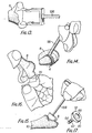
- Figure 12 is a plan view of the special form of humeral component used for replacement of a totally destroyed elbow joint.
- Figure 13 is a fragmentary perspective view of a chisel cutting the humerus for implantation of the humeral component.
- Figure 14 is a fragmentary perspective view of a humeral impactor pushing the humeral component onto the humeral bone during cementing.
- Figure 15 is a fragmentary perspective view of an ulnar impactor pushing the ulnar component onto the ulnar bone during cementing.
- Figure 16 is a fragmentary perspective view of a trial humeral component being applied to the humerus.
- Figure 17 is a perspective view of a radial head component that may be used on occasion in the new elbow replacement prosthesis.
- Figure 18 is a sectional view taken on the line A-A of Figure 1.
- Figure 19 is an elevation in thelateral direction of a modified version of the humeral component.
- Figure 20 is an elevation in the distal direction of the modified version.
- Referring in detail to the drawings, the
elbow replacement prosthesis 2 basically comprises a humeral component 4 that is implanted in thehumerus 6 and anulnar component 8 implanted in theulna 10. Optionally, it may comprise a radial component 12 (Figure 17) that is implanted in theradius 14. - The humeral component 4 has a
surface 16 which is concave in the coronal plane and convex in the sagittal plane and which at its lateral end merges into acylindrical surface 18, the latter partially replacing the capitulum bone of the humerus upon implantation. At its medial end thesurface 16 merges into aconvex surface 20. Thesurfaces - A slightly different form of
humeral component 4A is used in the prosthesis for replacement of a totally destroyed elbow joint (see Figure 12). Thecomponent 4A is the same in all particulars to component 4 except that thearticular surface 16A concave in the coronal plane extends right across the whole length of the component 4A. and there is no cylindrical surface such assurface 18 in component 4. - The surface for attaching the humeral component 4 to the humerus comprises a superior U-slot 22 with chordal
anterior wall 24,posterior wall 26 andflat floor 28.Longitudinal grooves 30 are formed in thewalls lateral wall 32 has aperipheral groove 34 and the medial wall 36 asimilar groove 38 for keying of cement. Annular wire markers 40are imbedded in thewalls longitudinal wire marker 42 is embedded in thefloor 28 so that position of the prosthesis can be determined by x-ray inspection, after implantation, of both the coronal and sagittal planes by means of the three markers. - The main articulating surface of component 4 describes a gently concave curve in the coronal plane which allows for simple and effective engagement with the
convex surface 44 in the coronal plane of theulnar component 8. Thus, a limited amount of sideway rotation motion is allowed which may at times become necessary in order to avoid undue strain on the bony attachments to the prosthetic components. - In the sagittal plane of the component 4, the convex articulating
surface 16 increases in radius from its center in both the medial and lateral directions to a similar extent where thesurfaces - The
articular surface 44 of ulnar component S allows for accurate and easy articulation withsurface 16 of the humeral component 4. - The bone attaching portion of the ulnar component 5 comprises a longitudinal, arcuate keel 46 with
grooves 50 running longitudinally along beside thekeel 48 for keying of cement in implantation. Thekeel 48 depends from theundersurface 54 of the arcuate articulating portion of the component S and has a dovetailed cross-section in the coronal plane. Astem 52 depends from thekeel 48 for insertion into the ulna. Thestem 52 hasnipples 56 on both themedial surface 56 andlateral surface 60 for keying into cement for implantation. - The orientation of the
stem 52 relative to -the articular surface of the ulnar component is selected to control anteversion seating of thecomponent 6 in theulnar bone 10. With reference to Figure 18, the angle α between the forward direction F of the tangent T to thedistal end 61 of thearticular surface 44 of theulnar component 8 and the distal direction D of the longitudin axis S of thestem 52 is more than 90°. Hence thedistal end 61 of the articular surface of the ulnar component is inclined forwardly generally in the direction F at an angle of more than 90° to the distal direction D of thestem 52. The advantage of this feature is that forces in the direction 150° to the direction D, which are common in normal use of the joint, do not tend to dislocate the ulnar component posteriorly relative to the humeral component. The risk of such dislocation is an important hazard in elbow replacement surgery and is greatly mitigated by this feature of the new prosthesis. Figure 18 also shows that the articular surface of the ulnar component B subtends at the axis J of the turning of the joint an angle of less than 180°. The advantage of this feature is that if the joint should become dislocated the two components will not be prevented from returning to a proper position with their respective articular surfaces in contact with one another. Cement between each component and theulna 10 or thehumerus 6 is indicated in Figure 18 by thesolid shading 200. - Making the
capitellum surface 18 cylindrical has the advantage that the merging lateral end of thesurface 16 provides a high obstruction to lateral displacements of thecomponent 8 relative to the humeral component. - A reconstructed elbow joint may also include a radial component 12 (Figure 17). In actual fact, although the head of the
radius 14 is always removed for insertion of the prosthesis, it is not always necessary to replace this removed bone. However, in necessary cases, the bone may be replaced with theradial component 12 which comprises a distalkey portion 62 havingcement keying grooves 64 and an integralproximal bearing button 66 with dishedsurface 68. If thecomponent 12 is used, it is implanted into the surgicallyprepared radius 14 and fixed in place with cement in a manner similar to implant of theulnar component 8. - In order to assess the depth of humeral bone to be removed and also for sizing of a component to fit a particular patient, trial humeral components may be used, i.e.,
special component 70 or usualhumeral component 72. Thecomponent 70 corresponds to the permanent special com--.ponent 4A andcomponent 72 to the permanent usual component 4. - The
component 70 comprises theconcave surface 74 in the coronal plane,lateral wall 76 andmedial wall 76. Instead of a U-shaped slot as in thepermanent component 4A,component 70 has an L-shaped slot defined by theposterior wall 50 and thefloor 62. - The
component 72 comprises theconcave surface 84 in the coronal plane,convex surfaces 86 & 88,medial wall 90,lateral wall 92 and an L-shaped slot defined byposterior wall 94 andfloor 96. - The
components 70 & 72, unlike theirpermanent counterparts 4 and 4A do not include wire markers or keying grooves, but, aside from this and the L-shaped slots,components 70 & 72 are the same as 4A & 4. - In reconstruction of an elbow joint, only one style of
components component 72, right and left hand styles must be used dependent upon whether a right or left elbow is being reconstructed. - A variety of materials are available from which to construct
components radial component 12 are made of corrosion-resistant metal, e.g., the chromium alloy "Aluvium". The impactors and chisels are advantageously formed of stainless steel or equivalent metal except for the end of the ulnar impactor in contact with the ulnar prosthesis. - The design of the
components 4 and 8 as -described enables them to be made and used in an average size adaptable to a large number of patients. However, it should be recognised that different sizes may be necessary and this can be determined by use ofsized trial components - In some cases, it may be desired that the. humeral component should comprise a stem for insertion in the humerus. A suitable component is shown in Figures 1° and 20 which is of a left-hand style. It comprises an
articular head 300 of inert plastics, with an.articular surface 301 similar in shape to thesurface 16 and anarticular surface 302 similar in shape to thesurface 16. In its medial and lateral ends, thehead 300 is formed with respective co-axial undercutrecesses house wire markers 305. Extending co-axially from therecess 304 is ablind bore 306. This intersects aradial slot 307 which itself intersects achannel 308 forming a discontinuity in thearticular surfaces metal stem 30° of which the distal end fits in theslot 307 and is formed with anaperture 310 aligned with thebore 306. Through theaperture 310 and projecting beyond both ends thereof is ametal pin 311 retaining thestem 309 in thehead 300. A plastics plug 312 closes the open end of thebore 306 and is a press-fit therein to prevent thepin 311 from sliding from or within the bore. In assembling the component, thestem 309 is inserted into theslot 307, then thepin 311 is inserted through theaperture 310 and up to the blind end of thebore 306, and then theplug 312 is inserted into the open end of thebore 306 until it is firmly pressed against thepin 311 and is thus flush with the base of therecess 304. - Instrumentation for reconstruction of an elbow joint is shown in Figures 5-7 and 10.
- The humeral impactor 98 (or pusher) comprises a T-shaped
handle 100 fixed in the coronal plane to the integraldistal end member 102 having its pushingsurface 104 formed complimentarily to the concave-convex surface 16 ofcomponent 4 or 300. This enables impactor 98 to be put in position upon the humeral component easily and be held there accurately while cement hardens during implantation. - The
ulnar impactor 106 also has a T-shapedhandle 108, but this is fixed in the sagittal plane to the integraldistal end member 110. The pushingsurface 112 is formed complementarily to the articulatingsurface 44 ofcomponent 8 to again provide easy placement and accurate holding during cementing. -
Chisel 114 comprisesmallet head 116,stem 118,base member 120 and twowings 122, each withchisel tips 124. The stem 11S is perpendicular to thebase member 120. but offset from the center thereof for ease of access to the elbow joint.Chisel 114 is used to mark out the antero-posterior breadth of the huneral bone to be removed in order to fit into theslot 22 of component 4. It also marks the depth: equivalent to that of the depth of theslot 22 in component 4. -
Chisel 126 comprisesmallet head 128,stem 130,base member 132,wings 134 with inset ends 136 and chisel tips 135. Thewings 134 are in a different plane from thewings 122 ofchisel 114. -
Chisel 126 is used for accurately marking out the length of humeral bone to be removed and also to mark the' depth since the inset ends 136 of the chisel are sized in length to compare with the depth of the body of component 4. Use ofchisel 126 to mark out and cut away humeral bone from thehumerus 6 is shown in Figure 13.Chisel 114 is then used in the opposite plane to mark out the antero-posterior breadth of bone removal. Upon completion of humeral bone removal in such manner, the humeral component 4, with cement applied to the surfaces ofslot 22 is applied to thehumerus 6 and held in place withimpactor 98 as shown in Figure 14 until the cement has set. The keel of the prepared humeral bone sits in the U-slot of component 4 and its medial and lateral ends sit against the medial and lateral walls of the prepared lower humerus. - In implantation of the
humeral component 300, thechisel 114 is not employed, but thechisel 126 is used in the same manner as with the component 4. - The ulna is prepared to receive the
stem 52 ofulnar component 8. Cement is then applied to thestem 52 andundersurface 54 and thecomponent 8 is inserted into and onto the upper end of theulna 10. Thecomponent 8 is held in position as shown in Figure 15 withimpactor 108 until the cement is fully set. In the reconstructed joint, the ulnar component sits on the olecranon process of the ulnar bone and thestem 52 seats within that bone to give good stability to thecomponent 8. - A preferred cement for use in the new joint reconstructions is self-hardening methyl methacrylate cement, but other body compatible cements may be used.
- As previously indicated, trial humeral components may be used in order to assess the depth of humeral bone to be removed and also for sizing of a component-to fit a particular patient. Figure 16 illustrates the application of the
trial component 70 to the surgically preparedhumeral bone 6. - It is to be understood that Figures 13-16 are illustrative only and do not attempt to depict the actual appearance of the operations. Obviously, the actual surgical procedures would be conducted under sterile conditions with the surgeon's hands gloved and there would be flesh around the humerus and ulna.
- In the reconstructed elbow joint, the articulating surfaces, e.g. 16 and 44, fit easily together and give a range of flexible movement between full extension (D°) to flexion position (140°). Stability is provided, in particular, by the intact medial ligament of the elbow and also by the lateral ligament, the anterior and posterior joint capsule and the adjacent musculature. Hence, any tendency for dislocation of the prosthesis is resisted by the natural anatomy and any lateral shift of the ulna is discouraged by the lateral
cylindrical part 18 of 302 of thehumeral component 4 or 300. This is useful if trauma or undue strain is delivered to the elbow joint. Further, the prosthetic articulating arrangement allows for rotation of the ulna at the elbow, thus avoiding strain on the seating of the two components in strain situations. - Minimal bone is removed in the operative procedure which is a distinct advantage if there should be failure of the prosthesis for any reason, in which event, other surgical procedures can be easily accomplished.
- The humeral wire markers allow for accurate visualisation of the prosthesis by x-ray which is important in assessing wear and/or displacement after accidental trauma or loosening of the humeral component for any reason.
Claims (5)
Applications Claiming Priority (2)
| Application Number | Priority Date | Filing Date | Title |
|---|---|---|---|
| GB8039835 | 1980-12-12 | ||
| GB8039835 | 1980-12-12 |
Publications (3)
| Publication Number | Publication Date |
|---|---|
| EP0057793A2 true EP0057793A2 (en) | 1982-08-18 |
| EP0057793A3 EP0057793A3 (en) | 1982-09-08 |
| EP0057793B1 EP0057793B1 (en) | 1986-04-23 |
Family
ID=10517935
Family Applications (1)
| Application Number | Title | Priority Date | Filing Date |
|---|---|---|---|
| EP81305878A Expired EP0057793B1 (en) | 1980-12-12 | 1981-12-14 | Joint prosthesis, particularly an elbow prosthesis |
Country Status (2)
| Country | Link |
|---|---|
| EP (1) | EP0057793B1 (en) |
| DE (1) | DE3174491D1 (en) |
Citations (8)
| Publication number | Priority date | Publication date | Assignee | Title |
|---|---|---|---|---|
| US3708805A (en) * | 1969-12-24 | 1973-01-09 | Nat Res Dev | Prosthetic elbow joint |
| US3852831A (en) * | 1973-01-31 | 1974-12-10 | Nat Res Dev | Endoprosthetic elbow joint |
| US3919725A (en) * | 1972-11-30 | 1975-11-18 | Nat Res Dev | Endoprosthetic elbow joint devices |
| DE2529238A1 (en) * | 1974-07-03 | 1976-01-29 | Nat Research Dev Corp London | ENDOPROSTHETIC ELBOW JOINT |
| US4057858A (en) * | 1975-02-17 | 1977-11-15 | Arthur Jacob Helfet | Elbow prosthesis |
| US4079469A (en) * | 1975-12-12 | 1978-03-21 | Thomas Gordon Wadsworth | Elbow joint endoprosthesis |
| GB1528906A (en) * | 1974-10-11 | 1978-10-18 | Nat Res Dev | Endoprosthetic devices |
| EP0006314A1 (en) * | 1978-05-31 | 1980-01-09 | Thomas Gordon Wadsworth | Elbow prosthesis and instrumentation for implantation of the prosthesis |
-
1981
- 1981-12-14 EP EP81305878A patent/EP0057793B1/en not_active Expired
- 1981-12-14 DE DE8181305878T patent/DE3174491D1/en not_active Expired
Patent Citations (8)
| Publication number | Priority date | Publication date | Assignee | Title |
|---|---|---|---|---|
| US3708805A (en) * | 1969-12-24 | 1973-01-09 | Nat Res Dev | Prosthetic elbow joint |
| US3919725A (en) * | 1972-11-30 | 1975-11-18 | Nat Res Dev | Endoprosthetic elbow joint devices |
| US3852831A (en) * | 1973-01-31 | 1974-12-10 | Nat Res Dev | Endoprosthetic elbow joint |
| DE2529238A1 (en) * | 1974-07-03 | 1976-01-29 | Nat Research Dev Corp London | ENDOPROSTHETIC ELBOW JOINT |
| GB1528906A (en) * | 1974-10-11 | 1978-10-18 | Nat Res Dev | Endoprosthetic devices |
| US4057858A (en) * | 1975-02-17 | 1977-11-15 | Arthur Jacob Helfet | Elbow prosthesis |
| US4079469A (en) * | 1975-12-12 | 1978-03-21 | Thomas Gordon Wadsworth | Elbow joint endoprosthesis |
| EP0006314A1 (en) * | 1978-05-31 | 1980-01-09 | Thomas Gordon Wadsworth | Elbow prosthesis and instrumentation for implantation of the prosthesis |
Also Published As
| Publication number | Publication date |
|---|---|
| EP0057793A3 (en) | 1982-09-08 |
| EP0057793B1 (en) | 1986-04-23 |
| DE3174491D1 (en) | 1986-05-28 |
Similar Documents
| Publication | Publication Date | Title |
|---|---|---|
| US4378607A (en) | Elbow replacement prosthesis | |
| EP1480582B1 (en) | Patello-femoral joint replacement | |
| AU605016B2 (en) | Prosthetic knee joint with improved patellar component tracking | |
| US6800094B2 (en) | Mobile bearing patellar prosthesis with orbital translation | |
| US4686978A (en) | Instrumentation for implantation of an elbow prosthesis | |
| US6916341B2 (en) | Device and method for bicompartmental arthroplasty | |
| EP0349173A1 (en) | Knee prosthesis | |
| US20050154470A1 (en) | Modular phrosthesis assembly including tapered adjustments | |
| GB2046100A (en) | Tibial prosthesis | |
| US20090132055A1 (en) | Arthroplasty device | |
| EP3355834B1 (en) | Tibial prosthesis for tibia with varus resection | |
| US20210307914A1 (en) | Orthopaedic prosthetic system for a rotating hinged-knee prosthesis | |
| CN110638508A (en) | Customized patient-specific orthopaedic surgical instrument | |
| EP3049027B1 (en) | Reverse knee prosthesis | |
| EP0006314A1 (en) | Elbow prosthesis and instrumentation for implantation of the prosthesis | |
| EP1631221B1 (en) | Surgical device | |
| EP0057793A2 (en) | Joint prosthesis, particularly an elbow prosthesis | |
| GB2094638A (en) | Elbow replacement prosthesis instrumentation | |
| EP3692951A1 (en) | Orthopaedic prosthetic system for a rotating hinged-knee prosthesis | |
| GB2094639A (en) | Elbow replacement prosthesis | |
| WO2004000175A1 (en) | Unicompartmental prosthetic knee joint device | |
| CA1333143C (en) | Femoral drill jig | |
| US20170216040A1 (en) | Total knee femoral component with flexible anterior flange | |
| GB2422110A (en) | Ligament saving knee prosthesis |
Legal Events
| Date | Code | Title | Description |
|---|---|---|---|
| PUAI | Public reference made under article 153(3) epc to a published international application that has entered the european phase |
Free format text: ORIGINAL CODE: 0009012 |
|
| PUAL | Search report despatched |
Free format text: ORIGINAL CODE: 0009013 |
|
| AK | Designated contracting states |
Designated state(s): CH DE FR GB |
|
| AK | Designated contracting states |
Designated state(s): CH DE FR GB |
|
| 17P | Request for examination filed |
Effective date: 19830223 |
|
| GRAA | (expected) grant |
Free format text: ORIGINAL CODE: 0009210 |
|
| AK | Designated contracting states |
Kind code of ref document: B1 Designated state(s): CH DE FR GB LI |
|
| REF | Corresponds to: |
Ref document number: 3174491 Country of ref document: DE Date of ref document: 19860528 |
|
| ET | Fr: translation filed | ||
| PLBE | No opposition filed within time limit |
Free format text: ORIGINAL CODE: 0009261 |
|
| STAA | Information on the status of an ep patent application or granted ep patent |
Free format text: STATUS: NO OPPOSITION FILED WITHIN TIME LIMIT |
|
| 26N | No opposition filed | ||
| PGFP | Annual fee paid to national office [announced via postgrant information from national office to epo] |
Ref country code: GB Payment date: 19951122 Year of fee payment: 15 |
|
| PGFP | Annual fee paid to national office [announced via postgrant information from national office to epo] |
Ref country code: CH Payment date: 19951222 Year of fee payment: 15 |
|
| PGFP | Annual fee paid to national office [announced via postgrant information from national office to epo] |
Ref country code: FR Payment date: 19951228 Year of fee payment: 15 |
|
| PGFP | Annual fee paid to national office [announced via postgrant information from national office to epo] |
Ref country code: DE Payment date: 19960206 Year of fee payment: 15 |
|
| PG25 | Lapsed in a contracting state [announced via postgrant information from national office to epo] |
Ref country code: GB Effective date: 19961214 |
|
| PG25 | Lapsed in a contracting state [announced via postgrant information from national office to epo] |
Ref country code: LI Effective date: 19961231 Ref country code: CH Effective date: 19961231 |
|
| GBPC | Gb: european patent ceased through non-payment of renewal fee |
Effective date: 19961214 |
|
| REG | Reference to a national code |
Ref country code: CH Ref legal event code: PL |
|
| PG25 | Lapsed in a contracting state [announced via postgrant information from national office to epo] |
Ref country code: FR Effective date: 19970829 |
|
| PG25 | Lapsed in a contracting state [announced via postgrant information from national office to epo] |
Ref country code: DE Effective date: 19970902 |
|
| REG | Reference to a national code |
Ref country code: FR Ref legal event code: ST |