EP0058056A2 - Apparatus for and method of continual remote monitoring of a local condition of a liquid in a machine part - Google Patents
Apparatus for and method of continual remote monitoring of a local condition of a liquid in a machine part Download PDFInfo
- Publication number
- EP0058056A2 EP0058056A2 EP82300566A EP82300566A EP0058056A2 EP 0058056 A2 EP0058056 A2 EP 0058056A2 EP 82300566 A EP82300566 A EP 82300566A EP 82300566 A EP82300566 A EP 82300566A EP 0058056 A2 EP0058056 A2 EP 0058056A2
- Authority
- EP
- European Patent Office
- Prior art keywords
- liquid
- container
- plate
- light
- contained
- Prior art date
- Legal status (The legal status is an assumption and is not a legal conclusion. Google has not performed a legal analysis and makes no representation as to the accuracy of the status listed.)
- Withdrawn
Links
Images


Classifications
-
- G—PHYSICS
- G01—MEASURING; TESTING
- G01F—MEASURING VOLUME, VOLUME FLOW, MASS FLOW OR LIQUID LEVEL; METERING BY VOLUME
- G01F23/00—Indicating or measuring liquid level or level of fluent solid material, e.g. indicating in terms of volume or indicating by means of an alarm
- G01F23/30—Indicating or measuring liquid level or level of fluent solid material, e.g. indicating in terms of volume or indicating by means of an alarm by floats
- G01F23/32—Indicating or measuring liquid level or level of fluent solid material, e.g. indicating in terms of volume or indicating by means of an alarm by floats using rotatable arms or other pivotable transmission elements
- G01F23/36—Indicating or measuring liquid level or level of fluent solid material, e.g. indicating in terms of volume or indicating by means of an alarm by floats using rotatable arms or other pivotable transmission elements using electrically actuated indicating means
- G01F23/366—Indicating or measuring liquid level or level of fluent solid material, e.g. indicating in terms of volume or indicating by means of an alarm by floats using rotatable arms or other pivotable transmission elements using electrically actuated indicating means using optoelectrically actuated indicating means
Definitions
- This invention relates to apparatus for and a method of continual remote monttoring of a local condition, such as the temperature, the pressure, or the volume, of a liquid in a machine in operation and which includes one or more parts wherein liquid is contained and fulfils a function the success of which is contingent upon a variable quantity in a range departure from which is susceptible of interfering with, or at least impairing to a greater or lesser degree, the operation of the machine.
- a local condition such as the temperature, the pressure, or the volume
- the invention is applicable, for example, to the continual monitoring of the oil level in the tank of mining machinery in operation.
- An object of the present invention is to obviate or mitigate these disadvantages.
- a method of continual remote monitoring of a local condition of a liquid as aforesaid comprises transmitting light by means of optical fibres from a source to light-responsive indicating means along a trajectory passing through the liquid container, and mounting in the container an . opaque plate the position or attitude of which changes as the quantity to be monitored of the liquid varies such that a warning indication is given when said liquid-quantity departs from said range.
- the light is split into a plurality of beams passing through the container such that the plate affects each beam in succession as said liquid quantity varies.
- apparatus for continual remote monotoring of a.local condition of a liquid comprises a light source, a light-responsive indicating means including a warning indicator, optical fibres transmitting light from the source to the indicating means along a trajectory passing through the liquid container,and an opaque plate mounted in the container in such manner that its position or attitude can change in response to variation of the quantity to be monitored of the liquid and the warning indicator is activated when said liquid quantity departs from said range.
- the optical fibres produce within the container a plurality of light beams which are successively affected by said plate as the liquid quantity varies.
- the optical fibres are contained in a bundle outside the container, said fibres being divided into separate optical paths on each side of the plate within the container.
- the plate and the divided optical paths are contained in a closed casing located within the liquid container.
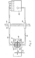
- F ig. 1 is a generic illustration of apparatus in accordance with the invention.
- the liquid whereof a variable quantity is to be monitored is contained in a container (not shown) remote from which are a switchbox 10 and an indicator panel 11 so disposed that light beams collected from an emitter 12 in the switchbox 10 by the individual fibres of a bundle of six optical fibres 13, 14, 15, 16, 17 and 18 pass into the container whence five of the light beams may selectively continue on to the indicator panel 11 and the sixth 18 returns to the switchbox 10 by way of a seventh optical fibre 19.
- a closed casing 20 of rectangular box shape Within the container, at an upper level therein, is.mounted a closed casing 20 of rectangular box shape.
- the six optical fibres 13 to 18 pass into the casing through a coupling 21 at the top and towards one side of the casing 20, and the five optical fibres 13 to 17 leave the casing through a coupling 22 at the top and towards the opposite side of the casing 20.
- the fibres 13 to 17 extend to different depths in the casing and have hori- z ontal stretches which are in a vertically-spaced series and are divided. to provide a parallel-sided gap 23.
- the fibre 18 has a horizontal stretch spaced above the others and which terminates at the entry side of the gap 23 to be continued at the other side of the gap by a short horizontal stretch of the seventh optical fibre 19 which has an upward return bend to a straight stretch extending across the gap 23 and closing same off from above prior to leaving the casing 20 through the coupling 21.
- the bundle of optical fibres 13 to 18 is contained in flexible armouring 24 between the coupling 21 and a coupling 25 through which said fibres pass into the switchbox 10.
- the bundle of optical fibres 13 to 17 is contained in flexible armouring 26 between the coupling 22 and a coupling 27 through which said fibres pass to the indicating panel 11.
- the colours green, yellow and red have the usual signification.
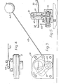
- a ; liquid container, one wall of which is shown at 30 in Fig. 2 has mounted therein a casing 31 into and from which extend a bundle 32 of five optical fibres 33 to 37 which passes through the container wall 30 from and to an external source/receiver 38 remote from the container.
- the bundle 32 of five optical fibres extends into and from a coupling 39 enabling the stretches of fibres external of the casing to be connected or disconnected.
- the bundle 32 of optical fibres is sheathed in flexible armouring 50.
- the bundle 32 of five optical fibres is separated into its constituent fibres 33 to 37 which have equi-spaced straight stretches intermediate which they are divided to provide a parallel-sided gap 40 through which an opaque plate 41 can swing.
- the plate 41 is mounted on a spindle 42 which extends out of the casing 31 through a sealing gland and is connected to an arm 43 which carries a float 44.
- the plate pivots upwards and successively interrupts the light beam trajectories across the gap along the individual optical fibres 33 to 37.
- the plate pivots and successively interrupts the light beam trajectories along the individual optical fibres, and, at each such interruption, the pertaining signal lamp at the receiver is extinguished.
- the plate 41 clears the gap where it divides the fifth optical fibre and the light beam resulting displays a red warning lamp.
- the apparatus hereinbefore described with reference to Figs. 2 to 7 is designed for use in the mining industry and provides safe and easily operated means. for monitoring the level of oil in a tank from a location remote from the machinery of which the tank forms part. Due to the coupling in the tank wall, the external optical fibre bunches can be disconnected when not required.
- the casing within which the plate and divided optical fibre paths are located is normally a fixture.in the tank though it can be removed as required.
Abstract
In a method of and apparatus for continual -remote ¦ monitoring of a local condition, such as the temperature, the : pressure, or the volume, of a liquid in a machine in operation ' and which includes one or more parts wherein liquid is contained and fulfils a function the success of which is contingent upon a variable quantity in a range departure from which is susceptible of interfering with, or at least impairing to a greater or lesser degree, the operation of the machine, light is transmitted by means of optical fibres (13 to 18) from a source (12) to light-responsive indicating means (11) along a trajectory passing through the liquid container, and there is mounted in the container an opaque plate (41) the position or attitude of which changes as the quantity to be monitored of the liquid varies such that a warning indication is given when said liquid quantity departs from said range.
The light is preferably split into a plurality of beams passing through the container such that the plate affects each beam in succession as said liquid quantity varies.
Preferably, the optical fibres are contained in a bundle outside the container and are divided into separate optical paths on each side of the plate within the container, the plate and the divided optical paths being contained in a closed casing (20) located within the liquid container.
Description
- This invention relates to apparatus for and a method of continual remote monttoring of a local condition, such as the temperature, the pressure, or the volume, of a liquid in a machine in operation and which includes one or more parts wherein liquid is contained and fulfils a function the success of which is contingent upon a variable quantity in a range departure from which is susceptible of interfering with, or at least impairing to a greater or lesser degree, the operation of the machine.
- . The invention is applicable, for example, to the continual monitoring of the oil level in the tank of mining machinery in operation.
- It is presently known to monitor such machinery oil levels by mechanical means, which is difficult to do, and by electrical means, which of course must be either flameproof or intrinsically safe. Thus both known forms of monitoring have disadvantages.
- An object of the present invention is to obviate or mitigate these disadvantages.
- In accordance with the present invention, a method of continual remote monitoring of a local condition of a liquid as aforesaid comprises transmitting light by means of optical fibres from a source to light-responsive indicating means along a trajectory passing through the liquid container, and mounting in the container an . opaque plate the position or attitude of which changes as the quantity to be monitored of the liquid varies such that a warning indication is given when said liquid-quantity departs from said range.
- Preferably, the light is split into a plurality of beams passing through the container such that the plate affects each beam in succession as said liquid quantity varies.
- Also, in accordance with the present invention apparatus for continual remote monotoring of a.local condition of a liquid as aforesaid comprises a light source, a light-responsive indicating means including a warning indicator, optical fibres transmitting light from the source to the indicating means along a trajectory passing through the liquid container,and an opaque plate mounted in the container in such manner that its position or attitude can change in response to variation of the quantity to be monitored of the liquid and the warning indicator is activated when said liquid quantity departs from said range.
- Preferably, the optical fibres produce within the container a plurality of light beams which are successively affected by said plate as the liquid quantity varies.
- Preferably also, the optical fibres are contained in a bundle outside the container, said fibres being divided into separate optical paths on each side of the plate within the container.
- Preferably also, the plate and the divided optical paths are contained in a closed casing located within the liquid container.
- Embodiments of the present invention will now be described, by way of example, with reference to the accompanying drawings, in which:-
- Fig. 1 is a diagrammatic view of apparatus for the continual remote monitoring of a local condition of a liquid as aforesaid;
- Fig. 2 is a diagrammatic view of apparatus for monitoring the liquid level in a container;
- Fig. 3 is an elevation of a casing within the container and mounting a plate for pivotal movement;
- Fig. 4 is a plan view of the casing;
- Fig. 5 is a sectional end elevation of the casing;
- Fig. 6 illustrates an optical fibre source and receiver, a connection into the liquid container and the plate casing: and
- Fig. 7 is a sectional side view of the casing.
- Fig. 1 is a generic illustration of apparatus in accordance with the invention. The liquid whereof a variable quantity is to be monitored is contained in a container (not shown) remote from which are a switchbox 10 and an indicator panel 11 so disposed that light beams collected from an
emitter 12 in the switchbox 10 by the individual fibres of a bundle of sixoptical fibres optical fibre 19. - Within the container, at an upper level therein, is.mounted a closed
casing 20 of rectangular box shape. The sixoptical fibres 13 to 18 pass into the casing through acoupling 21 at the top and towards one side of thecasing 20, and the fiveoptical fibres 13 to 17 leave the casing through acoupling 22 at the top and towards the opposite side of thecasing 20. Thefibres 13 to 17 extend to different depths in the casing and have hori- zontal stretches which are in a vertically-spaced series and are divided. to provide a parallel-sidedgap 23. The fibre 18 has a horizontal stretch spaced above the others and which terminates at the entry side of thegap 23 to be continued at the other side of the gap by a short horizontal stretch of the seventhoptical fibre 19 which has an upward return bend to a straight stretch extending across thegap 23 and closing same off from above prior to leaving thecasing 20 through thecoupling 21. The bundle ofoptical fibres 13 to 18 is contained inflexible armouring 24 between thecoupling 21 and acoupling 25 through which said fibres pass into the switchbox 10. Likewise the bundle ofoptical fibres 13 to 17 is contained inflexible armouring 26 between thecoupling 22 and acoupling 27 through which said fibres pass to the indicating panel 11. - The light beams travelling along the
optical fibres 13 to 17 from theemitter 12, provided they are not intercepted in thecasing 20, illuminate lamps at the indicating panel 11, the lamps then illuminated through thefibres fibre 13 displaying the colour yellow, and that illuminated through thefibre 14 displaying the colour red. The colours green, yellow and red have the usual signification. The light beam travelling along the optical fibre 18, if not interrupted in thecasing 20, crosses the gap and continues along theoptical fibre 19 back to the switchbox 10 wherein thefibre 19 is turned away from thefibres 13 to 18 and focuses white light on a photo-sensitive receiver 28 and maintains the supply for operation of the machine. - Referring now to Figs. 2 to 7 of the drawings, a ; liquid container, one wall of which is shown at 30 in Fig. 2 has mounted therein a
casing 31 into and from which extend abundle 32 of fiveoptical fibres 33 to 37 which passes through thecontainer wall 30 from and to an external source/receiver 38 remote from the container. At each passage through thecontainer wall 30 thebundle 32 of five optical fibres extends into and from acoupling 39 enabling the stretches of fibres external of the casing to be connected or disconnected. In practice, as illustrated in Fig. 6, thebundle 32 of optical fibres is sheathed inflexible armouring 50. - Within the
casing 31, thebundle 32 of five optical fibres is separated into itsconstituent fibres 33 to 37 which have equi-spaced straight stretches intermediate which they are divided to provide a parallel-sided gap 40 through which anopaque plate 41 can swing. - The
plate 41 is mounted on aspindle 42 which extends out of thecasing 31 through a sealing gland and is connected to anarm 43 which carries afloat 44. Thus, as the liquid level in the container falls the plate pivots upwards and successively interrupts the light beam trajectories across the gap along the individualoptical fibres 33 to 37. - In this embodiment, the four light beams to be first interrupted as the
plate 41 pivots upwards individually display the colour green at the receiver so that the level of liquid in the tank can be ascertained from the number of green lamps illuminated. As the liquid level dimishes the float is lowered, the plate pivots and successively interrupts the light beam trajectories along the individual optical fibres, and, at each such interruption, the pertaining signal lamp at the receiver is extinguished. When the level of the liquid in the container reaches a critical low, theplate 41 clears the gap where it divides the fifth optical fibre and the light beam resulting displays a red warning lamp. - In the simplest form provision is made for illumination of only one green lamp and the red lamp.
- The apparatus hereinbefore described with reference to Figs. 2 to 7 is designed for use in the mining industry and provides safe and easily operated means. for monitoring the level of oil in a tank from a location remote from the machinery of which the tank forms part. Due to the coupling in the tank wall, the external optical fibre bunches can be disconnected when not required. The casing within which the plate and divided optical fibre paths are located is normally a fixture.in the tank though it can be removed as required.
Claims (6)
- I. A method of continual remote monitoring of a local condition, such as the temperature, the pressure, or the volume, of a liquid in a machine in operation and which includes one or more parts wherein liquid is contained and fulfils a function the success of which is contingent upon a variable quantity in a range departure from which is susceptible of interfering with, or at least impairing to a greater or lesser degree, the operation of the machine, said method comprising transmitting light by means of optical fibres from a. source to light-responsive indicating means along a trajectory passing through the liquid container, and mounting in the container an opaque plate the position or attitude of which changes as the quantity to be monitored of the liquid varies such that a warning indication is given when said liquid quantity departs from said range.
- 2. A method as claimed in claim 1, in which the light is split into a plurality of beams passing through the container such that the plate affects each beam in succession as said liquid quantity varies.
- 3. Apparatus for continual remote monitoring of a local condition, such as the temperature, the pressure, or the volume, of a liquid in a machine in operation and which includes one or more parts wherein liquid is contained and fulfils a function the success of which is contingent upon a variable quantity in a range departure from which is susceptible of interfering with, or at least impairing to a greater or lesser degree, the operation of the machine, said apparatus comprising a light source, a light-responsive indicating means including a warning indicator, optical fibres transmitting light from the source to the indicating means along a trajectory passing through the liquid container, and an opaque plate mounted in the container in such manner that its position or attitude can change in response to variation of the quantity to be monitored of the liquid and the warning indicator is activated when said liquid quantity departs from said range..
- 4. Apparatus as claimed in claim 3, in which the optical fibres produce within the container a plurality of light beams which are successively affected by said plate as the liquid quantity varies.
- , 5. Apparatus as claimed in claim 3 or 4 in which the optical fibres are contained in a bundle outside the container, said fibres being divided into separate optical paths on each side of the plate within the container. -
- 6. Apparatus as claimed in claim 5, in which the plate and the divided optical paths are contained in a closed casing located within the liquid container.
Applications Claiming Priority (2)
| Application Number | Priority Date | Filing Date | Title |
|---|---|---|---|
| GB8104180 | 1981-02-11 | ||
| GB8104180 | 1981-02-11 |
Publications (2)
| Publication Number | Publication Date |
|---|---|
| EP0058056A2 true EP0058056A2 (en) | 1982-08-18 |
| EP0058056A3 EP0058056A3 (en) | 1985-01-23 |
Family
ID=10519603
Family Applications (1)
| Application Number | Title | Priority Date | Filing Date |
|---|---|---|---|
| EP82300566A Withdrawn EP0058056A3 (en) | 1981-02-11 | 1982-02-04 | Apparatus for and method of continual remote monitoring of a local condition of a liquid in a machine part |
Country Status (1)
| Country | Link |
|---|---|
| EP (1) | EP0058056A3 (en) |
Cited By (9)
| Publication number | Priority date | Publication date | Assignee | Title |
|---|---|---|---|---|
| US5174931A (en) * | 1988-09-26 | 1992-12-29 | 3D Systems, Inc. | Method of and apparatus for making a three-dimensional product by stereolithography |
| US5236637A (en) * | 1984-08-08 | 1993-08-17 | 3D Systems, Inc. | Method of and apparatus for production of three dimensional objects by stereolithography |
| US5257539A (en) * | 1992-05-21 | 1993-11-02 | Gale Danny E | Electronic oil level indicator |
| US5358673A (en) * | 1990-02-15 | 1994-10-25 | 3D Systems, Inc. | Applicator device and method for dispensing a liquid medium in a laser modeling machine |
| US5651934A (en) * | 1988-09-26 | 1997-07-29 | 3D Systems, Inc. | Recoating of stereolithographic layers |
| US5743135A (en) * | 1993-08-27 | 1998-04-28 | Vlsi Technology, Inc. | Optical-fiber liquid-level monitor |
| US5902537A (en) * | 1995-02-01 | 1999-05-11 | 3D Systems, Inc. | Rapid recoating of three-dimensional objects formed on a cross-sectional basis |
| GB2425830A (en) * | 2005-04-25 | 2006-11-08 | Boeing Co | Systems and methods for fluid level detection |
| EP2023098A1 (en) * | 2007-08-08 | 2009-02-11 | Delphi Technologies, Inc. | Light Sensing Contactless Fuel Level Sensor |
Citations (4)
| Publication number | Priority date | Publication date | Assignee | Title |
|---|---|---|---|---|
| US3466928A (en) * | 1967-09-15 | 1969-09-16 | Gen Motors Corp | Fiber optic liquid level indicator |
| DE2022995A1 (en) * | 1970-05-12 | 1971-12-02 | Daimler Benz Ag | Device for displaying the level of a liquid |
| DE2208931A1 (en) * | 1972-02-25 | 1973-09-06 | Grandi | ELECTRO-OPTICAL LEVEL INDICATOR, IN PARTICULAR FOR DISPLAYING THE LEVEL OF EASILY FLAMMABLE PRODUCTS IN CONTAINERS |
| GB2002905A (en) * | 1977-07-27 | 1979-02-28 | Northern Eng Ind | Liquid level indicator apparatus |
-
1982
- 1982-02-04 EP EP82300566A patent/EP0058056A3/en not_active Withdrawn
Patent Citations (4)
| Publication number | Priority date | Publication date | Assignee | Title |
|---|---|---|---|---|
| US3466928A (en) * | 1967-09-15 | 1969-09-16 | Gen Motors Corp | Fiber optic liquid level indicator |
| DE2022995A1 (en) * | 1970-05-12 | 1971-12-02 | Daimler Benz Ag | Device for displaying the level of a liquid |
| DE2208931A1 (en) * | 1972-02-25 | 1973-09-06 | Grandi | ELECTRO-OPTICAL LEVEL INDICATOR, IN PARTICULAR FOR DISPLAYING THE LEVEL OF EASILY FLAMMABLE PRODUCTS IN CONTAINERS |
| GB2002905A (en) * | 1977-07-27 | 1979-02-28 | Northern Eng Ind | Liquid level indicator apparatus |
Cited By (14)
| Publication number | Priority date | Publication date | Assignee | Title |
|---|---|---|---|---|
| US5236637A (en) * | 1984-08-08 | 1993-08-17 | 3D Systems, Inc. | Method of and apparatus for production of three dimensional objects by stereolithography |
| US5891382A (en) * | 1988-09-26 | 1999-04-06 | 3D System, Inc. | Recoating of stereolithographic layers |
| US6048487A (en) * | 1988-09-26 | 2000-04-11 | 3D Systems, Inc. | Recoating stereolithographic layers |
| US5174931A (en) * | 1988-09-26 | 1992-12-29 | 3D Systems, Inc. | Method of and apparatus for making a three-dimensional product by stereolithography |
| US5651934A (en) * | 1988-09-26 | 1997-07-29 | 3D Systems, Inc. | Recoating of stereolithographic layers |
| US5358673A (en) * | 1990-02-15 | 1994-10-25 | 3D Systems, Inc. | Applicator device and method for dispensing a liquid medium in a laser modeling machine |
| US5257539A (en) * | 1992-05-21 | 1993-11-02 | Gale Danny E | Electronic oil level indicator |
| US5743135A (en) * | 1993-08-27 | 1998-04-28 | Vlsi Technology, Inc. | Optical-fiber liquid-level monitor |
| US5902537A (en) * | 1995-02-01 | 1999-05-11 | 3D Systems, Inc. | Rapid recoating of three-dimensional objects formed on a cross-sectional basis |
| GB2425830A (en) * | 2005-04-25 | 2006-11-08 | Boeing Co | Systems and methods for fluid level detection |
| GB2425830B (en) * | 2005-04-25 | 2007-07-11 | Boeing Co | Systems and methods for fluid level detection |
| US7259384B2 (en) | 2005-04-25 | 2007-08-21 | The Boeing Company | Fluid level optical detector with float having opaque and transmissive portions |
| EP2023098A1 (en) * | 2007-08-08 | 2009-02-11 | Delphi Technologies, Inc. | Light Sensing Contactless Fuel Level Sensor |
| US7677098B2 (en) | 2007-08-08 | 2010-03-16 | Delphi Technologies, Inc. | Light sensing contactless fuel level sensor |
Also Published As
| Publication number | Publication date |
|---|---|
| EP0058056A3 (en) | 1985-01-23 |
Similar Documents
| Publication | Publication Date | Title |
|---|---|---|
| US3548657A (en) | Device for an outside display of the level of a liquid contained within a tank | |
| EP0058056A2 (en) | Apparatus for and method of continual remote monitoring of a local condition of a liquid in a machine part | |
| US4440022A (en) | Liquid-level detection | |
| US3272174A (en) | Remote level indication | |
| EP1621863B1 (en) | Device for detecting a leakage | |
| JP2000502184A (en) | Display device | |
| US6182601B1 (en) | Meter with microprocessor control of pointer and multi-status indicator | |
| CN102667423A (en) | Light enhanced flow tube | |
| US4777480A (en) | Multi-scale indicator | |
| EP0381894A1 (en) | Sight gauge installation for the remote sensing of a liquid-level | |
| US4806902A (en) | Fluid level monitor and filler assembly | |
| US5257539A (en) | Electronic oil level indicator | |
| US1728929A (en) | Combustion indicator | |
| US3002186A (en) | Oil gauge | |
| US3781858A (en) | Fluid level monitoring system | |
| US2369798A (en) | Water gauge | |
| US4244317A (en) | Bargraph light guide | |
| US1532995A (en) | Level indicator of the luminous type | |
| CA1109572A (en) | Device for the display of data representative of qualities | |
| GB2171796A (en) | Liquid level sensor | |
| JPS649032A (en) | Transportation device | |
| US2678431A (en) | Control panel display system | |
| US2174700A (en) | Liquid level indicator | |
| US2683372A (en) | Fluid level indicating gauge | |
| US4854351A (en) | Contact bar for the warp stop motion |
Legal Events
| Date | Code | Title | Description |
|---|---|---|---|
| PUAI | Public reference made under article 153(3) epc to a published international application that has entered the european phase |
Free format text: ORIGINAL CODE: 0009012 |
|
| AK | Designated contracting states |
Designated state(s): DE FR GB |
|
| RAP1 | Party data changed (applicant data changed or rights of an application transferred) |
Owner name: ANDERSON STRATHCLYDE PLC |
|
| PUAL | Search report despatched |
Free format text: ORIGINAL CODE: 0009013 |
|
| STAA | Information on the status of an ep patent application or granted ep patent |
Free format text: STATUS: THE APPLICATION HAS BEEN WITHDRAWN |
|
| AK | Designated contracting states |
Designated state(s): DE FR GB |
|
| 18W | Application withdrawn |
Withdrawal date: 19850108 |
|
| RIN1 | Information on inventor provided before grant (corrected) |
Inventor name: MACKIE, KENMUIR Inventor name: SPEIRS, ALISDAIR BLAIR HISLOP |