EP0058065A2 - Apparatus for developing a latent image - Google Patents
Apparatus for developing a latent image Download PDFInfo
- Publication number
- EP0058065A2 EP0058065A2 EP82300590A EP82300590A EP0058065A2 EP 0058065 A2 EP0058065 A2 EP 0058065A2 EP 82300590 A EP82300590 A EP 82300590A EP 82300590 A EP82300590 A EP 82300590A EP 0058065 A2 EP0058065 A2 EP 0058065A2
- Authority
- EP
- European Patent Office
- Prior art keywords
- belt
- development zone
- latent image
- developer material
- rigid member
- Prior art date
- Legal status (The legal status is an assumption and is not a legal conclusion. Google has not performed a legal analysis and makes no representation as to the accuracy of the status listed.)
- Granted
Links
Images
Classifications
-
- G—PHYSICS
- G03—PHOTOGRAPHY; CINEMATOGRAPHY; ANALOGOUS TECHNIQUES USING WAVES OTHER THAN OPTICAL WAVES; ELECTROGRAPHY; HOLOGRAPHY
- G03G—ELECTROGRAPHY; ELECTROPHOTOGRAPHY; MAGNETOGRAPHY
- G03G15/00—Apparatus for electrographic processes using a charge pattern
- G03G15/06—Apparatus for electrographic processes using a charge pattern for developing
- G03G15/08—Apparatus for electrographic processes using a charge pattern for developing using a solid developer, e.g. powder developer
- G03G15/0806—Apparatus for electrographic processes using a charge pattern for developing using a solid developer, e.g. powder developer on a donor element, e.g. belt, roller
- G03G15/0813—Apparatus for electrographic processes using a charge pattern for developing using a solid developer, e.g. powder developer on a donor element, e.g. belt, roller characterised by means in the developing zone having an interaction with the image carrying member, e.g. distance holders
-
- G—PHYSICS
- G03—PHOTOGRAPHY; CINEMATOGRAPHY; ANALOGOUS TECHNIQUES USING WAVES OTHER THAN OPTICAL WAVES; ELECTROGRAPHY; HOLOGRAPHY
- G03G—ELECTROGRAPHY; ELECTROPHOTOGRAPHY; MAGNETOGRAPHY
- G03G15/00—Apparatus for electrographic processes using a charge pattern
- G03G15/06—Apparatus for electrographic processes using a charge pattern for developing
- G03G15/08—Apparatus for electrographic processes using a charge pattern for developing using a solid developer, e.g. powder developer
- G03G15/09—Apparatus for electrographic processes using a charge pattern for developing using a solid developer, e.g. powder developer using magnetic brush
-
- G—PHYSICS
- G03—PHOTOGRAPHY; CINEMATOGRAPHY; ANALOGOUS TECHNIQUES USING WAVES OTHER THAN OPTICAL WAVES; ELECTROGRAPHY; HOLOGRAPHY
- G03G—ELECTROGRAPHY; ELECTROPHOTOGRAPHY; MAGNETOGRAPHY
- G03G2215/00—Apparatus for electrophotographic processes
- G03G2215/06—Developing structures, details
- G03G2215/0602—Developer
- G03G2215/0604—Developer solid type
- G03G2215/0607—Developer solid type two-component
-
- G—PHYSICS
- G03—PHOTOGRAPHY; CINEMATOGRAPHY; ANALOGOUS TECHNIQUES USING WAVES OTHER THAN OPTICAL WAVES; ELECTROGRAPHY; HOLOGRAPHY
- G03G—ELECTROGRAPHY; ELECTROPHOTOGRAPHY; MAGNETOGRAPHY
- G03G2215/00—Apparatus for electrophotographic processes
- G03G2215/06—Developing structures, details
- G03G2215/0634—Developing device
- G03G2215/0636—Specific type of dry developer device
- G03G2215/0648—Two or more donor members
Definitions
- This invention relates to an apparatus for developing a latent image and to an electrophotographic printing machine incorporating same.
- an electrophotographic printing machine includes a photoconductive member which is charged to a substantially uniform potential to sensitize the surface thereof.
- the charged portion of the photoconductive member is exposed to a light image of an original document being reproduced.
- the latent image is developed by bringing a developer material into contact therewith.. This forms a powder image on the photoconductive member which is subsequently transferred to a copy sheet. Finally, the copy sheet is heated to permanently affix the powder image thereto in image configuration.
- the developer material is made from a mixture of carrier granules and toner particles.
- the toner particles adhere triboelectrically to the carrier granules.
- This two component mixture is brought into contact with the latent image.
- Toner particles are attracted from the carrier granules to the latent image forming a toner powder image thereof.
- Different techniques have been employed to improve development of the latent image. For example, cascade systems, fur brush systems, magnetic brush systems and combinations of these systems have heretofore been utilized in electrophotographic printing machines.
- Armstrong et al. discloses an electrophotographic printing machine having a magnetic brush developer roller contacting one side of a flexible photoconductive belt. As shown in Figure 3, guide rollers maintain a portion of the belt in a slackened condition in the development zone so that the belt is capable of movement freely toward and away from the developer roller in response to the varying contours thereof.
- Swapceinski describes an electrophotographic printing machine including a gimbled back-up roller engaging the backside of a photoconductive belt.
- the back-up roller is opposed from the developer roller to compensate for relative changes in the thickness of the developer material on the developer roller, as well as maintaining constant pressure in the nip between the developer roller and photoconductive belt.
- Kopko et al. describes an electrophotographic printing machine in which developer material on a developer roller deforms a tensioned photoconductive belt so as to space the developer roller from the belt.
- an insulating two component developer material is contained in a highly agitated development zone. This permits the continual development of high quality images including solid areas.
- Hatch discloses an electrophotographic printing machine in which developer material on a developer roller spaces the photoconductive belt therefrom.
- the thickness of the layer of developer material on the developer roller is adjustable to control the spacing between the photoconductive belt and the developer roller.
- an apparatus for developing a latent image recorded on a rigid member Flexible means, positioned closely adjacent to the rigid member defining a development zone therebetween, transport developer material into contact with the rigid member in the development zone. Means are provided for maintaining the flexible means at a preselected tension of sufficient magnitude to compress the developer material being transported into contact with the rigid member and to space the flexible means therefrom.
- the illustrative electrophotographic printing machine employs a drum 10 having a photoconductive surface 12.
- photoconductive surface 12 comprises a selenium alloy adhering to a conductive substrate.
- Drum 10 moves in the direction of arrow 14 to advance photoconductive surface 12 sequentially through the various processing stations disposed about the path of movement thereof.
- a corona generating device indicated generally by the reference numeral 16 charges photoconductive surface 12 to a relatively high substantially uniform potential.
- Exposure station B includes an exposure system, indicated generally by the reference numeral 18.
- Exposure system 18 an original document is positioned facedown upon a transparent platen. Light rays reflected from the original document are transmitted through a lens to form a light image thereof. The light image is focused on the charged portion of photoconductive surface 12 to selectively dissipate the charge thereon. This records an electrostatic latent image on photoconductive surface 12 which corresponds to the informational areas contained within the original document.
- drum 10 advances the electrostatic latent image recorded on photoconductive surface 12 to development station C.
- a magnetic brush development system indicated generally by the reference numeral 20
- the latent image attracts the toner particles from the carrier granules of the developer material to form a toner powder image on photoconductive surface 12 of drum 10.
- the detailed structure of development system 20 will be described hereinafter with reference to Figures 2 and 3.
- Drum 10 then advances the toner powder image to transfer station D.
- a sheet of support material is moved into contact with the powder image.
- the sheet of support material is advanced to transfer station D by a sheet feeding apparatus, indicated generally by the reference numeral 22.
- sheet feeding apparatus 22 includes a feed roll 24 contacting the uppermost sheet of a stack of sheets 26.
- Feed roll 24 rotates in the direction of arrow 28 so as to advance the uppermost sheet into the nip defined by forwarding rollers 30.
- Forwarding rollers 30 rotate in the direction of arrow 32 to advance the sheet into chute 34.
- Chute 34 directs the advancing sheet of support material into contact with photoconductive surface 12 of drum 10 so that. the toner powder image developed thereon contacts the advancing sheet at transfer station D.
- transfer station D includes a corona generating device 36 which sprays ions onto the back side of the sheet. This attracts the toner powder image from photoconductive surface 12 to the sheet. After transfer, the sheet continues to move in the direction of arrow 38 onto a conveyor 40 which advances the sheet to fusing station E.
- a corona generating device 36 which sprays ions onto the back side of the sheet. This attracts the toner powder image from photoconductive surface 12 to the sheet. After transfer, the sheet continues to move in the direction of arrow 38 onto a conveyor 40 which advances the sheet to fusing station E.
- Fusing station E includes a fuser assembly, indicated generally by the reference numeral 42, which permanently affixes the transferred toner powder image to the sheet.
- fuser assembly 42 includes a heated fuser roller 44 and a backup roller 46. The sheet passes between fuser roller 44 and backup roller 46 with the toner powder image contacting fuser roller 44. In this manner, the toner powder image is permanently affixed to the sheet.
- forwarding rollers 48 advance the sheet to catch tray 50 for subsequent removal from the printing machine by the operator.
- cleaning station F includes a rotatably mounted brush in contact with the photoconductive surface. The particles are cleaned from the photoconductive surface by the rotation of the brush in contact therewith. Subsequent to cleaning, a discharge lamp floods photocor ; '.ive surface 12 with light to dissipate any residual electrostatic charge remaining thereon prior to the charging thereof for the next successive imaging cycle.
- development system 20 includes a housing 52 defining a chamber for storing a supply of developer material therein.
- a cylindrical member 54 mounted rotatably in the chamber of housing 52, includes a plurality of vanes extending outwardly therefrom so as to act as a paddle wheel when rotating in the direction of arrow 56. In this way, cylindrical member 54 advances the developer material to developer belt 58.
- a metering blade 60 is positioned closely adjacent to developer belt 58 defining a gap therebetween through which the developer material passes. This gap regulates the quantity of developer material being advanced into development zone 62 as developer belt 58 moves in the direction of arrow 64.
- one end portion of metering blade 60 extends in a longitudinal direction extending substantially across the width of belt 58 so as to provide a uniform gap controlling the quantity of developer material being moved into development zone 62.
- the other end portion of metering blade 60 is secured to development housing 52.
- Belt 58 is entrained about opposed, spaced magnetic rollers, indicated generally by the reference numerals 66 and 68.
- Magnetic rollers 66 and 68 are substantially identical to one another with magnetic roller 68 being positioned in the entrance to the development zone 62 and magnetic roller 66 being located in the exit zone of development zone 62.
- magnetic roller 66 is mounted resiliently to tension belt 58.
- Magnetic roller 66 includes a non-magnetic tubular roll 70 journaled for rotation.
- tubular roll 70 is made from aluminum.
- An elongated magnet 72 is positioned concentrically within tubular roll 70 being spaced from -the interior circumferential surface thereof.
- Magnet 72 has a plurality of magnetic poles impressed thereon.
- magnet 72 is made from barium ferrite. No magnetic poles are impressed on magnet 72 in the region adjacent the development zone 62. In this way, the magnetic poles generate a strong magnetic field in the development zone entrance and a weak or substantially no magnetic field in the development zone itself. The strength of the magnetic field in the development zone is preferably less than 100 gauss.
- magnetic roller 66 includes a tubular roll 74 having an elongated magnet disposed concentrically therein and spaced therefrom.
- Tubular roll 74 is also made from aluminum with magnet 76 being made from barium ferrite. Magnet 76 has a plurality of magnetic poles impressed thereon with the region adjacent the development zone having substantially no magnetic poles.
- the exit region of the development zone has a strong magnetic field with the development zone itself having a weak magnetic field. It is thus clear that both the exit and entrance regions to the development zone have strong magnetic fields with the development zone itself having a substantially weaker magnetic field.
- the development zone is a field free region.
- a motor (not shown) rotates tubular member 70 to advance belt 58 in the direction of arrow 64.
- Tubular member 74 is journaled to rotate freely and acts as an idler roller.
- developer material is attracted to the surface thereof.
- the developer material is advanced on belt 58 into contact with the photoconductive surface 12 of drum 10 in development zone 62.
- the compressed pile height of the developer material in development zone 62 ranges from about 0.04 centimeters to about 0.15 centimeters.
- the brush of developer material in development zone 62 causes belt 58 to deflect.
- belt 58 is deflected in development zone 62 so as to form an arc about drum 10.
- the deflection arc ranges from about 10° to about 40°.
- the toner particles are attracted from the carrier granules to the electrostatic latent image forming a toner powder image on photoconductive surface 12.
- belt 58 is made from a flexible conductive web such as Mylar having a conductive textured coating thereon.
- Belt 58 is electrically biased by a voltage source (not shown) to a suitable polarity and magnitude, preferably to a level intermediate that of background voltage level and the image voltage level recorded on the photoconductive surface of belt 10.
- the voltage source preferably electrically biases belt 58 to a voltage ranging from about 50 volts to about 350 volts.
- the unused developer material and denuded carrier granules fall from belt 58 back to the chamber of housing 52. These materials are intermingled with fresh developer material and additional toner particles to form a new supply of developer ' -terial which is advanced by cylindrical member 54 onto belt 58. Additional toner particles may be furnished to developer housing 52 by an externally mounted toner supply housing (not shown). The housing periodically furnishes additional toner particles to the developer material when the concentration thereof is below a prescribed level.
- the developer material includes carrier granules having a ferromagnetic core overcoated with a non-continuous layer of resinous material.
- Suitable resins include poly(vinylidenefluoride) and poly(vinylidene fluorodeco-tetrafluorethylene).
- the developer materials can be prepared by mixing the carrier granules with the toner particles. Generally, any of the toner particles known in the art are suitable for mixing with the carrier granules. Suitable toner particles are prepared by finely grinding a resinous material and mixing it with coloring material.
- the resinous material may be a vinyl polymer such as a polyvinyl chloride, polyvinylidene chloride, polyvinyl acetate, polyvinyl acetals, polyvinyl ether and poly acrylic.
- Suitable coloring materials may be amongst others chromegen black and solvent black.
- the developer material comprises about 95 to about 99% by weight of carrier granules and from about 5% to about 1% by weight of toner particles.
- roller 66 is mounted in suitable bearings in a yoke, indicated generally by the reference numeral 78.
- yoke 78 includes a U-shaped portion supporting roller 66 and a rod 80 secured to the midpoint of the cross member of U-shaped member 78.
- Coil spring 82 is wrapped around rod 80.
- Rod 80 is mounted slidably in frame 84 secured fixedly to developer housing 52.
- Spring 82 is compressed between yoke 78 and frame 84. Compressed spring 82 resiliently urges yoke 78 and, in turn, roller 66 against belt 58.
- Spring 82 is designed to have an appropriate spring constant such that when placed under the desired compression, belt 58 is tensioned to about 0.1 kilogram per linear centimeter. Belt 58 is maintained under a sufficiently low tension to enable the developer material disposed in development zone 62 ( Figure 2) to deflect belt 58 through an arc ranging from about 10°. to about 40°. This extended arc comprises development zone 62 ( Figure 2).
- the development apparatus of the present invention has a developer belt positioned closely adjacent to a rigid photoconductive drum so as to transport developer material into contact with the electrostatic latent image recorded thereon.
- the belt is maintained at a pre-selected tension of sufficient magnitude to enable the developer material being transported into contact with the photoconductive drum to deflect the belt in the development zone. In this manner, the belt deflects to define an . extended development zone which significantly improves development of the electrostatic latent image.
Abstract
Description
- This invention relates to an apparatus for developing a latent image and to an electrophotographic printing machine incorporating same.
- Generally, an electrophotographic printing machine includes a photoconductive member which is charged to a substantially uniform potential to sensitize the surface thereof. The charged portion of the photoconductive member is exposed to a light image of an original document being reproduced. This records an electrostatic latent image on the photoconductive member corresponding to the informational areas contained within the original document. After recording the electrostatic latent image on the photoconductive member, the latent image is developed by bringing a developer material into contact therewith.. This forms a powder image on the photoconductive member which is subsequently transferred to a copy sheet. Finally, the copy sheet is heated to permanently affix the powder image thereto in image configuration.
- Frequently, the developer material is made from a mixture of carrier granules and toner particles. The toner particles adhere triboelectrically to the carrier granules. This two component mixture is brought into contact with the latent image. Toner particles are attracted from the carrier granules to the latent image forming a toner powder image thereof. Hereinbefore, it has been difficult to develop both the large solid areas and fine lines of the latent image. Different techniques have been employed to improve development of the latent image. For example, cascade systems, fur brush systems, magnetic brush systems and combinations of these systems have heretofore been utilized in electrophotographic printing machines. However, in all of the foregoing types of systems there continues to exist the problem of achieving uniform development for both the fine lines and large solid areas of the latent image. It has been extremely difficult to develop both the fine line image areas as well as the larger solid area while maintaining a minimum background density. Development can be improved by reducing the spacing between the photoconductive surface and the development system. However, in the case of rigid photoconductive members this is limited by the expense of reducing the tolerance accumulation between the rigid photoconductive member and the development system.
- Various approaches have been devised to improve development. T' following disclosures appear to be relevant:
- U.S. Patent No. 4,013,041 Patentee: Armstrong et al. Issued: March 22, 1977
- Research Disclosure Journal July, 1979 Page 352, No. 18318 Disclosed By: Swapceinski
- Co-pending U.S. Patent Application Serial No. 111,450 Filed: January 11, 1980 Applicant: Kopko et al.
- Co-pending U.S. Patent Application Serial No. 155,889 Filed: June 2, 1980 Applicant: Hays
- Co-pending U.S. Patent Application Serial No. 169,543 Filed: July 17,1980 Applicant: Hatch
- The pertinent portions of the foregoing disclosures may be briefly summarized as follows:
- Armstrong et al. discloses an electrophotographic printing machine having a magnetic brush developer roller contacting one side of a flexible photoconductive belt. As shown in Figure 3, guide rollers maintain a portion of the belt in a slackened condition in the development zone so that the belt is capable of movement freely toward and away from the developer roller in response to the varying contours thereof.
- Swapceinski describes an electrophotographic printing machine including a gimbled back-up roller engaging the backside of a photoconductive belt. The back-up roller is opposed from the developer roller to compensate for relative changes in the thickness of the developer material on the developer roller, as well as maintaining constant pressure in the nip between the developer roller and photoconductive belt.
- Kopko et al. describes an electrophotographic printing machine in which developer material on a developer roller deforms a tensioned photoconductive belt so as to space the developer roller from the belt.
- In Hays, an insulating two component developer material is contained in a highly agitated development zone. This permits the continual development of high quality images including solid areas.
- Hatch discloses an electrophotographic printing machine in which developer material on a developer roller spaces the photoconductive belt therefrom. The thickness of the layer of developer material on the developer roller is adjustable to control the spacing between the photoconductive belt and the developer roller.
- In accordance with the features of the present invention, there is provided an apparatus for developing a latent image recorded on a rigid member. Flexible means, positioned closely adjacent to the rigid member defining a development zone therebetween, transport developer material into contact with the rigid member in the development zone. Means are provided for maintaining the flexible means at a preselected tension of sufficient magnitude to compress the developer material being transported into contact with the rigid member and to space the flexible means therefrom.
- Other aspects of the present invention will become apparent as the following description proceeds and upon reference to the drawings, in which:
- Figure 1 is a schematic elevational view depicting an electrophotographic printing machine incorporating the features of the present invention therein;
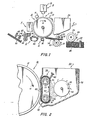
- Figure 2 is an elevational view illustrating the development system used in the Figure 1 printing machine; and
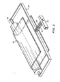
- Figure 3 is a fragmentary, perspective view showing the belt tensioning arrangement for the Figure 2 development system.
- As shown in Figure 1, the illustrative electrophotographic printing machine employs a
drum 10 having aphotoconductive surface 12. Preferably,photoconductive surface 12 comprises a selenium alloy adhering to a conductive substrate.Drum 10 moves in the direction ofarrow 14 to advancephotoconductive surface 12 sequentially through the various processing stations disposed about the path of movement thereof. - Initially, a portion of
photoconductive surface 12 passes through charging station A. At charging station A, a corona generating device, indicated generally by thereference numeral 16, chargesphotoconductive surface 12 to a relatively high substantially uniform potential. - Next, the charged portion of
photoconductive surface 12 is advanced through exposure station B. Exposure station B includes an exposure system, indicated generally by thereference numeral 18. Atexposure system 18, an original document is positioned facedown upon a transparent platen. Light rays reflected from the original document are transmitted through a lens to form a light image thereof. The light image is focused on the charged portion ofphotoconductive surface 12 to selectively dissipate the charge thereon. This records an electrostatic latent image onphotoconductive surface 12 which corresponds to the informational areas contained within the original document. - -Thereafter,
drum 10 advances the electrostatic latent image recorded onphotoconductive surface 12 to development station C. At development station C, a magnetic brush development system, indicated generally by thereference numeral 20, advances developer material into contact with the electrostatic latent image. The latent image attracts the toner particles from the carrier granules of the developer material to form a toner powder image onphotoconductive surface 12 ofdrum 10. The detailed structure ofdevelopment system 20 will be described hereinafter with reference to Figures 2 and 3. -
Drum 10 then advances the toner powder image to transfer station D. At transfer station D, a sheet of support material is moved into contact with the powder image. The sheet of support material is advanced to transfer station D by a sheet feeding apparatus, indicated generally by thereference numeral 22. Preferably,sheet feeding apparatus 22 includes afeed roll 24 contacting the uppermost sheet of a stack ofsheets 26.Feed roll 24 rotates in the direction ofarrow 28 so as to advance the uppermost sheet into the nip defined byforwarding rollers 30.Forwarding rollers 30 rotate in the direction ofarrow 32 to advance the sheet intochute 34.Chute 34 directs the advancing sheet of support material into contact withphotoconductive surface 12 ofdrum 10 so that. the toner powder image developed thereon contacts the advancing sheet at transfer station D. - Preferably, transfer station D includes a
corona generating device 36 which sprays ions onto the back side of the sheet. This attracts the toner powder image fromphotoconductive surface 12 to the sheet. After transfer, the sheet continues to move in the direction ofarrow 38 onto aconveyor 40 which advances the sheet to fusing station E. - Fusing station E includes a fuser assembly, indicated generally by the reference numeral 42, which permanently affixes the transferred toner powder image to the sheet. Preferably, fuser assembly 42 includes a
heated fuser roller 44 and abackup roller 46. The sheet passes betweenfuser roller 44 andbackup roller 46 with the toner powder image contactingfuser roller 44. In this manner, the toner powder image is permanently affixed to the sheet. After fusing, forwardingrollers 48 advance the sheet to catchtray 50 for subsequent removal from the printing machine by the operator. - Invariably, after the sheet of support material is separated from the
photoconductive surface 12 withdrum 10, some residual particles remain adhering thereto. These residual particles are removed fromphotoconductive surface 12 at cleaning station F. Preferably, cleaning station F includes a rotatably mounted brush in contact with the photoconductive surface. The particles are cleaned from the photoconductive surface by the rotation of the brush in contact therewith. Subsequent to cleaning, a discharge lamp floods photocor ; '.ive surface 12 with light to dissipate any residual electrostatic charge remaining thereon prior to the charging thereof for the next successive imaging cycle. - It is believed that the foregoing description is sufficient for purposes of the present application to illustrate the general operation of an electrophotographic printing machine incorporating the features of the present invention therein.
- Referring now to the specific subject matter of the present invention, as shown in Figure 2,
development system 20 includes ahousing 52 defining a chamber for storing a supply of developer material therein. Acylindrical member 54, mounted rotatably in the chamber ofhousing 52, includes a plurality of vanes extending outwardly therefrom so as to act as a paddle wheel when rotating in the direction ofarrow 56. In this way,cylindrical member 54 advances the developer material todeveloper belt 58. A metering blade 60 is positioned closely adjacent todeveloper belt 58 defining a gap therebetween through which the developer material passes. This gap regulates the quantity of developer material being advanced intodevelopment zone 62 asdeveloper belt 58 moves in the direction ofarrow 64. Preferably, one end portion of metering blade 60 extends in a longitudinal direction extending substantially across the width ofbelt 58 so as to provide a uniform gap controlling the quantity of developer material being moved intodevelopment zone 62. The other end portion of metering blade 60 is secured todevelopment housing 52.Belt 58 is entrained about opposed, spaced magnetic rollers, indicated generally by thereference numerals Magnetic rollers magnetic roller 68 being positioned in the entrance to thedevelopment zone 62 andmagnetic roller 66 being located in the exit zone ofdevelopment zone 62. Preferably,magnetic roller 66 is mounted resiliently totension belt 58.Magnetic roller 66 includes a non-magnetictubular roll 70 journaled for rotation. By way of example,tubular roll 70 is made from aluminum. Anelongated magnet 72 is positioned concentrically withintubular roll 70 being spaced from -the interior circumferential surface thereof.Magnet 72 has a plurality of magnetic poles impressed thereon. Preferably,magnet 72 is made from barium ferrite. No magnetic poles are impressed onmagnet 72 in the region adjacent thedevelopment zone 62. In this way, the magnetic poles generate a strong magnetic field in the development zone entrance and a weak or substantially no magnetic field in the development zone itself. The strength of the magnetic field in the development zone is preferably less than 100 gauss. Similarly,magnetic roller 66 includes atubular roll 74 having an elongated magnet disposed concentrically therein and spaced therefrom.Tubular roll 74 is also made from aluminum withmagnet 76 being made from barium ferrite.Magnet 76 has a plurality of magnetic poles impressed thereon with the region adjacent the development zone having substantially no magnetic poles. Thus, the exit region of the development zone has a strong magnetic field with the development zone itself having a weak magnetic field. It is thus clear that both the exit and entrance regions to the development zone have strong magnetic fields with the development zone itself having a substantially weaker magnetic field. Preferably, the development zone is a field free region. A motor (not shown) rotatestubular member 70 to advancebelt 58 in the direction ofarrow 64.Tubular member 74 is journaled to rotate freely and acts as an idler roller. Asbelt 58 moves in the direction ofarrow 64, developer material is attracted to the surface thereof. The developer material is advanced onbelt 58 into contact with thephotoconductive surface 12 ofdrum 10 indevelopment zone 62. The compressed pile height of the developer material indevelopment zone 62 ranges from about 0.04 centimeters to about 0.15 centimeters. The brush of developer material indevelopment zone 62 causesbelt 58 to deflect. Preferably,belt 58 is deflected indevelopment zone 62 so as to form an arc aboutdrum 10. The deflection arc ranges from about 10° to about 40°. In the development zone, the toner particles are attracted from the carrier granules to the electrostatic latent image forming a toner powder image onphotoconductive surface 12. Preferably,belt 58 is made from a flexible conductive web such as Mylar having a conductive textured coating thereon.Belt 58 is electrically biased by a voltage source (not shown) to a suitable polarity and magnitude, preferably to a level intermediate that of background voltage level and the image voltage level recorded on the photoconductive surface ofbelt 10. By way of example, the voltage source preferably electricallybiases belt 58 to a voltage ranging from about 50 volts to about 350 volts. - After the electrostatic latent image has been developed, the unused developer material and denuded carrier granules fall from
belt 58 back to the chamber ofhousing 52. These materials are intermingled with fresh developer material and additional toner particles to form a new supply of developer ' -terial which is advanced bycylindrical member 54 ontobelt 58. Additional toner particles may be furnished todeveloper housing 52 by an externally mounted toner supply housing (not shown). The housing periodically furnishes additional toner particles to the developer material when the concentration thereof is below a prescribed level. - Preferably, the developer material includes carrier granules having a ferromagnetic core overcoated with a non-continuous layer of resinous material. Suitable resins include poly(vinylidenefluoride) and poly(vinylidene fluorodeco-tetrafluorethylene). The developer materials can be prepared by mixing the carrier granules with the toner particles. Generally, any of the toner particles known in the art are suitable for mixing with the carrier granules. Suitable toner particles are prepared by finely grinding a resinous material and mixing it with coloring material. By way of example, the resinous material may be a vinyl polymer such as a polyvinyl chloride, polyvinylidene chloride, polyvinyl acetate, polyvinyl acetals, polyvinyl ether and poly acrylic. Suitable coloring materials may be amongst others chromegen black and solvent black. The developer material comprises about 95 to about 99% by weight of carrier granules and from about 5% to about 1% by weight of toner particles. These and other materials are disclosed in U.S. Patent No. 4,076,857 issued to Kasper et al. in 1978, the relevant portions thereof being hereby incorporated into the present application.
- Referring now to Figure 3, there is shown a system for tensioning
belt 58 in greater detail. As shown thereat,roller 66 is mounted in suitable bearings in a yoke, indicated generally by thereference numeral 78. Preferably,yoke 78 includes a U-shapedportion supporting roller 66 and arod 80 secured to the midpoint of the cross member ofU-shaped member 78.Coil spring 82 is wrapped aroundrod 80.Rod 80 is mounted slidably inframe 84 secured fixedly todeveloper housing 52.Spring 82 is compressed betweenyoke 78 andframe 84.Compressed spring 82 resiliently urgesyoke 78 and, in turn,roller 66 againstbelt 58.Spring 82 is designed to have an appropriate spring constant such that when placed under the desired compression,belt 58 is tensioned to about 0.1 kilogram per linear centimeter.Belt 58 is maintained under a sufficiently low tension to enable the developer material disposed in development zone 62 (Figure 2) to deflectbelt 58 through an arc ranging from about 10°. to about 40°. This extended arc comprises development zone 62 (Figure 2). - In recapitulation, it is clear that the development apparatus of the present invention has a developer belt positioned closely adjacent to a rigid photoconductive drum so as to transport developer material into contact with the electrostatic latent image recorded thereon. The belt is maintained at a pre-selected tension of sufficient magnitude to enable the developer material being transported into contact with the photoconductive drum to deflect the belt in the development zone. In this manner, the belt deflects to define an . extended development zone which significantly improves development of the electrostatic latent image.
Claims (9)
Applications Claiming Priority (2)
| Application Number | Priority Date | Filing Date | Title |
|---|---|---|---|
| US06/231,644 US4370056A (en) | 1981-02-05 | 1981-02-05 | Development system |
| US231644 | 1999-01-15 |
Publications (3)
| Publication Number | Publication Date |
|---|---|
| EP0058065A2 true EP0058065A2 (en) | 1982-08-18 |
| EP0058065A3 EP0058065A3 (en) | 1982-09-08 |
| EP0058065B1 EP0058065B1 (en) | 1985-06-05 |
Family
ID=22870094
Family Applications (1)
| Application Number | Title | Priority Date | Filing Date |
|---|---|---|---|
| EP82300590A Expired EP0058065B1 (en) | 1981-02-05 | 1982-02-05 | Apparatus for developing a latent image |
Country Status (5)
| Country | Link |
|---|---|
| US (1) | US4370056A (en) |
| EP (1) | EP0058065B1 (en) |
| JP (1) | JPS57147669A (en) |
| CA (1) | CA1171269A (en) |
| DE (1) | DE3263973D1 (en) |
Cited By (1)
| Publication number | Priority date | Publication date | Assignee | Title |
|---|---|---|---|---|
| NL1024998C2 (en) | 2003-12-12 | 2005-06-14 | Unidek Group B V | Method for manufacturing a float. |
Families Citing this family (18)
| Publication number | Priority date | Publication date | Assignee | Title |
|---|---|---|---|---|
| JPS57104169A (en) * | 1980-12-20 | 1982-06-29 | Konishiroku Photo Ind Co Ltd | Developer recovery device of electrostatic recorder |
| US4501484A (en) * | 1981-08-19 | 1985-02-26 | Ricoh Company, Ltd. | Photoconductive element cleaning apparatus and residual toner collecting apparatus |
| US4451134A (en) * | 1981-12-18 | 1984-05-29 | Konishiroku Photo Industry Co., Ltd. | Magnetic-brush developing device |
| US4637708A (en) * | 1984-07-26 | 1987-01-20 | Ricoh Company, Ltd. | One-component copier toner with electric field transfer |
| US4872418A (en) * | 1985-10-04 | 1989-10-10 | Canon Kabushiki Kaisha | Magnet roll developing apparatus |
| US4777904A (en) * | 1986-12-22 | 1988-10-18 | Xerox Corporation | Touchdown development apparatus |
| US4994319A (en) * | 1987-05-30 | 1991-02-19 | Ricoh Company, Ltd. | Member for developing electrostatic latent images |
| US5040004A (en) * | 1989-12-18 | 1991-08-13 | Xerox Corporation | Belt donor for direct electrostatic printing |
| US5053824A (en) * | 1990-04-16 | 1991-10-01 | Xerox Corporation | Scavengeless development apparatus having a donor belt |
| US5238770A (en) * | 1991-07-22 | 1993-08-24 | Xerox Corporation | Apparatus for the preparation of carrier particles |
| NL9102074A (en) * | 1991-12-12 | 1993-07-01 | Oce Nederland Bv | PRINTING DEVICE. |
| US5966576A (en) * | 1997-07-28 | 1999-10-12 | Eastman Kodak Company | Extended development zone apparatus with rotating magnets |
| US6144816A (en) * | 1998-06-17 | 2000-11-07 | Ricoh Company, Ltd. | Method and system for saving toner developer in image duplicating devices |
| JP2002123086A (en) * | 2000-10-17 | 2002-04-26 | Canon Inc | Developing device and image forming device equipped therewith |
| DE10354347B4 (en) * | 2003-11-20 | 2006-02-02 | Schott Ag | developer unit |
| JP6095352B2 (en) * | 2012-12-11 | 2017-03-15 | キヤノン株式会社 | Developing device and image forming apparatus |
| US9454103B2 (en) * | 2014-02-12 | 2016-09-27 | Canon Kabushiki Kaisha | Image forming apparatus |
| JP2016095477A (en) * | 2014-11-17 | 2016-05-26 | キヤノン株式会社 | Development device |
Citations (4)
| Publication number | Priority date | Publication date | Assignee | Title |
|---|---|---|---|---|
| US2832311A (en) * | 1956-01-10 | 1958-04-29 | Haloid Co | Apparatus for development of electrostatic images |
| US3906121A (en) * | 1971-05-25 | 1975-09-16 | Xerox Corp | Electrostatic development method using magnetic brush configuration transport |
| US4015561A (en) * | 1974-12-12 | 1977-04-05 | Xerox Corporation | Anti-gravitational cascade development for electrostatic processors |
| US4194830A (en) * | 1977-09-30 | 1980-03-25 | Ricoh Company, Ltd. | Development apparatus |
Family Cites Families (5)
| Publication number | Priority date | Publication date | Assignee | Title |
|---|---|---|---|---|
| GB1300865A (en) * | 1969-03-15 | 1972-12-20 | Ricoh Kk | Improvements in and relating to electro-photographic developing arrangements and processes |
| US3692402A (en) * | 1971-04-26 | 1972-09-19 | Xerox Corp | Materials for fibrous development and cleaning member |
| US4013041A (en) * | 1975-10-24 | 1977-03-22 | Eastman Kodak Company | Self-compensating photoconductor web |
| JPS5854391B2 (en) * | 1975-12-16 | 1983-12-05 | コニカ株式会社 | Genzozai no Mawarikomioboshi Uruyounishita Genzosouchi |
| US4206994A (en) * | 1978-09-20 | 1980-06-10 | Xerox Corporation | Belt tensioning system |
-
1981
- 1981-02-05 US US06/231,644 patent/US4370056A/en not_active Expired - Lifetime
-
1982
- 1982-01-06 CA CA000393632A patent/CA1171269A/en not_active Expired
- 1982-01-21 JP JP57008749A patent/JPS57147669A/en active Pending
- 1982-02-05 EP EP82300590A patent/EP0058065B1/en not_active Expired
- 1982-02-05 DE DE8282300590T patent/DE3263973D1/en not_active Expired
Patent Citations (4)
| Publication number | Priority date | Publication date | Assignee | Title |
|---|---|---|---|---|
| US2832311A (en) * | 1956-01-10 | 1958-04-29 | Haloid Co | Apparatus for development of electrostatic images |
| US3906121A (en) * | 1971-05-25 | 1975-09-16 | Xerox Corp | Electrostatic development method using magnetic brush configuration transport |
| US4015561A (en) * | 1974-12-12 | 1977-04-05 | Xerox Corporation | Anti-gravitational cascade development for electrostatic processors |
| US4194830A (en) * | 1977-09-30 | 1980-03-25 | Ricoh Company, Ltd. | Development apparatus |
Cited By (1)
| Publication number | Priority date | Publication date | Assignee | Title |
|---|---|---|---|---|
| NL1024998C2 (en) | 2003-12-12 | 2005-06-14 | Unidek Group B V | Method for manufacturing a float. |
Also Published As
| Publication number | Publication date |
|---|---|
| EP0058065B1 (en) | 1985-06-05 |
| EP0058065A3 (en) | 1982-09-08 |
| DE3263973D1 (en) | 1985-07-11 |
| US4370056A (en) | 1983-01-25 |
| CA1171269A (en) | 1984-07-24 |
| JPS57147669A (en) | 1982-09-11 |
Similar Documents
| Publication | Publication Date | Title |
|---|---|---|
| EP0058065B1 (en) | Apparatus for developing a latent image | |
| US4343548A (en) | Control system for regulating the concentration of toner particles within a developer mixture | |
| US4397264A (en) | Electrostatic image development system having tensioned flexible recording member | |
| US4565437A (en) | Hybrid development system | |
| US4641956A (en) | Extended nip cleaning system | |
| CA1233872A (en) | Multi-roll development system | |
| US4398496A (en) | Multi-roll development system | |
| US4267797A (en) | Development system | |
| US5053824A (en) | Scavengeless development apparatus having a donor belt | |
| CA1147946A (en) | Magnet for use in a magnetic brush development system | |
| US4641946A (en) | Development system | |
| US4537495A (en) | Multispeed development system | |
| CA1149153A (en) | Development system | |
| EP0132932B1 (en) | A magnetically agitated development system | |
| CA1140806A (en) | Self-spaced development system | |
| US4499851A (en) | Self-spaced development system | |
| EP0025671B1 (en) | Apparatus for developing an electrostatic latent image | |
| US4391842A (en) | Method of development | |
| US4416537A (en) | Cleaning system | |
| US4324490A (en) | Development system | |
| EP0027729B1 (en) | Apparatus for developing an electrostatic latent image | |
| CA1149151A (en) | Development system | |
| US4299901A (en) | Method of development | |
| EP0129355B1 (en) | A development system using magnetic, insulating toner particles |
Legal Events
| Date | Code | Title | Description |
|---|---|---|---|
| PUAI | Public reference made under article 153(3) epc to a published international application that has entered the european phase |
Free format text: ORIGINAL CODE: 0009012 |
|
| PUAL | Search report despatched |
Free format text: ORIGINAL CODE: 0009013 |
|
| AK | Designated contracting states |
Designated state(s): DE FR GB |
|
| AK | Designated contracting states |
Designated state(s): DE FR GB |
|
| 17P | Request for examination filed |
Effective date: 19830307 |
|
| GRAA | (expected) grant |
Free format text: ORIGINAL CODE: 0009210 |
|
| AK | Designated contracting states |
Designated state(s): DE FR GB |
|
| REF | Corresponds to: |
Ref document number: 3263973 Country of ref document: DE Date of ref document: 19850711 |
|
| ET | Fr: translation filed | ||
| PLBE | No opposition filed within time limit |
Free format text: ORIGINAL CODE: 0009261 |
|
| STAA | Information on the status of an ep patent application or granted ep patent |
Free format text: STATUS: NO OPPOSITION FILED WITHIN TIME LIMIT |
|
| 26N | No opposition filed | ||
| PGFP | Annual fee paid to national office [announced via postgrant information from national office to epo] |
Ref country code: FR Payment date: 19891222 Year of fee payment: 9 |
|
| PG25 | Lapsed in a contracting state [announced via postgrant information from national office to epo] |
Ref country code: FR Effective date: 19911031 |
|
| REG | Reference to a national code |
Ref country code: FR Ref legal event code: ST |
|
| PGFP | Annual fee paid to national office [announced via postgrant information from national office to epo] |
Ref country code: GB Payment date: 19990204 Year of fee payment: 18 |
|
| PGFP | Annual fee paid to national office [announced via postgrant information from national office to epo] |
Ref country code: DE Payment date: 19990212 Year of fee payment: 18 |
|
| PG25 | Lapsed in a contracting state [announced via postgrant information from national office to epo] |
Ref country code: GB Free format text: LAPSE BECAUSE OF NON-PAYMENT OF DUE FEES Effective date: 20000205 |
|
| GBPC | Gb: european patent ceased through non-payment of renewal fee |
Effective date: 20000205 |
|
| PG25 | Lapsed in a contracting state [announced via postgrant information from national office to epo] |
Ref country code: DE Free format text: LAPSE BECAUSE OF NON-PAYMENT OF DUE FEES Effective date: 20001201 |