EP0058520A2 - Tread belt link and cooperating drive tumbler - Google Patents
Tread belt link and cooperating drive tumbler Download PDFInfo
- Publication number
- EP0058520A2 EP0058520A2 EP82300680A EP82300680A EP0058520A2 EP 0058520 A2 EP0058520 A2 EP 0058520A2 EP 82300680 A EP82300680 A EP 82300680A EP 82300680 A EP82300680 A EP 82300680A EP 0058520 A2 EP0058520 A2 EP 0058520A2
- Authority
- EP
- European Patent Office
- Prior art keywords
- link
- links
- wheel
- teeth
- tumbler
- Prior art date
- Legal status (The legal status is an assumption and is not a legal conclusion. Google has not performed a legal analysis and makes no representation as to the accuracy of the status listed.)
- Withdrawn
Links
Images


Classifications
-
- B—PERFORMING OPERATIONS; TRANSPORTING
- B62—LAND VEHICLES FOR TRAVELLING OTHERWISE THAN ON RAILS
- B62D—MOTOR VEHICLES; TRAILERS
- B62D55/00—Endless track vehicles
- B62D55/08—Endless track units; Parts thereof
- B62D55/18—Tracks
- B62D55/20—Tracks of articulated type, e.g. chains
-
- B—PERFORMING OPERATIONS; TRANSPORTING
- B62—LAND VEHICLES FOR TRAVELLING OTHERWISE THAN ON RAILS
- B62D—MOTOR VEHICLES; TRAILERS
- B62D55/00—Endless track vehicles
- B62D55/08—Endless track units; Parts thereof
- B62D55/12—Arrangement, location, or adaptation of driving sprockets
-
- B—PERFORMING OPERATIONS; TRANSPORTING
- B62—LAND VEHICLES FOR TRAVELLING OTHERWISE THAN ON RAILS
- B62D—MOTOR VEHICLES; TRAILERS
- B62D55/00—Endless track vehicles
- B62D55/08—Endless track units; Parts thereof
- B62D55/18—Tracks
- B62D55/26—Ground engaging parts or elements
-
- Y—GENERAL TAGGING OF NEW TECHNOLOGICAL DEVELOPMENTS; GENERAL TAGGING OF CROSS-SECTIONAL TECHNOLOGIES SPANNING OVER SEVERAL SECTIONS OF THE IPC; TECHNICAL SUBJECTS COVERED BY FORMER USPC CROSS-REFERENCE ART COLLECTIONS [XRACs] AND DIGESTS
- Y10—TECHNICAL SUBJECTS COVERED BY FORMER USPC
- Y10S—TECHNICAL SUBJECTS COVERED BY FORMER USPC CROSS-REFERENCE ART COLLECTIONS [XRACs] AND DIGESTS
- Y10S474/00—Endless belt power transmission systems or components
- Y10S474/901—Pulley or guide roll for track of endless track vehicle
Definitions
- the present invention relates to a drive system for heavy machinery having a creeping or crawler traction unit. More particularly, it relates to improved links which are joined together by connecting pins to form an endless tread belt or track for the drive system, and to an improved cooperating tumbler or sprocket which drives the belt.
- Tread belt drives useful for propelling large machinery and other heavy mobile equipment which are forerunners of the present invention are shown in United States Patent Nos. 2,530,379, 2,727,794, 3,680,928 and U.S. Serial No. 081,776 (Notice of Allowance dated 13 January 1981.
- a drive system is described in which the number of links which are driven by the teeth of the drive tumbler at any given moment of time is less than the number of links which are wrapped around the tumbler.
- This type of system has the advantage of providing for more even wear of the links and is achieved by having the pitch angle between the tumbler teeth larger than the pitch angle of the links.
- the pitch angle of the tumbler teeth is the angle at the center of the tumbler which is subtended by a line drawn from the midpoint of one tooth to the midpoint of an adjacent tooth.
- the pitch angle of the links is the angle at the center of the tumbler that is subtended by a line drawn from the center of the pivot pin connection of one link to the pivot pin connection of an adjacent link.
- tread belt drive system provides a practical and effective way of propelling large excavating equipment.
- use of such tread belt drive systems is not without problems.
- heavy machinery having tread belts are often used at excavation and construction sites where they may be exposed to extremely dirty and rocky areas.
- tread belts are typically open at the side, dirt and stones may enter and pack between the links and the drive wheel. This may cause the tension on the belt to increase, which in some cases may damage the drive motor, the drive gear box, the tumbler wheel drive teeth, the connections between links, and/or cause jamming of the belt.
- While some prior art systems have self-cleaning features which are useful in lowering the likelihood of this occurring, it is desirable to improve the self-cleaning characteristics of prior art tread belt drive systems still further.
- the pitch angle of the links may tend to increase, and the pitch angle of the tumbler may tend to decrease.
- the pitch angle of the links exceeds the tumbler pitch angle, the necessary driving relationship of the tumbler to the links is lost, and the links and/or tumbler must be rebuilt or replaced. Still another problem is the fact that many prior art systems are noisy and rough in operation.
- the present invention generally relates to a drive system and more particularly to an improved tread belt link for an endless tread belt and an improved cooperating tumbler drive wheel.
- the link of the present invention has a ground-engaging bottom, a drive wheel-engaging top face, and connecting ears along its forward and aft sides which are suitable to interdigit with the ears of other links.
- a guiding cog or tooth rises upwardly.
- bearing surfaces on each lateral side of the guiding cog aligned drive surfaces on the forward and aft sides of the guiding cog located between the link bottom and link top face, and a slot in alignment with the drive surfaces.
- the cooperating tumbler drive wheel of the present invention has a plurality of circumferentially spaced teeth projecting radially outward from the wheel; two rows of segmented bearing rims alternately offset laterally from each other on the sides of the teeth, the segments of each row being circumferentially spaced and being formed such that the teeth extend radially beyond the segments; and a plurality of pockets located between the teeth that open radially outward, and open laterally from the tumbler wheel between adjacent rim segments.
- This drive system allows dirt and stones to be expelled in at least three directions. First, dirt can be expelled through the hole formed by the slots out the bottom of the links. Second, dirt can be pushed radially inward by the guiding cog into the alternating pockets and then laterally out the sides of the pockets. Finally, dirt may be expelled laterally along the link. This improved self-cleaning feature reduces the likelihood of wear and damage to the system due to the entry of dirt and stones.
- the aligned drive surfaces are located between the link bottom and link-top face so that the tumbler drives the link near the pin connection centers between adjacent links. Therefore, a smooth drive is obtained because excessive torque about the link pins is not created when the links are driven. This also lowers the tendency of the wheel to lift the link radially outward and thereby cause the teeth or links to be damaged.
- Another advantage of this construction is noise reduction because the noisy reactions to the torque forces does not occur to the same degree as with prior art systems which do not drive near the pin centers.
- the pitch angle between tumbler teeth is greater than the pitch angle of the links when the system is manufactured. Some wear of the tumbler and the links can therefore occur before the pitch angle of the links will exceed the tumbler pitch angle.
- the preferred embodiment provides a smoother operating system because when the links are joined together, a nearly continuous rim and roller bearing surface on the links is provided.
- the bearing surfaces on each link extend forward and aft of the guiding cog.
- the openings between bearing surfaces of adjacent links are staggered on opposite sides of the cog so that the tumbler rims and support rollers will not run over openings on both sides of the cog at the same time.
- the link is symmetrical along a 180 degree line of rotation to improve assembly characteristics and is formed so as to be easily cast without the need for expensive machining. Further, as a double track bearing surface is used, the stability of the belt to tipping sideways is improved.
- a tread belt link 10 which can be used in a drive system for mobile machinery.
- a number of such links may be joined together to form an endless ground engaging tread belt.
- Such belts can be disposed at the base on each side of a machine such as an excavator or a tractor to cause the machine to move.
- the endless belt will normally pass under conventional rollers (not shown) that support the machine proper and the belt will then mesh with a cooperating drive tumbler wheel 40 (see Fig. 6) which is located at one end of the belt and then travel around to a conventional toothless idler tumbler (not shown) at the other end of the belt.
- This provides a drive system for propelling the machine along the ground.
- the direction of travel of the links in the drive system when the machine is moving forward will be called the forward direction and the direction of travel of the links when the machine is moving in reverse will be called the aft direction.
- the direction across the link from one end to another will be referred to as the lateral direction.
- the direction through the link 10-from the drive wheel engaging top face 11 towards the bottom face 12 of the link will be referred to as radially outward, and the direction from the bottom face 12 of the link 10-towards the drive wheel engaging top face 11 will be referred to as radially inward.
- the link 10 shown in Fig. 1 has a guiding cog 13 which rises upwardly from the central region of the top face 11.
- the cog 13 may be formed with a flattened top 14 and sloping sides 16 and 17 which slope towards the forward and aft directions, respectively.
- the link 10 is further provided with a first set connecting ears 20 along the forward end of the link body, and a second set of connecting ears 21 along the aft end of the link 10.
- the forward connecting ears 20 have a degree of symmetry with the aft connecting ears 21. If the link. were to be rotated 180 degrees around an axis extending through the center of the guiding cog 13 which is perpendicular to the plane of top face 11, the link would appear substantially identical to one viewing the link from a fixed position.
- Links 10 can be connected together as in Fig. 3 by inserting the forward connecting ears 20 of one link between the aft connecting ears 21 of the next link, thereby inter- digiting them together.
- Appropriate connecting pins 22 can be inserted in the aligned openings 23 in the interdigited ears, and the pins 22 secured in place by suitable fastening means such as a T-bolt 24 and a cotter pin 25.
- suitable fastening means such as a T-bolt 24 and a cotter pin 25.
- Four bolts, four connecting pins, and four cotter pins are used to complete the attachment of two additional links to a first link.
- the link bottom face 12 is provided with a pair of treads 29 separated by a longitudinal groove 30.
- Fig. 3 it can be seen that when two or more links are placed together, forward slot 27 of one link and aft slot 28 of the next link form a rectangular space or opening 31 between the two links.
- the opening 31 between links is of sufficient size to receive a drive tooth 41 (Fig. 6) of the tumbler drive wheel 40, and also allow material to pass radially outward between the link top face 11 and link bottom face 12 when the links are attached together.
- Figs. 4 and 5 the guiding cog 13 is shown as nearly trapezoidal in cross section with the bottom portion 13A being slightly rounded. This construction allows the drive surfaces 26 to make smoother contact with tumbler teeth 41. It will further be appreciated from Fig. 5 that in the preferred embodiment the top 14 of the cog 13 rises above the bearing surfaces 18 and 19 and that they are of a greater height than the remainder of the link (see adjacent surfaces 32).
- a belt of links 10 mounted on a tumbler wheel 40.
- the drive wheel 40 has a plurality of circumferentially spaced teeth 41. There are ten of such teeth regularly spaced around the periphery of the drive wheel 40. Between the teeth 41, there are a first set of five pockets 42 that open radially outward and laterally towards the viewer. There is also a second set of five pockets 43 which alternate with the first set around the wheel and that open radially outward and open laterally from the tumbler wheel away from the viewer.
- Fig. 7 adjacent to the aligned teeth 41 and alternate pockets 42 and 43, are two rows of segmented bearing rims 44 and 45 which are alternately offset laterally from each other on the sides of the teeth, the segments of each row being circumferentially spaced around the periphery of the wheel 40, and being formed such that the teeth 41 extend radially outward beyond the segmented rims 44 and 45.
- This last feature can be seen in Fig. 6 at point A.
- tooth 41 is extending beyond segmented rim 44.
- teeth 41 are formed near the termini 46 of segmented rims 44 and 45, and the middle segment of the rims form the sides of the pockets 42 and 43.
- tooth 41 at point A is driving the belt at or near the centers of pins 22 between connecting links.
- the tooth 41 reaches this point by projecting into; the radial opening 31 formed by slots 27 and 28.
- the tooth 41 drives against a driving surface 26 on the cog 13, thereby propelling the link belt.
- driving occurs at or near the pin centers, the noise of the device is reduced and the likelihood of excessive torque forces causing damage is reduced.
- the system is constructed such that the pitch angle of the links is less than the pitch angle of . the tumbler teeth. Not all of the teeth 41 of the tumbler 40 which are contacting the links will perform a driving function at the same time. For example, while a tooth 41 may be driving a cog 13 at point A, at point F another tooth will not have yet reached the point of driving because of the difference in the pitch angles. This construction has the advantages previously discussed.
- the system of the invention allows dirt and stone removal in at least three directions.
- First, dirt and stones can be removed through the radial opening 31 formed by slots 27 and 28 between adjacent links in a radially outward direction.
- Second, dirt and stones can be removed laterally along the top face 11 of the link body. This is assisted by the fact that the bearing surfaces 18 and 19 are slightly higher than the adjacent surfaces 32 such that dirt will not trap laterally around-the cog.
- dirt may be projected inwardly by guiding cog 13 into the alternating pockets 42 and 43. Because one lateral side-of the pockets is open, dirt may be pushed inwardly by the cog 13 and then laterally outward. The combination of these possibilities provides for an improved self-cleaning capability.
- the link 10 Because of the shape of the link 10 and its symmetry, it is highly suitable for casting. Various casting holes and cutouts such as openings 33, 34, 35 and 36 in Fig. 9 can be formed in the link to make casting easier and reduce weight. Further, in the event that the casting is not precisely perfect, and the links when connected together into a belt are slightly out of line, one or more links can be turned 180 degrees.to offset the irregularity and straighten out the line. Thus, there is no need for expensive machining.
- the link can be formed of conventional casting metals.
- the bearing surfaces 18 and 19 can be heat treated.
- the novel tread belt link and cooperating drive tumbler improve upon the performance of the prior art drive systems in dealing with the problems described above.
Abstract
A drive system for a crawler vehicle includes an endless tread belt consisting of identical tread belt links and a cooperating drive wheel (40). Each link has connecting ears along its forward and aft sides which interdigit with and are hinged to the ears of other links so as to form the belt. Each link also has a guiding cog (13) projecting from its central region, a bearing surface on each lateral side of the guiding cog, aligned drive surfaces on the forward and aft sides of the guiding cog, and a slot (27, 28) in alignment with the drive surfaces. The drive wheel (40) has a plurality of circumferentially spaced teeth (41), two rows of segmented bearing rims (44, 45) alternately offset laterally from each other on the sides of the teeth, the segments of each row being circumferentially spaced and being formed such that the teeth (41) project radially beyond the segments, and a plurality of pockets (42, 43) located between the teeth that open radially outward, and open laterally from the wheel between the rim segments.
Description
- The present invention relates to a drive system for heavy machinery having a creeping or crawler traction unit. More particularly, it relates to improved links which are joined together by connecting pins to form an endless tread belt or track for the drive system, and to an improved cooperating tumbler or sprocket which drives the belt.
- Tread belt drives useful for propelling large machinery and other heavy mobile equipment which are forerunners of the present invention are shown in United States Patent Nos. 2,530,379, 2,727,794, 3,680,928 and U.S. Serial No. 081,776 (Notice of Allowance dated 13 January 1981. In these patents, a drive system is described in which the number of links which are driven by the teeth of the drive tumbler at any given moment of time is less than the number of links which are wrapped around the tumbler. This type of system has the advantage of providing for more even wear of the links and is achieved by having the pitch angle between the tumbler teeth larger than the pitch angle of the links.
- The pitch angle of the tumbler teeth is the angle at the center of the tumbler which is subtended by a line drawn from the midpoint of one tooth to the midpoint of an adjacent tooth. The pitch angle of the links is the angle at the center of the tumbler that is subtended by a line drawn from the center of the pivot pin connection of one link to the pivot pin connection of an adjacent link. A detailed discussion of pitch angles and their measurement appears in United States Patent No. 2,727,794.
- The described prior art type of tread belt drive system provides a practical and effective way of propelling large excavating equipment. However, the use of such tread belt drive systems is not without problems. For example, heavy machinery having tread belts are often used at excavation and construction sites where they may be exposed to extremely dirty and rocky areas. Because tread belts are typically open at the side, dirt and stones may enter and pack between the links and the drive wheel. This may cause the tension on the belt to increase, which in some cases may damage the drive motor, the drive gear box, the tumbler wheel drive teeth, the connections between links, and/or cause jamming of the belt. While some prior art systems have self-cleaning features which are useful in lowering the likelihood of this occurring, it is desirable to improve the self-cleaning characteristics of prior art tread belt drive systems still further.
- Other problems which can occur in some prior art systems include breakage of the links or the teeth of the drive system when a link which is being driven by a tumbler tooth is forced radially outward of the tumbler wheel in response to the driving forces. When this happens, there can be a loss of proper driving engagement between the tumbler tooth and the link, and as the link falls back towards the tumbler, the link may improperly strike a tumbler tooth and cause a fracture of either one or both of the members making repairs necessary.
- Also, due to the wear of the bearing surfaces of the tumbler and the links, the pitch angle of the links may tend to increase, and the pitch angle of the tumbler may tend to decrease. When the pitch angle of the links exceeds the tumbler pitch angle, the necessary driving relationship of the tumbler to the links is lost, and the links and/or tumbler must be rebuilt or replaced. Still another problem is the fact that many prior art systems are noisy and rough in operation.
- In addition to these factors, because of the rising cost of the raw materials and other inputs which are used in producing heavy machinery, the production cost of many of these machines has increased considerably. To lower the cost of production, it is desirable to have a link which can be easily cast without the need for expensive machining, and which has a symmetry line such that if the casting is slightly irregular, and the belt when assembled is slightly out of line, rather than wasting several links, one or more links can be rotated 180 degrees to correct the alignment.
- Therefore, it can be seen that the need exists for a tread belt drive system which improves upon the performance of prior systems in dealing with these problems.
- The present invention generally relates to a drive system and more particularly to an improved tread belt link for an endless tread belt and an improved cooperating tumbler drive wheel.
- The link of the present invention has a ground-engaging bottom, a drive wheel-engaging top face, and connecting ears along its forward and aft sides which are suitable to interdigit with the ears of other links. In the central region of the top face, a guiding cog or tooth rises upwardly. There are also bearing surfaces on each lateral side of the guiding cog, aligned drive surfaces on the forward and aft sides of the guiding cog located between the link bottom and link top face, and a slot in alignment with the drive surfaces.
- The cooperating tumbler drive wheel of the present invention has a plurality of circumferentially spaced teeth projecting radially outward from the wheel; two rows of segmented bearing rims alternately offset laterally from each other on the sides of the teeth, the segments of each row being circumferentially spaced and being formed such that the teeth extend radially beyond the segments; and a plurality of pockets located between the teeth that open radially outward, and open laterally from the tumbler wheel between adjacent rim segments.
- In the preferred embodiment, when a series of the links are connected together into an endless belt and the belt is placed around the tumbler wheel, the teeth of the wheel project into a hole formed by the slots, between the forward and aft drive surfaces of adjacent links, "and the alternating rims of the tumbler wheel bear against the bearing surfaces of the link. The guiding cog on the tread belt link projects into the pockets located between the tumbler wheel teeth.
- This drive system allows dirt and stones to be expelled in at least three directions. First, dirt can be expelled through the hole formed by the slots out the bottom of the links. Second, dirt can be pushed radially inward by the guiding cog into the alternating pockets and then laterally out the sides of the pockets. Finally, dirt may be expelled laterally along the link. This improved self-cleaning feature reduces the likelihood of wear and damage to the system due to the entry of dirt and stones.
- In the preferred embodiment of the drive system, the aligned drive surfaces are located between the link bottom and link-top face so that the tumbler drives the link near the pin connection centers between adjacent links. Therefore, a smooth drive is obtained because excessive torque about the link pins is not created when the links are driven. This also lowers the tendency of the wheel to lift the link radially outward and thereby cause the teeth or links to be damaged. Another advantage of this construction is noise reduction because the noisy reactions to the torque forces does not occur to the same degree as with prior art systems which do not drive near the pin centers.
- Further, in the preferred embodiment the pitch angle between tumbler teeth is greater than the pitch angle of the links when the system is manufactured. Some wear of the tumbler and the links can therefore occur before the pitch angle of the links will exceed the tumbler pitch angle.
- In addition to its other advantages, the preferred embodiment provides a smoother operating system because when the links are joined together, a nearly continuous rim and roller bearing surface on the links is provided. The bearing surfaces on each link extend forward and aft of the guiding cog. When links are joined together, the openings between bearing surfaces of adjacent links are staggered on opposite sides of the cog so that the tumbler rims and support rollers will not run over openings on both sides of the cog at the same time.
- Also, in the preferred embodiment, the link is symmetrical along a 180 degree line of rotation to improve assembly characteristics and is formed so as to be easily cast without the need for expensive machining. Further, as a double track bearing surface is used, the stability of the belt to tipping sideways is improved.
- In order that the present invention may be more readily understood, reference will now be made to the accompanying drawings, in which:-
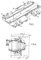
- Fig. 1 is a perspective view of the preferred tread belt link of the present invention;
- Fig. 2 is a second perspective view of the link of Fig. . 1, taken from below the link;
- Fig. 3 is a top plan view of the link of Fig. 1 which has been attached by connecting pins to two adjacent identical links;
- Fig. 4 is an enlarged cross-sectional view of a link taken along line 4-4 in Fig. 3;
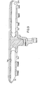
- Fig. 5 is a front-elevational view of the link shown in Fig. 1;
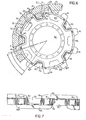
- Fig. 6 is a partial sectional view of the drive system showing a belt made up of links such as that shown in Fig. 3 engaged with the cooperating drive tumbler of the present invention, the tumbler being viewed from the side;
- Fig. 7 is a schematic top view of the tumbler wheel of Fig. 6;
- Fig. 8 is a schematic view, partly in section, showing the relationship of a tread belt made up of the preferred links and the cooperating drive tumbler, with arrows illustrating the various paths by which dirt can be expelled from the drive system; and
- Fig. 9 is a cross-sectional vied of a link taken along line 9-9 in Fig. 3 which is shown engaged with a tumbler pocket of the drive tumbler.
- Referring now to Figs. 1 and 3, there is shown a
tread belt link 10 which can be used in a drive system for mobile machinery. A number of such links may be joined together to form an endless ground engaging tread belt. Such belts can be disposed at the base on each side of a machine such as an excavator or a tractor to cause the machine to move. - The endless belt will normally pass under conventional rollers (not shown) that support the machine proper and the belt will then mesh with a cooperating drive tumbler wheel 40 (see Fig. 6) which is located at one end of the belt and then travel around to a conventional toothless idler tumbler (not shown) at the other end of the belt. This provides a drive system for propelling the machine along the ground.
- For purposes of clarity in the following description of the preferred embodiment, the direction of travel of the links in the drive system when the machine is moving forward will be called the forward direction and the direction of travel of the links when the machine is moving in reverse will be called the aft direction. Further, the direction across the link from one end to another will be referred to as the lateral direction.
- To further facilitate description, the direction through the link 10-from the drive wheel engaging top face 11 towards the bottom face 12 of the link will be referred to as radially outward, and the direction from the bottom face 12 of the link 10-towards the drive wheel engaging top face 11 will be referred to as radially inward.
- It can be seen that the
link 10 shown in Fig. 1 has a guidingcog 13 which rises upwardly from the central region of the top face 11. Thecog 13 may be formed with a flattenedtop 14 and sloping sides 16 and 17 which slope towards the forward and aft directions, respectively. Adjacent to the guidingcog 13, on each lateral side thereof, are rectangular shaped, flat bearing surfaces 18 and 19. It will be appreciated that the guidingcog 13 rises above these bearing surfaces, that bearingsurface 18 is extended forward beyond the forward terminus of thecog 13, and that bearingsurface 19 is extended aft beyond the aft terminus of thecog 13.' - The
link 10 is further provided with a firstset connecting ears 20 along the forward end of the link body, and a second set of connectingears 21 along the aft end of thelink 10. Theforward connecting ears 20 have a degree of symmetry with theaft connecting ears 21. If the link. were to be rotated 180 degrees around an axis extending through the center of the guidingcog 13 which is perpendicular to the plane of top face 11, the link would appear substantially identical to one viewing the link from a fixed position. -
Links 10 can be connected together as in Fig. 3 by inserting theforward connecting ears 20 of one link between theaft connecting ears 21 of the next link, thereby inter- digiting them together. Appropriate connectingpins 22 can be inserted in the alignedopenings 23 in the interdigited ears, and thepins 22 secured in place by suitable fastening means such as a T-bolt 24 and acotter pin 25. Four bolts, four connecting pins, and four cotter pins are used to complete the attachment of two additional links to a first link. - Continuing now with reference to Figs. 1, 2, and 4, on the forward 16 and aft 17 sides of the guiding
cog 13, located between the link bottom face 12 and link top face 11, there are drive surfaces 26. There are also forward andaft slots treads 29 separated by alongitudinal groove 30. - With particular reference to Fig. 3, it can be seen that when two or more links are placed together,
forward slot 27 of one link andaft slot 28 of the next link form a rectangular space oropening 31 between the two links. Theopening 31 between links is of sufficient size to receive a drive tooth 41 (Fig. 6) of thetumbler drive wheel 40, and also allow material to pass radially outward between the link top face 11 and link bottom face 12 when the links are attached together. - Turning now to Figs. 4 and 5, the guiding
cog 13 is shown as nearly trapezoidal in cross section with the bottom portion 13A being slightly rounded. This construction allows the drive surfaces 26 to make smoother contact withtumbler teeth 41. It will further be appreciated from Fig. 5 that in the preferred embodiment the top 14 of thecog 13 rises above the bearing surfaces 18 and 19 and that they are of a greater height than the remainder of the link (see adjacent surfaces 32). - In Fig. 6, there is shown a belt of
links 10 mounted on atumbler wheel 40. Thedrive wheel 40 has a plurality of circumferentially spacedteeth 41. There are ten of such teeth regularly spaced around the periphery of thedrive wheel 40. Between theteeth 41, there are a first set of fivepockets 42 that open radially outward and laterally towards the viewer. There is also a second set of fivepockets 43 which alternate with the first set around the wheel and that open radially outward and open laterally from the tumbler wheel away from the viewer. - As shown most clearly in Fig. 7, adjacent to the aligned
teeth 41 andalternate pockets wheel 40, and being formed such that theteeth 41 extend radially outward beyond thesegmented rims tooth 41 is extending beyond segmentedrim 44. Further to detail the structure of the tumbler wheel,teeth 41 are formed near thetermini 46 ofsegmented rims pockets - It will also be appreciated that
tooth 41 at point A is driving the belt at or near the centers ofpins 22 between connecting links. Thetooth 41 reaches this point by projecting into; theradial opening 31 formed byslots tooth 41 drives against a drivingsurface 26 on thecog 13, thereby propelling the link belt. As driving occurs at or near the pin centers, the noise of the device is reduced and the likelihood of excessive torque forces causing damage is reduced. - When assembled together, the alternating
segmented rims rims pockets - As shown in Fig. 6, the system is constructed such that the pitch angle of the links is less than the pitch angle of . the tumbler teeth. Not all of the
teeth 41 of thetumbler 40 which are contacting the links will perform a driving function at the same time. For example, while atooth 41 may be driving acog 13 at point A, at point F another tooth will not have yet reached the point of driving because of the difference in the pitch angles. This construction has the advantages previously discussed. - The working of the system can further be appreciated from Figs. 8 and 9. As shown in these views, the system of the invention allows dirt and stone removal in at least three directions. First, dirt and stones can be removed through the
radial opening 31 formed byslots cog 13 into the alternatingpockets cog 13 and then laterally outward. The combination of these possibilities provides for an improved self-cleaning capability. - Because of the shape of the
link 10 and its symmetry, it is highly suitable for casting. Various casting holes and cutouts such asopenings - The link can be formed of conventional casting metals. To improve the wear resistance of the conventional metals, the bearing surfaces 18 and 19 can be heat treated. In sum, then, the novel tread belt link and cooperating drive tumbler improve upon the performance of the prior art drive systems in dealing with the problems described above.
Claims (9)
1. A tread belt drive characterised by the combination of: a tubler wheel (40) having a segmented rim (44, 45), the rim having its segments alternately offset laterally from one another to form two rows of rim segments in which the segments of each row are circumferentially spaced from one another, a plurality of driving teeth (41) positioned between the rows, the teeth projecting radially outwardly therefrom and being in locations alongside the termini of said rim segments, and pockets (42, 43) located between said driving teeth that open both radially outward and laterally from the tumbler wheel; a plurality of links (10) connected to one another to form a tread belt and engageable with said tumbler wheel, the links having a link body that has a ground engaging bottom (12) and an upper face (11), a guiding cog (13) projecting upwardly from the central region of said top face that is receivable within a pocket of said tumbler wheel; a bearing surface (18, 19) on each side of said guiding cog that rides upon a rim segment of said tumbler wheel, a driven surface (26) at each side of the cog that is located between the link bottom and the link top face and in vertical alignment with the cog to be engaged by the tumbler teeth, and connecting ears (20, 21) along the sides of the link body that interdigit with lugs of adjacent links for connection therewith, said connecting ears having connection openings (23) with centers located beneath said bearing surfaces; and said links when connected together forming openings (31) between the bearing surfaces of adjacent links which are open at the link bottoms and which receive said tumbler driving teeth.
2. A tread belt drive characterised by the combination of: a tumbler wheel (40) having a plurality of circumferentially arranged pockets (42, 43) spaced from one another, each pocket being open both at its radially outward periphery and in a lateral direction, a plurality of teeth (41) located between said pockets and extending radially outward therefrom, and a segmented rim (44, 45) with spaced portions alongside said pockets and teeth; and a plurality of tread belt links (10) in meshing engagement with said tumbler wheel, each link having a ground engaging bottom (12) and an upper surface (11) spaced above said bottom, a centrally located cog (13) projecting above said upper surface and receivable in a tumbler wheel pocket, a tooth'engaging surface (26) at each side of the link that extends downwardly from said cog and lies between said ground engaging bottom and said upper surface, and connecting means (20, 21) along each side of the link for joining with adjacent links, connected links forming an opening (31) between facing tooth engaging surfaces of adjacent links, the opening being suitable to receive a tumbler tooth which is engagable with said tooth engaging surface (26) at a level lying between said ground engaging bottom and said upper surface, and also beneath the portion of said cog projecting above said upper surface, and said upper surface having a portion (18, 19) bearing upon said tumbler wheel rim.
3. A tread belt link (10) of the type which is formed with a ground engaging bottom (12), a drive wheel engaging top face (11) and connecting ears (20, 21) along its forward and aft sides which are suitable to interdigit with the ears of other links, characterised by a guiding cog (13) projecting upwardly from the central region of the top face (11), a bearing surface (18, 19) on each lateral side of the guiding cog, aligned drive surfaces (26) on the forward and aft sides (16, 17) of the guiding cog located between the link bottom (12) and link top (11) face, and a slot (27, 28) in alignment with the drive surfaces which is suitable to receive a drive tooth of the drive wheel and allow material to pass between the link top face and link bottom surface when two links are connected together.
4. A tread belt link according to claim 3, characterised in that one (18) of the bearing surfaces'extends forward of the forward drive surface (26) and the other (19) of the bearing surfaces extends aft of the aft drive surface.
5. A tread belt link according to claim 3 or 4, characterised in that the forward and aft connecting ears (20, 21) of the link are symmetrically formed 'along the sides of the link.
6. A tread belt link according to claim 3, 4 or 5, characterised in that the ground engaging bottom (12) is formed with traction rim means (29).
7. A tumbler wheel (40) for a tread belt drive, which wheel comprises a plurality of circumferentially spaced teeth (41) projecting radially outward from the wheel, characterised by two rows of segmented bearing rims (44, 45) alternately offset laterally from each other on the sides of the teeth, the segments of each row being circumferentially spaced and being formed such that the teeth extend radially beyond the segments, and a plurality of pockets (42, 43) located between the teeth, the pockets opening radially outward, and opening laterally from the wheel between the rim segments.
8. A tumbler wheel according to claim 7, characterised in that the teeth (41) are located adjacent the termini of the rim segments (44, 45).
9. A tumbler wheel according to claim 7 or 8, characterised in that the pockets (42, 43) are circumferentially and regularly spaced around the periphery of the wheel.
Applications Claiming Priority (2)
| Application Number | Priority Date | Filing Date | Title |
|---|---|---|---|
| US233856 | 1981-02-12 | ||
| US06/233,856 US4425007A (en) | 1981-02-12 | 1981-02-12 | Tread belt link and cooperating drive tumbler |
Publications (2)
| Publication Number | Publication Date |
|---|---|
| EP0058520A2 true EP0058520A2 (en) | 1982-08-25 |
| EP0058520A3 EP0058520A3 (en) | 1983-10-26 |
Family
ID=22878959
Family Applications (1)
| Application Number | Title | Priority Date | Filing Date |
|---|---|---|---|
| EP82300680A Withdrawn EP0058520A3 (en) | 1981-02-12 | 1982-02-11 | Tread belt link and cooperating drive tumbler |
Country Status (3)
| Country | Link |
|---|---|
| US (1) | US4425007A (en) |
| EP (1) | EP0058520A3 (en) |
| JP (1) | JPS57151476A (en) |
Cited By (3)
| Publication number | Priority date | Publication date | Assignee | Title |
|---|---|---|---|---|
| WO1992020564A1 (en) * | 1991-05-22 | 1992-11-26 | Drago Deutschland Gmbh | Caterpillar track link for a tracked vehicle |
| WO2008143755A1 (en) * | 2007-05-18 | 2008-11-27 | Caterpillar Inc. | Machine, track system and machine track segment |
| WO2017039998A1 (en) * | 2015-08-28 | 2017-03-09 | Caterpillar Inc. | Undercarriage assembly and track links for assembly |
Families Citing this family (19)
| Publication number | Priority date | Publication date | Assignee | Title |
|---|---|---|---|---|
| CA1215735A (en) * | 1984-08-29 | 1986-12-23 | Ontario Drive And Gear Limited | Tire-located track |
| US5409306A (en) * | 1993-11-29 | 1995-04-25 | Caterpillar Inc. | Track assembly |
| US6139121A (en) * | 1995-05-10 | 2000-10-31 | Bridgestone/Firestone, Inc. | Positive drive rubber track |
| US6076901A (en) * | 1997-11-05 | 2000-06-20 | Rankin; Mark T. | Track shoe for an endless track vehicle |
| AU738926B2 (en) * | 1998-03-12 | 2001-09-27 | Bradken Resources Pty Limited | A track shoe |
| DE19920025C2 (en) * | 1999-04-27 | 2001-03-08 | Mannesmann Ag | Crawler track |
| DE10019595C2 (en) * | 2000-04-20 | 2003-02-06 | Giesecke & Devrient Gmbh | Toothed belt wheel with board |
| KR100396213B1 (en) * | 2001-07-09 | 2003-08-27 | 이충철 | Track-shoe of amphibious caterpillar vehicles for leisure |
| US20080190462A1 (en) * | 2007-02-08 | 2008-08-14 | Habasit Ag | Sprocket For Easy Cleaning |
| US8776989B2 (en) * | 2007-02-08 | 2014-07-15 | Habasit Ag | Modular belt sprocket for easy cleaning |
| JPWO2014027530A1 (en) * | 2012-08-14 | 2016-07-25 | 日立建機株式会社 | Track |
| JPWO2014027531A1 (en) * | 2012-08-14 | 2016-07-25 | 日立建機株式会社 | Track |
| AU2014202781B2 (en) | 2013-05-24 | 2017-07-20 | Joy Global Surface Mining Inc | Crawler track |
| CA2871244C (en) | 2013-11-12 | 2023-05-09 | Harnischfeger Technologies, Inc. | Guide rail for crawler track |
| JP5956480B2 (en) * | 2014-01-30 | 2016-07-27 | 日立建機株式会社 | Track |
| USD748153S1 (en) * | 2014-05-22 | 2016-01-26 | Harnischfeger Technologies, Inc. | Crawler track shoe |
| US9902442B2 (en) * | 2015-04-06 | 2018-02-27 | John P. Moyna | Track link |
| US11254377B2 (en) | 2019-07-10 | 2022-02-22 | Caterpillar Inc. | Winged sprocket segments with notches |
| US11912354B2 (en) * | 2020-10-30 | 2024-02-27 | Caterpillar Inc. | Reduced material hydraulic mining shovel track pad |
Citations (8)
| Publication number | Priority date | Publication date | Assignee | Title |
|---|---|---|---|---|
| US1450471A (en) * | 1920-05-26 | 1923-04-03 | Holt Mfg Co | Tractor tread link |
| US1922357A (en) * | 1932-06-16 | 1933-08-15 | Marion Steam Shovel Co | Tumbler for crawling traction mechanism |
| US2302658A (en) * | 1939-01-14 | 1942-11-24 | Joseph W Artz | Crawler tractor driving means |
| US2530379A (en) * | 1947-04-05 | 1950-11-21 | Bucyrus Erie Co | Tread-belt link and cooperating driving tumbler |
| US3680928A (en) * | 1970-05-08 | 1972-08-01 | Bucyrus Erie Co | Tread belt drive |
| DE2160398B2 (en) * | 1971-12-06 | 1976-07-08 | Rheinstahl Schmiedetechnik Gmbh, 4640 Wattenscheid | Chain wheel for tracked vehicle chains - has spacing greater than chain pitch and chain plates supported on treads |
| US4176887A (en) * | 1977-05-06 | 1979-12-04 | O&K Orenstein & Koppel Aktiengesellschaft | Endless track traveling mechanism |
| US4278301A (en) * | 1977-12-23 | 1981-07-14 | Bucyrus-Erie Company | Tread belt and drive having involute gear drive |
-
1981
- 1981-02-12 US US06/233,856 patent/US4425007A/en not_active Expired - Fee Related
-
1982
- 1982-02-10 JP JP57019014A patent/JPS57151476A/en active Pending
- 1982-02-11 EP EP82300680A patent/EP0058520A3/en not_active Withdrawn
Patent Citations (8)
| Publication number | Priority date | Publication date | Assignee | Title |
|---|---|---|---|---|
| US1450471A (en) * | 1920-05-26 | 1923-04-03 | Holt Mfg Co | Tractor tread link |
| US1922357A (en) * | 1932-06-16 | 1933-08-15 | Marion Steam Shovel Co | Tumbler for crawling traction mechanism |
| US2302658A (en) * | 1939-01-14 | 1942-11-24 | Joseph W Artz | Crawler tractor driving means |
| US2530379A (en) * | 1947-04-05 | 1950-11-21 | Bucyrus Erie Co | Tread-belt link and cooperating driving tumbler |
| US3680928A (en) * | 1970-05-08 | 1972-08-01 | Bucyrus Erie Co | Tread belt drive |
| DE2160398B2 (en) * | 1971-12-06 | 1976-07-08 | Rheinstahl Schmiedetechnik Gmbh, 4640 Wattenscheid | Chain wheel for tracked vehicle chains - has spacing greater than chain pitch and chain plates supported on treads |
| US4176887A (en) * | 1977-05-06 | 1979-12-04 | O&K Orenstein & Koppel Aktiengesellschaft | Endless track traveling mechanism |
| US4278301A (en) * | 1977-12-23 | 1981-07-14 | Bucyrus-Erie Company | Tread belt and drive having involute gear drive |
Cited By (4)
| Publication number | Priority date | Publication date | Assignee | Title |
|---|---|---|---|---|
| WO1992020564A1 (en) * | 1991-05-22 | 1992-11-26 | Drago Deutschland Gmbh | Caterpillar track link for a tracked vehicle |
| WO2008143755A1 (en) * | 2007-05-18 | 2008-11-27 | Caterpillar Inc. | Machine, track system and machine track segment |
| WO2017039998A1 (en) * | 2015-08-28 | 2017-03-09 | Caterpillar Inc. | Undercarriage assembly and track links for assembly |
| US9688325B2 (en) | 2015-08-28 | 2017-06-27 | Caterpillar Inc. | Undercarriage assembly and track links for assembly |
Also Published As
| Publication number | Publication date |
|---|---|
| EP0058520A3 (en) | 1983-10-26 |
| US4425007A (en) | 1984-01-10 |
| JPS57151476A (en) | 1982-09-18 |
Similar Documents
| Publication | Publication Date | Title |
|---|---|---|
| US4425007A (en) | Tread belt link and cooperating drive tumbler | |
| EP0497597B1 (en) | Core bar for rubber track and rubber track travelling device | |
| US5154490A (en) | Ground engaging surface for endless tracks and wheels | |
| EP0893334B1 (en) | Rubber crawler | |
| US2854294A (en) | Crawler tumbler and track shoe | |
| US5380076A (en) | Rubber crawler belt of a tracked vehicle | |
| US20050035655A1 (en) | Track with offset drive lugs and drive wheel therefore | |
| US7823990B2 (en) | Sprocketed idler assembly | |
| US20020024256A1 (en) | Rubber crawler belt | |
| US5813733A (en) | Metal core member for rubber crawler belt, the rubber crawler belt and method of winding the same | |
| EP0495122B1 (en) | Core metal for rubber crawler and crawler device | |
| US4278301A (en) | Tread belt and drive having involute gear drive | |
| WO2020211761A1 (en) | Track system capable of moving heavy engineering machinery and engineering vehicle | |
| EP0515683A1 (en) | Rubber track for crawler vehicle | |
| JP3483787B2 (en) | Elastic crawler | |
| JP2002037152A (en) | Driving tumbler | |
| US4856853A (en) | Endless belt-type drive mechanism | |
| CN209757306U (en) | Engineering machinery crawler and engineering vehicle | |
| EP0006250B1 (en) | Toothing for a drive sprocket | |
| JPH08244657A (en) | Inner circumference drive type rubber crawler and sprocket | |
| EP0493875A1 (en) | Rubber track | |
| US20080157588A1 (en) | Track shoe having integral, trapezoid-shaped teeth | |
| JP3010109B2 (en) | Elastic crawler | |
| JPH0829725B2 (en) | Rubber track | |
| JP2871192B2 (en) | Crawler core metal and elastic crawler |
Legal Events
| Date | Code | Title | Description |
|---|---|---|---|
| PUAI | Public reference made under article 153(3) epc to a published international application that has entered the european phase |
Free format text: ORIGINAL CODE: 0009012 |
|
| AK | Designated contracting states |
Designated state(s): DE FR GB |
|
| PUAL | Search report despatched |
Free format text: ORIGINAL CODE: 0009013 |
|
| AK | Designated contracting states |
Designated state(s): DE FR GB |
|
| STAA | Information on the status of an ep patent application or granted ep patent |
Free format text: STATUS: THE APPLICATION IS DEEMED TO BE WITHDRAWN |
|
| 18D | Application deemed to be withdrawn |
Effective date: 19840626 |
|
| RIN1 | Information on inventor provided before grant (corrected) |
Inventor name: SOETEBER, RONALD J. |