EP0061995A1 - Sausage meat proportioning device - Google Patents
Sausage meat proportioning device Download PDFInfo
- Publication number
- EP0061995A1 EP0061995A1 EP82810105A EP82810105A EP0061995A1 EP 0061995 A1 EP0061995 A1 EP 0061995A1 EP 82810105 A EP82810105 A EP 82810105A EP 82810105 A EP82810105 A EP 82810105A EP 0061995 A1 EP0061995 A1 EP 0061995A1
- Authority
- EP
- European Patent Office
- Prior art keywords
- closure member
- rotor
- measuring device
- portioning
- sausage
- Prior art date
- Legal status (The legal status is an assumption and is not a legal conclusion. Google has not performed a legal analysis and makes no representation as to the accuracy of the status listed.)
- Ceased
Links
Images

Classifications
-
- A—HUMAN NECESSITIES
- A22—BUTCHERING; MEAT TREATMENT; PROCESSING POULTRY OR FISH
- A22C—PROCESSING MEAT, POULTRY, OR FISH
- A22C11/00—Sausage making ; Apparatus for handling or conveying sausage products during manufacture
- A22C11/02—Sausage filling or stuffing machines
- A22C11/0245—Controlling devices
Definitions
- the invention relates to a portioning device for a sausage mass according to the preamble of claim 1.
- a continuously working sausage filling device in which the sausage mass by means of a conveyor from a pre council container, e.g. B. a hopper, is transported into the filler neck for the sausages.
- the conveying device which is driven by an electric motor, has a rotor with radial slots, into which slides are inevitably guided such that their ends are constantly in contact with the inner wall of the rotor housing.
- the conveyor generates the pressure for the sausage meat transport, the angle of rotation between two positions being a measure of the portion ejected.
- the angle of rotation of the rotor is regulated electronically or mechanically for portioning.
- Another known portioning system which is manufactured and sold by the applicant, is equipped with a sausage meat piston which pressurizes the sausage meat mass and feeds via a channel to a portioning double piston which is arranged in a rotatable sleeve and which is arranged transversely to the channel.
- the portioning double piston has two functions: it serves both to measure the meat volume and to eject it. The strokes of the piston are accomplished by the inflowing meat mass under pressure.
- the portions can also be ejected mechanically or hydraulically. In these portioning systems with sausage meat, the portioning range is restricted because it depends on the stroke length and the col The diameter of the sausage meat is dependent. The systems are relatively accurate, but the handling is outdated.
- a sausage meat piston is also provided for generating the sausage meat delivery pressure.
- the meat is portioned with the meat flask itself, the stroke of which is electronically monitored.
- a pusher can be installed in front of the discharge pipe to interrupt the sausage meat stream.
- this system is inaccurate because the sausage mass contains gas and is therefore compressible.
- the piston movement is not proportional to the mass expelled, especially not for large sausage meat volumes and small portions.
- the object of the invention is to avoid the disadvantages of the known portioning devices mentioned above. According to the invention, this is done by the features listed in the characterizing part of claim 1.
- the invention provides a clear division achieved according to the functions of the individual elements, namely pressure generation, volumetric measurement, periodic interruption of the mass flow.
- the portioning device shown in Figures 1 and 2 has a roasting cylinder 1, in which a roasting piston 2 is arranged, which is connected via a piston rod 3 in a manner not shown with a drive member, for. B. a hydraulic drive is connected.
- the piston 2 generates a pressure p 1 in the sausage mass 4, which causes the sausage mass to be conveyed through the channel 5 into the filling tube 6, from where it enters the sausage casing.
- a measuring device 8 is arranged, which has a rotor 9, which is accommodated in a cylindrical measuring chamber 10, which is aligned transversely to the feed channel 5 or to the meat strand.
- the measuring device is designed on the principle of a slide pump, such as. B. described in DE-PS 1.432.513. Radial slots 11 are recessed in the rotor 9, in which the four slides 12 are guided. The latter are inevitably controlled by a slide guide that they are always pressed outwards against the chamber wall.
- the slide element 13 serves to interrupt the mass flow periodically. It is connected via a rod 14 to a hydraulic piston 15 in a hydraulic cylinder 16.
- This first piston / cylinder unit 17 serves to regulate the stroke of the slide element 13.
- Another hydraulic piston / cylinder unit 18 is articulated 19 to a housing part 20, and its piston rod 21 acts on a crank drive 38, which serves to rotate the rod 14 or the slide element 13 by 90 °, whereby the through bore 22 of the the latter no longer aligns with the sausage meat channel 5 and the mass flow is interrupted.
- the rotor 9 in turn is driven by the sausage meat stream and rotates synchronously with it.
- the drive power and the friction cause a small pressure difference ⁇ p between the meat pressure p 1 in the meat cylinder and the meat pressure p 2 in the filling tube 6.
- a number of projections 25 are evenly distributed over the circumference of the pulse generator disk 24, which trigger corresponding signals in the pulse meter 26 which are transmitted to the electronic control 27.
- the electronics 27 switches the hydraulic valve 28 of the second piston / cylinder unit 18, so that the slide element 13 is closed.
- the sausage strand is interrupted so that, for. B. a clip can be placed in the casing or a twisting of the casing can be done.
- the electronics are reset to "0" and the slide element 13 is opened so that the next portion of meat can be filled.
- the control is designed in such a way that when the main switch 29 is opened, the portion started is normally let through and then the slide element 13 is closed, as described above, but is no longer opened after the pause. After the pause, when the system is no longer started, the electronics 27 activate the switching valve 30, so that the hydraulic piston 15 moves into its other stop position and partially pulls the slide element 13 out of the slide guide 31. As a result, a pressure compensation space 32 is released in the slide guide 31.
- the sausage mass present in the filling tube 6 and under pressure p 2 is relaxed via the connecting line 33 and the space 32. This brewing retraction prevents sausage mass from flowing out of the filling tube 6 in the event of longer interruptions in operation.
- a continuously operating slide pump 34 is used instead of the sausage meat piston, which is fed by a filling funnel 35.
- the meat mass under pressure P1 4 can be fed via the common delivery line 36 to a plurality of portioning stations 37, each of which has a closure member and a measuring device.
- z. B. gear or screw pumps it would be possible to use other, known per se funding for generating the pressure for the mass flow, z. B. gear or screw pumps.
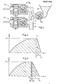
- the portion does not correspond to the selected number of pulses defined by the angle a in FIG. 1, but to an angle a + ⁇ N.
- the control diagram according to FIG. 4 where the ordinate is written with the angular velocity w and the abscissa represents the time axis t.
- the closing process S is initiated at time T 1 , at an angular velocity ⁇ 1 ' and is ended at time T 2 , the closing time t s being designated.
- a corresponds to the number of pulses or the flow rate during closing.
- the time ⁇ t is measured between the pulse 29 and the pulse 30.
- the angle ⁇ between the pulse 29 and the pulse 30 is given by the design of the encoder disc.
- the slide element 13 is now closed by means of a linear amplifier.
- the same closing path always results even at different pressures or outflow speeds or angular speeds of the sensor disc, or during the closing of the slide element 13, the same sausage meat volume always flows through the slide.
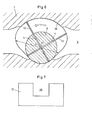
- two slides 12 are provided which cross one another.
- the slides which each have a recess 38, engage in one another.
- the inner wall 39 of the rotor chamber is designed so that the diameter D passing through the rotor axis 23 remains constant at all angular positions of the rotor.
- This embodiment of the rotor can be manufactured inexpensively in terms of production technology.
- the chamber wall only has to be accurate in the area shown in dash-dotted lines, i. H. have a close tolerance.
Abstract
Description
Die Erfindung betrifft eine Portioniereinrichtung für eine Wurstmasse gemäss dem Gattungsbegriff des Patentanspruches 1.The invention relates to a portioning device for a sausage mass according to the preamble of claim 1.
Aus der DE-PS 1.432.513 ist eine kontinuierlich arbeitende Wurstfülleinrichtung bekannt, bei welcher die Wurstmasse mittels einer Fördereinrichtung von einem Vorratsbehälter, z. B. einem Einfülltrichter, in den Abfüllstutzen für die Würste transportiert wird. Die durch einen Elektromotor angetriebene Fördereinrichtung weist einen Rotor mit radialen Schlitzen auf, in welchen Schieber zwangsläufig derart geführt sind, dass ihre Enden ständig an der Innenwand des Rotorgehäuses anliegen.From DE-PS 1.432.513 a continuously working sausage filling device is known, in which the sausage mass by means of a conveyor from a pre council container, e.g. B. a hopper, is transported into the filler neck for the sausages. The conveying device, which is driven by an electric motor, has a rotor with radial slots, into which slides are inevitably guided such that their ends are constantly in contact with the inner wall of the rotor housing.
Die Fördereinrichtung erzeugt den Druck für den Brättransport, wobei der Drehwinkel zwischen zwei Positionen ein Mass ist für die ausgestossene Portion. Zum Portionieren wird der Drehwinkel des Rotors elektronisch oder mechanisch geregelt.The conveyor generates the pressure for the sausage meat transport, the angle of rotation between two positions being a measure of the portion ejected. The angle of rotation of the rotor is regulated electronically or mechanically for portioning.
Andere kontinuierlich arbeitende Fülleinrichtungen weisen Zahnrad- oder Schneckenförderer (DE-AS 11 32 464) auf. Diese kontinuierlich arbeitenden Fülleinrichtungen sind aber mit verschiedenen Nachteilen behaftet. Das Fördersystem muss massiv sein, damit z. B. Rohwurst gefördert werden kann. Dabei müssen Drücke bis z. B. 20 bar erzeugt werden, was ein entsprechendes Antriebsmoment erfordert. Die massive Bauweise ist bezüglich der Beschleunigung ungünstig, was bei Stückzahlen von über 200 Portionen/Minute zur Auswirkung kommt. Neben der massiven Bauweise müssen die Fördersysteme gross dimensioniert sein, so dass die Portioniereinrichtung als Ganzes sehr voluminös ist. Schliesslich kann bei dünnflüssiger Wurstmasse "Schlupf"
auftreten; um dies zu verhindern, müssen in der Fabrikation sehr enge Toleranzen eingehalten werden, was eine Verteuerung mit sich bringt.Other continuously operating filling devices have gear or screw conveyors (DE-AS 11 32 464). However, these continuously operating filling devices have various disadvantages. The conveyor system must be massive so that e.g. B. raw sausage can be promoted. Pressures up to z. B. 20 bar are generated, which requires a corresponding drive torque. The massive design is unfavorable in terms of acceleration, which is the case with quantities of over 200 portions / minute comes into effect. In addition to the solid construction, the conveyor systems must be large, so that the portioning device as a whole is very voluminous. Finally, "slippage"
occur; In order to prevent this, very tight tolerances must be adhered to in production, which leads to an increase in price.
Ein weiteres bekanntes Portioniersystem, das von der Anmelderin hergestellt und vertrieben wird, ist mit einem Brätkolben ausgerüstet, der die Brätmasse unter Druck setzt und über einen Kanal einem in einer drehbaren Büchse angeordneten Portionier-Doppelkolben zuführt, welcher quer zum Kanal angeordnet ist. Der Portionier-Doppelkolben besitzt zwei Funktionen: Er dient sowohl zum Messen des Brätvolumens wie auch zum Ausstossen desselben. Die Hübe des Kolbens werden dabei durch die unter Druck stehende zufliessende Brätmasse bewerkstelligt. Bei anderen Kolbenfüller-Portioniersystemen kann das Ausstossen der Portionen auch mechanisch oder hydraulisch erfolgen. Bei diesen Portioniersystemen mit Brätkolben ist der Portionierbereich eingeschränkt, da er von der Hublänge und dem Kolbendurchmesser des Brätkolbens abhängig ist. Die Systeme sind zwar relativ genau, aber von der Handhabung her veraltet.Another known portioning system, which is manufactured and sold by the applicant, is equipped with a sausage meat piston which pressurizes the sausage meat mass and feeds via a channel to a portioning double piston which is arranged in a rotatable sleeve and which is arranged transversely to the channel. The portioning double piston has two functions: it serves both to measure the meat volume and to eject it. The strokes of the piston are accomplished by the inflowing meat mass under pressure. With other piston filler portioning systems, the portions can also be ejected mechanically or hydraulically. In these portioning systems with sausage meat, the portioning range is restricted because it depends on the stroke length and the col The diameter of the sausage meat is dependent. The systems are relatively accurate, but the handling is outdated.
Beim Kolbenfüller-Portioniersystem gemäss der EU-A1-13552 ist ebenfalls ein Brätkolben zur Erzeugung des Brätförderdruckes vorgesehen. Die Portionierung der Brätmasse erfolgt mit dem Brätkolben selbst, dessen Hub elektronisch überwacht wird. Vor dem Ausstossrohr kann noch ein Schieber eingebaut sein, um den Brätstrom zu unterbrechen. Dieses System ist aber ungenau, weil die Wurstmasse Gas enthält und somit kompressibel ist. Dadurch ist die Kolbenbewegung nicht proportional der ausgestossenen Masse, insbesondere nicht bei grossen Brätvolumen und kleinen Portionen.In the piston filler portioning system according to EU-A1-13552, a sausage meat piston is also provided for generating the sausage meat delivery pressure. The meat is portioned with the meat flask itself, the stroke of which is electronically monitored. A pusher can be installed in front of the discharge pipe to interrupt the sausage meat stream. However, this system is inaccurate because the sausage mass contains gas and is therefore compressible. As a result, the piston movement is not proportional to the mass expelled, especially not for large sausage meat volumes and small portions.
Aufgabe der Erfindung ist es, die Nachteile der vorstehend erwähnten, bekannten Portioniereinrichtungen zu vermeiden. Erfindungsgemäss erfolgt dies durch die im kennzeichnenden Teil des Anspruches 1 aufgeführten Merkmale.The object of the invention is to avoid the disadvantages of the known portioning devices mentioned above. According to the invention, this is done by the features listed in the characterizing part of claim 1.
Durch die Erfindung wird eine klare Unterteilung nach den Funktionen der einzelnen Elemente erzielt, und zwar Druckerzeugung, volumetrisches Messen, periodisches Unterbrechen des Massenstromes.The invention provides a clear division achieved according to the functions of the individual elements, namely pressure generation, volumetric measurement, periodic interruption of the mass flow.
Dies hat folgende wesentliche Vorteile:
- Der Druck für den Massenstrom kann durch irgendein druckerzeugendes Fördermittel, z. B. eine Schieberpumpe oder eine Kolbenvorrichtung, erhalten werden. Die volumetrische Messeinrichtung misst den effektiven Volumenstrom in der Nähe des Brätaustrittes. Da die Messeinrichtung, die zweckmässigerweise aus einem Rotor mit darin zwangsläufig radial geführten Schiebern besteht, nur das Moment für den Antrieb eines Impulsmessers für die elektronische Steuerung und zur Ueberwindung der Reibung liefern muss, ist nur ein kleiner Druckunterschied im Brätstrom notwendig. Aus diesem Grund kann der Antrieb des Rotors durch den Brätstrom selber erfolgen, und es müssen keine separaten Antriebe vorgesehen sein. Ferner sind minimale Schieber in Anzahl und Grösse notwendig. Da praktisch kein Schlupf entsteht, sind die konstruktiven und fabrikatorischen Anforderungen klein. In der Praxis hat es sich gezeigt, dass der Rotordurchmesser wesentlich kleiner ausgeführt werden kann im Vergleich zu bekannten, direkt angetriebenen Schieberpumpen. Die Grösse der Portionen ist an keine Bedingung geknüpft, da ein beliebig grosses Massenvolumen gemessen werden kann.
- The pressure for the mass flow can be determined by any pressure generating means, e.g. B. a slide pump or a piston device can be obtained. The volumetric measuring device measures the effective volume flow in the vicinity of the brewing outlet. Since the measuring device, which expediently consists of a rotor with inevitably radially guided sliders, only has to deliver the moment for driving a pulse meter for the electronic control and for overcoming the friction, only a small pressure difference in the sausage meat stream is necessary. For this reason, the drive of the rotor can be carried out by the meat stream itself, and no separate drives have to be provided. Furthermore, minimal number and size of sliders are necessary. Since there is practically no slippage, the design and manufacturing requirements are small. In practice, it has been shows that the rotor diameter can be made much smaller compared to known, directly driven vane pumps. The size of the portions is not tied to any condition, since any mass volume can be measured.
Nachfolgend werden anhand der Zeichnungen Ausführungsbeispiele der Erfindung näher erläutert. Es zeigen:
- Fig. 1 einen Querschnitt durch eine Portioniereinrichtung mit einem Kolben als druckerzeugendes Fördermittel,
- Fig. 2 einen Ausschnitt aus Fig. 1, wobei das Verschlussorgan in geschlossener Stellung gezeigt ist,
- Fig. 3 zwei Portionierstationen, bestehend je aus einer volumetrischen Messvorrichtung und einem Verschlussorgan, wobei die Portionierstationen von einer gemeinsamen Brätpumpe versorgt werden,
- Fig. 4 + 5 zwei Steuerungsdiagramme,
- Fig. 6 einen Querschnitt durch einen Rotor mit Schiebern,
- Fig. 7 eine Ansicht eines Schiebers.
- 1 shows a cross section through a portioning device with a piston as a pressure-generating conveying means,
- 2 shows a detail from FIG. 1, the closure member being shown in the closed position,
- 3 two portioning stations, each consisting of a volumetric measuring device and a closure member, the portioning stations being supplied by a common sausage meat pump,
- 4 + 5 two control diagrams,
- 6 shows a cross section through a rotor with slides,
- Fig. 7 is a view of a slide.
Die in den Figuren 1 und 2 dargestellte Portioniereinrichtung weist einen Brätzylinder 1 auf, in welchem ein Brätkolben 2 angeordnet ist, der über eine Kolbenstange 3 in nicht näher dargestellter Weise mit einem Antriebsorgan, z. B. einem Hydraulikantrieb, verbunden ist. Der Kolben 2 erzeugt in der Brätmasse 4 ein Druck pl, welcher bewirkt, dass die Brätmasse durch den Kanal 5 in das Füllrohr 6 gefördert wird, von wo es in die Wursthülle gelangt.The portioning device shown in Figures 1 and 2 has a roasting cylinder 1, in which a
Im Gehäuse 7 der Portioniereinrichtung ist eine Messvorrichtung 8 angeordnet, die einen Rotor 9 aufweist, welcher in einer zylindrischen Messkammer 10 untergebracht ist, die quer zum Zuführungskanal 5 bzw. zum Brätstrang ausgerichtet ist.In the
Die Messvorrichtung ist nach dem Prinzip einer Schieberpumpe ausgebildet, wie z. B. in der DE-PS 1.432.513 beschrieben. Im Rotor 9 sind radiale Schlitze 11 ausgespart, in denen die vier Schieber 12 geführt sind. Letztere werden durch eine Schieberführung zwangsläufig so gesteuert, dass sie stets nach aussen an die Kammerwandung gedrückt werden.The measuring device is designed on the principle of a slide pump, such as. B. described in DE-PS 1.432.513.
Im Anschluss an die Messvorrichtung 8 befindet sich im Gehäuse 7 ein zylindrisches Schieberlement 13, welches wiederum quer zum Brätkanal 5 angeordnet ist. Das Schieberelement 13 dient dazu, den Massenstrom periodisch zu unterbrechen. Es ist über eine Stange 14 mit einem Hydraulikkolben 15 in einem Hydraulikzylinder 16 verbunden. Diese erste Kolben/Zylindereinheit 17 dient dazu, den Hub des Schieberelementes 13 zu regulieren.Following the
Eine weitere hydraulische Kolben/Zylindereinheit 18 ist gelenkig 19 mit einem Gehäuseteil 20 verbunden, und ihre Kolbenstange 21 wirkt auf einen Kurbelantrieb 38 ein, der dazu dient, die Stange 14 bzw. das Schieberelement 13 um 90° zu verdrehen, wodurch die Durchlassbohrung 22 des letzteren nicht mehr mit dem Brätkanal 5 fluchtet und der Massenstrom unterbrochen wird.Another hydraulic piston /
Auf der Rotorachse 23 sitzt eine Impulsgeberscheibe 24, welche vom Rotor 9 angetrieben wird. Der Rotor 9 seinerseits wird vom Brätstrom angetrieben und dreht sich synchron mit diesem. Die Antriebsleistung und die Reibung verursachen eine kleine Druckdifferenz Δp zwischen dem Brätdruck p1 im Brätzylinder und dem Brätdruck p2 im Füllrohr 6.A
Ueber den Umfang der Impulsgeberscheibe 24 ist eine Anzahl Vorsprünge 25 gleichmässig verteilt, welche im Impulsmesser 26 entsprechende Signale auslösen, die an die elektronische Steuerung 27 übermittelt werden. Wenn die vorgewählte Impulszahl (die einem bestimmten Drehwinkel a des Rotors entspricht) erreicht wird, schaltet die Elektronik 27 das Hydraulikventil 28 der zweiten Kolben/ Zylindereinheit 18, so dass das Schieberelement 13 geschlossen wird. Der Wurststrang wird unterbrochen, damit z. B. bei der Darmhülle ein Clip gesetzt werden kann oder eine Abdrehung der Darmhülle erfolgen kann.A number of projections 25 are evenly distributed over the circumference of the
Nach der Pause wird die Elektronik wieder auf "0" gesetzt, und das Schieberelement 13 wird geöffnet, damit die nächste Brätportion abgefüllt werden kann.After the pause, the electronics are reset to "0" and the
Die Steuerung ist so ausgelegt, dass, wenn der Hauptschalter 29 geöffnet wird, zuerst die angefangene Portion normal durchgelassen wird und anschliessend das Schieberelement 13, wie vorgehend beschrieben, geschlossen, jedoch nach der Pause nicht mehr geöffnet wird. Nach der Pause, wenn nicht mehr gestartet wird, aktiviert die Elektronik 27 das Schaltventil 30, so dass der Hydraulikkolben 15 in seine andere Anschlagposition fährt und das Schieberelement 13 teilweise aus der Schieberführung 31 herauszieht. Dadurch wird in der Schieberführung 31 ein Druckausgleichraum 32 freigegeben.The control is designed in such a way that when the
Die im Füllrohr 6 vorhandene, unter dem Druck p2 stehende Wurstmasse wird über die Verbindungsleitung 33 und den Raum 32 entspannt. Durch diesen Brätrückzug wird verhindert, dass bei längeren Betriebsunterbrüchen Wurstmasse aus dem Füllrohr 6 ausfliesst.The sausage mass present in the filling
Beim Ausführungsbeispiel gemäss der Figur 3 wird anstelle des Brätkolbens eine kontinuierlich arbeitende Schieberpumpe 34 eingesetzt, die von einem Einfülltrichter 35 gespeist wird. Die unter dem Druck P1 stehende Brätmasse 4 kann über die gemeinsame Förderleitung 36 mehreren Portionierstationen 37 zugeführt werden, die je ein Abschlussorgan und eine Messvorrichtung aufweisen. Selbstverständlich wäre es möglich, zur Erzeugung des Druckes für den Massenstrom auch andere, an sich bekannte Fördermittel zu verwenden, z. B. Zahnrad- oder Schneckenpumpen.In the embodiment according to FIG. 3, a continuously operating slide pump 34 is used instead of the sausage meat piston, which is fed by a filling
Bei der Steuerung entspricht die Portion nicht der gewählten, durch den Winkel a in der Figur 1 definierten Impulszahl, sondern einem Winkel a + αN. Dies geht aus dem Steuerungsdiagramm gemäss Figur 4 hervor, wo die Ordinate mit der Winkelgeschwindigkeit w angeschrieben ist und die Abszisse die Zeitachse t darstellt.In the control, the portion does not correspond to the selected number of pulses defined by the angle a in FIG. 1, but to an angle a + α N. This can be seen from the control diagram according to FIG. 4, where the ordinate is written with the angular velocity w and the abscissa represents the time axis t.
Der Schliessvorgang S wird zum Zeitpunkt T1 eingeleitet, bei einer Winkelgeschwindigkeit ω1' und ist zum Zeitpunkt T2 beendet, wobei die Schliesszeit ts bezeichnet sei. a entspricht der Impulszahl bzw. der Durchflussmenge während des Schliessens. Bei gleichbleibendem, bekanntem Druckverhalten ist die Winkelgeschwindigkeit ωs während des Schliessvorganges als Funktion der Schliesszeit jeweils gleich, so dass bei gleicher Zeit ts aN konstant ist und entsprechend berücksichtigt werden kann, um eine gewünschte Portion bzw. Füllmenge zu erhalten.The closing process S is initiated at time T 1 , at an angular velocity ω 1 ' and is ended at time T 2 , the closing time t s being designated. a corresponds to the number of pulses or the flow rate during closing. With the known pressure behavior remaining the same, the angular velocity ω s during the closing process is always the same as a function of the closing time, so that at the same time t s aN is constant and can be taken into account accordingly in order to obtain a desired portion or filling quantity.
Bei Anwendungsfällen, wo der Nachlauf aN genau definiert sein muss, wird wie folgt vorgegangen (Diagramm gemäss Figur 5):
- Die Portion soll z. B. 40 Impulsen der Geberscheibe entsprechen bzw. dem Winkel a40. Der Nachlaufwinkel αN muss in a40 enthalten sein. Der Steuerrechner wird nun so programmiert, dass z. B. immer die letzten 10 Impulse während des Schliessens des Schieberelementes 13 erfolgen sollen, d. h. das Schliessen wird beim Impuls 30 eingeleitet.
- The portion is said to B. 40 pulses of the encoder disc correspond to the angle a 40 . The caster angle α N must be included in a 40 . The control computer is now programmed so that, for. B. always the last 10 pulses should take place during the closing of the
slide element 13, ie the closing is initiated atpulse 30.
Zwischen dem Impuls 29 und dem Impuls 30 wird die Zeit Δt gemessen. Der Winkel Δα zwischen dem Impuls 29 und dem Impuls 30 ist von der Konstruktion der Geberscheibe aus gegeben. Daraus kann die Winkelgeschwindigkeit ws berechnet werden, nämlich ws = Δα ÷ Δt.The time Δt is measured between the
Mit der Winkelgeschwindigkeit ωs und dem Schliesswinkel aN kann die Schliesszeit t berechnet werden:
- ts = 2αN ÷ ωs.
- t s = 2α N ÷ ωs.
Innerhalb der Zeit t wird nun das Schieberelement 13 mittels Linearverstärker geschlossen. So ergibt sich auch bei verschiedenen Drücken bzw. Ausfliessgeschwindigkeiten bzw. Winkelgeschwindigkeiten der Geberscheibe immer der gleiche Schliessweg bzw. während des Schliessens vom Schieberelement 13 fliesst immer das gleiche Brätvolumen durch den Schieber.Within the time t, the
Bei der Ausführungsform des Rotors 9 gemäss Figur 6 sind zwei Schieber 12 vorgesehen, die sich wechselweise kreuzen. Die Schieber, die je eine Aussparung 38 aufweisen, greifen dabei ineinander. Die Innenwandung 39 der Rotorkammer ist nach einer Kurve so gekrümmt ausgebildet, dass der durch die Rotorachse 23 gehende Durchmesser D konstant bleibt bei allen Drehwinkellagen des Rotors. Diese Ausführungsform des Rotors lässt sich fabrikationstechnisch preisgünstig herstellen. Die Kammerwandung muss nur im strichpunktiert eingezeichneten Bereich genau sein, d. h. eine enge Toleranz aufweisen.In the embodiment of the
Claims (10)
nach aussen an die Innenwandung der Rotorkammer (10) gedrückt sind.3. Device according to claim 1, characterized in that the measuring device (8) is designed according to the principle of a slide pump, wherein it has a rotor (9) with radial slots (11), in which a plurality of slides (12) are mounted, the are controlled by a guide so that their ends
are pressed outwards against the inner wall of the rotor chamber (10).
Applications Claiming Priority (2)
| Application Number | Priority Date | Filing Date | Title |
|---|---|---|---|
| CH206881 | 1981-03-26 | ||
| CH2068/81 | 1981-03-26 |
Publications (1)
| Publication Number | Publication Date |
|---|---|
| EP0061995A1 true EP0061995A1 (en) | 1982-10-06 |
Family
ID=4225144
Family Applications (1)
| Application Number | Title | Priority Date | Filing Date |
|---|---|---|---|
| EP82810105A Ceased EP0061995A1 (en) | 1981-03-26 | 1982-03-11 | Sausage meat proportioning device |
Country Status (2)
| Country | Link |
|---|---|
| EP (1) | EP0061995A1 (en) |
| ES (1) | ES510804A0 (en) |
Cited By (10)
| Publication number | Priority date | Publication date | Assignee | Title |
|---|---|---|---|---|
| FR2538104A1 (en) * | 1982-12-15 | 1984-06-22 | Nordischer Maschinenbau | Portioning device for pasty material |
| EP0143311A1 (en) * | 1983-10-28 | 1985-06-05 | VEMAG Maschinenbau GmbH | Proportioning device |
| DE3518529C1 (en) * | 1985-05-23 | 1986-05-07 | Nordischer Maschinenbau Rud. Baader GmbH + Co KG, 2400 Lübeck | Device for dispensing pasty fillings in portions |
| EP0245891A1 (en) * | 1986-05-12 | 1987-11-19 | RISCO BREVETTI S.p.A. | Bagging and apportioning machine for sausages and various bagged products |
| EP0439671A1 (en) * | 1990-01-31 | 1991-08-07 | Albert Handtmann Maschinenfabrik GmbH & Co. KG | Method and device for stuffing sausages by dividing a string of sausages |
| WO1998022206A2 (en) * | 1996-11-21 | 1998-05-28 | Vemag Maschinen- Und Anlagenbau Gmbh | Multi-outlet depositor |
| NL1004765C2 (en) * | 1996-12-13 | 1998-06-17 | Stork Protecon Langen Bv | Device for portioning food. |
| EP0898893A1 (en) * | 1997-08-29 | 1999-03-03 | Heinrich Frey Maschinenbau GmbH | Device for stuffing sausage meat |
| CN102524346A (en) * | 2010-12-01 | 2012-07-04 | 复合夹具系统两合公司 | Clipping machine and method for controlling said clipping machine |
| EP2713757B1 (en) | 2011-05-24 | 2015-07-08 | Marel Townsend Further Processing B.V. | Moulding device and method for moulding a food product |
Families Citing this family (1)
| Publication number | Priority date | Publication date | Assignee | Title |
|---|---|---|---|---|
| ES2053378B1 (en) * | 1992-03-02 | 1998-04-01 | Ind Fuerpla S L | STUFFING MACHINE FOR MEAT PRODUCTS WITH CONTINUOUS DOSAGE. |
Citations (7)
| Publication number | Priority date | Publication date | Assignee | Title |
|---|---|---|---|---|
| DE54866C (en) * | G. BÄUER-LEIN-GERMANN in Zürich-Unterstrafs, Beckenhofstrafse 37 | Sausage filling machine | ||
| US3207368A (en) * | 1963-12-02 | 1965-09-21 | Mayer & Co Inc O | Product metering apparatus |
| DE1432504A1 (en) * | 1965-04-29 | 1969-03-13 | Heinrich Frey | Hydraulically operated filling and dividing machine |
| DE2249070A1 (en) * | 1970-05-26 | 1974-04-18 | Karl Schnell | Sausage filling machine - with feed pump control switch operated by output side guide rollers |
| EP0013552A1 (en) * | 1979-01-09 | 1980-07-23 | ALBERT HANDTMANN GMBH & CO. | Method and apparatus for portioning a pasty mass, particularly sausage stock |
| EP0019711A1 (en) * | 1979-05-26 | 1980-12-10 | VEMAG Verdener Maschinen- und Apparatebau GmbH | Device for intermittently thrusting out sausage stock or the like |
| WO1981003259A1 (en) * | 1980-05-16 | 1981-11-26 | Handtmann Gmbh & Co A | Apparatus for dividing a mass into successive portions,particularly sausage meat |
-
1982
- 1982-03-11 EP EP82810105A patent/EP0061995A1/en not_active Ceased
- 1982-03-25 ES ES510804A patent/ES510804A0/en active Granted
Patent Citations (7)
| Publication number | Priority date | Publication date | Assignee | Title |
|---|---|---|---|---|
| DE54866C (en) * | G. BÄUER-LEIN-GERMANN in Zürich-Unterstrafs, Beckenhofstrafse 37 | Sausage filling machine | ||
| US3207368A (en) * | 1963-12-02 | 1965-09-21 | Mayer & Co Inc O | Product metering apparatus |
| DE1432504A1 (en) * | 1965-04-29 | 1969-03-13 | Heinrich Frey | Hydraulically operated filling and dividing machine |
| DE2249070A1 (en) * | 1970-05-26 | 1974-04-18 | Karl Schnell | Sausage filling machine - with feed pump control switch operated by output side guide rollers |
| EP0013552A1 (en) * | 1979-01-09 | 1980-07-23 | ALBERT HANDTMANN GMBH & CO. | Method and apparatus for portioning a pasty mass, particularly sausage stock |
| EP0019711A1 (en) * | 1979-05-26 | 1980-12-10 | VEMAG Verdener Maschinen- und Apparatebau GmbH | Device for intermittently thrusting out sausage stock or the like |
| WO1981003259A1 (en) * | 1980-05-16 | 1981-11-26 | Handtmann Gmbh & Co A | Apparatus for dividing a mass into successive portions,particularly sausage meat |
Cited By (18)
| Publication number | Priority date | Publication date | Assignee | Title |
|---|---|---|---|---|
| FR2538104A1 (en) * | 1982-12-15 | 1984-06-22 | Nordischer Maschinenbau | Portioning device for pasty material |
| EP0143311A1 (en) * | 1983-10-28 | 1985-06-05 | VEMAG Maschinenbau GmbH | Proportioning device |
| DE3518529C1 (en) * | 1985-05-23 | 1986-05-07 | Nordischer Maschinenbau Rud. Baader GmbH + Co KG, 2400 Lübeck | Device for dispensing pasty fillings in portions |
| EP0204086A1 (en) * | 1985-05-23 | 1986-12-10 | Nordischer Maschinenbau Rud. Baader Gmbh + Co Kg | Device for the delivery of flowable products in portions |
| US4712273A (en) * | 1985-05-23 | 1987-12-15 | Wolfgang Wagner | Device for delivering a pasty stuffing material in portions |
| EP0245891A1 (en) * | 1986-05-12 | 1987-11-19 | RISCO BREVETTI S.p.A. | Bagging and apportioning machine for sausages and various bagged products |
| EP0439671A1 (en) * | 1990-01-31 | 1991-08-07 | Albert Handtmann Maschinenfabrik GmbH & Co. KG | Method and device for stuffing sausages by dividing a string of sausages |
| US5083970A (en) * | 1990-01-31 | 1992-01-28 | Albert Handtmann Maschinenfabrick Gmbh & Co. Kg | Method and a filling machine for producing sausages by dividing a sausage string |
| WO1998022206A2 (en) * | 1996-11-21 | 1998-05-28 | Vemag Maschinen- Und Anlagenbau Gmbh | Multi-outlet depositor |
| WO1998022206A3 (en) * | 1996-11-21 | 1998-07-09 | Vemag Maschinen & Anlagenbau Gmbh | Multi-outlet depositor |
| US5906297A (en) * | 1996-11-21 | 1999-05-25 | Cole; Russell H. | Multi-outlet depositor |
| NL1004765C2 (en) * | 1996-12-13 | 1998-06-17 | Stork Protecon Langen Bv | Device for portioning food. |
| EP0847695A1 (en) * | 1996-12-13 | 1998-06-17 | Stork Protecon-Langen B.V. | Apparatus for portioning food |
| EP0898893A1 (en) * | 1997-08-29 | 1999-03-03 | Heinrich Frey Maschinenbau GmbH | Device for stuffing sausage meat |
| CN102524346A (en) * | 2010-12-01 | 2012-07-04 | 复合夹具系统两合公司 | Clipping machine and method for controlling said clipping machine |
| CN102524346B (en) * | 2010-12-01 | 2015-10-07 | 复合夹具系统两合公司 | Fore shaft machine and control method thereof |
| EP2713757B1 (en) | 2011-05-24 | 2015-07-08 | Marel Townsend Further Processing B.V. | Moulding device and method for moulding a food product |
| US9526269B2 (en) | 2011-05-24 | 2016-12-27 | Marel Townsend Further Procesing B.V. | Moulding device and method for moulding a food product |
Also Published As
| Publication number | Publication date |
|---|---|
| ES8303034A1 (en) | 1983-02-01 |
| ES510804A0 (en) | 1983-02-01 |
Similar Documents
| Publication | Publication Date | Title |
|---|---|---|
| EP0409001B1 (en) | Liquid injection device | |
| DD241189A5 (en) | METHOD FOR INJECTING VISCOUS LIQUID IN BREAD OR CONFECTIONERY | |
| DE3241985A1 (en) | DISPLAY DEVICE FOR A PUMP FOR INTRAVENOUSLY PUTING IN LIQUIDS | |
| DE2641359A1 (en) | DEVICE FOR THE DOSED ADDITION OF ADDITIVES INTO STREAMING LIQUIDS | |
| EP0061995A1 (en) | Sausage meat proportioning device | |
| EP0051626B1 (en) | Apparatus for dividing a mass into successive portions, parcicularly sausage meat | |
| DE3303655A1 (en) | DEVICE FOR VOLUMETRIC DISPENSING OF SCHUETTGUT | |
| DE3341658A1 (en) | METHOD AND DEVICE FOR LUBRICATING A CHAIN | |
| DE3247035C2 (en) | ||
| DE1916056C3 (en) | Dosler pump | |
| DE2741803C2 (en) | Device for conveying and / or dosing liquid to highly viscous media | |
| EP0845215B1 (en) | Apparatus for injecting liquid into pieces of food | |
| DE2840029A1 (en) | Dispenser for liquids, pastes, flour, sand, roots - has stepping and auxiliary motor driven feeders controlled by detector | |
| DE3518529C1 (en) | Device for dispensing pasty fillings in portions | |
| DE2155245C3 (en) | Device for filling pressurized sausage mass od.dgi | |
| EP0143311A1 (en) | Proportioning device | |
| EP0628390B1 (en) | Proportioning and conveyer pump and employment of such a pump for making moulded resin bodies | |
| EP0159681A2 (en) | Multicomponent proportioning apparatus | |
| EP0123781B2 (en) | Device for influencing the rotation speed of a shaft | |
| EP1884466B1 (en) | Filling facility for flowable masses | |
| DE3339274A1 (en) | Metering device | |
| DE2121006A1 (en) | Method and device for portioning, filling and twisting off a pasty mass in a tubular casing | |
| DE4344922C2 (en) | Device for filling one or more casting molds with pourable liquid media | |
| DE3422521A1 (en) | DEVICE FOR VOLUMETRIC DELIVERY OF SCHUETTGUT | |
| DE3305643C2 (en) |
Legal Events
| Date | Code | Title | Description |
|---|---|---|---|
| PUAI | Public reference made under article 153(3) epc to a published international application that has entered the european phase |
Free format text: ORIGINAL CODE: 0009012 |
|
| AK | Designated contracting states |
Designated state(s): AT BE CH DE FR GB IT LU NL SE |
|
| 17P | Request for examination filed |
Effective date: 19830328 |
|
| STAA | Information on the status of an ep patent application or granted ep patent |
Free format text: STATUS: THE APPLICATION HAS BEEN REFUSED |
|
| 18R | Application refused |
Effective date: 19841207 |
|
| RIN1 | Information on inventor provided before grant (corrected) |
Inventor name: GEISSBUEHLER, HANS |