EP0062913A1 - Drip chamber - Google Patents
Drip chamber Download PDFInfo
- Publication number
- EP0062913A1 EP0062913A1 EP82103060A EP82103060A EP0062913A1 EP 0062913 A1 EP0062913 A1 EP 0062913A1 EP 82103060 A EP82103060 A EP 82103060A EP 82103060 A EP82103060 A EP 82103060A EP 0062913 A1 EP0062913 A1 EP 0062913A1
- Authority
- EP
- European Patent Office
- Prior art keywords
- drip chamber
- nipple
- membrane
- chamber according
- opening
- Prior art date
- Legal status (The legal status is an assumption and is not a legal conclusion. Google has not performed a legal analysis and makes no representation as to the accuracy of the status listed.)
- Granted
Links
Images

Classifications
-
- A—HUMAN NECESSITIES
- A61—MEDICAL OR VETERINARY SCIENCE; HYGIENE
- A61M—DEVICES FOR INTRODUCING MEDIA INTO, OR ONTO, THE BODY; DEVICES FOR TRANSDUCING BODY MEDIA OR FOR TAKING MEDIA FROM THE BODY; DEVICES FOR PRODUCING OR ENDING SLEEP OR STUPOR
- A61M5/00—Devices for bringing media into the body in a subcutaneous, intra-vascular or intramuscular way; Accessories therefor, e.g. filling or cleaning devices, arm-rests
- A61M5/36—Devices for bringing media into the body in a subcutaneous, intra-vascular or intramuscular way; Accessories therefor, e.g. filling or cleaning devices, arm-rests with means for eliminating or preventing injection or infusion of air into body
-
- A—HUMAN NECESSITIES
- A61—MEDICAL OR VETERINARY SCIENCE; HYGIENE
- A61M—DEVICES FOR INTRODUCING MEDIA INTO, OR ONTO, THE BODY; DEVICES FOR TRANSDUCING BODY MEDIA OR FOR TAKING MEDIA FROM THE BODY; DEVICES FOR PRODUCING OR ENDING SLEEP OR STUPOR
- A61M1/00—Suction or pumping devices for medical purposes; Devices for carrying-off, for treatment of, or for carrying-over, body-liquids; Drainage systems
- A61M1/36—Other treatment of blood in a by-pass of the natural circulatory system, e.g. temperature adaptation, irradiation ; Extra-corporeal blood circuits
- A61M1/3621—Extra-corporeal blood circuits
- A61M1/3627—Degassing devices; Buffer reservoirs; Drip chambers; Blood filters
-
- A—HUMAN NECESSITIES
- A61—MEDICAL OR VETERINARY SCIENCE; HYGIENE
- A61M—DEVICES FOR INTRODUCING MEDIA INTO, OR ONTO, THE BODY; DEVICES FOR TRANSDUCING BODY MEDIA OR FOR TAKING MEDIA FROM THE BODY; DEVICES FOR PRODUCING OR ENDING SLEEP OR STUPOR
- A61M5/00—Devices for bringing media into the body in a subcutaneous, intra-vascular or intramuscular way; Accessories therefor, e.g. filling or cleaning devices, arm-rests
- A61M5/14—Infusion devices, e.g. infusing by gravity; Blood infusion; Accessories therefor
- A61M5/1411—Drip chambers
Definitions
- the invention relates to a drip chamber, in particular for use in a hemodialysis device, which has at least one inlet opening on its upper side and at least one outlet opening for a liquid on its underside, these openings being connectable to corresponding inlet and outlet lines, and an opening which can be closed by a closure device for removing gases.
- Drip chambers of the type mentioned at the outset are used in particular in devices in which either the inflow of a liquid has to be particularly monitored or a separation of fluids mixed with the liquid must take place downstream of a specific treatment device. Compliance with these requirements is imperative especially when operating a dialysis machine.
- the blood is guided along a semipermeable membrane, on the back of which a dialysate liquid flows. This dialysate fluid absorbs the impurities that pass through the membrane through the blood, thus cleaning the blood of a patient who has kidney failure.
- the purified blood is returned to the patient downstream of this dialysis membrane via appropriate monitoring devices.
- These monitoring devices include the drip chamber mentioned above, in which the gases present in the entire system and in the blood can essentially be separated and removed.
- the drip chamber into which the blood is introduced via an inlet line and a corresponding inlet opening and from which it is discharged through a corresponding outlet opening and an outlet line, both the air contained in the entire device and the air entrained with the blood and / or air or gases contained therein are separated.
- the level of liquid which arises in the drip chamber in particular the level of the blood, naturally depends on the air layer contained in the chamber, which lies above the blood.
- a further opening is provided in the chamber, through which both the air present when the dialysis device is started up and the height of the air layer formed after the blood level has been leveled in the drip chamber can be regulated.
- the opening for removing air is usually connected to a line which is clamped off with a corresponding closure device. This ensures that the blood is returned to the patient through the drain opening and does not escape through the opening provided for air separation.
- a closure device can be, for example, a syringe with which air is drawn out of the drip chamber.
- a peristaltic pump for example a peristaltic pump, can close the air discharge hose and pump air out of the drip chamber by appropriate actuation.
- the drip chamber of the prior art cannot fully meet this requirement, since the height of the air layer and thus the blood level inevitably have to be readjusted several times during dialysis.
- This level is generally monitored by an alarm device which acoustically advises the patient that the blood level in the drip chamber needs to be checked again and, if necessary, switches off the entire device.
- alarm device which acoustically advises the patient that the blood level in the drip chamber needs to be checked again and, if necessary, switches off the entire device.
- there are repeated alarms during a treatment which disturbs the patient and causes the device to be checked and the air removed from the drip chamber, so that there can be no question of trouble-free operation.
- These disorders often occur because air can be introduced into the drip chamber during dialysis and thus the blood level is constantly lowered until the alarm device is activated.
- the invention is therefore based on the object of creating a drip chamber of the type mentioned at the outset, which automatically keeps the thickness of the air layer and thus the liquid level constant during operation.
- pie solution to the problem is achieved in that the opening for removing the gases is closed with a liquid-repellent, gas-permeable membrane.
- the blood level and the air cushion above it are automatically kept constant in that the excess air conveyed into the drip chamber is excreted through the membrane.
- the liquid level in particular the blood level, levels off at the level of the membrane and thus closes off an air cushion at the top.
- This elastic air cushion prevents the liquid in the drip chamber from rising further, since with increasing liquid level a counter pressure builds up in the air cushion, which counteracts this increase.
- this back pressure is equal to the delivery pressure necessary to return the blood to the patient's vein, the fluid level has reached equilibrium. In this equilibrium position, it remains until the pressure of the air cushion rises, for example by adding more air quantities, which results in a lowering of the liquid level. If the liquid level then drops below the membrane and the air cushion reaches the membrane again, air is excreted through the membrane until the liquid level has risen again over the membrane and the air cushion is enclosed again. The same cycle for removal then follows again of air volumes.
- This automatic regulation of the air excretion in a dialysis device has the result that the dialysis treatment of a patient, which is frequently carried out during the night, generally proceeds without an alarm, since the air cushion in the drip chamber can no longer rise above a set height. This allows the patient to undergo dialysis treatment in peace and is not disturbed by repeated alarm phases.
- the automatic regulation of the liquid level and the air cushion eliminates a further operating step, which is not easy for laypersons to handle, so that the operability of the dialysis device is improved.
- a dialysis device 10 is shown schematically, which is usually used for hemodialysis of blood.
- blood is drawn arterially from the patient 12 via a line 14, a peristaltic pump 16, usually a peristaltic pump, supporting this blood withdrawal.
- a peristaltic pump 16 usually a peristaltic pump, supporting this blood withdrawal.
- This creates a vacuum in the line 14 in the range of approximately 100 mbar, which can be displayed by a pressure manometer 18.
- an auxiliary liquid for example heparin
- the line 14 is connected behind the syringe 20 to the dialyzer 22.
- This dialyzer 22 contains a semi-permeable dialysis membrane, not shown, on one side of which the blood is passed via line 14, while on the other side a rinsing liquid, which can consist of a common saline solution with certain medical additives, is supplied via line 24 and over line 26 is removed.
- the blood-side outlet of the dialyzer 22 is connected via line 28 to the drip chamber 30 according to the invention, so that the blood is led directly into this drip chamber 30 when it has passed through the dialyzer 22.
- the blood After passing through the drip chamber 30, the blood is returned to the patient 12 via the line 32, which may optionally contain a special air separation device 34.
- the cleaned blood is fed via line 28 to drip chamber 30, which advantageously has a nipple 36, which is used to connect line 28.
- This nipple 36 is located on a cap 38, the peripheral edges 40 of which enclose the hollow body 42 forming the chamber in a gas-tight manner.
- the cap 38 can also be designed as a flat cover which is placed on the hollow body 42 in a gas-tight manner. In order to obtain a gas-tight connection of the cap 38 to the hollow body 42, these can be glued or fused together.
- the hollow body 42 itself, which is advantageously cylindrical, has a bottom 44, which advantageously tapers downwards in a conical shape. This bottom 44 is penetrated by the opening 46 of a trigger nipple 48 which can be connected to the line 32.
- the nipple 36 passes through the cap 38 and with its tip 43 protrudes somewhat into the hollow body 42.
- the blood flows into the hollow body 42 from this tip 43 and initially rises in the hollow body 42, as shown in FIG. high, since the blood is prevented from flowing through the opening 46 into the line 32 to the patient by the flow resistance therein.
- a further nipple 50 is provided in the cap 38, which passes through this cap, this nipple 50 with its chamber-side end 52 projecting further into the hollow body 42 than the tip 43 of the nipple 36.
- the height difference between the chamber-side end 52 and the Tip 43 about 0.5-2.5 cm, especially about 1.5 cm.
- the nipple 50 is naturally hollow, like the nipples 36 and 48, so that when the blood in the hollow body 42 rises, the air in the hollow body 42 can escape through it. If the nipple 50 were not closed at its end 52 on the chamber side, the blood would stop the air displacement upon reaching the end region 54 of the nipple 50 and would even escape through the nipple 50, which must be prevented under all circumstances.
- the end region 54 which is designed as a peripheral edge, is therefore provided with a membrane 56 which is air-permeable on the one hand, but on the other hand is hydrophobic, ie water-repellent.
- this membrane 56 thus allows the excess air to pass through until the blood, as shown in FIG. 2 b, has reached the end region 54 of the nipple 50. Since the semipermeable membrane 56 does not allow water, that is to say blood, to pass through, the air volume enclosed in space 58 is elastically compressed until it is ent standing air cushion build-up back pressure is greater than the flow resistance in line 32. This creates a pressure-balanced system in which the level 60 of the blood level fluctuates only slightly.
- the drop height of the blood thus corresponds to the above-mentioned height difference between the end region 54 of the nipple 50 and the tip 43 of the nipple 36.
- This drop height should correspond to the above-mentioned dimensions, which ensure that the blood can be monitored optically on the one hand, but on the other hand do not entrain too much air from space 58 when falling, which can lead to undesirable air bubbles in blood space 62.
- FIG. 2b A further embodiment of a drip chamber 30 according to the invention is shown in FIG. 2b.
- This drip chamber 30 has, in addition to the nipples 36, 48 and 50 already mentioned above, a further nipple 63 which, according to FIG. 1 can be connected to a pressure gauge 66 via a line 64.
- This pressure manometer 66 directly shows the air pressure in the room 58 and can trigger an alarm, not shown, if the pressure rises or falls excessively.
- the drip chamber 30 can have a fourth nipple 68, which can be connected via a line 70 to a hose pump 72 and possibly to a syringe 74.
- the hose pump 72 which can advantageously be manually operated, serves to remove the air more quickly when starting up and / or while the dialysis machine 10 is in operation. This hose pump 72 can thus be used to quickly withdraw or supply air. This can also be done by a syringe 74 which is connected to the line 70.
- syringe 74 is not limited to air removal. Rather, a liquid can advantageously also be added via the syringe 74; to be added to the blood.
- the acc. FIG. 2 b embodiment has a fine sieve 76 arranged on the bottom 44, which is arranged in a cylindrical shape on the bottom 44 and is connected to the peripheral edge of the opening 46.
- the sieve whose mesh size of about 40-200 is p m, and flow through, so that it stuck coagulated particles.
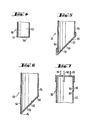
- the membrane 56 spans the opening 78 of the cap 80 and is potted along its circumference with the edge region 82 of the cap 80 which adjoins the opening 78.
- the cap 80 itself is placed on the end region 54 of the nipple 50 and fastened there in a gastight and liquid-tight manner, for example by welding or gluing.
- FIG. 4 shows a further embodiment in which, as in FIG. 3, the plane formed by the peripheral edge of the end region 54 is perpendicular to the longitudinal axis of the nipple 50.
- the membrane 56 which is arranged parallel to the above-mentioned plane. 4
- the membrane 56 is attached directly to the peripheral edge of the end region 54 of the nipple 50, which in turn can be done by gluing or welding.
- FIG. 7 shows a further embodiment of a drip chamber 30, in which the hollow body 42 itself has an opening 88 passing through its wall, which in turn is completely covered with the membrane 56.
- the peripheral edge of the membrane 56 is firmly connected to the peripheral edge of the opening 88, for example by gluing or welding.
- the distance of the upper opening edge 90 from the chamber-side end 52 or its end region 54 is again in the range mentioned above between 0.5-2.5 cm, preferably about 1.5 cm. This relationship also applies to the upper inclined edge 86 in the embodiment according to FIG. 5 and 6.
- a transparent material in particular a transparent plastic with elastic properties, is advantageously chosen as the material for the drip chamber, in which a good optical monitoring of the drip chamber is ensured.
- Plastic materials include, for example, PVC, polycarbonate, polypropylene, polyacrylic glass, polyethylene and the like. in question. Of these materials, PVC is preferred.
- Suitable materials for the membrane 56 are water-impermeable, semi-permeable membranes based on plastic, which are water-impermeable at least up to an excess pressure of 500 mbar. This limit is preferably at least 1, in particular 1.5 bar. In the case of a membrane that can be used, it was measured, for example, that water from blood only passes through above 1.6 bar, while pure water up to 2.75 bar did not pass through. However, these pressures do not occur in the drip chamber in dialysis operation, so that there is sufficient safety space for this operation. Should a membrane actually break, an alarm can be given immediately by a drop in pressure in the pressure manometer 66.
- Organic polymers in particular PTFE (Teflon), silicones, polyethylene, polypropylene, and hydrophobized polymers, for example siliconized polymers, are suitable as plastic materials for such membranes.
- PTFE Teflon
- silicones polyethylene, polypropylene, and hydrophobized polymers, for example siliconized polymers
- PTFE is preferred.
- the semipermeable property is due to a micro-porous structure of the membrane which is usually in the form of a film with a thickness of 0.01-0.3, preferably 0.05-0.1 mm.
- This microporous structure is either formed by a cross network of the polymerized material, whereby an average pore diameter is obtained, or by a channel-shaped arrangement of a plurality of holes.
- the pore diameter of these openings is less than 1 ⁇ m, in particular less than 0.5 ⁇ m.
- a membrane with a pore diameter of about 0.2 ⁇ m is particularly preferred.
- the hydrophobic membrane can also be supported by a support membrane.
- This support membrane the pores of which are considerably larger than that of the hydrophobic membrane, can also be made of a plastic, for example polyester, polyethylene, polypropylene and the like.
- a laminated membrane is arranged on the blood side, ie in the direction of the chamber, while the support layer does not come into contact with the water-containing liquid.
- the thickness of the laminate is advantageously in a range of 0.1-0.3, in particular approximately 0.2 mm.
- the elastic drip chamber 30 can be connected in the dialysis device 10 to a monitoring device 92 which controls the lower level of the blood level, so that a complete regulation of the blood level in the drip chamber 30 can be achieved. As a result, the greatest possible safety is achieved with little expenditure on equipment and simple handling.
Abstract
Description
Die Erfindung betrifft eine Tropfkammer, insbesondere zur Verwendung in einer Hämodialysevorrichtung, die an ihrer Oberseite wenigstens eine Zulauföffnung und an ihrer Unterseite wenigstens eine Ablauföffnung für eine Flüssigkeit, wobei diese Öffnungen mit entsprechenden Zulauf- und Ablaufleitungen verbindbar sind, und eine durch eine Verschlußvorrichtung verschließbare Öffnung zur Entfernung von Gasen aufweist.The invention relates to a drip chamber, in particular for use in a hemodialysis device, which has at least one inlet opening on its upper side and at least one outlet opening for a liquid on its underside, these openings being connectable to corresponding inlet and outlet lines, and an opening which can be closed by a closure device for removing gases.
Tropfkammern der eingangs erwähnten Art werden insbesondere in Vorrichtungen verwendet, in denen entweder der Zufluß einer Flüssigkeit besonders überwacht werden muß oder eine Trennung von mit der Flüssigkeit vermischten Fluiden stromab einer bestimmten Behandlungsvorrichtung erfolgen muß. Die Einhaltung dieser Voraussetzungen ist speziell beim Betrieb einer Dialysevorrichtung zwingend notwendig. In einer derartigen Dialysevorrichtung wird das Blut entlang einer semipermeablen Membran geführt, auf deren Rückseite eine Dialysatflüssigkeit strömt. Diese Dialysatflüssigkeit nimmt die aus dem Blut durch die Membran dringenden Verunreinigungen auf, reinigt somit also das Blut eines Patienten, der an einem Nierenversagen leidet. Das gereinigte Blut wird stromab dieser Dialysemembran über entsprechende Überwachungseinrichtungen wieder zum Patienten zurückgeführt.Drip chambers of the type mentioned at the outset are used in particular in devices in which either the inflow of a liquid has to be particularly monitored or a separation of fluids mixed with the liquid must take place downstream of a specific treatment device. Compliance with these requirements is imperative especially when operating a dialysis machine. In such a dialysis device, the blood is guided along a semipermeable membrane, on the back of which a dialysate liquid flows. This dialysate fluid absorbs the impurities that pass through the membrane through the blood, thus cleaning the blood of a patient who has kidney failure. The purified blood is returned to the patient downstream of this dialysis membrane via appropriate monitoring devices.
Zu diesen Überwachungseinrichtungen gehört die vorstehend erwähnte Tropfkammer, in der die im gesamten System und im Blut befindlichen Gase im wesentlichen abgetrennt und entfernt werden können. Beim Anfahren der Dialysevorrichtung, d.h. bei der Einleitung von Blut in die die semipermeable Membrane enthaltende Austauschvorrichtung, und der darauffolgenden Rückführung des Blutes muß unter allen Umständen vermieden werden, daß anstelle von Blut Luft in den Patienten zurückgeführt wird, da dies zu einer lebensbedrohenden Luftembolie führen kann. In der Tropfkammer, in die das Blut'über eine Zulaufleitung und eine entsprechende Zulauföffnung eingeführt und aus der es durch eine entsprechende Ablauföffnung und eine Ablaufleitung abgeführt wird, kann sowohl die in der gesamten Vorrichtung enthaltene Luft als auch die mit dem Blut mitgerissene und/oder darin enthaltene Luft bzw. Gase getrennt werden. Das sich dabei in der Tropfkammer einstellende Flüssigkeitsniveau, insbesondere das Niveau des Blutes, hängt natürlich von der in der Kammer enthaltenen, über dem Blut liegenden Luftschicht ab.These monitoring devices include the drip chamber mentioned above, in which the gases present in the entire system and in the blood can essentially be separated and removed. When starting the dialysis machine, i.e. when introducing blood into the exchange device containing the semipermeable membrane and the subsequent return of the blood, it must be avoided under all circumstances that air is returned to the patient instead of blood, as this can lead to a life-threatening air embolism. In the drip chamber into which the blood is introduced via an inlet line and a corresponding inlet opening and from which it is discharged through a corresponding outlet opening and an outlet line, both the air contained in the entire device and the air entrained with the blood and / or air or gases contained therein are separated. The level of liquid which arises in the drip chamber, in particular the level of the blood, naturally depends on the air layer contained in the chamber, which lies above the blood.
Infolgedessen ist in der Kammer eine weitere Öffnung vorgesehen, über die sowohl die beim Anfahren der Dialysevorrichtung vorliegende Luft entfernt als auch die Höhe der nach dem Einpegeln des Blutniveaus entstandenen Luftschicht in der Tropfkammer geregelt werden kann. Üblicherweise ist die Öffnung zur Entfernung der Luft mit einer Leitung verbunden, die mit einer entsprechenden Verschlußvorrichtung abgeklemmt ist. Hierdurch wird sichergestellt, daß das Blut durch die Ablauföffnung , zum Patienten zurückgeführt wird und nicht durch die für die Luftabtrennung vorgesehene Öffnung entweicht. Eine derartige Verschlußvorrichtung kann beispielsweise eine Spritze sein, mit der Luft aus der Tropfkammer abgezogen wird. Andrerseits kann jedoch auch eine peristaltische Pumpe, beispielsweise eine Schlauchpumpe, den Luftabführungsschlauch verschließen und durch eine entsprechende Betätigung Luft aus der Tropfkammer abpumpen.As a result, a further opening is provided in the chamber, through which both the air present when the dialysis device is started up and the height of the air layer formed after the blood level has been leveled in the drip chamber can be regulated. The opening for removing air is usually connected to a line which is clamped off with a corresponding closure device. This ensures that the blood is returned to the patient through the drain opening and does not escape through the opening provided for air separation. Such a closure device can be, for example, a syringe with which air is drawn out of the drip chamber. On the other hand, however, a peristaltic pump, for example a peristaltic pump, can close the air discharge hose and pump air out of the drip chamber by appropriate actuation.
Wichtigste Voraussetzung beim Betrieb einer Dialysevorrichtung ist ihr störungsfreier Betrieb, da Dialysepatienten infolge ihres angegriffenen Gesundheitszustandes bereits unter einem erheblichen Streß leiden und auf Störungen der lebenswichtigen Dialysevorrichtung besonders empfindlich reagieren. Insbesondere bei der Heimdialyse, bei der kein Fachpersonal zur Verfügung steht und der Patient selbst die Dialysevorrichtung zu bedienen hat, ist ein einwandfreies Funktionieren mit möglichst wenigen Handgriffen bei der Bedienung der Vorrichtung besonders erstrebenswert.The most important prerequisite for the operation of a dialysis machine is its trouble-free operation, since dialysis patients already suffer from considerable stress due to their attacked state of health and are particularly sensitive to disorders of the vital dialysis machine. In particular in home dialysis, in which no specialist personnel are available and the patient himself has to operate the dialysis device, it is particularly desirable to operate properly with as few steps as possible when operating the device.
Die Tropfkammer des Standes der Technik kann jedoch dieser Forderung nicht vollständig gerecht werden, da in ihr die Höhe der Luftschicht und damit zwangsläufig das Blutniveau mehrmals während der Dialyse nachgestellt werden müssen. Dieses Niveau wird in der Regel durch eine Alarmvorrichtung überwacht, die akustisch den Patienten darauf hinweist, daß eine erneute Überprüfung des Blutniveaus in der Tropfkammer nötig ist,und ggf. die gesamte Vorrichtung abschaltet. Häufig kommt es daher zu mehrmaligem Alarm während einer Behandlung, wodurch der Patient gestört und zur Überprüfung der Vorrichtung und Entfernung der Luft aus der Tropfkammer veranlaßt wird, so daß von einem störungsfreiem Betrieb nicht die Rede sein kann. Diese Störungen treten häufig auf, da während der Dialyse Luft in die Tropfkammer eingeführt werden kann und somit das Blutniveau stetig solange abgesenkt wird, bis die Alarmvorrichtung betätigt wird.However, the drip chamber of the prior art cannot fully meet this requirement, since the height of the air layer and thus the blood level inevitably have to be readjusted several times during dialysis. This level is generally monitored by an alarm device which acoustically advises the patient that the blood level in the drip chamber needs to be checked again and, if necessary, switches off the entire device. Frequently there are repeated alarms during a treatment, which disturbs the patient and causes the device to be checked and the air removed from the drip chamber, so that there can be no question of trouble-free operation. These disorders often occur because air can be introduced into the drip chamber during dialysis and thus the blood level is constantly lowered until the alarm device is activated.
Der Erfindung liegt daher die Aufgabe zu Grunde, eine Tropfkammer der eingangs erwähnten Art zu schaffen, die selbsttätig die Dicke der Luftschicht und somit das Flüssigkeitsniveau im Betrieb konstant hält.The invention is therefore based on the object of creating a drip chamber of the type mentioned at the outset, which automatically keeps the thickness of the air layer and thus the liquid level constant during operation.
pie Lösung der Aufgabe erfolgt dadurch, daß die Öffnung zur Entfernung der Gase mit einer flüssigkeitsabstoßenden, gasdurchlässigen Membran verschlossen ist.pie solution to the problem is achieved in that the opening for removing the gases is closed with a liquid-repellent, gas-permeable membrane.
Bei der erfindungsgemäßen Tropfkammer, die vorzugsweise eine wasserabstoßende Membran aufweist, wird das Blutniveau und das darüberliegende Luftpolster selbsttätig dadurch konstant gehalten, daß die in die Tropfkammer beförderte überflüssige Luft durch die Membran ausgeschieden wird. Dabei pendelt sich das Flüssigkeitsniveau, insbesondere das Blutniveau in Höhe der Membran ein und schließt somit nach oben ein Luftpolster ab. Dieses elastisch wirkende Luftpolster verhindert ein weiteres Ansteigen der Flüssigkeit in der Tropfkammer, da sich mit steigendem Flüssigkeitsspiegel ein Gegendruck im Luftpolster aufbaut, der diesem Anstieg entgegenwirkt. Wenn dieser Gegendruck dem Förderdruck entspricht, der notwendig ist, um das Blut in die Vene des Patienten zurückzuführen, hat das Flüssigkeitsniveau seine Gleichgewichtslage erreicht. Bei dieser Gleichgewichtslage verbleibt es solange, bis der Druck des Luftpolsters, etwa durch Hinzuführung weiterer Luftmengen, ansteigt, was eine Absenkung des Flüssigkeitsniveaus zur Folge hat. Kommt es dann zu einem Absinken des Flüssigkeitsniveaus unter die Membran und erreicht dadurch das Luftpolster wiederum die Membran, so wird solange Luft durch die Membran ausgeschieden, bis das Flüssigkeitsniveau wieder über die Membran angestiegen ist und das Luftpolster erneut eingeschlossen ist. Es folgt dann wieder der gleiche Kreislauf zur Entfernung neu hinzugeführter Luftmengen.In the drip chamber according to the invention, which preferably has a water-repellent membrane, the blood level and the air cushion above it are automatically kept constant in that the excess air conveyed into the drip chamber is excreted through the membrane. The liquid level, in particular the blood level, levels off at the level of the membrane and thus closes off an air cushion at the top. This elastic air cushion prevents the liquid in the drip chamber from rising further, since with increasing liquid level a counter pressure builds up in the air cushion, which counteracts this increase. When this back pressure is equal to the delivery pressure necessary to return the blood to the patient's vein, the fluid level has reached equilibrium. In this equilibrium position, it remains until the pressure of the air cushion rises, for example by adding more air quantities, which results in a lowering of the liquid level. If the liquid level then drops below the membrane and the air cushion reaches the membrane again, air is excreted through the membrane until the liquid level has risen again over the membrane and the air cushion is enclosed again. The same cycle for removal then follows again of air volumes.
Diese selbsttätige Regelung der Luftausscheidung in einer Dialysevorrichtung hat zur Folge, daß die häufig während der Nacht durchgeführte Dialysebehandlung eines Patienten in der Regel ohne Alarm verläuft, da das Luftpolster in der Tropfkammer nicht mehr über eine einmal eingestellte Höhe ansteigen kann. Somit kann sich der Patient in Ruhe der Dialysebehandlung unterziehen und wird nicht durch wiederholte Alarmphasen gestört.This automatic regulation of the air excretion in a dialysis device has the result that the dialysis treatment of a patient, which is frequently carried out during the night, generally proceeds without an alarm, since the air cushion in the drip chamber can no longer rise above a set height. This allows the patient to undergo dialysis treatment in peace and is not disturbed by repeated alarm phases.
Weiterhin entfällt durch die selbsttätige Regulierung der Flüssigkeitshöhe und des Luftpolsters ein weiterer, für Laien nicht einfach zu handhabender Bedienungsschritt, so daß die Bedienbarkeit der Dialysevorrichtung verbessert wird.Furthermore, the automatic regulation of the liquid level and the air cushion eliminates a further operating step, which is not easy for laypersons to handle, so that the operability of the dialysis device is improved.
Weitere Merkmale, Vorteile und Einzelheiten der Erfindung ergeben sich aus der nachfolgenden Beschreibung anhand der in der Zeichnung gezeigten Ausführungsbeispiele.Further features, advantages and details of the invention result from the following description with reference to the exemplary embodiments shown in the drawing.
Es zeigen
- Fig. 1 eine schematische Ansicht einer Dialysevorrichtung unter nicht maßstabsgetreuer Hervorhebung der erfindungsgemäßen Tropfkammer
- Fig. 2a eine erste Ausführungsform der erfindungsgemäßen Tropfkammer im Längsschnitt
- Fig. 2b eine zweite Ausführungsform der erfindungsgemäßen Tropfkammer im Längsschnitt
- Fig. 3 eine Ausführungsform der Membrananordnung gem.
- Fig.2 im Querschnitt vergrößert
- Fig. 4 eine weitere Ausführungsform der Membrananordnung gem. Fig.2 im Querschnitt vergrößert
- Fig. 5 eine dritte Ausführungsform einer Membrananordnung im Querschnitt, die in einer der Tropfkammern gem. Fig.2 einsetzbar ist
- Fig. 6 eine vierte Ausführungsform einer Membrananordnung im Querschnitt, die ebenfalls in einer der in Fig. 2 gezeigten Tropfkammern einsetzbar ist und
- Fig. 7 eine weitere Ausführungsform einer Tropfkammer im Längsschnitt.
- Fig. 1 is a schematic view of a dialysis device with highlighting the drip chamber according to the invention not to scale
- Fig. 2a shows a first embodiment of the drip chamber according to the invention in longitudinal section
- Fig. 2b shows a second embodiment of the drip chamber according to the invention in longitudinal section
- Fig. 3 shows an embodiment of the membrane arrangement.
- Fig.2 enlarged in cross section
- Fig. 4 shows another embodiment of the membrane assembly according. Fig.2 enlarged in cross section
- Fig. 5 shows a third embodiment of a membrane arrangement in cross-section, which in one of the drip chambers acc. Fig.2 can be used
- Fig. 6 shows a fourth embodiment of a membrane arrangement in cross section, which can also be used in one of the drip chambers shown in Fig. 2 and
- Fig. 7 shows another embodiment of a drip chamber in longitudinal section.
In Fig. 1 ist schematisch eine Dialysevorrichtung 10 gezeigt, die üblicherweise zur Hämodialyse von Blut eingesetzt wird. Bei dieser Hämodialyse wird arteriell aus dem Patienten 12 über eine Leitung 14 Blut entnommen, wobei eine peristaltische Pumpe 16, üblicherweise eine Schlauchpumpe diese Blutentnahme unterstützt. Hierdurch entsteht in der Leitung 14 ein Unterdruck im Bereich von etwa 100 mbar, der durch ein Druckmanometer 18 angezeigt werden kann. Stromab der peristaltischen Pumpe 16 kann über eine Spritze 20 eine Hilfsflüssigkeit, beispielsweise Heparin, dem Blut zugeführt werden, um beispielsweise die Blutgerinnung zu hemmen. Die Leitung 14 ist hinter der Spritze 20 mit dem Dialysator 22 verbunden. Dieser Dialysator 22 enthält eine nicht dargestellte semipermeable Dialysemembran, an deren einen Seite das Blut über die Leitung 14 vorbeigeführt wird, während auf ihrer anderen Seite eine Spülflüssigkeit, die aus einer gewöhnlichen Kochsalzlösung mit gewissen medizinischen Zusätzen bestehen kann, über die Leitung 24 zugeführt und über die Leitung 26 entfernt wird.In Fig. 1 a
Der blutseitige Ausgang des Dialysators 22 ist über die Leitung 28 mit der erfindungsgemäßen Tropfkammer 30 verbunden, so daß das Blut direkt in diese Tropfkammer 30 geführt wird, wenn es den Dialysator 22 durchlaufen hat.The blood-side outlet of the
Nach dem Durchlaufen der Tropfkammer 30 wird das Blut über die Leitung 32, die ggf. eine spezielle Luftabscheidevorrichtung 34 enthalten kann, zum Patienten 12 zurückgeführt.After passing through the
Es ist anzumerken, daß auf der arteriellen Seite der Blutführung ein Überdruck von ca. 100 mbar vorliegt, der auf die Wirkung der Pumpe 16 zurückzuführen ist. Diese Pumpe 16 kann auf ihrer Saugseite natürlich auch etwas Luft ansaugen, die in der Dialysevorrichtung 10 selbst entfernt werden muß, um eine Luftembolie des Patienten zu unterdrücken. Die Überwachung des Luftzuflusses und Einstellung des Blutzuflusses läßt sich vorteilhaft in der Tropfkammer 30 durchführen, die nachstehend unter Bezugnahme auf die Fig. 1 in Verbindung mit Fig. 2 erläutert wird.It should be noted that there is an overpressure of approximately 100 mbar on the arterial side of the blood supply, which is due to the action of the
Das gereinigte Blut wird, wie vorstehend festgestellt, über die Leitung 28 der Tropfkammer 30 zugeführt, die vorteilhafterweise einen Nippel 36 aufweist, der zum Anschluß der Leitung 28 dient. Dieser Nippel 36 befindet sich auf einer Kappe 38, deren Umfangsränder 40 den die Kammer bildenden Hohlkörper 42 gasdicht umfassen. Die Kappe 38 kann jedoch auch als ebener Deckel ausgebildet sein, der gasdicht auf den Hohlkörper 42 aufgesetzt ist. Um eine gasdichte Verbindung der Kappe 38 mit dem Hohlkörper 42 zu erhalten, können diese miteinander verklebt oder verschmolzen sein.The cleaned blood, as stated above, is fed via
Der Hohlkörper 42 selbst, der vorteilhafterweise zylindrisch ausgebildet ist, weist einen Boden 44 auf, der vorteilhafterweise sich kegelförmig nach unten verjüngt. Dieser Boden 44 wird von der Öffnung 46 eines Abzugsnippels 48 durchsetzt, der an die Leitung 32 angeschlossen werden kann.The
Der Nippel 36 durchsetzt die Kappe 38 und ragt mit seiner Spitze 43 etwas in den Hohlkörper 42. Aus dieser Spitze 43 strömt beim Betrieb der Dialysevorrichtung das Blut in den Hohlkörper 42 ein und steigt zunächst im Hohlkörper 42, wie in Fig. 2b gezeigt ist, hoch, da ein Weiterfließen des Blutes durch die Öffnung 46 in die Leitung 32 zum Patienten durch den Strömungswiderstand darin verhindert wird.The
ein In der Kappe 38 ist weiterer Nippel 50 vorgesehen, der diese Kappe durchsetzt, wobei dieser Nippel 50 mit seinem kammerseitigen Ende 52 weiter in den Hohlkörper 42 ragt als die Spitze 43 des Nippels 36. Vorteilhafterweise beträgt der Höhenunterschied zwischen dem kammerseitigen Ende 52 und der Spitze 43 etwa 0,5 - 2,5 cm, insbesondere etwa 1,5 cm.A
Der Nippel 50 ist natürlich wie die Nippel 36 und 48 innen hohl, so daß bei einem Ansteigen des Blutes in dem Hohlkörper 42 die sich im Hohlkörper 42 befindliche Luft durch ihn hindurch entweichen kann. Wäre der Nippel 50 nicht an seinem kammerseitigen Ende 52 verschlossen, so würde das Blut beim Erreichen des Endbereichs 54 des Nippels 50 die Luftverdrängung beenden und selbst durch den Nippel 50 austreten, was unter allen Umständen verhindert werden muß.The
Daher ist der als Umfangsrand ausgebildete Endbereich 54 mit einer Membran 56 versehen, die einerseits luftdurchlässig ist, andrerseits jedoch hydrophob, d.h. wasserabstoßend ist. Diese Membran 56 läßt also beim Befüllen des Hohlkörpers 42 solange die überschüssige Luft durch, bis das Blut, wie in Fig. 2b gezeigt ist, den Endbereich 54 des Nippels 50 erreicht hat. Da die semipermeable Membran 56 kein Wasser, also auch nicht Blut durchläßt, wird das im Raum 58 eingeschlossene Luftvolumen solange elastisch komprimiert, bis der sich in dem entstandenen Luftpolster aufbauende Gegendruck größer wird als der Strömungswiderstand in der Leitung 32. Dadurch wird ein druckausgeglichenes System geschaffen, bei dem das Niveau 60 des Blutspiegels nur geringfügig schwankt. Wenn nämlich durch geringfügige Mengen Luft das Luftpolster im Raum 58 anwächst und das Niveau 60 nach unten drückt, geht diese Absenkung nur bis zur Höhe der Membran 56, da dann anschließend die Luft durch die Membran 56 entweichen kann. Somit entspricht die Fallhöhe des Blutes dem vorstehend genannten Höhenunterschied zwischen dem Endbereich 54 des Nippels 50 und der Spitze 43 des Nippels 36. Diese Fallhöhe soll den vorstehend genannten Maßen entsprechen, die gewährleisten, daß das Blut einerseits optisch gut überwacht werden kann, andrerseits aber jedoch nicht zuviel Luft aus dem Raum 58 beim Fall mitreißt, was zu einer unerwünschten Luftblasenbildung im Blutraum 62 führen kann.The
In Fig. 2b ist eine weitere Ausführungsform einer erfindungsgemäßen Tropfkammer 30 gezeigt. Diese Tropfkammer 30 weist neben den bereits vorstehend genannten Nippeln 36, 48 und 50 einen weiteren Nippel 63 auf, der gem. Fig. 1 über eine Leitung 64 mit einem Druckmänometer 66 verbunden sein kann. Dieses Druckmanometer 66 zeigt direkt den im Raum 58 befindlichen Luftdruck an und kann über eine nicht gezeigte Alarmvorrichtung Alarm auslösen, sofern der Druck übermäßig ansteigt oder abfällt. Weiterhin kann die Tropfkammer 30 einen vierten Nippel 68 aufweisen, der über eine Leitung 70 mit einer Schlauchpumpe 72 und ggf. mit einer Spritze 74 verbunden sein kann. Die Schlauchpumpe 72, die vorteilhafterweise handbetrieben sein kann, dient zur rascheren Entfernung der Luft beim Anfahren und/oder während des Betriebs der Dialysevorrichtung 10. Durch diese Schlauchpumpe 72 kann somit Luft rasch entzogen oder aber auch zugeführt werden. Dies kann auch durch eine Spritze 74 erfolgen, die mit der Leitung 70 in Verbindung steht.A further embodiment of a
Jedoch ist der Einsatzbereich der Spritze 74 nicht auf die Luftentfernung beschränkt. Vielmehr kann über die Spritze 74 vorteilhafterweise auch eine Flüssigkeit zu- ; geführt werden, die dem Blut beigemischt werden soll.However, the area of use of syringe 74 is not limited to air removal. Rather, a liquid can advantageously also be added via the syringe 74; to be added to the blood.
Die gem. Fig. 2bgezeigte Ausführungsform weist ein am Boden 44 angeordnetes feines Sieb 76 auf, das zylinderförmig auf dem Boden 44 angeordnet ist und mit dem Umfangsrand der Öffnung 46 verbunden ist. Beim Abfluß muß das Blut somit das Sieb, dessen Maschenweite etwa 40 - 200 pm beträgt, durchfließen, so daß darin geronnene Teilchen hängenbleiben.The acc. FIG. 2 b embodiment has a
Nachstehend wird die Membrananordnung unter Bezugnahme auf Fig. 3 - 6 beschrieben.The membrane assembly will now be described with reference to FIGS. 3-6.
Gem. Fig. 3 überspannt die Membran 56 die Öffnung 78 der Kappe 80 und ist entlang ihres Umfangs mit dem sich an die Öffnung 78 anschließenden Randbereichs 82 der Kappe 80 vergossen. Die Kappe 80 selbst ist auf den Endbereich 54 des Nippels 50 aufgesetzt und dort gas-und flüssigkeitsdicht befestigt, beispielsweise durch Verschweißen oder Verkleben.According to FIG. 3, the
In Fig. 4 ist eine weitere Ausführungsform gezeigt, bei der ebenfalls wie in Fig. 3 die durch den Umfangsrand des Endbereichs 54 gebildete Ebene senkrecht zur Längsachse des Nippels 50 steht. Somit trifft das Niveau 60 des Blutes vollständig auf die Membran 56 auf, die parallel zu der vorstehend genannten Ebene angeordnet ist. Gem. Fig. 4 ist die Membran 56 direkt auf dem Umfangsrand des Endbereichs 54 des Nippels 50 befestigt, was wiederum durch Aufkleben oder Aufschweißen erfolgen kann.FIG. 4 shows a further embodiment in which, as in FIG. 3, the plane formed by the peripheral edge of the
In Fig. 5 und 6 sind Anordnungen gezeigt, die im wesentlichen den Anordnungen gem. Fig. 3 bzw. 4 entsprechen, mit der Ausnahme, daß die durch den Umfangsrand des Endbereichs 54 des Nippels 50 gebildete Ebene schräg zur Längsachse des Nippels 50 angeordnet ist. Der von der Längsachse auf dieser Ebene gebildete Winkel liegt vorzugsweise in einem Bereich von 30 - 60, insbesondere etwa 45°. Diese Schräganordnung hat den Vorteil, daß die Regulierung des Niveaus 60 nicht sofort gestoppt wird, wenn dieses Niveau 60 mit den Umfangsrändern des Endbereichs 54 zusammenfällt, sondern daß das Niveau 60 zuerst auf den unteren Schrägrand 84 auftrifft und allmählich an der Membran 56 hochsteigt. Erst wenn der obere Schrägrand 86 erreicht ist, wird die Luftausscheidung gestoppt, so daß auch geringe Überschußmengen an Luft auch mit dieser Anordnung entfernt werden können.5 and 6, arrangements are shown which are essentially the arrangements according to. 3 and 4 correspond, with the exception that the plane formed by the peripheral edge of the
In Fig. 7 ist eine weitere Ausführungsform einer Tropfkammer 30 gezeigt, bei der der Hohlkörper 42 selbst eine seine Wand durchsetzende Öffnung 88 aufweist, die wiederum vollständig mit der Membran 56 bedeckt ist. Der Umfangsrand der Membran 56 ist mit dem Umfangsrand der Öffnung 88 fest verbunden, beispielsweise durch Verkleben oder Verschweißen. Der Abstand des oberen Öffnungsrandes 90 vom kammerseitigen Ende 52 bzw. dessen Endbereich 54 liegt wiederum im vorstehend genannten Bereich zwischen 0,5 - 2,5 cm, vorzugsweise etwa 1,5 cm. Diese Beziehung gilt auch für den oberen Schrägrand 86 bei der Ausführungsform gem. Fig. 5 und 6.FIG. 7 shows a further embodiment of a
Als Material für die Tropfkammer wird vorteilhafterweise ein transparentes Material, insbesondere ein durchsichtiger Kunststoff mit elastischen Eigenschaften gewählt, bei dem eine gute optische Überwachung der Tropfkammer - 30 gewährleistet ist. Als Kunststoffmaterialien kommen beispielsweise PVC, Polycarbonat, Polypropylen, Polyacryl-Glas, Polyethylen u.dgl. in Frage. Von diesen Materialien ist PVC bevorzugt.A transparent material, in particular a transparent plastic with elastic properties, is advantageously chosen as the material for the drip chamber, in which a good optical monitoring of the drip chamber is ensured. Plastic materials include, for example, PVC, polycarbonate, polypropylene, polyacrylic glass, polyethylene and the like. in question. Of these materials, PVC is preferred.
Als Materialien für die Membran 56 kommen wasserundurchlässige, semipermeable Membranen auf Kunststoffbasis in Frage, die wenigstens bis zu einem überdruck von 500 mbar wasserundurchlässig sind. Vorzugsweise beträgt diese Grenze wenigstens 1, insbesondere 1,5 bar. Bei einer einsetzbaren Membran wurde beispielsweise gemessen, daß Wasser aus Blut erst oberhalb 1,6 bar durchtritt, während reines Wasser bis 2,75 bar überhaupt nicht durchgetreten ist. Diese Drücke treten jedoch keinesfalls bei der Tropfkammer im Dialysebetrieb auf, so daß ein ausreichender Sicherheitsraum für diesen Betrieb vorhanden ist. Sollte tatsächlich eine Membran reißen, so kann durch Druckabfall im Druckmanometer 66 sofort Alarm gegeben werden.Suitable materials for the
Als Kunststoffmaterialien für derartige Membranen kommen organische Polymere, insbesondere PTFE (Teflon), Silikone, Polyethylen, Polypropylen, sowie hydrophobierte Polymere, beispielsweise silikonisierte Polymere, in Frage. Von diesen Polymeren ist PTFE bevorzugt.Organic polymers, in particular PTFE (Teflon), silicones, polyethylene, polypropylene, and hydrophobized polymers, for example siliconized polymers, are suitable as plastic materials for such membranes. Of these polymers, PTFE is preferred.
Die semipermeable Eigenschaft ist auf eine mikoporöse Struktur der üblicherweise in Folienform mit einer Dicke von 0,01 - 0,3, vorzugsweise 0,05 - 0,1 mm vorliegenden Membran zurückzuführen. Diese mikroporöse Struktur wird entweder durch ein Kreuznetzwerk des polymerisierten Materials gebildet, wobei ein mittlerer Porendurchmesser erhalten wird, oder durch eine kanalförmige Anordnung einer Vielzahl von Löchern erzeugt. In der Regel liegt der Porendurchmesser dieser öffnungen unter 1 µm, insbesondere unter 0,5 µm. Besonders bevorzugt ist eine Membran mit einem Porendurchmesser von etwa 0,2Jum.The semipermeable property is due to a micro-porous structure of the membrane which is usually in the form of a film with a thickness of 0.01-0.3, preferably 0.05-0.1 mm. This microporous structure is either formed by a cross network of the polymerized material, whereby an average pore diameter is obtained, or by a channel-shaped arrangement of a plurality of holes. As a rule, the pore diameter of these openings is less than 1 µm, in particular less than 0.5 µm. A membrane with a pore diameter of about 0.2 μm is particularly preferred.
Aus Gründen der Festigkeit kann die hydrophobe Membran auch durch eine Stützmembran abgestützt sein. Diese Stützmembran, deren Poren erheblich größer sind als die der hydrophoben Membran kann ebenfalls aus einem Kunststoff, beispielsweise Polyester, Polyethylen, Polypropylen und dergleichen, hergestellt sein. In der erfindungsgemäßen Tropfkammer wird eine derartige laminierte Membran blutseitig, d.h. in Richtung auf die Kammer angeordnet, während die Stützschicht nicht mit der wasserhaltigen Flüssigkeit in Berührung kommt. Vorteilhafterweise liegt die Dicke des Laminats in einem Bereich von 0,1 - 0,3, insbesondere etwa 0,2 mm.For reasons of strength, the hydrophobic membrane can also be supported by a support membrane. This support membrane, the pores of which are considerably larger than that of the hydrophobic membrane, can also be made of a plastic, for example polyester, polyethylene, polypropylene and the like. In the drip chamber according to the invention, such a laminated membrane is arranged on the blood side, ie in the direction of the chamber, while the support layer does not come into contact with the water-containing liquid. The thickness of the laminate is advantageously in a range of 0.1-0.3, in particular approximately 0.2 mm.
Die elastische Tropfkammer 30 kann in der Dialysevorrichtung 10 mit einer überwachungsvorrichtung 92 verbunden werden, die das untere Niveau des Blutspiegels kontrolliert, so daß eine vollständige Regulierung des Blutniveauspiegels in der Tropfkammer 30 erreicht werden kann. Hierdurch wird eine größtmögliche Sicherheit bei geringem apparativem Aufwand und einfacher Handhabbarkeit erreicht.The
Claims (14)
Applications Claiming Priority (2)
| Application Number | Priority Date | Filing Date | Title |
|---|---|---|---|
| DE3115299 | 1981-04-15 | ||
| DE3115299A DE3115299C2 (en) | 1981-04-15 | 1981-04-15 | Drip chamber |
Publications (2)
| Publication Number | Publication Date |
|---|---|
| EP0062913A1 true EP0062913A1 (en) | 1982-10-20 |
| EP0062913B1 EP0062913B1 (en) | 1986-09-17 |
Family
ID=6130232
Family Applications (1)
| Application Number | Title | Priority Date | Filing Date |
|---|---|---|---|
| EP82103060A Expired EP0062913B1 (en) | 1981-04-15 | 1982-04-08 | Drip chamber |
Country Status (5)
| Country | Link |
|---|---|
| EP (1) | EP0062913B1 (en) |
| JP (1) | JPS5810062A (en) |
| BR (1) | BR8202160A (en) |
| DE (1) | DE3115299C2 (en) |
| ES (1) | ES8303923A1 (en) |
Cited By (16)
| Publication number | Priority date | Publication date | Assignee | Title |
|---|---|---|---|---|
| EP0122604A1 (en) * | 1983-04-13 | 1984-10-24 | Fresenius AG | Apparatus for regulating ultrafiltration rate |
| GB2157586A (en) * | 1984-04-24 | 1985-10-30 | Sev Trent Water Authority | Air valves in water supply and distribution systems |
| EP0165519A2 (en) * | 1984-06-18 | 1985-12-27 | Gambro Lundia AB | A blood filtering system |
| EP0612534A1 (en) * | 1993-02-24 | 1994-08-31 | Chen Yueh-Horng | Device for use in controlling intravenous drip |
| WO1996004944A1 (en) * | 1994-08-15 | 1996-02-22 | Gambro Ab | Drip chamber head |
| WO1997040870A1 (en) * | 1996-05-01 | 1997-11-06 | Pall Corporation | Priming system |
| US5779674A (en) * | 1996-05-06 | 1998-07-14 | Mallinckrodt Medical, Inc. | Fluid gas removal drip chamber |
| WO2001041854A3 (en) * | 1999-12-10 | 2002-02-21 | Vapotherm Inc | Apparatus and method for respiratory tract therapy |
| WO2003037402A2 (en) | 2001-10-31 | 2003-05-08 | Daniel Schneditz | Extracorporeal device for treating human blood |
| EP1586345A1 (en) * | 1999-12-10 | 2005-10-19 | Vapotherm, Inc. | Apparatus and method for respiratory tract therapy |
| EP1762258A1 (en) * | 2005-09-08 | 2007-03-14 | Hidex S.R.L. | Infusion apparatus with drip chamber having capacitance based liquid level monitoring |
| EP1395311B1 (en) | 2001-06-05 | 2008-01-02 | Gambro Lundia AB | Method for filling and washing a filter for a dialysis machine |
| US7708013B2 (en) | 2000-12-08 | 2010-05-04 | Vapotherm, Inc. | Apparatus and method for delivering water vapor to a gas |
| US7827981B2 (en) | 2003-01-29 | 2010-11-09 | Vapotherm, Inc. | Method for reducing the work of breathing |
| EP2468321A1 (en) * | 2010-12-21 | 2012-06-27 | Fresenius Medical Care Deutschland GmbH | Chamber for a blood treatment system, use of the chamber, blood tube system and blood treatment system |
| US10625009B2 (en) | 2016-02-17 | 2020-04-21 | Baxter International Inc. | Airtrap, system and method for removing microbubbles from a fluid stream |
Families Citing this family (5)
| Publication number | Priority date | Publication date | Assignee | Title |
|---|---|---|---|---|
| DE3302804C2 (en) * | 1983-01-28 | 1985-03-14 | Fresenius AG, 6380 Bad Homburg | Device for removing water from blood |
| DE3333362C2 (en) * | 1983-09-15 | 1986-03-20 | Fresenius AG, 6380 Bad Homburg | Peritoneal dialysis machine |
| DE3832028A1 (en) * | 1988-09-21 | 1990-03-22 | Minh Bach Dr Ing Dr Med Quang | DEVICE FOR VENTING LIQUIDS FLOWING IN MEDICAL LIQUID SYSTEMS |
| JP2003093503A (en) * | 2001-09-25 | 2003-04-02 | Jms Co Ltd | Automatic degassing system for blood circuit |
| DE102020112224A1 (en) * | 2020-05-06 | 2021-11-11 | Fresenius Medical Care Deutschland Gmbh | Degassing device |
Citations (5)
| Publication number | Priority date | Publication date | Assignee | Title |
|---|---|---|---|---|
| US3042038A (en) * | 1958-03-14 | 1962-07-03 | Cutter Lab | Segregation chamber and flow meter |
| GB2000685A (en) * | 1977-07-08 | 1979-01-17 | Johnson & Johnson | Vented filter assembly |
| DE2851838A1 (en) * | 1977-11-30 | 1979-05-31 | Baxter Travenol Lab | GAS SEPARATION AND VENTILATION FILTER UNIT AND METHOD FOR ATTACHING A FILTER ELEMENT |
| US4177149A (en) * | 1978-07-21 | 1979-12-04 | Pall Corporation | Filter assembly for intravenous liquid administration apparatus |
| GB2028976A (en) * | 1978-08-28 | 1980-03-12 | Sis Ter Spa | Device for stopping a liquid flow in the presence of gas bubbles |
Family Cites Families (3)
| Publication number | Priority date | Publication date | Assignee | Title |
|---|---|---|---|---|
| DE2634121C2 (en) * | 1975-08-28 | 1983-05-05 | Helmut Dr. 6020 Innsbruck Biedermann | Drip chamber |
| US4256103A (en) * | 1978-10-11 | 1981-03-17 | James Paxinos | Automatic sequential fluid flow apparatus |
| US4237879A (en) * | 1979-02-28 | 1980-12-09 | Abbott Laboratories | Equipment sets for the sequential administration of medical liquids at dual flow rates employing parallel secondary liquid tubing and a 3-way valve |
-
1981
- 1981-04-15 DE DE3115299A patent/DE3115299C2/en not_active Expired
-
1982
- 1982-04-08 EP EP82103060A patent/EP0062913B1/en not_active Expired
- 1982-04-12 JP JP57060825A patent/JPS5810062A/en active Granted
- 1982-04-14 BR BR8202160A patent/BR8202160A/en not_active IP Right Cessation
- 1982-04-15 ES ES511446A patent/ES8303923A1/en not_active Expired
Patent Citations (5)
| Publication number | Priority date | Publication date | Assignee | Title |
|---|---|---|---|---|
| US3042038A (en) * | 1958-03-14 | 1962-07-03 | Cutter Lab | Segregation chamber and flow meter |
| GB2000685A (en) * | 1977-07-08 | 1979-01-17 | Johnson & Johnson | Vented filter assembly |
| DE2851838A1 (en) * | 1977-11-30 | 1979-05-31 | Baxter Travenol Lab | GAS SEPARATION AND VENTILATION FILTER UNIT AND METHOD FOR ATTACHING A FILTER ELEMENT |
| US4177149A (en) * | 1978-07-21 | 1979-12-04 | Pall Corporation | Filter assembly for intravenous liquid administration apparatus |
| GB2028976A (en) * | 1978-08-28 | 1980-03-12 | Sis Ter Spa | Device for stopping a liquid flow in the presence of gas bubbles |
Cited By (29)
| Publication number | Priority date | Publication date | Assignee | Title |
|---|---|---|---|---|
| EP0122604A1 (en) * | 1983-04-13 | 1984-10-24 | Fresenius AG | Apparatus for regulating ultrafiltration rate |
| GB2157586A (en) * | 1984-04-24 | 1985-10-30 | Sev Trent Water Authority | Air valves in water supply and distribution systems |
| EP0165519A2 (en) * | 1984-06-18 | 1985-12-27 | Gambro Lundia AB | A blood filtering system |
| EP0165519A3 (en) * | 1984-06-18 | 1987-05-06 | Gambro Lundia Ab | A blood filtering system |
| EP0354597A2 (en) | 1984-06-18 | 1990-02-14 | Gambro Lundia AB | Use of a drip and/or expansion chamber |
| EP0354597A3 (en) * | 1984-06-18 | 1990-06-13 | Gambro Lundia AB | Use of a drip and/or expansion chamber |
| EP0612534A1 (en) * | 1993-02-24 | 1994-08-31 | Chen Yueh-Horng | Device for use in controlling intravenous drip |
| US5851202A (en) * | 1994-08-15 | 1998-12-22 | Gambro Ab | Drip chamber head |
| WO1996004944A1 (en) * | 1994-08-15 | 1996-02-22 | Gambro Ab | Drip chamber head |
| WO1997040870A1 (en) * | 1996-05-01 | 1997-11-06 | Pall Corporation | Priming system |
| AU728816B2 (en) * | 1996-05-01 | 2001-01-18 | Pall Corporation | Priming system |
| US6336916B1 (en) | 1996-05-01 | 2002-01-08 | Pall Corporation | Priming system |
| US5779674A (en) * | 1996-05-06 | 1998-07-14 | Mallinckrodt Medical, Inc. | Fluid gas removal drip chamber |
| WO2001041854A3 (en) * | 1999-12-10 | 2002-02-21 | Vapotherm Inc | Apparatus and method for respiratory tract therapy |
| EP1586345A1 (en) * | 1999-12-10 | 2005-10-19 | Vapotherm, Inc. | Apparatus and method for respiratory tract therapy |
| US7314046B2 (en) | 1999-12-10 | 2008-01-01 | Vapotherm, Inc. | Apparatus and method for respiratory tract therapy |
| US7708013B2 (en) | 2000-12-08 | 2010-05-04 | Vapotherm, Inc. | Apparatus and method for delivering water vapor to a gas |
| EP1395311B2 (en) † | 2001-06-05 | 2017-03-15 | Gambro Lundia AB | Method for filling and washing a filter for a dialysis machine |
| EP1395311B1 (en) | 2001-06-05 | 2008-01-02 | Gambro Lundia AB | Method for filling and washing a filter for a dialysis machine |
| WO2003037402A2 (en) | 2001-10-31 | 2003-05-08 | Daniel Schneditz | Extracorporeal device for treating human blood |
| US7827981B2 (en) | 2003-01-29 | 2010-11-09 | Vapotherm, Inc. | Method for reducing the work of breathing |
| EP1762258A1 (en) * | 2005-09-08 | 2007-03-14 | Hidex S.R.L. | Infusion apparatus with drip chamber having capacitance based liquid level monitoring |
| EP2468321A1 (en) * | 2010-12-21 | 2012-06-27 | Fresenius Medical Care Deutschland GmbH | Chamber for a blood treatment system, use of the chamber, blood tube system and blood treatment system |
| WO2012084208A1 (en) * | 2010-12-21 | 2012-06-28 | Fresenius Medical Care Deutschland Gmbh | Chamber for a blood treatment system, use of the chamber, blood tube system and blood treatment system |
| AU2011348424B2 (en) * | 2010-12-21 | 2016-03-31 | Fresenius Medical Care Deutschland Gmbh | Chamber for a blood treatment system, use of the chamber, blood tube system and blood treatment system |
| EA026130B1 (en) * | 2010-12-21 | 2017-03-31 | Фрезениус Медикел Кэар Дойчланд Гмбх | Chamber for blood treatment tubing system, use of the chamber and blood treatment tubing system |
| US9931455B2 (en) | 2010-12-21 | 2018-04-03 | Fresenius Medical Care Deutschland Gmbh | Chamber for blood treatment system, use of the chamber, blood tubing system and blood treatment system |
| US10195335B2 (en) | 2010-12-21 | 2019-02-05 | Fresenius Medical Care Deutschland Gmbh | Chamber for blood treatment system and method using same |
| US10625009B2 (en) | 2016-02-17 | 2020-04-21 | Baxter International Inc. | Airtrap, system and method for removing microbubbles from a fluid stream |
Also Published As
| Publication number | Publication date |
|---|---|
| ES511446A0 (en) | 1983-02-16 |
| DE3115299A1 (en) | 1982-11-04 |
| BR8202160A (en) | 1983-03-29 |
| JPH0347871B2 (en) | 1991-07-22 |
| ES8303923A1 (en) | 1983-02-16 |
| JPS5810062A (en) | 1983-01-20 |
| EP0062913B1 (en) | 1986-09-17 |
| DE3115299C2 (en) | 1984-08-16 |
Similar Documents
| Publication | Publication Date | Title |
|---|---|---|
| EP0062913B1 (en) | Drip chamber | |
| DE3302804C2 (en) | Device for removing water from blood | |
| DE2835230C2 (en) | Device for intravenous administration of a liquid | |
| EP3294244B1 (en) | System for treatment of wounds using serum | |
| DE69724948T2 (en) | BREATHER DEVICE | |
| DE102005001779B4 (en) | Disposable for operating a blood treatment device in single-needle or two-needle operation | |
| DE19620591B4 (en) | Device for removing gases from liquids | |
| EP0631789B1 (en) | Device for gaseous exchange especially for oxygenating blood | |
| DE2821482C3 (en) | Filter unit and its use in an infusion system | |
| DE69133161T9 (en) | venting system | |
| DE60033846T2 (en) | DRIP CHAMBER WITH MEMBRANE MOUNTING ARRANGEMENT | |
| DE2818390C2 (en) | Artificial organ | |
| DE2461489C2 (en) | Oxygenator for blood with a holding device | |
| DE69635364T2 (en) | Blood filter and extracorporeal circulation | |
| DE3215003A1 (en) | Dialysis apparatus having improved air separation | |
| EP1912688B1 (en) | Vapour-sterisable blood separating device | |
| DE3223446C2 (en) | Air-free artificial kidney assembly with a degassing device | |
| EP0454178A1 (en) | Autotransfusion apparatus | |
| DE2121740A1 (en) | Pressure transducer | |
| CH627947A5 (en) | FILTER DEVICE. | |
| DE2458405A1 (en) | FILTER HOLDER | |
| DE2611212A1 (en) | DEVICE FOR TREATMENT OF WATER ADDICTION (ASZITES) | |
| WO2016181300A1 (en) | Wound dressing system | |
| DE60220220T2 (en) | Blood treatment system | |
| DE3418434A1 (en) | METHOD FOR FILLING A BLOOD HOSE SYSTEM OF A HAEMODIALYSIS DEVICE WITH A PHYSIOLOGICAL SALINE SOLUTION, AND DEVICE THEREFOR |
Legal Events
| Date | Code | Title | Description |
|---|---|---|---|
| PUAI | Public reference made under article 153(3) epc to a published international application that has entered the european phase |
Free format text: ORIGINAL CODE: 0009012 |
|
| AK | Designated contracting states |
Designated state(s): BE FR GB IT NL |
|
| 17P | Request for examination filed |
Effective date: 19821215 |
|
| GRAA | (expected) grant |
Free format text: ORIGINAL CODE: 0009210 |
|
| AK | Designated contracting states |
Kind code of ref document: B1 Designated state(s): BE FR GB IT NL |
|
| ET | Fr: translation filed | ||
| ITF | It: translation for a ep patent filed |
Owner name: SOCIETA' ITALIANA BREVETTI S.P.A. |
|
| PLBE | No opposition filed within time limit |
Free format text: ORIGINAL CODE: 0009261 |
|
| STAA | Information on the status of an ep patent application or granted ep patent |
Free format text: STATUS: NO OPPOSITION FILED WITHIN TIME LIMIT |
|
| 26N | No opposition filed | ||
| ITTA | It: last paid annual fee | ||
| PGFP | Annual fee paid to national office [announced via postgrant information from national office to epo] |
Ref country code: GB Payment date: 19930319 Year of fee payment: 12 |
|
| PGFP | Annual fee paid to national office [announced via postgrant information from national office to epo] |
Ref country code: FR Payment date: 19930417 Year of fee payment: 12 |
|
| PGFP | Annual fee paid to national office [announced via postgrant information from national office to epo] |
Ref country code: NL Payment date: 19930430 Year of fee payment: 12 |
|
| PGFP | Annual fee paid to national office [announced via postgrant information from national office to epo] |
Ref country code: BE Payment date: 19930504 Year of fee payment: 12 |
|
| PG25 | Lapsed in a contracting state [announced via postgrant information from national office to epo] |
Ref country code: GB Effective date: 19940408 |
|
| PG25 | Lapsed in a contracting state [announced via postgrant information from national office to epo] |
Ref country code: BE Effective date: 19940430 |
|
| BERE | Be: lapsed |
Owner name: FRESENIUS A.G. Effective date: 19940430 |
|
| PG25 | Lapsed in a contracting state [announced via postgrant information from national office to epo] |
Ref country code: NL Effective date: 19941101 |
|
| GBPC | Gb: european patent ceased through non-payment of renewal fee |
Effective date: 19940408 |
|
| NLV4 | Nl: lapsed or anulled due to non-payment of the annual fee | ||
| PG25 | Lapsed in a contracting state [announced via postgrant information from national office to epo] |
Ref country code: FR Effective date: 19941229 |
|
| REG | Reference to a national code |
Ref country code: FR Ref legal event code: ST |