EP0063830A1 - Device for detecting the position of an object - Google Patents
Device for detecting the position of an object Download PDFInfo
- Publication number
- EP0063830A1 EP0063830A1 EP82200364A EP82200364A EP0063830A1 EP 0063830 A1 EP0063830 A1 EP 0063830A1 EP 82200364 A EP82200364 A EP 82200364A EP 82200364 A EP82200364 A EP 82200364A EP 0063830 A1 EP0063830 A1 EP 0063830A1
- Authority
- EP
- European Patent Office
- Prior art keywords
- prism
- radiation
- detectors
- refracting edge
- subdetectors
- Prior art date
- Legal status (The legal status is an assumption and is not a legal conclusion. Google has not performed a legal analysis and makes no representation as to the accuracy of the status listed.)
- Granted
Links
- 230000005855 radiation Effects 0.000 claims abstract description 75
- 238000001514 detection method Methods 0.000 claims abstract description 29
- 238000011896 sensitive detection Methods 0.000 claims abstract description 7
- 230000001419 dependent effect Effects 0.000 claims description 2
- 238000006073 displacement reaction Methods 0.000 description 13
- 238000005259 measurement Methods 0.000 description 7
- 230000003287 optical effect Effects 0.000 description 4
- 239000000969 carrier Substances 0.000 description 3
- 230000035945 sensitivity Effects 0.000 description 2
- 241000276420 Lophius piscatorius Species 0.000 description 1
- 238000010276 construction Methods 0.000 description 1
- 230000007423 decrease Effects 0.000 description 1
- 239000012530 fluid Substances 0.000 description 1
- 239000011241 protective layer Substances 0.000 description 1
- 239000004575 stone Substances 0.000 description 1
- 239000000758 substrate Substances 0.000 description 1
Images
Classifications
-
- G—PHYSICS
- G11—INFORMATION STORAGE
- G11B—INFORMATION STORAGE BASED ON RELATIVE MOVEMENT BETWEEN RECORD CARRIER AND TRANSDUCER
- G11B7/00—Recording or reproducing by optical means, e.g. recording using a thermal beam of optical radiation by modifying optical properties or the physical structure, reproducing using an optical beam at lower power by sensing optical properties; Record carriers therefor
- G11B7/08—Disposition or mounting of heads or light sources relatively to record carriers
- G11B7/09—Disposition or mounting of heads or light sources relatively to record carriers with provision for moving the light beam or focus plane for the purpose of maintaining alignment of the light beam relative to the record carrier during transducing operation, e.g. to compensate for surface irregularities of the latter or for track following
-
- G—PHYSICS
- G01—MEASURING; TESTING
- G01B—MEASURING LENGTH, THICKNESS OR SIMILAR LINEAR DIMENSIONS; MEASURING ANGLES; MEASURING AREAS; MEASURING IRREGULARITIES OF SURFACES OR CONTOURS
- G01B11/00—Measuring arrangements characterised by the use of optical techniques
- G01B11/26—Measuring arrangements characterised by the use of optical techniques for measuring angles or tapers; for testing the alignment of axes
-
- G—PHYSICS
- G01—MEASURING; TESTING
- G01D—MEASURING NOT SPECIALLY ADAPTED FOR A SPECIFIC VARIABLE; ARRANGEMENTS FOR MEASURING TWO OR MORE VARIABLES NOT COVERED IN A SINGLE OTHER SUBCLASS; TARIFF METERING APPARATUS; MEASURING OR TESTING NOT OTHERWISE PROVIDED FOR
- G01D5/00—Mechanical means for transferring the output of a sensing member; Means for converting the output of a sensing member to another variable where the form or nature of the sensing member does not constrain the means for converting; Transducers not specially adapted for a specific variable
- G01D5/26—Mechanical means for transferring the output of a sensing member; Means for converting the output of a sensing member to another variable where the form or nature of the sensing member does not constrain the means for converting; Transducers not specially adapted for a specific variable characterised by optical transfer means, i.e. using infrared, visible, or ultraviolet light
- G01D5/28—Mechanical means for transferring the output of a sensing member; Means for converting the output of a sensing member to another variable where the form or nature of the sensing member does not constrain the means for converting; Transducers not specially adapted for a specific variable characterised by optical transfer means, i.e. using infrared, visible, or ultraviolet light with deflection of beams of light, e.g. for direct optical indication
- G01D5/30—Mechanical means for transferring the output of a sensing member; Means for converting the output of a sensing member to another variable where the form or nature of the sensing member does not constrain the means for converting; Transducers not specially adapted for a specific variable characterised by optical transfer means, i.e. using infrared, visible, or ultraviolet light with deflection of beams of light, e.g. for direct optical indication the beams of light being detected by photocells
Definitions
- the invention relates to a device for detecting the translational position and the angular position of an object relative to a base, which device comprises a radiation source, a beam-splitting prism for reflecting a radiation beam emitted by the source to a radiation-sensitive detection system, which system comprises a plurality of detectors, the radiation distribution among the detectors being dependent on the position of the object relative to the radiation beam, and the outputs of the detectors being connected to an electronic circuit for generating an electric signal which provides an indication of the position of the object.
- the beam-splitting prism is defined as a prism having two inclined surfaces which enclose the refracting edge of said prism.
- United States Patent Specification 2,703,505 describes a device for aligning two parts of a machine relative to each other, a beam-splitting prism being arranged on one of said parts.
- Said prism receives a beam emitted by a radiation source and reflects the radiation to two radiation-sensitive detectors arranged on both sides of the prism.
- the output signals of the detectors are applied to an electronic circuit in the form of a Wheat- stone bridge, whose output signal is a measure of the displacement of the one machine part relative to the other in a direction transverse to the chief ray of the beam.
- the radiation-sensitive detectors in the form of phototubes, and the prism are always arranged on the same machine part.
- the radiation source is arranged on the one part and the prism with the detectors on the other part.
- electrical wires need to be connected to both parts, the wires of at least one part being arranged so as to move with said part.
- an additional reflector is needed on the second machine part to reflect the beam parallel to itself. Especially for detecting the position of a small and light object the use of said reflector, which is relatively heavy and large, may pose a problem.
- the known device only permits the measurement of rectilinear movements, as the case may be in two orthogonal directions.
- the device is characterized in that the beam splitting prism is mounted on the object that the radiation source and the radiation-sensitive detection system are mounted on the base, that each of the detectors is divided into two sub- detectors, that the separating lines of the subdetectors of each detector have the same orientation relative to the refracting edge of the prism, and that the outputs of the subdetectors are connected to separate inputs of the electronic circuit which supplies one translational position signal and at least one angular position signal.
- position of the object is to be understood to mean both the translational position of the object and the angular position of the object.
- the "translational position” of the object is referred to a rectilinear movement of the object along one axis of a triaxial coordinate system, whose centre coincides with the reference point relative to which measurement is effected.
- the "angular position” is referred to a tilted position of the object about one of the axas of the coordinate system.
- the invention may be employed with great advantage in all those cases where the position of an object or vibrations of an object need to be measured, where the object should not be excessively loaded, or where the object is not readily accessible or is located in a medium that should not be disturbed.
- the invention also enables measurements on objects which are disposed at a comparatively large distance from the observer.
- the device in accordance with the invention is especially suitable for measurements on objects which are free-floating or partly so, that is, objects with several degrees of freedom.
- a first embodiment of a device in accordance with the invention is characterized in that the separating lines of the sub-detectors are disposed transverse to the refracting edge of the prism, that the translational position signal provides an indication of the position of the object in a direction transverse to the refracting edge of the prism, and that the angular-position signal is a measure of the tilting angle of the object either about an axis transverse to the refracting edge and parallel to the chief ray of the beam, or about an axis transverse to the refracting edge and transverse to the chief ray of the beam.
- This device permits tilting of the object about two axes to be measured simultaneously.
- a second embodiment of the device in accordance with the invention is characterized in that the separating lines of the subdetectors are disposed parallel to the refracting edge of the prism, that the translational position signal represents the position of the object in the direction of the chief ray of the beam, and that the angular-position signal is a measure of the tilting angle of the object about an axis parallel to the refracting edge of the prism.
- An embodiment of the device in accordance with theinvention by means of which the position of the/object in two orthogonal directions and tilting of the:object about three orthogonal axes can be determined is characterized in that each of the detectors comprises four sub- detectors arranged in quadrants, the two orthogonal separating lines in the one detector having the same orientation as the corresponding separating lines in the other detector, and that the electronic circuit comprises five outputs.
- a large lock-in range of the detection device is required.
- a large lock-in range is obtained by means of an embodiment of the device in accordance with the invention, which is further characterized in that the apex angle of the prism is substantially greater than 90°.
- optical record carriers In recent years there has been much progress in the field of optical record carriers.
- the information in such record carriers is optically recorded and read.
- Such record carriers are suitable for the storage of a video program, of an audio program, but also of digital data, for example data received from and passed to a computer.
- a radiation beam is focused by means of an objective system to form a very small radiation spot on the surface of the information structure.
- the radiation spot needs to be moved rapidly over the record carrier in order to enable areas to be inscribed and/or read at random.
- the fine control may comprise the displacement or tilting of the objective system relative to the other elements of the optical system.
- An apparatus for inscribing and/or reading an optical record carrier provided with a position-detection device in accordance with the invention is characterized in that the prism of the position-detection device is arranged on the objective system and that the outputs of the electronic circuit of the position-detection device are connected to control circuits which control electromagnetic actuating means for producing motion of the objective system.
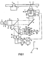
- Figure 1 schematically shows an apparatus for inscribing and/or reading a -reflecting record carrier 1.
- the round disk-shaped record carrier is shown in radial cross-section , so that the information tracks 2 extend perpendicularly to the plane of drawing, i.e. in the X direction.
- the radiation beam 7 produced by a radiation source 6, for example a gas laser or a semiconductor- diode laser, is reflected to the record carrier by a mirror 9, the beam being focused by an objective system 10 to form a radiation spot V of minimal dimensions in the plane of the information tracks 2.
- the reflecting information structure is located on the upper side of the record carrier, so that the substrate 3 functions as a protective layer.
- a modulator 13 for example an electro-optical or an acousto-optical modulator, may be arranged in the radiation path, the signal to be recorded being applied to the input terminals 13', 13" of said modulator. If the radiation source is a diode laser said laser can be modulated directly and no separate modulator 13 is needed.
- the detection system 12 may, in principle, comprise one radiation-sensitive detector, which converts the intensity modulation of the beam 7' into an electric signal.
- a write/read apparatus requires a servosystem in order to correct the position of the radiation spot relative to a track.
- a deviation of the position of the centre of the radiation spot relative to the track may for example be detected in the manner as shown in Figure 1.
- the detection system 12 comprises two detectors 12' and 12", which are arranged adjacent each other in the Y-direction, that is in the direction transverse to the track direction. The output signals of these detectors are applied to the inputs of a differential amplifier 14, on whose output a positional error signal S is available.
- This signal is applied to a controller 14, which controls an actuator 16 by means of which the objective system can be moved in the direction of the arrow 17. If the radiation spot V has shifted to the left or to the right relative to the track centre, one of the detectors 12" or 12' will receive a higher radiation intensity than the other, so that the signal S increases or decreases respectively. Consequently, the objective system is moved to the right or to the left respectively.
- a signal S 1 is obtained, which represents the information being read.
- This signal is applied to an electronic processing circuit 19, in which it is rendered suitable for reproduction by means of conventional equipment, such as a television set or audio equipment.
- FIG 1 shows an example of a focusing-error detection system.
- a semi-transparent mirror 20 a part of the reflected beam 7' is routed to a second radiation-sensitive detection system 24.
- the beam 21 is focused at a wedge 23. Said wedge splits the beam into two subbeams 21a and 21b, the intensity distribution within each of said beams being determined by the degree of focusing of the beam 7 on the information structure.
- the detection system 24 comprises four detectors 24a, 24b, 24c and 24d.
- the signals from the detectors 24a and 24d are together applied to a first input of a differential amplifier 25 and the signals from the detectors 24b and 24c to a second input of said amplifier.
- the focusing-error signal S f supplied by the differential amplifier 25 is applied to a controller 26.
- said system may be equipped with electro-magnetic actuating means, which in Figure 1 are schematically represented by the coil 27.
- the controller 26 then controls the current through said coil.
- the beam 21 is focused exactly at the top of the wedge 23 and the intensity distribution of/the respective beams 21a and 21b is then symmetrical relative to the detectors 24a, 24b and the detectors 24c, 24d respectively, the signal S fbeing zero.
- the intensity distribution within the beams 21a and 21b relative to the detectors will vary.
- the signal S f then departs from zero and the current through the coil 27 of the objective system changes.
- the position of the radiation spot in the radial direction, that is in the Y-direction can be controlled very accurately.
- This system is intended for fine control and has a small range.
- this sytem is combined with a second servosystem, which enables coarse control of the radial position of the radiation spot.
- Said second servosystem may comprise a system for controlling the position, in the Y-direction, of a carriage on which all the elements of the radiation path are arranged. It is alternatively possible that those elements to which the electrical wires should be connected, such as the radiation source and the detectors are not arranged on a carriage for coarse control.
- Such a carriage may for example only carry the objective system and the mirror 9.
- an objective system may exhibit tilting about the X-axis. In order to control such tilting, the angle of tilt should also be measured.
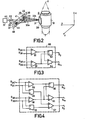
- a prism 30 is arranged, in accordance with the invention, on the objective system or on a holder for said system. Said prism forms part of a position-detection system which is shown in Figure 2.
- the objective system 10 in Figure 2 is rotated through 90 0 about the Z-axis relative to the system in Figure 1.
- the position-detection system comprises an auxiliary radiation source 32, for example a diode laser, which emits a radiation beam 33, which beam is incident on the prism 30. If the beam is incident on the refracting edge of the prism, two subbeams 33a and 33b are formed, which are reflected to thedetectors 34 and 35.
- Each of said detectors is divided into two sub-detectors 36, 37 and 38, 39 respectively, the separating lines of the subdetectors being transverse to the refracting edge 31 of the prism 30.
- the detectors may be arranged on a common support 40, in which an aperture 41 is formed for the beam 33.
- a lens 42 may be provided, which transforms the diverging beam from the source into a parallel beam or a converging beam.
- the radiation spot on the prism can be smaller, so that the sensitivity of the detection device increases.
- the radiation source is arranged on the support 40 at the location of the aperture 41.
- the centre of the radiation beam 33 is exactly incident on the refracting edge of the prism.
- the radiation spots 44 and 45 formed on the detectors 34 and 35 by the reflected beams 33a and 33b then have the same radiation energy. If the objective system is off-centre, the beam 33 will be asymmetrically incident on the prism and more radiation energy will be reflected via one of the beams 33a and 33b than via the other beam. If the signals from the detectors 36, 37, 38 and 39 are designated S36, 5 37 ,S 38 and 5 39 , the signal Sywhich represents the position of the objective system in the Y-direction will be:
- a signal S xr which is proportional to the tilting angle of the objective system about the X-axis may be represented by:
- Figure 3 shows an embodiment of an electronic circuit 50 in which the detector signals are processed to the signals S and S xr .
- the signals from the detectors 36 and 38 are applied to a first differential amplifier 51 and those from the detectors 37 and 39 to a second differential amplifier 52.
- the outputs of the differential amplifiers are connected both to the inputs of a third differential amplifier 54 and to the inputs of a summing device 53.
- On the output of the summing device 53 the position signal S is obtained and on the output of the differential amplifier 54 the tilting signal S xr .
- the signal S y may be applied to the controller 26 of Figure 1.
- the signal S xr may be applied to the electromagnetic means associated with the objective system, which means are capable of tilting said system about the X-axis.
- the means by which the objective system can be moved in the direction of the Y-axis and can be tilted about the X-axis fall beyond the scope of the present invention.
- Said means may for example be constructed as described in Netherlands Patent Application No. 770323 (PHN 8739) or Netherlands Patent Application No. 8004380 (PHN 9806), which are incorporated herein by reference.
- Both a translation and a tilted position of the object can be measured simultaneously by simple means, namely a small prism on the object, which prism hardly influences the movement of said object, a simple radiation source, in the form of, for example, a light-emitting diode (LED) or a diode laser, two detectors which are divided into two sections , and a simple electronic circuit.
- simple means namely a small prism on the object, which prism hardly influences the movement of said object
- a simple radiation source in the form of, for example, a light-emitting diode (LED) or a diode laser, two detectors which are divided into two sections , and a simple electronic circuit.
- the arrangement in accordance with Figure 2 also enables a second tilt angle to be measured, namely that about the Y-axis. Such tilting results in the radiation spots 44 and 45 both being moved upward or downward.
- the signal S which is proportional to said tilting angle is given by:
- Figure 4 shows an example of an electronic circuit in which the signals S 36 , S 37 , S 38 and S 39 are processed to the signals S , S xr and S .
- the operation of this circuit is obvious to those skilled in the art and is therefore not discussed in more detail.
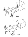
- Figure 5 shows a position-detection system by means of which the position along the X-axis, that is the direction of the radiation beam 33, and the tilt angle relative to the Z-axis of an arbitrary object 65 can be measured.
- the separating lines of the subdetectors 66, 67, 68 and 69 are now parallel to the refracting edge 31. If the object moves in the positive X-direction, that is towards the reader in Figure 5, the radiation spots 44 and 45 will both move inwards and the detectors 67 and 68 will receive more radiation than the detectors 66 and 69.
- the signal S x which represents the position along the X-axis, is:
- the signal S zr which is a measure of this tilt angle, is represented by:
- a great advantage of the position-detection device described is that the object which is measured is very lightly loaded and that said object need not be connected to the measuring arrangement via wires. For the measurement it suffices that a small prism is attached to the object, the other elements of the detection system being stationary.
- the object may also be located at a comparatively large distance from the source and the detectors, provided that a sufficiently large portion of the radiation beam 33 is incident on the prism.
- the position-detection device may for example be used with great advantage in displacement or inclination measurements or vibration tests to which objects or models which float on a fluid or which are located in a wind tunnel are subjected.
- the principal advantage of the position detection system is that by means of a simple arrangement it is, in principle, possible to simultaneously measure vibrations or displacements along two orthogonal axes and tilting about three axes of an object.
- An arrangement suitable for this purpose is shown in Figure 6. This arrangement differs from that in accordance with Figure 5 in that each of the detectors is now divided into four subdetectors 71, 72, 73, 74 and 75, 76, 77 and 78 respectively.
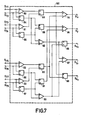
- Figure 7 shows an example of an electronic circuit for processing the detector signals into the signals S x , S y , S xr , S yr , S zr .
- This circuit which comprises a large number of subtractors and adders bearing separate reference numerals, is evident from the Figure and requires no further explanation.
- the separating lines of the subdetectors need not be disposed transversely and parallel to the refracting edge of the prism, but may alternatively be disposed at an angle of 45° to said edge.
- the radiation energy in the centre of the detectors will not change.
- the centres of the two detectors may be radiation-insensitive,so that the sensitivity of the detection device increases.
- the detectors may also be circular instead of rectangular and then for example comprise a radiation-sensitive ring, divided into segments, surrounding a radiation-insensitive centre portion.
- the detector signals in the detection devices in accordance with Figures 2, 5 and 6 are independent of displacements of the object in the Z-direction.
- a displacement in said direction may lead to increased cross-talk between translational position signals and tilt signals.
- the detection system is arranged in such a way relative to the object that the chief ray of the beam 33 is directed towards the average position of the tilting point of the object in the Z-direction.
- the apex angle ⁇ of the prism 30 may be 90 0 . If the detection device is employed for positioning objects which are comparatively heavy and/or which move with a comparatively high speed, it is desirable to have an early indication that the object is approaching the desired position, so that it can be slowed down in due time and the desired position approached with a sufficiently reduced speed. In that case a large lock-in range is required. Such a large lock-in range can be obtained by the use of a prism having a large apex angle.
- the lock-in range may be extended by a factor 1/2 ⁇ 2 , , where ⁇ is the base angle of the prism expressed in radians, under certain circumstances by increasing the apex angler for example up to 167°, and correspondingly reducing the base angle of the prism, for example to 6.5 0 .
Abstract
Description
- The invention relates to a device for detecting the translational position and the angular position of an object relative to a base, which device comprises a radiation source, a beam-splitting prism for reflecting a radiation beam emitted by the source to a radiation-sensitive detection system, which system comprises a plurality of detectors, the radiation distribution among the detectors being dependent on the position of the object relative to the radiation beam, and the outputs of the detectors being connected to an electronic circuit for generating an electric signal which provides an indication of the position of the object.
- The beam-splitting prism is defined as a prism having two inclined surfaces which enclose the refracting edge of said prism.
- United States Patent Specification 2,703,505 describes a device for aligning two parts of a machine relative to each other, a beam-splitting prism being arranged on one of said parts. Said prism receives a beam emitted by a radiation source and reflects the radiation to two radiation-sensitive detectors arranged on both sides of the prism. The output signals of the detectors are applied to an electronic circuit in the form of a Wheat- stone bridge, whose output signal is a measure of the displacement of the one machine part relative to the other in a direction transverse to the chief ray of the beam.
- In the known device the radiation-sensitive detectors, in the form of phototubes, and the prism are always arranged on the same machine part. In a first embodiment of this device the radiation source is arranged on the one part and the prism with the detectors on the other part. Hence, electrical wires need to be connected to both parts, the wires of at least one part being arranged so as to move with said part. This is obviated in a second embodiment in which the radiation source and the prism with the detectors are arranged on the same machine part. However, an additional reflector is needed on the second machine part to reflect the beam parallel to itself. Especially for detecting the position of a small and light object the use of said reflector, which is relatively heavy and large, may pose a problem.
- The known device only permits the measurement of rectilinear movements, as the case may be in two orthogonal directions.
- It is an object of the present invention to provide a device which is of simple construction and which also permits tilting of the object about one or a plurality of axes to be measured. According to the invention the device is characterized in that the beam splitting prism is mounted on the object that the radiation source and the radiation-sensitive detection system are mounted on the base, that each of the detectors is divided into two sub- detectors, that the separating lines of the subdetectors of each detector have the same orientation relative to the refracting edge of the prism, and that the outputs of the subdetectors are connected to separate inputs of the electronic circuit which supplies one translational position signal and at least one angular position signal.
- The term "position of the object" is to be understood to mean both the translational position of the object and the angular position of the object. The "translational position" of the object is referred to a rectilinear movement of the object along one axis of a triaxial coordinate system, whose centre coincides with the reference point relative to which measurement is effected. The "angular position" is referred to a tilted position of the object about one of the axas of the coordinate system.
- The invention may be employed with great advantage in all those cases where the position of an object or vibrations of an object need to be measured, where the object should not be excessively loaded, or where the object is not readily accessible or is located in a medium that should not be disturbed. The invention also enables measurements on objects which are disposed at a comparatively large distance from the observer. The device in accordance with the invention is especially suitable for measurements on objects which are free-floating or partly so, that is, objects with several degrees of freedom.
- A first embodiment of a device in accordance with the invention is characterized in that the separating lines of the sub-detectors are disposed transverse to the refracting edge of the prism, that the translational position signal provides an indication of the position of the object in a direction transverse to the refracting edge of the prism, and that the angular-position signal is a measure of the tilting angle of the object either about an axis transverse to the refracting edge and parallel to the chief ray of the beam, or about an axis transverse to the refracting edge and transverse to the chief ray of the beam. This device permits tilting of the object about two axes to be measured simultaneously.
- A second embodiment of the device in accordance with the invention is characterized in that the separating lines of the subdetectors are disposed parallel to the refracting edge of the prism, that the translational position signal represents the position of the object in the direction of the chief ray of the beam, and that the angular-position signal is a measure of the tilting angle of the object about an axis parallel to the refracting edge of the prism.
- An embodiment of the device in accordance with theinvention by means of which the position of the/object in two orthogonal directions and tilting of the:object about three orthogonal axes can be determined is characterized in that each of the detectors comprises four sub- detectors arranged in quadrants, the two orthogonal separating lines in the one detector having the same orientation as the corresponding separating lines in the other detector, and that the electronic circuit comprises five outputs.
- In order to prevent a tilted position or a displacement of the object from influencing a translational position signal and an angular position signal respectively, a preferred embodiment of the deviceiτ accordance with the invention is characterized in that the chief ray of the beam is directed at the average position of the tilting point of the object along a direction of motion of the object parallel to the refracting edge.
- Especially in the case of heavy and/or rapidly moving objects whose position and angular position should be adjusted accurately a large lock-in range of the detection device is required. A large lock-in range is obtained by means of an embodiment of the device in accordance with the invention, which is further characterized in that the apex angle of the prism is substantially greater than 90°.
- In recent years there has been much progress in the field of optical record carriers. The information in such record carriers is optically recorded and read. Such record carriers are suitable for the storage of a video program, of an audio program, but also of digital data, for example data received from and passed to a computer. In an apparatus for recording and/or reading an optical record carrier a radiation beam is focused by means of an objective system to form a very small radiation spot on the surface of the information structure. Especially in the case of digital data the radiation spot needs to be moved rapidly over the record carrier in order to enable areas to be inscribed and/or read at random. For this purpose use can be made of a coarse control and a fine control. The fine control may comprise the displacement or tilting of the objective system relative to the other elements of the optical system. For measuring the position of the objective system it is advantageous to utilize a device constructed in accordance with the invention. An apparatus for inscribing and/or reading an optical record carrier provided with a position-detection device in accordance with the invention is characterized in that the prism of the position-detection device is arranged on the objective system and that the outputs of the electronic circuit of the position-detection device are connected to control circuits which control electromagnetic actuating means for producing motion of the objective system.
- The invention will now be described in more detail with reference to the drawing. In the drawing:
- Figure 1 shows a write-read apparatus in which the objective system is provided with a position-detection prism,
- Figure 2 shows the position-detection device employed in said apparatus,
- Figures 3 and 4 show examples of an electronic circuit for processing the signals supplied by the detectors of the position-detection system,
- Figures 5 and 6 show two other embodiments of the position-detection device, and
- Figure 7 shows an example of an electronic circuit for processing the signals supplied by the detectors of the position-detection device of Figure 6.
- Figure 1 schematically shows an apparatus for inscribing and/or reading a -reflecting
record carrier 1. The round disk-shaped record carrier is shown in radial cross-section , so that theinformation tracks 2 extend perpendicularly to the plane of drawing, i.e. in the X direction. Theradiation beam 7 produced by aradiation source 6, for example a gas laser or a semiconductor- diode laser, is reflected to the record carrier by amirror 9, the beam being focused by anobjective system 10 to form a radiation spot V of minimal dimensions in the plane of theinformation tracks 2. Suitably, the reflecting information structure is located on the upper side of the record carrier, so that thesubstrate 3 functions as a protective layer. - When reading an inscribed record carrier use is made of the beam 7' which is reflected by the information structure. This beam traverses the objective system, is reflected by the
mirror 9 and is subsequently separated from thebeam 7 emitted by the source, for example with the aid of asemi-transparent morror 11, which reflects the beam 7' to a radiation-sensitive detection system 12. As the record carrier is rotated by a spindle 4 which is driven by amotor 5, the intensity of the beam 7' will vary at a high frequency, in accordance with the information stored in an information track. - When information is recorded the intensity of the
beam 7 is modulated in accordance with the information to be recorded. For this purpose amodulator 13, for example an electro-optical or an acousto-optical modulator, may be arranged in the radiation path, the signal to be recorded being applied to theinput terminals 13', 13" of said modulator. If the radiation source is a diode laser said laser can be modulated directly and noseparate modulator 13 is needed.. - For reading the information the
detection system 12 may, in principle, comprise one radiation-sensitive detector, which converts the intensity modulation of the beam 7' into an electric signal. A write/read apparatus requires a servosystem in order to correct the position of the radiation spot relative to a track. A deviation of the position of the centre of the radiation spot relative to the track may for example be detected in the manner as shown in Figure 1. There thedetection system 12 comprises twodetectors 12' and 12", which are arranged adjacent each other in the Y-direction, that is in the direction transverse to the track direction. The output signals of these detectors are applied to the inputs of adifferential amplifier 14, on whose output a positional error signal S is available. This signal is applied to acontroller 14, which controls anactuator 16 by means of which the objective system can be moved in the direction of thearrow 17. If the radiation spot V has shifted to the left or to the right relative to the track centre, one of thedetectors 12" or 12' will receive a higher radiation intensity than the other, so that the signal S increases or decreases respectively. Consequently, the objective system is moved to the right or to the left respectively. - By adding the signals from the
detectors 12' and 12" in the summing device 18 a signal S1 is obtained, which represents the information being read. This signal is applied to anelectronic processing circuit 19, in which it is rendered suitable for reproduction by means of conventional equipment, such as a television set or audio equipment. - When recording or reading is effected by means of a small radiation spot it is necessary to constantly check that the
radiation beam 7 is sharply focused in the plane of the information structure. Figure 1 shows an example of a focusing-error detection system. By means of a semi-transparent mirror 20 a part of the reflected beam 7' is routed to a second radiation-sensitive detection system 24. By means of alens 22 thebeam 21 is focused at awedge 23. Said wedge splits the beam into twosubbeams beam 7 on the information structure. Thedetection system 24 comprises fourdetectors detectors 24a and 24d are together applied to a first input of adifferential amplifier 25 and the signals from thedetectors differential amplifier 25 is applied to acontroller 26. In order to enable the objective system to be moved in the direction of the arrow 28 said system may be equipped with electro-magnetic actuating means, which in Figure 1 are schematically represented by thecoil 27. Thecontroller 26 then controls the current through said coil. If thebeam 7 is focused exactly in the plane of the information structure thebeam 21 is focused exactly at the top of thewedge 23 and the intensity distribution of/therespective beams detectors detectors 24c, 24d respectively, the signal S fbeing zero. When the focus of thebeam 7 moves, the intensity distribution within thebeams coil 27 of the objective system changes. - With the servosystem described (12', 12", 14, '15, 16) the position of the radiation spot in the radial direction, that is in the Y-direction, can be controlled very accurately. This system is intended for fine control and has a small range. In practice this sytem is combined with a second servosystem, which enables coarse control of the radial position of the radiation spot. Said second servosystem may comprise a system for controlling the position, in the Y-direction, of a carriage on which all the elements of the radiation path are arranged. It is alternatively possible that those elements to which the electrical wires should be connected, such as the radiation source and the detectors are not arranged on a carriage for coarse control. Such a carriage may for example only carry the objective system and the
mirror 9. - In a write/read apparatus in which the objective system can move relative to the other elements, it is desirable to detect the position of the objective system in the Y-direction. During writing and reading it is then possible to ascertain whether the fine control system is approaching the end of its control range, which covers for example only a few tracks, so that a signal which renders the coarse control system operative can be applied to said system. Furthermore, when the apparatus is started and the record carrier is not yet producing a signal S , it is desirable to measure the position of the objective system, so that said system can be set to its centre position. Finally, a displacement of the objective system out ot its centre position will result in a shift of the chief ray of the read beam 7' relative to the
detectors 12' and 12", which shift is independent of the position of the radiation spot V relative to the track centre. As a result of this, the radiation spot may then be controlled in such a way that the centre of the radiation spot no longer coincides with the track centre. In order to eliminate the influence of the position of the objective system on the signal S it is also desirable to detect the position of said system. - Moreover, an objective system may exhibit tilting about the X-axis. In order to control such tilting, the angle of tilt should also be measured.
- In, for example, NetherlandsPatent Application No. 77.03232 (PHN 8739) a write-read apparatus is proposed in which fine control of the radiation spot V in the Y-direction is achieved by slightly tilting the objective system about the X-axis. This tilted position should also be measured for the same three reasons as mentioned for the fine control of the radiation spot by means of a displacement of the objective system.
- For simultaneous measurement of the tilt and displacement of the objective system, a
prism 30 is arranged, in accordance with the invention, on the objective system or on a holder for said system. Said prism forms part of a position-detection system which is shown in Figure 2. Theobjective system 10 in Figure 2 is rotated through 900 about the Z-axis relative to the system in Figure 1. The position-detection system comprises anauxiliary radiation source 32, for example a diode laser, which emits aradiation beam 33, which beam is incident on theprism 30. If the beam is incident on the refracting edge of the prism, twosubbeams sub-detectors edge 31 of theprism 30. The detectors may be arranged on acommon support 40, in which anaperture 41 is formed for thebeam 33. If desired, alens 42 may be provided, which transforms the diverging beam from the source into a parallel beam or a converging beam. In the last-mentioned case the radiation spot on the prism can be smaller, so that the sensitivity of the detection device increases. Suitably, the radiation source is arranged on thesupport 40 at the location of theaperture 41. - Care is taken that when the objective system occupies its centre position, along the Y-axis, the centre of the
radiation beam 33 is exactly incident on the refracting edge of the prism. The radiation spots 44 and 45 formed on thedetectors beams beam 33 will be asymmetrically incident on the prism and more radiation energy will be reflected via one of thebeams detectors 
- If the detectors are correctly aligned relative to the
radiation source 32 and if the refractingedge 31 of theprism 30 is parallel to the Z axis, theradiation spot respective detectors detectors 38 and 39. If the objective system, and thus theprism 30, is now tilted about the X axis, one of the radiation spots 44 and 45, will move upward and the other downward. It will be appreciated that a signal Sxr, which is proportional to the tilting angle of the objective system about the X-axis may be represented by:
- Figure 3 shows an embodiment of an
electronic circuit 50 in which the detector signals are processed to the signals S and Sxr. The signals from thedetectors 36 and 38 are applied to a firstdifferential amplifier 51 and those from thedetectors differential amplifier 52. The outputs of the differential amplifiers are connected both to the inputs of a thirddifferential amplifier 54 and to the inputs of a summingdevice 53. On the output of the summingdevice 53 the position signal S is obtained and on the output of thedifferential amplifier 54 the tilting signal Sxr. These signals are used for correcting the objective system. - As an example, the signal Sy may be applied to the
controller 26 of Figure 1. The signal Sxr may be applied to the electromagnetic means associated with the objective system, which means are capable of tilting said system about the X-axis. The means by which the objective system can be moved in the direction of the Y-axis and can be tilted about the X-axis fall beyond the scope of the present invention. Said means may for example be constructed as described in Netherlands Patent Application No. 770323 (PHN 8739) or Netherlands Patent Application No. 8004380 (PHN 9806), which are incorporated herein by reference. - Both a translation and a tilted position of the object can be measured simultaneously by simple means, namely a small prism on the object, which prism hardly influences the movement of said object, a simple radiation source, in the form of, for example, a light-emitting diode (LED) or a diode laser, two detectors which are divided into two sections , and a simple electronic circuit.
- The arrangement in accordance with Figure 2 also enables a second tilt angle to be measured, namely that about the Y-axis. Such tilting results in the radiation spots 44 and 45 both being moved upward or downward. The signal S , which is proportional to said tilting angle is given by:

- Figure 4 shows an example of an electronic circuit in which the signals S36, S37, S38 and S39 are processed to the signals S , Sxr and S . The operation of this circuit is obvious to those skilled in the art and is therefore not discussed in more detail.
- Figure 5 shows a position-detection system by means of which the position along the X-axis, that is the direction of the
radiation beam 33, and the tilt angle relative to the Z-axis of anarbitrary object 65 can be measured. The separating lines of thesubdetectors edge 31. If the object moves in the positive X-direction, that is towards the reader in Figure 5, the radiation spots 44 and 45 will both move inwards and thedetectors detectors 
- If the object is tilted about the Z-axis, the radiation spots 44 and 45 both move in the same Y-direction. The signal Szr, which is a measure of this tilt angle, is represented by:

- In order to derive the signals Sx and Szr from the detector signals a circuit arrangement in accordance with Figure 3 may be used, the terminals to which the signals S36, S38, S37 and S39 were applied now respectively receiving the signals S66, S67, S68 and S69. The signals Szr and Sx are then obtained on the output terminals of the summing
device 53 and thedifferential amplifier 54 respectively. - A great advantage of the position-detection device described is that the object which is measured is very lightly loaded and that said object need not be connected to the measuring arrangement via wires. For the measurement it suffices that a small prism is attached to the object, the other elements of the detection system being stationary. The object may also be located at a comparatively large distance from the source and the detectors, provided that a sufficiently large portion of the
radiation beam 33 is incident on the prism. The position-detection device may for example be used with great advantage in displacement or inclination measurements or vibration tests to which objects or models which float on a fluid or which are located in a wind tunnel are subjected. - The principal advantage of the position detection system is that by means of a simple arrangement it is, in principle, possible to simultaneously measure vibrations or displacements along two orthogonal axes and tilting about three axes of an object. An arrangement suitable for this purpose is shown in Figure 6. This arrangement differs from that in accordance with Figure 5 in that each of the detectors is now divided into four
subdetectors 


- Figure 7 shows an example of an electronic circuit for processing the detector signals into the signals Sx, Sy, Sxr, Syr, Szr. The operation of this circuit, which comprises a large number of subtractors and adders bearing separate reference numerals, is evident from the Figure and requires no further explanation.
- The separating lines of the subdetectors need not be disposed transversely and parallel to the refracting edge of the prism, but may alternatively be disposed at an angle of 45° to said edge. In the case of small displacements or tilt angles of the object, the radiation energy in the centre of the detectors will not change.In those cases the centres of the two detectors may be radiation-insensitive,so that the sensitivity of the detection device increases. The detectors may also be circular instead of rectangular and then for example comprise a radiation-sensitive ring, divided into segments, surrounding a radiation-insensitive centre portion.
- The detector signals in the detection devices in accordance with Figures 2, 5 and 6 are independent of displacements of the object in the Z-direction. However, a displacement in said direction may lead to increased cross-talk between translational position signals and tilt signals. Suitably, therefore, the detection system is arranged in such a way relative to the object that the chief ray of the
beam 33 is directed towards the average position of the tilting point of the object in the Z-direction. - In principle, the apex angle α of the
prism 30 may be 900. If the detection device is employed for positioning objects which are comparatively heavy and/or which move with a comparatively high speed, it is desirable to have an early indication that the object is approaching the desired position, so that it can be slowed down in due time and the desired position approached with a sufficiently reduced speed. In that case a large lock-in range is required. Such a large lock-in range can be obtained by the use of a prism having a large apex angle. For such a prism, or wedge, a displacement of the prism relative to theincident radiation beam 33 results in a substantially smaller shift of the reflectedsubbeams detectors factor 1/2 α2, , where α is the base angle of the prism expressed in radians, under certain circumstances by increasing the apex angler for example up to 167°, and correspondingly reducing the base angle of the prism, for example to 6.50.
Claims (7)
- J A device for detecting the translational position and the angular position of an object relative to a base, comprising a radiation source, a beam-splitting prism for reflecting a radiation beam emitted by the source to a radiation-sensitive detection system, which system comprises a plurality of detectors, the radiation distribution among the detectors being dependent on the position of the object relative to the radiation beam, and the outputs of the detectors being connected to an electronic circuit for generating an electric signal which provides an indication of the position of the object, characterized in that the beam-splitting prism is mounted on the object, that the radiation source and the radiation-sensitive detection system are mounted on the base, that each of the detectors is divided into two subdetectors, that the separating lines of the sub-detectors of each detector have the same orientation relative to the refracting edge of/the prism, and that the outputs of the subdetectors are connected to separate inputs of the electronic circuit which supplies one translational . position signal and at least one angular-position signal.
- 2. A device as claimed in Claim 1, characterized in that the separating lines of the subdetectors are disposed transverse to the refracting edge of the prism, that the translational position signal provides an indication of the position of the object in a direction transverse to the refracting edge of the prism, and that the angular-position signal is a measure of the tilting angle of the object either about an axis transverse to the refracting edge and parallel to the chief ray of the beam, or about an axis transverse to the refracting edge and transverse to the chief ray of the beam.
- 3. A device as claimed in Claim 1, characterized in that the separating lines of the subdetectors are disposed parallel to the refracting edge of the prism, that the translational position signal represents the position of the object in the direction of the chief ray of the beam and that the angular-position signal is a measure of the tilting angle of the object about an axis parallel to the refracting edge of the prism.
- 4. A device as claimed in Claim 1, characterized in that each of the detectors comprises four subdetectors arranged in quadrants, the two orthogonal separating lines in the one detector having the same orientation as the corresponding separating lines in the other detector, and that the electronic circuit comprises five outputs for supplying two signals which are a measure of the translational position of the object in two orthogonal directions transverse to the refracting edge of the prism and three signals which are a measure.of tilting angles of the object about three orthogonal axes.
- 5. A device as claimed in Claim 1, 2, 3 or 4, characterized in that the chief ray of the beam is directed at the average position of the tilting point of the object along a direction of motion of the object parallel to the refracting edge of the prism.
- 6. A device as claimed in Claim 1, 2, 3, 4 or 5, characterized in that the apex angle of the prism is substantially greater than 90°.
- 7. An apparatus for optically reading and/or recording a trackwise arranged information structure, which apparatus comprises a radiation source, an objective system for focusing the radiation beam produced by the radiation source to form a radiation spot in the plane of the information structure, and a position-detection device as claimed in any one of the preceding Claims, characterized in that the prism of the position-detection device is arranged on the objective system and that the outputs of the electronic circuit of the position-detection device are connected to control circuits which control electromagnetic actuating means for producing motion of the objective system.
Priority Applications (1)
| Application Number | Priority Date | Filing Date | Title |
|---|---|---|---|
| AT82200364T ATE14930T1 (en) | 1981-04-03 | 1982-03-24 | DEVICE FOR DETECTING THE POSITION OF AN OBJECT. |
Applications Claiming Priority (2)
| Application Number | Priority Date | Filing Date | Title |
|---|---|---|---|
| NL8101669A NL8101669A (en) | 1981-04-03 | 1981-04-03 | DEVICE FOR DETECTING THE POSITION OF AN OBJECT. |
| NL8101669 | 1981-04-03 |
Publications (2)
| Publication Number | Publication Date |
|---|---|
| EP0063830A1 true EP0063830A1 (en) | 1982-11-03 |
| EP0063830B1 EP0063830B1 (en) | 1985-08-14 |
Family
ID=19837294
Family Applications (1)
| Application Number | Title | Priority Date | Filing Date |
|---|---|---|---|
| EP82200364A Expired EP0063830B1 (en) | 1981-04-03 | 1982-03-24 | Device for detecting the position of an object |
Country Status (9)
| Country | Link |
|---|---|
| US (1) | US4425043A (en) |
| EP (1) | EP0063830B1 (en) |
| JP (1) | JPS57178101A (en) |
| AT (1) | ATE14930T1 (en) |
| AU (1) | AU547436B2 (en) |
| CA (1) | CA1194178A (en) |
| DE (1) | DE3265346D1 (en) |
| ES (1) | ES511051A0 (en) |
| NL (1) | NL8101669A (en) |
Cited By (8)
| Publication number | Priority date | Publication date | Assignee | Title |
|---|---|---|---|---|
| EP0116467A2 (en) * | 1983-02-10 | 1984-08-22 | Sony Corporation | Optical disc players |
| EP0145787A1 (en) * | 1983-02-22 | 1985-06-26 | Matsushita Electric Industrial Co., Ltd. | Apparatus for controlling tracking of recorded disc reproduction device |
| EP0152487A1 (en) * | 1983-05-17 | 1985-08-28 | Matsushita Electric Industrial Co., Ltd. | Position-detecting apparatus |
| EP0206396A1 (en) * | 1985-06-10 | 1986-12-30 | Koninklijke Philips Electronics N.V. | Optical scanning unit comprising a translational-position and angular-position detection system for an electro-magnetically suspended objective |
| EP0361330A2 (en) * | 1988-09-26 | 1990-04-04 | Alliant Techsystems Inc. | Object motion sensing and measuring apparatus |
| EP0414559A2 (en) * | 1989-08-24 | 1991-02-27 | Optrocom Systems Limited | Optical angle measuring apparatus |
| EP0662626A1 (en) * | 1993-12-28 | 1995-07-12 | Canon Kabushiki Kaisha | Angular deviation detection apparatus |
| GB2327123B (en) * | 1996-02-13 | 2000-09-13 | Amada Metrecs Co | Angle detection method for bending machines, and angle detection apparatus and angle sensor thereof |
Families Citing this family (58)
| Publication number | Priority date | Publication date | Assignee | Title |
|---|---|---|---|---|
| KR880000999B1 (en) * | 1981-11-25 | 1988-06-10 | 미쓰다 가쓰시게 | Optical memory apparatus |
| US4576481A (en) * | 1982-12-13 | 1986-03-18 | Position Orientation Systems, Ltd. | Passive optical position measurement system |
| AU575332B2 (en) * | 1983-07-29 | 1988-07-28 | Sony Corporation | Optical disk pick-up |
| US4590594A (en) * | 1983-11-23 | 1986-05-20 | Rca Corporation | Side-spot focus apparatus for optical disc recording and/or playback system |
| JPS60170721A (en) * | 1984-02-16 | 1985-09-04 | Tdk Corp | Linear encoder |
| JPS60211302A (en) * | 1984-04-06 | 1985-10-23 | Toshiba Corp | Inclination measuring instrument |
| US4677605A (en) * | 1984-07-06 | 1987-06-30 | Storage Technology Partners Ii | Focus acquisition and maintenance for optical disk system |
| JPS6155153A (en) * | 1984-08-27 | 1986-03-19 | Mitsui Toatsu Chem Inc | Thermosetting resin molding material |
| JPS6155154A (en) * | 1984-08-27 | 1986-03-19 | Mitsui Toatsu Chem Inc | Thermosetting resin molding material for extrusion |
| JPS6155150A (en) * | 1984-08-27 | 1986-03-19 | Mitsui Toatsu Chem Inc | Thermosetting resin molding material |
| JPS6155151A (en) * | 1984-08-27 | 1986-03-19 | Mitsui Toatsu Chem Inc | Thermosetting resin molding material |
| US4615615A (en) * | 1984-09-27 | 1986-10-07 | Flexible Manufacturing Systems, Inc. | Laser positioning system |
| JPH0617828B2 (en) * | 1984-10-30 | 1994-03-09 | ミノルタカメラ株式会社 | Radiation thermometer optics |
| JPS61158044A (en) * | 1984-12-28 | 1986-07-17 | Nec Home Electronics Ltd | Tracking error detecting device |
| JPS61158043A (en) * | 1984-12-28 | 1986-07-17 | Nec Home Electronics Ltd | Tracking error detecting device |
| US5416755A (en) * | 1985-02-28 | 1995-05-16 | Canon Kabushiki Kaisha | Optical pickup using split beams impinging on different photo-detector areas |
| US5559322A (en) * | 1985-03-11 | 1996-09-24 | Trw Inc. | Imaging optical tracker |
| JPS61276137A (en) * | 1985-05-30 | 1986-12-06 | Fujitsu Ltd | Optical head actuator |
| JPH0781850B2 (en) * | 1985-09-19 | 1995-09-06 | 理化学研究所 | Optical distance inclination information acquisition device |
| JPH0715367B2 (en) * | 1985-10-15 | 1995-02-22 | キヤノン株式会社 | Displacement / rotation detection method and attitude control device |
| DE3640660A1 (en) * | 1985-11-28 | 1987-06-04 | Toshiba Kk | DEVICE FOR DETERMINING THE POSITION OF A LENS |
| NL8600168A (en) * | 1986-01-27 | 1987-08-17 | Philips Nv | OPTICAL PROBE. |
| IT8747637A0 (en) * | 1986-02-19 | 1987-02-12 | Sagem | OPTICAL DEVICE FOR REMOTE MEASUREMENT OF VARIATIONS IN THE ORIENTATION OF AN OBJECT |
| US4956833A (en) * | 1986-03-31 | 1990-09-11 | Asahi Kogaku Kogyo Kabushiki Kaisha | Objective driving device for an optical disk apparatus |
| JPH01503560A (en) * | 1986-08-13 | 1989-11-30 | ザ ブロークン ヒル プロプライエタリー カンパニー リミテツド | Method and device for measuring dimensions of articles |
| JPH0812044B2 (en) * | 1986-09-10 | 1996-02-07 | 株式会社東海理化電機製作所 | Tape edge coordinate measuring method and device |
| DE3643723A1 (en) * | 1986-12-20 | 1988-07-07 | Leitz Ernst Gmbh | Method and arrangement for optical measurement of the rolling angle of a moving machine part |
| DE3740227C2 (en) * | 1987-11-27 | 1994-03-24 | Schenck Ag Carl | Method and device for measuring deformations on samples or test specimens in testing machines |
| JP2635608B2 (en) * | 1987-08-29 | 1997-07-30 | 株式会社東芝 | Optical information storage medium inspection device |
| JPS6488302A (en) * | 1987-09-30 | 1989-04-03 | Omron Tateisi Electronics Co | Position detecting device |
| US4907879A (en) * | 1988-01-15 | 1990-03-13 | Webb James B | Remote controlled land surveying assistance device for path response alignment to beam energy |
| JPH01201831A (en) * | 1988-02-05 | 1989-08-14 | Olympus Optical Co Ltd | Optical information recording and reproducing device |
| JPH01165416U (en) * | 1988-05-12 | 1989-11-20 | ||
| US5090002A (en) * | 1989-03-07 | 1992-02-18 | International Business Machines Corporation | Positioning systems employing velocity and position control loops with position control loop having an extended range |
| US5265079A (en) | 1991-02-15 | 1993-11-23 | Applied Magnetics Corporation | Seek actuator for optical recording |
| US6141300A (en) * | 1989-06-20 | 2000-10-31 | Discovision Associates | Optical actuator including lens assembly with optical axis having symmetric suspensory forces acting thereon and optical disc system including same |
| JPH03269311A (en) * | 1990-03-20 | 1991-11-29 | Copal Electron Co Ltd | Optical beam position detector |
| NL9001253A (en) * | 1990-06-01 | 1992-01-02 | Philips Nv | DEVICE FOR OPTICALLY DETERMINING THE POSITION AND POSITION OF AN OBJECT AND OPTICAL ENTRY AND / OR DISPLAY DEVICE EQUIPPED WITH SUCH A DEVICE. |
| JPH0827962B2 (en) * | 1990-06-27 | 1996-03-21 | パイオニア株式会社 | Optical pickup |
| DE69130147T2 (en) * | 1990-10-03 | 1999-04-01 | Aisin Seiki | Automatic control system for lateral guidance |
| US5390118A (en) * | 1990-10-03 | 1995-02-14 | Aisin Seiki Kabushiki Kaisha | Automatic lateral guidance control system |
| US5202742A (en) * | 1990-10-03 | 1993-04-13 | Aisin Seiki Kabushiki Kaisha | Laser radar for a vehicle lateral guidance system |
| JP2629456B2 (en) * | 1991-01-17 | 1997-07-09 | 三菱電機株式会社 | Objective lens position detector |
| JP2629457B2 (en) * | 1991-01-17 | 1997-07-09 | 三菱電機株式会社 | Objective lens position detector |
| US6069857A (en) * | 1991-02-15 | 2000-05-30 | Discovision Associates | Optical disc system having improved circuitry for performing blank sector check on readable disc |
| US6236625B1 (en) | 1991-02-15 | 2001-05-22 | Discovision Associates | Optical disc system having current monitoring circuit with controller for laser driver and method for operating same |
| US5677899A (en) * | 1991-02-15 | 1997-10-14 | Discovision Associates | Method for moving carriage assembly from initial position to target position relative to storage medium |
| US5729511A (en) | 1991-02-15 | 1998-03-17 | Discovision Associates | Optical disc system having servo motor and servo error detection assembly operated relative to monitored quad sum signal |
| US5214278A (en) * | 1991-11-01 | 1993-05-25 | Combustion Engineering, Inc. | Apparatus for monitoring speed and lateral position of a rotating shaft having reflective surfaces |
| US5416756A (en) * | 1991-11-07 | 1995-05-16 | Mitsubishi Denki Kabushiki Kaisha | Lens actuating system with improved frequency response for optical disk drive |
| US5220397A (en) * | 1992-03-25 | 1993-06-15 | Peisen Huang | Method and apparatus for angle measurement based on the internal reflection effect |
| US6091684A (en) * | 1995-01-25 | 2000-07-18 | Discovision Associates | Optical disc system and method for changing the rotational rate of an information storage medium |
| US6434087B1 (en) | 1995-01-25 | 2002-08-13 | Discovision Associates | Optical disc system and method for controlling bias coil and light source to process information on a storage medium |
| US5784168A (en) * | 1995-07-03 | 1998-07-21 | U.S. Philips Corporation | Position detection system for an object with at least five degrees of freedom |
| JP2885338B2 (en) * | 1996-05-07 | 1999-04-19 | オリンパス光学工業株式会社 | Optical pickup |
| US6160774A (en) * | 1997-09-22 | 2000-12-12 | Seagate Technology Llc | Position sensor for tracking system for optical data storage |
| US6466525B1 (en) | 1999-03-09 | 2002-10-15 | Seagate Technology Llc | Optical disc data storage system |
| GB2465565B (en) * | 2008-11-19 | 2013-08-07 | Servomex Group Ltd | Compact paramagnetic oxygen sensor |
Citations (5)
| Publication number | Priority date | Publication date | Assignee | Title |
|---|---|---|---|---|
| US3582214A (en) * | 1969-10-31 | 1971-06-01 | James W Loomis | Tool alignment apparatus and method |
| FR2068070A5 (en) * | 1969-11-27 | 1971-08-20 | Matare Herbert | |
| US3723013A (en) * | 1970-10-23 | 1973-03-27 | Atomic Energy Commission | Alignment system |
| FR2226644A1 (en) * | 1973-04-18 | 1974-11-15 | Barbier Benard Turenne Anc Ets | Optical measurement of displacement - uses electronic circuits eliminating lighting effects enabling use of stroboscopic lighting |
| FR2410249A1 (en) * | 1977-11-24 | 1979-06-22 | Zeiss Jena Veb Carl | DEVICE FOR SIMULTANEOUSLY CARRYING OUT ALIGNMENT AND STEERING MEASUREMENTS |
Family Cites Families (1)
| Publication number | Priority date | Publication date | Assignee | Title |
|---|---|---|---|---|
| NL7703232A (en) * | 1977-03-25 | 1978-09-27 | Philips Nv | OPTICAL SCANNER. |
-
1981
- 1981-04-03 NL NL8101669A patent/NL8101669A/en not_active Application Discontinuation
- 1981-07-13 US US06/282,626 patent/US4425043A/en not_active Expired - Fee Related
-
1982
- 1982-03-24 EP EP82200364A patent/EP0063830B1/en not_active Expired
- 1982-03-24 DE DE8282200364T patent/DE3265346D1/en not_active Expired
- 1982-03-24 AT AT82200364T patent/ATE14930T1/en not_active IP Right Cessation
- 1982-03-31 CA CA000400099A patent/CA1194178A/en not_active Expired
- 1982-04-01 AU AU82260/82A patent/AU547436B2/en not_active Ceased
- 1982-04-01 ES ES511051A patent/ES511051A0/en active Granted
- 1982-04-02 JP JP57053991A patent/JPS57178101A/en active Granted
Patent Citations (5)
| Publication number | Priority date | Publication date | Assignee | Title |
|---|---|---|---|---|
| US3582214A (en) * | 1969-10-31 | 1971-06-01 | James W Loomis | Tool alignment apparatus and method |
| FR2068070A5 (en) * | 1969-11-27 | 1971-08-20 | Matare Herbert | |
| US3723013A (en) * | 1970-10-23 | 1973-03-27 | Atomic Energy Commission | Alignment system |
| FR2226644A1 (en) * | 1973-04-18 | 1974-11-15 | Barbier Benard Turenne Anc Ets | Optical measurement of displacement - uses electronic circuits eliminating lighting effects enabling use of stroboscopic lighting |
| FR2410249A1 (en) * | 1977-11-24 | 1979-06-22 | Zeiss Jena Veb Carl | DEVICE FOR SIMULTANEOUSLY CARRYING OUT ALIGNMENT AND STEERING MEASUREMENTS |
Cited By (17)
| Publication number | Priority date | Publication date | Assignee | Title |
|---|---|---|---|---|
| EP0116467A2 (en) * | 1983-02-10 | 1984-08-22 | Sony Corporation | Optical disc players |
| EP0116467A3 (en) * | 1983-02-10 | 1987-06-24 | Sony Corporation | Optical disc players |
| EP0145787A1 (en) * | 1983-02-22 | 1985-06-26 | Matsushita Electric Industrial Co., Ltd. | Apparatus for controlling tracking of recorded disc reproduction device |
| EP0145787A4 (en) * | 1983-02-22 | 1987-02-12 | Matsushita Electric Ind Co Ltd | Apparatus for controlling tracking of recorded disc reproduction device. |
| US4799206A (en) * | 1983-02-22 | 1989-01-17 | Matsushita Electric Industrial Co., Ltd. | Tracking control apparatus for recording disc reproducing apparatus |
| EP0152487A1 (en) * | 1983-05-17 | 1985-08-28 | Matsushita Electric Industrial Co., Ltd. | Position-detecting apparatus |
| EP0152487A4 (en) * | 1983-05-17 | 1990-02-05 | Matsushita Electric Ind Co Ltd | Position-detecting apparatus. |
| EP0206396A1 (en) * | 1985-06-10 | 1986-12-30 | Koninklijke Philips Electronics N.V. | Optical scanning unit comprising a translational-position and angular-position detection system for an electro-magnetically suspended objective |
| EP0361330A2 (en) * | 1988-09-26 | 1990-04-04 | Alliant Techsystems Inc. | Object motion sensing and measuring apparatus |
| EP0361330A3 (en) * | 1988-09-26 | 1992-06-03 | Alliant Techsystems Inc. | Object motion sensing and measuring apparatus |
| EP0414559A2 (en) * | 1989-08-24 | 1991-02-27 | Optrocom Systems Limited | Optical angle measuring apparatus |
| EP0414559A3 (en) * | 1989-08-24 | 1991-10-02 | Optrocom Systems Limited | Optical angle measuring apparatus |
| US5689369A (en) * | 1993-12-08 | 1997-11-18 | Canon Kabushiki Kaisha | Angular deviation detection apparatus |
| EP0662626A1 (en) * | 1993-12-28 | 1995-07-12 | Canon Kabushiki Kaisha | Angular deviation detection apparatus |
| GB2327123B (en) * | 1996-02-13 | 2000-09-13 | Amada Metrecs Co | Angle detection method for bending machines, and angle detection apparatus and angle sensor thereof |
| US6268912B1 (en) | 1996-02-13 | 2001-07-31 | Amada Electronics Company, Ltd. | Angle detection method for bending machine, angle detection apparatus and angle sensor |
| US6480269B2 (en) | 1996-02-13 | 2002-11-12 | Amada Electronics Company, Ltd. | Angle detection method for bending machine, angle detection apparatus and angle sensor |
Also Published As
| Publication number | Publication date |
|---|---|
| EP0063830B1 (en) | 1985-08-14 |
| ES8307404A1 (en) | 1983-06-16 |
| AU8226082A (en) | 1982-10-07 |
| CA1194178A (en) | 1985-09-24 |
| JPS57178101A (en) | 1982-11-02 |
| ES511051A0 (en) | 1983-06-16 |
| US4425043A (en) | 1984-01-10 |
| ATE14930T1 (en) | 1985-08-15 |
| DE3265346D1 (en) | 1985-09-19 |
| AU547436B2 (en) | 1985-10-17 |
| JPH0141203B2 (en) | 1989-09-04 |
| NL8101669A (en) | 1982-11-01 |
Similar Documents
| Publication | Publication Date | Title |
|---|---|---|
| EP0063830B1 (en) | Device for detecting the position of an object | |
| EP0084727B1 (en) | Galvo position sensor for improved track selection in optical data | |
| US4023033A (en) | Optical focussing device | |
| EP0084728B1 (en) | Technique for monitoring galvo angle | |
| US4782474A (en) | Tracking servo system for controllably projecting an optical beam on an optical disk | |
| US4817074A (en) | Method and apparatus for detecting the focusing state and positioning accuracy of a light beam directed onto an optical disk tracking guide in an optical recording system | |
| JPS6048949B2 (en) | A device that reads information using a light beam | |
| GB2086092A (en) | Tracking apparatus for an optically readable record | |
| US5195081A (en) | Optical apparatus for effecting recording and/or reproducing of information on/from and optical information recording medium | |
| US5198916A (en) | Optical pickup | |
| US5301175A (en) | Optical head apparatus for maintaining a constant angle between an optical axis of an object lens and the surface of a storage medium | |
| JPH0353702B2 (en) | ||
| US4900910A (en) | System for detecting the position of an objective lens | |
| US5105411A (en) | Apparatus for detecting and correcting focusing and tracking errors | |
| US5910936A (en) | Measuring and compensating for warp in an optical recording disk | |
| MY104267A (en) | Optical pick-up devices | |
| US5107102A (en) | Arrangement for detecting a signal for effecting a focus control of an optical head | |
| US5787062A (en) | Disc-thickness-and-warp detecting apparatus | |
| JPS62200541A (en) | Light emitting quantity controller | |
| JP2606492B2 (en) | Optical recording / reproducing device | |
| JP2004111032A (en) | Actuator and optical pickup employing the same | |
| JPS58196629A (en) | Optical recording and reproducing device | |
| JP2003022551A (en) | Optical head and optical device | |
| JPH01144229A (en) | Optical head | |
| JPS61243951A (en) | Optical head |
Legal Events
| Date | Code | Title | Description |
|---|---|---|---|
| PUAI | Public reference made under article 153(3) epc to a published international application that has entered the european phase |
Free format text: ORIGINAL CODE: 0009012 |
|
| 17P | Request for examination filed |
Effective date: 19820324 |
|
| AK | Designated contracting states |
Designated state(s): AT BE DE FR GB IT NL SE |
|
| ITF | It: translation for a ep patent filed |
Owner name: ING. C. GREGORJ S.P.A. |
|
| GRAA | (expected) grant |
Free format text: ORIGINAL CODE: 0009210 |
|
| AK | Designated contracting states |
Designated state(s): AT BE DE FR GB IT NL SE |
|
| REF | Corresponds to: |
Ref document number: 14930 Country of ref document: AT Date of ref document: 19850815 Kind code of ref document: T |
|
| REF | Corresponds to: |
Ref document number: 3265346 Country of ref document: DE Date of ref document: 19850919 |
|
| ET | Fr: translation filed | ||
| PLBE | No opposition filed within time limit |
Free format text: ORIGINAL CODE: 0009261 |
|
| STAA | Information on the status of an ep patent application or granted ep patent |
Free format text: STATUS: NO OPPOSITION FILED WITHIN TIME LIMIT |
|
| 26N | No opposition filed | ||
| PGFP | Annual fee paid to national office [announced via postgrant information from national office to epo] |
Ref country code: AT Payment date: 19870312 Year of fee payment: 6 |
|
| PGFP | Annual fee paid to national office [announced via postgrant information from national office to epo] |
Ref country code: NL Payment date: 19870331 Year of fee payment: 6 |
|
| PG25 | Lapsed in a contracting state [announced via postgrant information from national office to epo] |
Ref country code: AT Effective date: 19890324 |
|
| PG25 | Lapsed in a contracting state [announced via postgrant information from national office to epo] |
Ref country code: BE Effective date: 19890331 |
|
| BERE | Be: lapsed |
Owner name: N.V. PHILIPS' GLOEILAMPENFABRIEKEN Effective date: 19890331 |
|
| PG25 | Lapsed in a contracting state [announced via postgrant information from national office to epo] |
Ref country code: NL Effective date: 19891001 |
|
| NLV4 | Nl: lapsed or anulled due to non-payment of the annual fee | ||
| PGFP | Annual fee paid to national office [announced via postgrant information from national office to epo] |
Ref country code: GB Payment date: 19900228 Year of fee payment: 9 |
|
| PGFP | Annual fee paid to national office [announced via postgrant information from national office to epo] |
Ref country code: FR Payment date: 19900320 Year of fee payment: 9 |
|
| PGFP | Annual fee paid to national office [announced via postgrant information from national office to epo] |
Ref country code: SE Payment date: 19900327 Year of fee payment: 9 |
|
| ITTA | It: last paid annual fee | ||
| PGFP | Annual fee paid to national office [announced via postgrant information from national office to epo] |
Ref country code: DE Payment date: 19900523 Year of fee payment: 9 |
|
| PG25 | Lapsed in a contracting state [announced via postgrant information from national office to epo] |
Ref country code: GB Effective date: 19910324 |
|
| PG25 | Lapsed in a contracting state [announced via postgrant information from national office to epo] |
Ref country code: SE Effective date: 19910325 |
|
| GBPC | Gb: european patent ceased through non-payment of renewal fee | ||
| PG25 | Lapsed in a contracting state [announced via postgrant information from national office to epo] |
Ref country code: FR Effective date: 19911129 |
|
| PG25 | Lapsed in a contracting state [announced via postgrant information from national office to epo] |
Ref country code: DE Effective date: 19920101 |
|
| REG | Reference to a national code |
Ref country code: FR Ref legal event code: ST |
|
| EUG | Se: european patent has lapsed |
Ref document number: 82200364.6 Effective date: 19911009 |