EP0064548B1 - Drops sensing unit and associated drip chamber for iv fluid administration - Google Patents
Drops sensing unit and associated drip chamber for iv fluid administration Download PDFInfo
- Publication number
- EP0064548B1 EP0064548B1 EP82900057A EP82900057A EP0064548B1 EP 0064548 B1 EP0064548 B1 EP 0064548B1 EP 82900057 A EP82900057 A EP 82900057A EP 82900057 A EP82900057 A EP 82900057A EP 0064548 B1 EP0064548 B1 EP 0064548B1
- Authority
- EP
- European Patent Office
- Prior art keywords
- drip chamber
- sensing unit
- drop
- drop sensor
- sensor
- Prior art date
- Legal status (The legal status is an assumption and is not a legal conclusion. Google has not performed a legal analysis and makes no representation as to the accuracy of the status listed.)
- Expired
Links
Images

Classifications
-
- A—HUMAN NECESSITIES
- A61—MEDICAL OR VETERINARY SCIENCE; HYGIENE
- A61M—DEVICES FOR INTRODUCING MEDIA INTO, OR ONTO, THE BODY; DEVICES FOR TRANSDUCING BODY MEDIA OR FOR TAKING MEDIA FROM THE BODY; DEVICES FOR PRODUCING OR ENDING SLEEP OR STUPOR
- A61M5/00—Devices for bringing media into the body in a subcutaneous, intra-vascular or intramuscular way; Accessories therefor, e.g. filling or cleaning devices, arm-rests
- A61M5/14—Infusion devices, e.g. infusing by gravity; Blood infusion; Accessories therefor
- A61M5/168—Means for controlling media flow to the body or for metering media to the body, e.g. drip meters, counters ; Monitoring media flow to the body
- A61M5/16886—Means for controlling media flow to the body or for metering media to the body, e.g. drip meters, counters ; Monitoring media flow to the body for measuring fluid flow rate, i.e. flowmeters
- A61M5/1689—Drip counters
-
- Y—GENERAL TAGGING OF NEW TECHNOLOGICAL DEVELOPMENTS; GENERAL TAGGING OF CROSS-SECTIONAL TECHNOLOGIES SPANNING OVER SEVERAL SECTIONS OF THE IPC; TECHNICAL SUBJECTS COVERED BY FORMER USPC CROSS-REFERENCE ART COLLECTIONS [XRACs] AND DIGESTS
- Y10—TECHNICAL SUBJECTS COVERED BY FORMER USPC
- Y10S—TECHNICAL SUBJECTS COVERED BY FORMER USPC CROSS-REFERENCE ART COLLECTIONS [XRACs] AND DIGESTS
- Y10S128/00—Surgery
- Y10S128/13—Infusion monitoring
Definitions
- IV administration parenteral fluid administration
- IV drop sensing unit and dedicated drip chamber for use in an IV fluid administration system whereby installation, retention and removal are enhanced and aid is afforded in preventing use of chambers differing from the dedicated design.
- IV fluid administration has conventionally involved use of a disposable fluid administration set with an elongated drip chamber. Discrete fluid drops fall from a drop former to a reservoir and may be observed or detected through a transparent wall as they fall through the chamber.
- U.S. Patent Nos. 3,500,366 and 4,038,982 also teach drop flow monitoring apparatus. Neither of these documents teach, however, the alignment arrangements between drip chamber and drop sensing unit as shown in the present invention.
- US-A-3 500 366 shows a drop flow monitoring apparatus having closeable jaws shaped to conform with a collar on the drip chamber.
- One such system provides for directly setting the desired delivery rate in milliliters per hour and, in turn, monitors the drop rate via the sensing unit and compares it with the desired rate.
- the drops are of specified size e.g., 60 drops per milliliter. Should the drop size differ, e.g., the drops be 20 drops per milliliter in size, performance clearly is adversely affected.
- volumetric systems of the type just described that there be minimal variation in drop size from set to set. This is a matter that is subject to control in a given manufacturing operation tailored to accomplish that result.
- sensing units with monitoring elements that engage mating retention elements on a dedicated set. This is for the purpose of positioning and preventing use of other than the dedicated set.
- these prior systems have not been entirely effective in establishing and maintaining proper positioning.
- such sensing units have been inconvenient to install and remove from the drip chamber of the dedicated set.
- sensing unit should desirably aid in preventing use on any drip chamber other than the specially designed and manufactured, dedicated item.
- a further attribute desired is that the sensing unit be adapted for each installation and removal.
- a drop sensor for mounting on a drip chamber having an elongate body and drop forming means therein and having mounting means projecting laterally therefrom, said drop sensor comprising:
- the drop sensor has at least three areas of contact which support the drip chamber, at least two of the contact areas being spaced apart along the vertical axis of the drip chamber.
- the mounting member has movement toward the elongated body of the drip chamber which is limited to a distance less than the lateral spacing between the ends of the laterally projecting mounting means on the drip chamber, but which is greater than the width of the elongated body.
- the cam surface preferably comprises latch means which engage the laterally projecting mounting means of the drip chamber and thereby limit the relative positions of the drop sensor and drip chamber.
- the conforming engagement surface on the sensor housing may have a contour which corresponds to a contour on that portion of the elongated body of the drip chamber which it engages.
- the present invention solves the need that exists and resides in an improved drop sensing unit and dedicated drip chamber.
- Retaining means on the chamber and sensing unit provide for positive and proper positioning of the elements relative to one another in an automatic self-aligning action, yet enable the sensing unit to be conveniently installed on and removed from the chamber.
- the retaining means incorporate engaging means selectively movable toward and away from one another during installation and removal. The range of movement of such engaging means is limited, and in this manner the sensing unit is adapted to aid those of the dedicated design.
- the desired operating characteristics are achieved by having the engaging means at oppositely disposed and vertically spaced locations relative to the vertically oriented chamber. This arrangement is advantageous with respect to positioning and restrains the sensing unit relative to the chamber. Additionally, it facilitates the installation and removal of the sensing unit.
- cantilevered projections adjacent the upper end of the drip chamber and cooperating latching and stabilizing posts on the sensing unit, and conforming contact surfaces on the sensing unit and chamber together comprise the engaging means.
- the support and stabilizing posts contact the projections as the sensing unit is spring actuated to a closed position to urge the sensing unit and chamber into the desired relative position.
- the conforming surfaces on the sensing unit and wall of the chamber make contact at a location vertically spaced from the projections and restrain the drip chamber against both relative vertical and lateral movement.
- the extent of actuating movement of elements of the sensing unit is limited so as to provide for positioning engagement only on one of the projections adjacent its terminal end and on the chamber at the vertically spaced location. This limit of travel excludes a clamping action being applied directly to the wall of the chamber on both sides thereof. In this manner, the sensing unit aids in preventing use of nondedicated sets.
- the presently preferred embodiment of the invention includes a dedicated disposable drip chamber 12 and a specifically designed, reusable sensing unit 13 actuable for installation on or removal from the drip chamber 12.
- This assembly is intended for use as a component part of a solution administration system 16 wherein a bottle 18 suspended from a hook 20 feeds the dripping of fluid through the drip chamber 12 into a delivery tube 22.
- the electronic signals initiated in the sensing unit 13 as each drop breaks a light beam, are transmitted to electronic signal conditioning, counting, and integrating means (not shown) through signal cable 24 to allow remote and automatic monitoring of solution administration.
- the drip chamber 12 is provided with a generally elliptically shaped cantilever wing 14 mounted at the upper end 44 of the drip chamber 12.
- the photoelectric sensing means is contained within the body of the sensing unit 13, and for proper operation the photoelectric sensing means must be mounted so that the optical path 94 is normal to the drip chamber cylindrical axis 26 at a fixed distance below the cantilever wing 14.
- the first housing section 30 is provided with a conforming surface 28 (FIG. 2) having proper curvature for conforming to the lateral cylindrical surface 11 of drip chamber 12. This conforming surface 28 is vertically spaced from cantilever wing 14 along the drip chamber cylindrical axis 26.
- a stabilizing post 32 is mounted on the first housing section 30 so that it may be placed in contact with and rest against the underside of the cantilever wing 14.
- a latch post 34 presenting an inclined plane 68 to cantilever wing 14 is mounted to a sleeve 36 slidably mounted over a second housing section 38. The latch post 34 may be engaged to the cantilever wing 14 by retracting the sleeve 36 and then urging the sleeve forward by spring biasing action until contact is achieved.
- the drip chamber 12 for delivering fluid from bottle 18 to delivery tube 22 is generally of hollow tubular form and consists of a cylindrical portion 40 joined to a lower conical portion 42 whose small end 46 is suitable for receiving delivery tube 22. Near the upper end 44 and lying substantially on the drip chamber cylindrical axis 26 of the cylindrical portion 40 is located a drop former 48.
- the drop former 48 is a precision hollow tube which emits drops of fluid at a precise size determined by its dimensions.
- the drip chamber 12 thereby serves as a precision metering device in the solution administration system 16.
- the drip chamber 12 is provided with a plurality of cantilever projections oppositely disposed in pairs across a diameter of the cylindrical portion 40.
- the cantilever wing 14 defines a pair of projections firmly attached transversely to the drip chamber cylindrical axis 26 near the upper end 44 of the cylindrical portion 42.
- the cantilever wing 14 is substantially flat and of generally elliptical shape, preferably formed of a single piece of plastic or like material.
- the shape of the end portion 50 found at either elongated end of the cantilever wing 14 is suitably narrowed to mate with the latch post 34, allowing attachment of the sensing unit 13.
- the cantilever wing 14 is symmetrical about its shorter axis, thereby allowing the latch post 34 to be mated with either narrow end portion 50.
- the sensing unit 13 generally comprises a tubular housing with a central sensing gap 52 for receiving the drip chamber 12.
- the tubular housing includes a first housing section 30 containing the light source 53 and a second housing section 38 containing the photocell 54 and supporting the sleeve 36.
- the two sections 30 and 38 are supported in fixed coaxial relation by a hollow external bridging member 56.
- Hollow bridging member 56 allows electrical communication between sections 30 and 38.
- the first housing section 30 provides two of the contact surfaces for orienting the sensing unit 13 properly in relation to the drip chamber 12.
- a conforming surface 28 on the portion of the first housing section 30 adjacent the sensing gap 52 is adapted to contact the lateral cylindrical surface 11 of drip chamber 12.
- the stabilizing post 32 is adapted to contact and rest against the lower side of the cantilever wing 14 at the stabilizing post contact surface 58.
- the light source 53 is located in a first cavity 60 within the first housing section 30.
- Second housing section 38 contains a second cavity 88 for receiving photocell 54.
- Sleeve 38 also supports spring-biased sleeve 36.
- Sleeve 36 is biased toward the sensing gap 52 by spring 78 carried within the second housing section 38.
- the limit of movement of sleeve 36 is defined by the motion of rod 80 in slot 82.
- the length of bridging member 56 is chosen so that the minimum spacing along the optical path 94 between facing end 90 of sleeve 36 and facing end 92 of first housing section 30 is substantially larger than the diameter of cylindrical portion 40, so that sensing unit 13 may not be clamped directly using both facing ends 90 and 92 to the lateral cylindrical surface 11.
- Rod 80 also conveniently supports a pair of finger grip rods 84 mounted radially outward from opposite sides of sleeve 36.
- the rods 84 forms a syringe-type grip familiar to medical personnel for selectively retracting the sleeve to enable mounting or removal of sensing unit 13.
- Sleeve 36 carries a latch post 34 adapted for engaging the end portion 50 of cantilever wing 14.
- Latch post 34 includes side members 62 and 64 and a top member 66.
- the side members 62 and 64 define an inclined plane surface 68.
- the inclined edges 70 and 72 of the side members 62 and 64 have bevel surfaces 74 and 76 to generally conform to the curvature of the end portion 50 (FIG. 8) thereby promoting a camming action of movement of end portion 50 into proper contact with top member 66 during attachment procedures.
- sensing unit 13 Attachment of sensing unit 13 to drip chamber 12 is accomplished as shown in the sequence FIG. 5, FIG. 6 and FIG. 4.
- Sleeve 36 is first retracted by compressing spring 78 through opposing pressure on rods 84 and sealed end 86.
- Sensing unit 13 is moved into its approximate position with drip chamber 12 lying generally within sensing gap 52. This approximate positioning may be accomplished by moving sensing unit 13 generally along a radius of cylindrical portion 40 rather than parallel to the drip chamber cylindrical axis 26. This ability to introduce the sensing unit 13 from the side using only a single hand rather than from below represents a significant convenience feature for hospital personnel.
- end portion 50 Upon gradual releasing of tension in spring 78, end portion 50 will be spring biased into position by engaging latch post 34 by a cam action along inclined edges 70 and 72.
- the drip chamber 12 is urged into its proper aligned position with the self-aligning action produced by movement of sleeve 36.
- the lateral cylindrical surface 11 of drip chamber 12 achieves full contact with conforming surface 28, stabilizing post 32 contacts the underside of cantilever wing 14 along contact surface 58 and end portion 50 completes engagement of latch post 34 by contacting the lower side of top member 66.
- Sensing unit 13 is then securely but removably held to drip chamber 12 so that optical path 94 is substantially normal to the cylindrical axis 26 and by a fixed axial location.
- sensing unit 13 cannot be directly clamped on a drip chamber having no cantilever wing 14 or functional equivalent. If an attempt is made to mount sensing unit 13 on such an improper drip chamber, the loose fit will result in sensing unit 13 falling away from the drip chamber or otherwise indicating the error to an attendant, thereby aiding in preventing use of an improper set.
- a sensing unit may be securely mounted to a drip chamber in the proper operating position easily and securely using only one hand. Additionally, the cooperating arrangement of projections on the drip chamber and the described latching mechanism on the drop sensor aid in preventing use of the drop sensor with any drip chamber for which it is not specifically designed.
Description
- This invention relates generally to parenteral fluid administration (referred to herein as "intravenous administration" or "IV administration") and, more particularly, to an improved IV drop sensing unit and dedicated drip chamber for use in an IV fluid administration system whereby installation, retention and removal are enhanced and aid is afforded in preventing use of chambers differing from the dedicated design.
- IV fluid administration has conventionally involved use of a disposable fluid administration set with an elongated drip chamber. Discrete fluid drops fall from a drop former to a reservoir and may be observed or detected through a transparent wall as they fall through the chamber.
- Instrumentation systems for monitoring or controlling the rate of gravity flow through such administration sets, or actually pumping fluid under positive pressure through them, have made use of drop sensing units. One such unit, described in U.S: Patent No. 3,596,515, removably clamps onto the drip chambers of a variety of sizes and shapes, and utilizes a self-contained light source and photoelectric sensor to detect drops.
- U.S. Patent Nos. 3,500,366 and 4,038,982 also teach drop flow monitoring apparatus. Neither of these documents teach, however, the alignment arrangements between drip chamber and drop sensing unit as shown in the present invention. US-A-3 500 366 shows a drop flow monitoring apparatus having closeable jaws shaped to conform with a collar on the drip chamber.
- Proper positioning of the sensing unit on the chamber of these prior systems so that the light beam of the sensor intercepts all falling drops is a requirement. Various expedients to aid in proper positioning have been used.
- With certain types of fluid administration systems, it is especially important that only sets with a certain predetermined operating characteristics be utilized. One such system provides for directly setting the desired delivery rate in milliliters per hour and, in turn, monitors the drop rate via the sensing unit and compares it with the desired rate. As is apparent, it is assumed with such a system that the drops are of specified size e.g., 60 drops per milliliter. Should the drop size differ, e.g., the drops be 20 drops per milliliter in size, performance clearly is adversely affected.
- For accuracy considerations, it is particularly desirable with volumetric systems of the type just described that there be minimal variation in drop size from set to set. This is a matter that is subject to control in a given manufacturing operation tailored to accomplish that result.
- Some prior art systems have employed sensing units with monitoring elements that engage mating retention elements on a dedicated set. This is for the purpose of positioning and preventing use of other than the dedicated set. However, these prior systems have not been entirely effective in establishing and maintaining proper positioning. Moreover, such sensing units have been inconvenient to install and remove from the drip chamber of the dedicated set.
- It will be appreciated from the foregoing that there has been and is a continuing need for an improved drop sensing unit and associated, dedicated drip chamber with cooperating means to aid in easily, rapidly, and reliably positioning the unit and chamber relative to one another. The sensing unit should desirably aid in preventing use on any drip chamber other than the specially designed and manufactured, dedicated item. A further attribute desired is that the sensing unit be adapted for each installation and removal.
- According to this invention there is provided a drop sensor for mounting on a drip chamber having an elongate body and drop forming means therein and having mounting means projecting laterally therefrom, said drop sensor comprising:
- a. housing having a conforming engagement surface to engage the elongate body of the drip chamber;
- b. a mounting member (36) connected to the housing and adapted to move toward and away from the drip chamber on the side opposite to that to be engaged by the conforming engagement surface and to engage the laterally projecting mounting means;
- c. resilient biasing means to urge the mounting member toward the drip chamber;
characterised by: - d. a cam surface on the mounting member vertically spaced from the conforming engagement surface of the housing which
- - guides relative movement between the drip chamber and the drop sensor, and
- - has means to ensure that the longitudinal axis of the drip chamber is normal to that of the drop sensor.
- Preferably, the drop sensor has at least three areas of contact which support the drip chamber, at least two of the contact areas being spaced apart along the vertical axis of the drip chamber. Conveniently, the mounting member has movement toward the elongated body of the drip chamber which is limited to a distance less than the lateral spacing between the ends of the laterally projecting mounting means on the drip chamber, but which is greater than the width of the elongated body. The cam surface preferably comprises latch means which engage the laterally projecting mounting means of the drip chamber and thereby limit the relative positions of the drop sensor and drip chamber.
- Moreover, the conforming engagement surface on the sensor housing may have a contour which corresponds to a contour on that portion of the elongated body of the drip chamber which it engages.
- The present invention solves the need that exists and resides in an improved drop sensing unit and dedicated drip chamber. Retaining means on the chamber and sensing unit provide for positive and proper positioning of the elements relative to one another in an automatic self-aligning action, yet enable the sensing unit to be conveniently installed on and removed from the chamber. Additionally, the retaining means incorporate engaging means selectively movable toward and away from one another during installation and removal. The range of movement of such engaging means is limited, and in this manner the sensing unit is adapted to aid those of the dedicated design.
- The desired operating characteristics are achieved by having the engaging means at oppositely disposed and vertically spaced locations relative to the vertically oriented chamber. This arrangement is advantageous with respect to positioning and restrains the sensing unit relative to the chamber. Additionally, it facilitates the installation and removal of the sensing unit.
- In a more detailed aspect of the invention, cantilevered projections adjacent the upper end of the drip chamber and cooperating latching and stabilizing posts on the sensing unit, and conforming contact surfaces on the sensing unit and chamber together comprise the engaging means. The support and stabilizing posts contact the projections as the sensing unit is spring actuated to a closed position to urge the sensing unit and chamber into the desired relative position. In the final position, the conforming surfaces on the sensing unit and wall of the chamber make contact at a location vertically spaced from the projections and restrain the drip chamber against both relative vertical and lateral movement.
- The extent of actuating movement of elements of the sensing unit is limited so as to provide for positioning engagement only on one of the projections adjacent its terminal end and on the chamber at the vertically spaced location. This limit of travel excludes a clamping action being applied directly to the wall of the chamber on both sides thereof. In this manner, the sensing unit aids in preventing use of nondedicated sets.
-
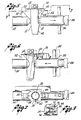
- FIG. 1 is a perspective view of a dedicated drip chamber and sensing unit embodying the invention installed in an IV administration system.
- FIG. 2 is a perspective view on an enlarged scale of the sensing unit.
- FIG. 3 is an enlarged fragmentary perspective view of a portion of the sensing unit taken in the direction of the arrowed
line 3 in FIG. 2. - FIG. 4 is an elevational view, with certain parts shown in longitudinal section, of the drip chamber and sensing unit in operable relation.
- FIG. 5 is an elevational view of the sensing unit in the initial stage of installation on the drip chamber.
- FIG. 6 is an elevational view of the sensing unit at a further stage of installation (phantom lines) and finally installed (solid lines) on the drip chamber.
- FIG. 7 is an elevational view taken along the line 7-7 in FIG. 5, with certain portions being shown in section.
- FIG. 8 is a fragmentary sectional view of the contact between the wing and the latch post taken along line 8-8 in FIG. 6.
- As shown in the drawings for purposes of illustration, and particularly in FIG. 1 thereof, the presently preferred embodiment of the invention includes a dedicated
disposable drip chamber 12 and a specifically designed,reusable sensing unit 13 actuable for installation on or removal from thedrip chamber 12. This assembly is intended for use as a component part of asolution administration system 16 wherein abottle 18 suspended from ahook 20 feeds the dripping of fluid through thedrip chamber 12 into adelivery tube 22. The electronic signals, initiated in thesensing unit 13 as each drop breaks a light beam, are transmitted to electronic signal conditioning, counting, and integrating means (not shown) throughsignal cable 24 to allow remote and automatic monitoring of solution administration. - In accordance with the present invention and most easily observed in FIG. 4, the
drip chamber 12 is provided with a generally ellipticallyshaped cantilever wing 14 mounted at the upper end 44 of thedrip chamber 12. The photoelectric sensing means is contained within the body of thesensing unit 13, and for proper operation the photoelectric sensing means must be mounted so that theoptical path 94 is normal to the drip chambercylindrical axis 26 at a fixed distance below thecantilever wing 14. - The
first housing section 30 is provided with a conforming surface 28 (FIG. 2) having proper curvature for conforming to the lateralcylindrical surface 11 ofdrip chamber 12. This conformingsurface 28 is vertically spaced fromcantilever wing 14 along the drip chambercylindrical axis 26. A stabilizingpost 32 is mounted on thefirst housing section 30 so that it may be placed in contact with and rest against the underside of thecantilever wing 14. Alatch post 34 presenting aninclined plane 68 to cantileverwing 14 is mounted to asleeve 36 slidably mounted over asecond housing section 38. The latch post 34 may be engaged to thecantilever wing 14 by retracting thesleeve 36 and then urging the sleeve forward by spring biasing action until contact is achieved. - It is found that the contacts produced by the conforming
surface 28, the stabilizingpost 32 and thelatch post 34 result in a stable, easily attached and detached mount. Thus, retention is achieved by a detached mount. Thus, retention is achieved by a combination of engaging of two contact surfaces and the latching of thelatch post 34 to cantileverwing 14. - The
drip chamber 12 for delivering fluid frombottle 18 todelivery tube 22 is generally of hollow tubular form and consists of acylindrical portion 40 joined to a lowerconical portion 42 whosesmall end 46 is suitable for receivingdelivery tube 22. Near the upper end 44 and lying substantially on the drip chambercylindrical axis 26 of thecylindrical portion 40 is located a drop former 48. The drop former 48 is a precision hollow tube which emits drops of fluid at a precise size determined by its dimensions. Thedrip chamber 12 thereby serves as a precision metering device in thesolution administration system 16. - To allow attachment of the
sensing unit 13, thedrip chamber 12 is provided with a plurality of cantilever projections oppositely disposed in pairs across a diameter of thecylindrical portion 40. In the preferred embodiment, thecantilever wing 14 defines a pair of projections firmly attached transversely to the drip chambercylindrical axis 26 near the upper end 44 of thecylindrical portion 42. Thecantilever wing 14 is substantially flat and of generally elliptical shape, preferably formed of a single piece of plastic or like material. The shape of theend portion 50 found at either elongated end of thecantilever wing 14 is suitably narrowed to mate with thelatch post 34, allowing attachment of thesensing unit 13. Thecantilever wing 14 is symmetrical about its shorter axis, thereby allowing thelatch post 34 to be mated with eithernarrow end portion 50. - The
sensing unit 13 generally comprises a tubular housing with acentral sensing gap 52 for receiving thedrip chamber 12. The tubular housing includes afirst housing section 30 containing thelight source 53 and asecond housing section 38 containing thephotocell 54 and supporting thesleeve 36. The twosections external bridging member 56. Hollow bridgingmember 56 allows electrical communication betweensections - The
first housing section 30 provides two of the contact surfaces for orienting thesensing unit 13 properly in relation to thedrip chamber 12. A conformingsurface 28 on the portion of thefirst housing section 30 adjacent thesensing gap 52 is adapted to contact the lateralcylindrical surface 11 ofdrip chamber 12. The stabilizingpost 32 is adapted to contact and rest against the lower side of thecantilever wing 14 at the stabilizingpost contact surface 58. Thelight source 53 is located in afirst cavity 60 within thefirst housing section 30. -
Second housing section 38 contains asecond cavity 88 for receivingphotocell 54.Sleeve 38 also supports spring-biasedsleeve 36.Sleeve 36 is biased toward thesensing gap 52 byspring 78 carried within thesecond housing section 38. The limit of movement ofsleeve 36 is defined by the motion ofrod 80 inslot 82. The length of bridgingmember 56 is chosen so that the minimum spacing along theoptical path 94 between facingend 90 ofsleeve 36 and facingend 92 offirst housing section 30 is substantially larger than the diameter ofcylindrical portion 40, so that sensingunit 13 may not be clamped directly using both facing ends 90 and 92 to the lateralcylindrical surface 11. -
Rod 80 also conveniently supports a pair offinger grip rods 84 mounted radially outward from opposite sides ofsleeve 36. In conjunction with the enlarged outersealed end 86 therods 84 forms a syringe-type grip familiar to medical personnel for selectively retracting the sleeve to enable mounting or removal ofsensing unit 13.Sleeve 36 carries alatch post 34 adapted for engaging theend portion 50 ofcantilever wing 14.Latch post 34 includesside members top member 66. Theside members inclined plane surface 68. The inclined edges 70 and 72 of theside members bevel surfaces 74 and 76 to generally conform to the curvature of the end portion 50 (FIG. 8) thereby promoting a camming action of movement ofend portion 50 into proper contact withtop member 66 during attachment procedures. - Attachment of
sensing unit 13 todrip chamber 12 is accomplished as shown in the sequence FIG. 5, FIG. 6 and FIG. 4.Sleeve 36 is first retracted by compressingspring 78 through opposing pressure onrods 84 and sealedend 86.Sensing unit 13 is moved into its approximate position withdrip chamber 12 lying generally withinsensing gap 52. This approximate positioning may be accomplished by moving sensingunit 13 generally along a radius ofcylindrical portion 40 rather than parallel to the drip chambercylindrical axis 26. This ability to introduce thesensing unit 13 from the side using only a single hand rather than from below represents a significant convenience feature for hospital personnel. - During a normal attachment procedure after the approximate positioning of
sensing unit 13 but beforespring 78 is released, there may be some misorientation between the sensingunit 13 anddrip chamber 12, as shown in FIG. 6. Final positioning is achieved by first movingsensing unit 13 in a generally axial direction upward until stabilizingpost 32 contacts the underside ofcantilever wing 14. Theend portion 50 then will have contactedside members inclined edges - Upon gradual releasing of tension in
spring 78,end portion 50 will be spring biased into position by engaginglatch post 34 by a cam action alonginclined edges drip chamber 12 is urged into its proper aligned position with the self-aligning action produced by movement ofsleeve 36. Assleeve 36 reaches its point of furthest travel towardsection 30, the lateralcylindrical surface 11 ofdrip chamber 12 achieves full contact with conformingsurface 28, stabilizingpost 32 contacts the underside ofcantilever wing 14 alongcontact surface 58 andend portion 50 completes engagement of latch post 34 by contacting the lower side oftop member 66.Sensing unit 13 is then securely but removably held todrip chamber 12 so thatoptical path 94 is substantially normal to thecylindrical axis 26 and by a fixed axial location. - By virtue of the engagement cooperation between
latch post 34 andcantilever wing 14 and the limitation on the extent of the closing movement of sfeeve.36 byrod 80 inslot 82, sensingunit 13 cannot be directly clamped on a drip chamber having nocantilever wing 14 or functional equivalent. If an attempt is made to mountsensing unit 13 on such an improper drip chamber, the loose fit will result insensing unit 13 falling away from the drip chamber or otherwise indicating the error to an attendant, thereby aiding in preventing use of an improper set. - It will now be appreciated that, through use of this invention, a sensing unit may be securely mounted to a drip chamber in the proper operating position easily and securely using only one hand. Additionally, the cooperating arrangement of projections on the drip chamber and the described latching mechanism on the drop sensor aid in preventing use of the drop sensor with any drip chamber for which it is not specifically designed.
Claims (6)
characterized by:
Applications Claiming Priority (2)
| Application Number | Priority Date | Filing Date | Title |
|---|---|---|---|
| US06/204,771 US4397648A (en) | 1980-11-07 | 1980-11-07 | Drop sensing unit and associated drip chamber for IV fluid administration |
| US204771 | 1998-12-03 |
Publications (3)
| Publication Number | Publication Date |
|---|---|
| EP0064548A1 EP0064548A1 (en) | 1982-11-17 |
| EP0064548A4 EP0064548A4 (en) | 1984-07-24 |
| EP0064548B1 true EP0064548B1 (en) | 1988-01-27 |
Family
ID=22759372
Family Applications (1)
| Application Number | Title | Priority Date | Filing Date |
|---|---|---|---|
| EP82900057A Expired EP0064548B1 (en) | 1980-11-07 | 1981-11-03 | Drops sensing unit and associated drip chamber for iv fluid administration |
Country Status (6)
| Country | Link |
|---|---|
| US (2) | US4397648A (en) |
| EP (1) | EP0064548B1 (en) |
| JP (1) | JPH0416186B2 (en) |
| CA (1) | CA1164756A (en) |
| DE (1) | DE3176627D1 (en) |
| WO (1) | WO1982001653A1 (en) |
Families Citing this family (64)
| Publication number | Priority date | Publication date | Assignee | Title |
|---|---|---|---|---|
| US4496351A (en) * | 1982-04-05 | 1985-01-29 | Ipco Corporation | Infusion monitor |
| US4680977A (en) * | 1985-03-06 | 1987-07-21 | Ivac Corporation | Optical flow sensor |
| US4668216A (en) * | 1985-03-11 | 1987-05-26 | Ivac Corporation | System for mounting a drop sensor to a drip chamber |
| US4681569A (en) * | 1985-03-22 | 1987-07-21 | Coble Stephen J | IV rate meter |
| DE3605319A1 (en) * | 1986-02-19 | 1987-08-20 | Pfrimmer Viggo Gmbh Co Kg | INFUSION DEVICE |
| US4986821A (en) * | 1986-05-28 | 1991-01-22 | Kamen Dean L | Drop detection housing with positive tactile signaling |
| CA1317179C (en) * | 1986-05-28 | 1993-05-04 | Deka Products Limited Partnership | Drop detector housing with positive tactile signaling |
| US5002539A (en) * | 1987-04-08 | 1991-03-26 | Coble Stephen J | IV rate meter |
| US4834744A (en) * | 1987-11-04 | 1989-05-30 | Critikon, Inc. | Spike for parenteral solution container |
| US5045069A (en) * | 1989-01-17 | 1991-09-03 | Robert Imparato | Portable infusion monitor |
| US5139482A (en) * | 1990-01-18 | 1992-08-18 | Simeon Paula S | Fluid infusion line monitor |
| WO1991012834A1 (en) * | 1990-02-28 | 1991-09-05 | Kent Archibald G | Automatic iv clamp |
| US5147313A (en) * | 1990-10-22 | 1992-09-15 | Entracare Corporation | Medical fluid delivery system with uniquely configured pump unit and fluid delivery set |
| USD383206S (en) * | 1990-10-22 | 1997-09-02 | Nutricare Medical Products, Inc. | Medical fluid drip container |
| US5186057A (en) * | 1991-10-21 | 1993-02-16 | Everhart Howard R | Multi-beam liquid-drop size/rate detector apparatus |
| AU3694793A (en) * | 1992-04-15 | 1993-10-21 | Fisher & Paykel Limited | Liquid supply apparatus |
| US5334170A (en) | 1993-07-14 | 1994-08-02 | Abbott Laboratories | Dye management system including an administration set with an in-line burette |
| US5575779A (en) * | 1994-12-30 | 1996-11-19 | Namic U.S.A. Corporation | Liquid regulator and method of use |
| US5671736A (en) * | 1995-10-17 | 1997-09-30 | Graphic Controls Corporation | Fetal electrode product with easy-to-handle connector |
| US5843045A (en) * | 1997-01-17 | 1998-12-01 | Dupont; Frank Stuart | Infusion illuminator |
| US6824528B1 (en) | 1997-03-03 | 2004-11-30 | Medical Solutions, Inc. | Method and apparatus for pressure infusion and temperature control of infused liquids |
| US6467953B1 (en) | 1999-03-30 | 2002-10-22 | Medical Solutions, Inc. | Method and apparatus for monitoring temperature of intravenously delivered fluids and other medical items |
| US5938643A (en) * | 1997-07-10 | 1999-08-17 | Unisor Multisystems Ltd | Drop monitoring unit for infusion sets |
| GB9803299D0 (en) | 1998-02-18 | 1998-04-08 | Gallagher George | Improved method and apparatus for monitoring intravenous drips |
| US7255680B1 (en) | 1999-10-27 | 2007-08-14 | Cardinal Health 303, Inc. | Positive pressure infusion system having downstream resistance measurement capability |
| US7238171B2 (en) | 2001-03-12 | 2007-07-03 | Medical Solutions, Inc. | Method and apparatus for controlling pressurized infusion and temperature of infused liquids |
| US6592126B2 (en) * | 2001-07-20 | 2003-07-15 | Flowserve Management Company | Mechanical seal leak detector |
| US8226605B2 (en) | 2001-12-17 | 2012-07-24 | Medical Solutions, Inc. | Method and apparatus for heating solutions within intravenous lines to desired temperatures during infusion |
| US7611504B1 (en) | 2004-03-09 | 2009-11-03 | Patented Medical Solutions Llc | Method and apparatus for facilitating injection of medication into an intravenous fluid line while maintaining sterility of infused fluids |
| US7556619B2 (en) | 2004-04-16 | 2009-07-07 | Medrad, Inc. | Fluid delivery system having a fluid level sensor and a fluid control device for isolating a patient from a pump device |
| US7740611B2 (en) | 2005-10-27 | 2010-06-22 | Patented Medical Solutions, Llc | Method and apparatus to indicate prior use of a medical item |
| US8487738B2 (en) | 2006-03-20 | 2013-07-16 | Medical Solutions, Inc. | Method and apparatus for securely storing medical items within a thermal treatment system |
| US20080051732A1 (en) * | 2006-06-23 | 2008-02-28 | Thaiping Chen | Drop sensing device for monitoring intravenous fluid flow |
| US8226293B2 (en) * | 2007-02-22 | 2012-07-24 | Medical Solutions, Inc. | Method and apparatus for measurement and control of temperature for infused liquids |
| US9993619B2 (en) * | 2007-07-17 | 2018-06-12 | C. R. Bard, Inc. | Securement system for a medical article |
| EP2519289B1 (en) * | 2009-12-30 | 2015-08-19 | Fredrik Svensson | Infusion control device |
| US9151646B2 (en) | 2011-12-21 | 2015-10-06 | Deka Products Limited Partnership | System, method, and apparatus for monitoring, regulating, or controlling fluid flow |
| US8531517B2 (en) * | 2010-07-15 | 2013-09-10 | Kai Tao | IV monitoring by video and image processing |
| US10488848B2 (en) | 2011-12-21 | 2019-11-26 | Deka Products Limited Partnership | System, method, and apparatus for monitoring, regulating, or controlling fluid flow |
| US9435455B2 (en) | 2011-12-21 | 2016-09-06 | Deka Products Limited Partnership | System, method, and apparatus for monitoring, regulating, or controlling fluid flow |
| US9746094B2 (en) | 2011-12-21 | 2017-08-29 | Deka Products Limited Partnership | Flow meter having a background pattern with first and second portions |
| US9724466B2 (en) | 2011-12-21 | 2017-08-08 | Deka Products Limited Partnership | Flow meter |
| US9372486B2 (en) | 2011-12-21 | 2016-06-21 | Deka Products Limited Partnership | System, method, and apparatus for monitoring, regulating, or controlling fluid flow |
| US9746093B2 (en) | 2011-12-21 | 2017-08-29 | Deka Products Limited Partnership | Flow meter and related system and apparatus |
| US10228683B2 (en) | 2011-12-21 | 2019-03-12 | Deka Products Limited Partnership | System, method, and apparatus for monitoring, regulating, or controlling fluid flow |
| US9211381B2 (en) | 2012-01-20 | 2015-12-15 | Medical Solutions, Inc. | Method and apparatus for controlling temperature of medical liquids |
| WO2014070781A2 (en) | 2012-10-29 | 2014-05-08 | Hospira, Inc. | Fluid flow passage to improve air-in-line detection |
| US9759343B2 (en) | 2012-12-21 | 2017-09-12 | Deka Products Limited Partnership | Flow meter using a dynamic background image |
| JP2014140467A (en) * | 2013-01-23 | 2014-08-07 | Tatsuta Electric Wire & Cable Co Ltd | Drip speed measuring instrument |
| WO2014126964A1 (en) | 2013-02-15 | 2014-08-21 | Medical Solutions, Inc. | Plural medical item warming system and method for warming a plurality of medical items to desired temperatures |
| USD751689S1 (en) | 2013-11-06 | 2016-03-15 | Deka Products Limited Partnership | Apparatus to control fluid flow through a tube |
| USD745661S1 (en) | 2013-11-06 | 2015-12-15 | Deka Products Limited Partnership | Apparatus to control fluid flow through a tube |
| USD749206S1 (en) | 2013-11-06 | 2016-02-09 | Deka Products Limited Partnership | Apparatus to control fluid flow through a tube |
| USD751690S1 (en) | 2013-11-06 | 2016-03-15 | Deka Products Limited Partnership | Apparatus to control fluid flow through a tube |
| USD752209S1 (en) | 2013-11-06 | 2016-03-22 | Deka Products Limited Partnership | Apparatus to control fluid flow through a tube |
| US20150133861A1 (en) | 2013-11-11 | 2015-05-14 | Kevin P. McLennan | Thermal management system and method for medical devices |
| US10143795B2 (en) | 2014-08-18 | 2018-12-04 | Icu Medical, Inc. | Intravenous pole integrated power, control, and communication system and method for an infusion pump |
| AU2016267763B2 (en) | 2015-05-26 | 2021-07-08 | Icu Medical, Inc. | Disposable infusion fluid delivery device for programmable large volume drug delivery |
| USD905848S1 (en) | 2016-01-28 | 2020-12-22 | Deka Products Limited Partnership | Apparatus to control fluid flow through a tube |
| MX2018009239A (en) | 2016-01-28 | 2019-02-07 | Deka Products Lp | Apparatus for monitoring, regulating, or controlling fluid flow. |
| USD854145S1 (en) | 2016-05-25 | 2019-07-16 | Deka Products Limited Partnership | Apparatus to control fluid flow through a tube |
| USD964563S1 (en) | 2019-07-26 | 2022-09-20 | Deka Products Limited Partnership | Medical flow clamp |
| US11839741B2 (en) | 2019-07-26 | 2023-12-12 | Deka Products Limited Partneship | Apparatus for monitoring, regulating, or controlling fluid flow |
| USD939079S1 (en) | 2019-08-22 | 2021-12-21 | Icu Medical, Inc. | Infusion pump |
Family Cites Families (13)
| Publication number | Priority date | Publication date | Assignee | Title |
|---|---|---|---|---|
| US3428393A (en) * | 1965-11-05 | 1969-02-18 | Roger Lannes De Montebello | Optical dissector |
| US3500366A (en) * | 1966-10-03 | 1970-03-10 | Gen Instrument Corp | Monitoring system for fluid flow in drop form |
| US3449952A (en) * | 1967-05-19 | 1969-06-17 | Amp Inc | Drop-count attachment |
| US3596515A (en) * | 1967-11-27 | 1971-08-03 | Ivac Corp | Drop flow sensor and resilient clamp therefor |
| US3462213A (en) * | 1968-08-26 | 1969-08-19 | Roger Lannes De Montebello | Three-dimensional optical display apparatus |
| GB1458926A (en) * | 1974-06-18 | 1976-12-15 | Denner J R | Cameras and enlargers |
| CH585069A5 (en) * | 1974-07-05 | 1977-02-28 | Wuilleret Bernard | Plastic dropper bottle as medical sample tube - has a stopper at one end, and a cap over the dropper at the other |
| US4038981A (en) * | 1974-07-26 | 1977-08-02 | Burron Medical Products, Inc. | Electronically controlled intravenous infusion set |
| JPS5127131A (en) * | 1974-08-30 | 1976-03-06 | Hitachi Ltd | |
| JPS5158950A (en) * | 1974-11-20 | 1976-05-22 | Tokyo Shibaura Electric Co | FUIRUMUSOZOSOCHI |
| US4038982A (en) * | 1975-12-03 | 1977-08-02 | Burron Medical Products, Inc. | Electrically controlled intravenous infusion set |
| US4346606A (en) * | 1980-03-10 | 1982-08-31 | Imed Corporation | Rate meter |
| US4321461A (en) * | 1980-04-18 | 1982-03-23 | K/W/D Associates | Flow rate monitor and totalizer with count display |
-
1980
- 1980-11-07 US US06/204,771 patent/US4397648A/en not_active Ceased
-
1981
- 1981-11-03 DE DE8282900057T patent/DE3176627D1/en not_active Expired
- 1981-11-03 WO PCT/US1981/001483 patent/WO1982001653A1/en active IP Right Grant
- 1981-11-03 JP JP57500062A patent/JPH0416186B2/ja not_active Expired - Lifetime
- 1981-11-03 EP EP82900057A patent/EP0064548B1/en not_active Expired
- 1981-11-04 CA CA000389395A patent/CA1164756A/en not_active Expired
-
1985
- 1985-08-02 US US06/762,051 patent/USRE32294E/en not_active Expired - Lifetime
Also Published As
| Publication number | Publication date |
|---|---|
| JPS57501942A (en) | 1982-11-04 |
| WO1982001653A1 (en) | 1982-05-27 |
| EP0064548A4 (en) | 1984-07-24 |
| USRE32294E (en) | 1986-11-25 |
| EP0064548A1 (en) | 1982-11-17 |
| DE3176627D1 (en) | 1988-03-03 |
| US4397648A (en) | 1983-08-09 |
| CA1164756A (en) | 1984-04-03 |
| JPH0416186B2 (en) | 1992-03-23 |
Similar Documents
| Publication | Publication Date | Title |
|---|---|---|
| EP0064548B1 (en) | Drops sensing unit and associated drip chamber for iv fluid administration | |
| US4668216A (en) | System for mounting a drop sensor to a drip chamber | |
| US3596515A (en) | Drop flow sensor and resilient clamp therefor | |
| US5328466A (en) | Syringe and needle assembly | |
| EP0346548B1 (en) | Empty container detector | |
| CA2015558C (en) | Air detector for use in infusion pump | |
| EP0255025B1 (en) | Device for coupling a small tube to an apparatus adapted for fitting a syringe to a drug holding bottle | |
| US4681569A (en) | IV rate meter | |
| US8814830B2 (en) | Syringe plunger driver system | |
| US4394862A (en) | Metering apparatus with downline pressure monitoring system | |
| EP0416912B1 (en) | Automatic tubing lock for ultrasonic sensor interface | |
| EP0481656B1 (en) | Air detector for thin walled tubes | |
| US5622869A (en) | Method of detecting an obstruction in a fluid flow line of a medical laboratory instrument | |
| US4176349A (en) | Intravenous alarm system | |
| EP0165262A1 (en) | Volumetric pump with replaceable reservoir assembly. | |
| JPH01148272A (en) | Spike for parenteral liquid container | |
| US3993065A (en) | Fluid infusion apparatus | |
| EP0340899A3 (en) | Syringe | |
| JPH05507869A (en) | peristaltic infusion device | |
| CA1326193C (en) | Hub configuration | |
| JPH0233390B2 (en) | ||
| US5814275A (en) | Obstruction detector for a fluid flow line of a medical laboratory instrument | |
| KR20150133723A (en) | Apparatus for receiving a syringe into a fluid-dispensing apparatus, method therefor, and use of such a receptacle | |
| EP2171476B1 (en) | Autonomous syringe and grid systems | |
| EP0388102A2 (en) | Improvements in infusion pumps |
Legal Events
| Date | Code | Title | Description |
|---|---|---|---|
| PUAI | Public reference made under article 153(3) epc to a published international application that has entered the european phase |
Free format text: ORIGINAL CODE: 0009012 |
|
| AK | Designated contracting states |
Designated state(s): CH DE FR GB LI |
|
| 17P | Request for examination filed |
Effective date: 19821123 |
|
| RBV | Designated contracting states (corrected) |
Designated state(s): CH DE FR GB LI |
|
| GRAA | (expected) grant |
Free format text: ORIGINAL CODE: 0009210 |
|
| AK | Designated contracting states |
Kind code of ref document: B1 Designated state(s): CH DE FR GB LI |
|
| REF | Corresponds to: |
Ref document number: 3176627 Country of ref document: DE Date of ref document: 19880303 |
|
| ET | Fr: translation filed | ||
| PLBE | No opposition filed within time limit |
Free format text: ORIGINAL CODE: 0009261 |
|
| STAA | Information on the status of an ep patent application or granted ep patent |
Free format text: STATUS: NO OPPOSITION FILED WITHIN TIME LIMIT |
|
| 26N | No opposition filed | ||
| PGFP | Annual fee paid to national office [announced via postgrant information from national office to epo] |
Ref country code: CH Payment date: 19950110 Year of fee payment: 14 |
|
| PG25 | Lapsed in a contracting state [announced via postgrant information from national office to epo] |
Ref country code: LI Effective date: 19951130 Ref country code: CH Effective date: 19951130 |
|
| REG | Reference to a national code |
Ref country code: CH Ref legal event code: PL |
|
| REG | Reference to a national code |
Ref country code: FR Ref legal event code: CD Ref country code: FR Ref legal event code: CA |
|
| REG | Reference to a national code |
Ref country code: GB Ref legal event code: 732E |
|
| REG | Reference to a national code |
Ref country code: FR Ref legal event code: TP Ref country code: FR Ref legal event code: CD |
|
| PGFP | Annual fee paid to national office [announced via postgrant information from national office to epo] |
Ref country code: FR Payment date: 19991019 Year of fee payment: 19 |
|
| PGFP | Annual fee paid to national office [announced via postgrant information from national office to epo] |
Ref country code: GB Payment date: 19991020 Year of fee payment: 19 Ref country code: DE Payment date: 19991020 Year of fee payment: 19 |
|
| PG25 | Lapsed in a contracting state [announced via postgrant information from national office to epo] |
Ref country code: GB Free format text: LAPSE BECAUSE OF NON-PAYMENT OF DUE FEES Effective date: 20001103 |
|
| GBPC | Gb: european patent ceased through non-payment of renewal fee |
Effective date: 20001103 |
|
| PG25 | Lapsed in a contracting state [announced via postgrant information from national office to epo] |
Ref country code: FR Free format text: LAPSE BECAUSE OF NON-PAYMENT OF DUE FEES Effective date: 20010731 |
|
| PG25 | Lapsed in a contracting state [announced via postgrant information from national office to epo] |
Ref country code: DE Free format text: LAPSE BECAUSE OF NON-PAYMENT OF DUE FEES Effective date: 20010801 |
|
| REG | Reference to a national code |
Ref country code: FR Ref legal event code: ST |