EP0069942A2 - Driving device for an endoscopic-treatment instrument - Google Patents
Driving device for an endoscopic-treatment instrument Download PDFInfo
- Publication number
- EP0069942A2 EP0069942A2 EP82105935A EP82105935A EP0069942A2 EP 0069942 A2 EP0069942 A2 EP 0069942A2 EP 82105935 A EP82105935 A EP 82105935A EP 82105935 A EP82105935 A EP 82105935A EP 0069942 A2 EP0069942 A2 EP 0069942A2
- Authority
- EP
- European Patent Office
- Prior art keywords
- forceps
- endoscope
- treatment
- treatment instrument
- driving device
- Prior art date
- Legal status (The legal status is an assumption and is not a legal conclusion. Google has not performed a legal analysis and makes no representation as to the accuracy of the status listed.)
- Granted
Links
Images


Classifications
-
- A—HUMAN NECESSITIES
- A61—MEDICAL OR VETERINARY SCIENCE; HYGIENE
- A61B—DIAGNOSIS; SURGERY; IDENTIFICATION
- A61B10/00—Other methods or instruments for diagnosis, e.g. instruments for taking a cell sample, for biopsy, for vaccination diagnosis; Sex determination; Ovulation-period determination; Throat striking implements
- A61B10/02—Instruments for taking cell samples or for biopsy
-
- A—HUMAN NECESSITIES
- A61—MEDICAL OR VETERINARY SCIENCE; HYGIENE
- A61B—DIAGNOSIS; SURGERY; IDENTIFICATION
- A61B1/00—Instruments for performing medical examinations of the interior of cavities or tubes of the body by visual or photographical inspection, e.g. endoscopes; Illuminating arrangements therefor
- A61B1/00064—Constructional details of the endoscope body
- A61B1/00071—Insertion part of the endoscope body
- A61B1/0008—Insertion part of the endoscope body characterised by distal tip features
- A61B1/00098—Deflecting means for inserted tools
-
- A—HUMAN NECESSITIES
- A61—MEDICAL OR VETERINARY SCIENCE; HYGIENE
- A61B—DIAGNOSIS; SURGERY; IDENTIFICATION
- A61B1/00—Instruments for performing medical examinations of the interior of cavities or tubes of the body by visual or photographical inspection, e.g. endoscopes; Illuminating arrangements therefor
- A61B1/005—Flexible endoscopes
- A61B1/0058—Flexible endoscopes using shape-memory elements
-
- A—HUMAN NECESSITIES
- A61—MEDICAL OR VETERINARY SCIENCE; HYGIENE
- A61B—DIAGNOSIS; SURGERY; IDENTIFICATION
- A61B17/00—Surgical instruments, devices or methods, e.g. tourniquets
- A61B17/28—Surgical forceps
- A61B17/29—Forceps for use in minimally invasive surgery
-
- A—HUMAN NECESSITIES
- A61—MEDICAL OR VETERINARY SCIENCE; HYGIENE
- A61B—DIAGNOSIS; SURGERY; IDENTIFICATION
- A61B17/00—Surgical instruments, devices or methods, e.g. tourniquets
- A61B17/32—Surgical cutting instruments
- A61B17/320016—Endoscopic cutting instruments, e.g. arthroscopes, resectoscopes
-
- A—HUMAN NECESSITIES
- A61—MEDICAL OR VETERINARY SCIENCE; HYGIENE
- A61B—DIAGNOSIS; SURGERY; IDENTIFICATION
- A61B17/00—Surgical instruments, devices or methods, e.g. tourniquets
- A61B17/00234—Surgical instruments, devices or methods, e.g. tourniquets for minimally invasive surgery
- A61B2017/00292—Surgical instruments, devices or methods, e.g. tourniquets for minimally invasive surgery mounted on or guided by flexible, e.g. catheter-like, means
- A61B2017/003—Steerable
-
- A—HUMAN NECESSITIES
- A61—MEDICAL OR VETERINARY SCIENCE; HYGIENE
- A61B—DIAGNOSIS; SURGERY; IDENTIFICATION
- A61B17/00—Surgical instruments, devices or methods, e.g. tourniquets
- A61B17/28—Surgical forceps
- A61B17/29—Forceps for use in minimally invasive surgery
- A61B2017/2901—Details of shaft
- A61B2017/2905—Details of shaft flexible
-
- A—HUMAN NECESSITIES
- A61—MEDICAL OR VETERINARY SCIENCE; HYGIENE
- A61F—FILTERS IMPLANTABLE INTO BLOOD VESSELS; PROSTHESES; DEVICES PROVIDING PATENCY TO, OR PREVENTING COLLAPSING OF, TUBULAR STRUCTURES OF THE BODY, e.g. STENTS; ORTHOPAEDIC, NURSING OR CONTRACEPTIVE DEVICES; FOMENTATION; TREATMENT OR PROTECTION OF EYES OR EARS; BANDAGES, DRESSINGS OR ABSORBENT PADS; FIRST-AID KITS
- A61F2/00—Filters implantable into blood vessels; Prostheses, i.e. artificial substitutes or replacements for parts of the body; Appliances for connecting them with the body; Devices providing patency to, or preventing collapsing of, tubular structures of the body, e.g. stents
- A61F2/02—Prostheses implantable into the body
- A61F2/30—Joints
- A61F2002/30001—Additional features of subject-matter classified in A61F2/28, A61F2/30 and subgroups thereof
- A61F2002/30003—Material related properties of the prosthesis or of a coating on the prosthesis
- A61F2002/3006—Properties of materials and coating materials
- A61F2002/30092—Properties of materials and coating materials using shape memory or superelastic materials, e.g. nitinol
-
- A—HUMAN NECESSITIES
- A61—MEDICAL OR VETERINARY SCIENCE; HYGIENE
- A61F—FILTERS IMPLANTABLE INTO BLOOD VESSELS; PROSTHESES; DEVICES PROVIDING PATENCY TO, OR PREVENTING COLLAPSING OF, TUBULAR STRUCTURES OF THE BODY, e.g. STENTS; ORTHOPAEDIC, NURSING OR CONTRACEPTIVE DEVICES; FOMENTATION; TREATMENT OR PROTECTION OF EYES OR EARS; BANDAGES, DRESSINGS OR ABSORBENT PADS; FIRST-AID KITS
- A61F2210/00—Particular material properties of prostheses classified in groups A61F2/00 - A61F2/26 or A61F2/82 or A61F9/00 or A61F11/00 or subgroups thereof
- A61F2210/0014—Particular material properties of prostheses classified in groups A61F2/00 - A61F2/26 or A61F2/82 or A61F9/00 or A61F11/00 or subgroups thereof using shape memory or superelastic materials, e.g. nitinol
- A61F2210/0023—Particular material properties of prostheses classified in groups A61F2/00 - A61F2/26 or A61F2/82 or A61F9/00 or A61F11/00 or subgroups thereof using shape memory or superelastic materials, e.g. nitinol operated at different temperatures whilst inside or touching the human body, heated or cooled by external energy source or cold supply
- A61F2210/0033—Particular material properties of prostheses classified in groups A61F2/00 - A61F2/26 or A61F2/82 or A61F9/00 or A61F11/00 or subgroups thereof using shape memory or superelastic materials, e.g. nitinol operated at different temperatures whilst inside or touching the human body, heated or cooled by external energy source or cold supply electrically, e.g. heated by resistor
Definitions
- the present invention relates to a treatment instrument driving device for altering the direction of a treatment instrument, e.g., forceps to be guided to a body cavity through the channel of an endoscope.
- the endoscope has been used not only for the observation or the photographing of the interior of a body cavity from the exterior, but also for the collection of the pathological tissue in the body cavity by forceps or the therapy of the tissue with a simple operation implement.
- a treatment instrument driving device for moving forceps or an operation implement to be guided into a body cavity through the channel of an endoscope to an objective position has become an important factor in the endoscope.
- a driving member is arranged in a distal closet provided at the distal portion of an endoscope, being pivotally secured at its one end to the distal portion, and engaged at its other end to an operation wire inserted into the guide tube of the endoscope.
- the driving member thus rises when the operation wire is pulled, and forceps are then moved to a predetermined position according to the rising angle of the operation wire.
- the contaminated solid or liquid thus accumulated in the gap not only prevents the rising of the driving member due to the operation wire, but is also unsanitary. Further, the treatment instrument driving device is used in the very narrow position of the endoscope. Accordingly, a problem occurs in the cleaning treatment of the narrow position after use.
- a driving member i.e., forceps raiser of a treatment instrument driving device, formed, for example, of a shape memory alloy, is installed so as not to produce a gap in the distal closet of an endoscope.
- An electric current is thus supplied to the forceps raiser to vary the temperature thereof.
- the forceps raiser is heated due to the current supply, and is thereby deformed. As a result, the forceps are displaced by the forceps raiser.
- a side-viewing endoscope 1 is constituted by a control section 2, an insertion section 3, a flexible section 4, a bending section 5 and a distal portion 6.
- An operation knob 7 for bending and operating the bending section 5 is provided at the side of the control section 2, and an eyepiece 8 is provided at the upper portion.
- a forceps channel inlet 9 and suction and air/water feeding buttons 10 are provided at the control section 2 at the control section 2 .
- a universal cord 11 extends from the control section 2, and a connector lla provided at the end of the universal cord 11 is connected to a light supply unit 30.
- An illumination window 12 and an observation window 13 are provided, as shown in Fig. 2, to be aligned longitudinally at one side of the side surface of the distal portion 6.
- a forceps closet 14 is formed at the other side of the side surface of the distal portion 6.
- the illumination light of the light supply unit 30 is emitted from the illumination window 12 through a light guide (not shown) of the endoscope 1, and the portion illuminated by the illumination light can be observed by the eyepiece 8 through the observation window 13 and an image guide (not shown) of the endoscope 1.
- a forceps channel 15 passing from the forceps channel inlet 9 provided at the endoscope 1 through the control section 2, the insertion section 3, the flexible section 4 and the bending section 5 to the distal portion 6 is provided in the endoscope 8.
- the end of the channel 15 communicates with the forceps closet 14.
- a planar forceps raiser 17 is disposed at the back position of the protruded forceps 16 at the forceps closet 14, and the forceps raiser 17 is closely contacted with the open end formed at the rear wall 14a of the forceps closet 14.
- the forceps raiser 17 is formed of Cu-Zn-At alloy or Ti-Ni alloy having shape memory effect, and is covered, for example, with an elastic member, such as a rubber 18.
- the forceps raiser 17 is so composed as to bend to a great extent as the temperature rises.
- the crystalline structure of the shape memory alloy forming the forceps raiser 17 becomes mother phase at the high temperature, the forceps raiser 17 thus bends to a great extent, but is plastically deformed at room temperature at which it bends slightly.
- the shape memory alloy forming the forceps raiser 17 is so formed that the temperature starting the inverse transformation from the martensite phase to the mother phase becomes higher than the body temperature.
- Lead lines 19 are respectively connected, as shown in Fig. 3, to both the ends of the forcep raiser 17 and are connected to the terminals of a power source 21 through the resistor 22 and the switch 23 of a power unit 20.
- the resistor 22 and the switch 23 are provided in the control section 2 and the power source 21 is provided in the light supply unit 30.
- Fig. 4 shows the section of the distal portion 6 along the line 4-4 in Fig. 3.
- the forceps raiser 17 When the current thus flows through the forceps raiser 17, the forceps raiser 17 is heated by the Joule heat. When the forceps raiser 17 is thus heated higher than the body temperature, the inverse transformation from the martensite to the mother phase will start, so that the forceps raiser 17 will bend to a great extent as shown in Fig. 5. As the forceps raiser 17 thus bends, the forceps 16 is raised by the forceps raiser 17, and the direction of the forceps 16 is altered. When the switch 23 is opened in this state, the current supply to the forceps raiser 17 is stopped, and the temperature of the forceps raiser 17 is resultantly lowered.
- the forceps raiser 17 When this temperature is decreased to body temperature, the forceps raiser 17 is plastically deformed to the state shown in Fig. 3 while the martensite transformation is being carried out. In this manner, the forceps 16 is returned to the original position.
- the magnitude of the bending of the forceps raiser 17 can be arbitrarily set by altering the current supplied to the forceps raiser 17 and resultantly varying the temperature of the forceps raiser 17 under the control of the resistor 22.
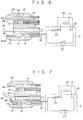
- a forceps raiser 17 is provided in the distal portion 6 of the forward-viewing type endoscope.
- a hood 24 protruded from the end face of the distal portion 6.
- An observation window 13 is provided in the distal portion 6, and is optically connected to an image guide fibers 27 through the lenses 26 of an optical system 25.
- a forceps channel 15 is provided in parallel with the optical system 25 and the image guide fiber 27, and the forceps 16 are inserted into the forceps channel 15.
- the forceps raiser 17 is mounted at the distal portion 6 in the proximity to the forceps channel 15. In this case, one end of the forceps raiser 17 covered with an elastic member 18 is closely contacted with the distal portion 6 so as not to form a gap with the distal portion 6. The other end of the forceps raiser 17 is inserted into the forceps raiser receiving hole 24a provided at the hood 24. Both ends of the forceps raiser 17 are connected to lead lines 19.
- the forceps raiser 17 when the forceps raiser 17 is not energized by the power unit 20, i.e., when the shape memory alloy is in martensite phase, the forceps raiser 17 becomes planar as shown in Fig. 6 and is thus contained in the forceps raiser receiving hole 24a.
- the switch 23 is closed to flow a current through the forceps raiser 17 so that the forceps raiser 17 is heated with the result that the shape memory alloy is transferred to the mother phase, the forceps raiser 17 bends to a great extent as shown in Fig. 7 to displace the forceps 16.
- the switch 23 is opened so that the temperature of the forceps raiser 17 is decreased to body temperature, the forceps raiser 17 returns to the planar state.
- the bending degree of the forceps raiser 17 is also controlled in this embodiment by altering the resistor 22.
- the forceps raiser is so provided at the forceps closet of the distal portion of the endoscope as not to form a gap with the wall of the forceps closet. It is formed of the shape memory alloy which alters its shape in response to the temperature.
- the power unit is connected to the forceps raiser formed of the shape memory alloy, and the temperature of the forceps raiser is adjusted by controlling the current from the power unit to the forceps raiser.
- the forceps raiser is thus displaced, and the position of the forceps can also be displaced. Since the forceps raising device thus composed does not substantially have a mechanical driving unit, its structure simple and small in size. Furthermore, no gap is formed through which contaminants can be introduced in the structure. Therefore, as the forceps raiser can operate without any problem, it is not necessary to increase the diameter of the distal portion and it remains sanitary.
Abstract
Description
- The present invention relates to a treatment instrument driving device for altering the direction of a treatment instrument, e.g., forceps to be guided to a body cavity through the channel of an endoscope.
- The endoscope has been used not only for the observation or the photographing of the interior of a body cavity from the exterior, but also for the collection of the pathological tissue in the body cavity by forceps or the therapy of the tissue with a simple operation implement. For that purpose, a treatment instrument driving device for moving forceps or an operation implement to be guided into a body cavity through the channel of an endoscope to an objective position has become an important factor in the endoscope.
- According to a conventional treatment instrument driving device, a driving member is arranged in a distal closet provided at the distal portion of an endoscope, being pivotally secured at its one end to the distal portion, and engaged at its other end to an operation wire inserted into the guide tube of the endoscope. The driving member thus rises when the operation wire is pulled, and forceps are then moved to a predetermined position according to the rising angle of the operation wire. With such a structure, a gap is produced between the operation wire and the guide tube, and the gap is exposed with the distal closet. Therefore, a contaminated solid or liquid is feasibly introduced into the gap. The contaminated solid or liquid thus accumulated in the gap not only prevents the rising of the driving member due to the operation wire, but is also unsanitary. Further, the treatment instrument driving device is used in the very narrow position of the endoscope. Accordingly, a problem occurs in the cleaning treatment of the narrow position after use.
- It is an object of the present invention to provide a treatment instrument driving device which can be provided in the distal closet of an endoscope without a gap, and which is sanitary with good operability.
- According to the present invention, a driving member, i.e., forceps raiser of a treatment instrument driving device, formed, for example, of a shape memory alloy, is installed so as not to produce a gap in the distal closet of an endoscope. An electric current is thus supplied to the forceps raiser to vary the temperature thereof. The forceps raiser is heated due to the current supply, and is thereby deformed. As a result, the forceps are displaced by the forceps raiser.
- This invention can be more fully understood from the following detailed description when taken in conjunction with the accompanying drawings, in which:
- Fig. 1 is a perspective view of an endoscope having a treatment instrument driving device according to one preferred embodiment of the present invention;
- Fig. 2 is a plan view of the distal portion of the endoscope in Fig. 1;
- Fig. 3 is a sectional view taken along the line 3-3 of the distal portion in Fig. 2;
- Fig. 4 is a plan sectional view of the distal portion in Fig. 2;
- Fig. 5 is a lateral sectional view of the distal portion when the forceps raiser is deformed;
- Fig. 6 is a sectional view of the distal portion having the forceps raiser according to another preferred embodiment of the present invention; and
- Fig. 7 is a sectional view of the distal portion when the forceps raiser is deformed.
- The present invention will now be described in more detail with reference to the accompanying drawings.
- In Fig. 1, A side-
viewing endoscope 1 is constituted by acontrol section 2, aninsertion section 3, aflexible section 4, abending section 5 and adistal portion 6. Anoperation knob 7 for bending and operating thebending section 5 is provided at the side of thecontrol section 2, and aneyepiece 8 is provided at the upper portion. At thecontrol section 2 are provided a forceps channel inlet 9 and suction and air/water feeding buttons 10. Auniversal cord 11 extends from thecontrol section 2, and a connector lla provided at the end of theuniversal cord 11 is connected to alight supply unit 30. - An
illumination window 12 and anobservation window 13 are provided, as shown in Fig. 2, to be aligned longitudinally at one side of the side surface of thedistal portion 6. Aforceps closet 14 is formed at the other side of the side surface of thedistal portion 6. - The illumination light of the
light supply unit 30 is emitted from theillumination window 12 through a light guide (not shown) of theendoscope 1, and the portion illuminated by the illumination light can be observed by theeyepiece 8 through theobservation window 13 and an image guide (not shown) of theendoscope 1. Aforceps channel 15 passing from the forceps channel inlet 9 provided at theendoscope 1 through thecontrol section 2, theinsertion section 3, theflexible section 4 and thebending section 5 to thedistal portion 6 is provided in theendoscope 8. The end of thechannel 15 communicates with theforceps closet 14. When the treatment instrument, i.e., theforceps 16 is therefore inserted from the forceps channel inlet 9 into thechannel 15, the end of theforceps 16 is protruded into theforceps closet 14. Aplanar forceps raiser 17 is disposed at the back position of the protrudedforceps 16 at theforceps closet 14, and theforceps raiser 17 is closely contacted with the open end formed at the rear wall 14a of theforceps closet 14. Theforceps raiser 17 is formed of Cu-Zn-At alloy or Ti-Ni alloy having shape memory effect, and is covered, for example, with an elastic member, such as arubber 18. Theforceps raiser 17 is so composed as to bend to a great extent as the temperature rises. In other words, the crystalline structure of the shape memory alloy forming theforceps raiser 17 becomes mother phase at the high temperature, the forceps raiser 17 thus bends to a great extent, but is plastically deformed at room temperature at which it bends slightly. In the preferred embodiment, the shape memory alloy forming theforceps raiser 17 is so formed that the temperature starting the inverse transformation from the martensite phase to the mother phase becomes higher than the body temperature. -
Lead lines 19 are respectively connected, as shown in Fig. 3, to both the ends of theforcep raiser 17 and are connected to the terminals of apower source 21 through theresistor 22 and theswitch 23 of apower unit 20. Theresistor 22 and theswitch 23 are provided in thecontrol section 2 and thepower source 21 is provided in thelight supply unit 30. When the connector lla at the end of theuniversal cord 11 of theendoscope 1 is connected to thelight supply unit 30, power is supplied to thepower unit 20. - In the forceps raising device thus composed, when the
endoscope 1 is inserted into the body cavity, the shape memory alloy of theforceps raiser 17 is in the martensite phase, and the forceps raiser 17 bends slightly. Fig. 4 shows the section of thedistal portion 6 along the line 4-4 in Fig. 3. When theforceps 16 is inserted into theforceps channel 15 in this state, theforceps 16 extends in a direction along the axis of thedistal portion 6 under the guidance of theforceps raiser 17. When theforceps 16 is displaced and hence raised in this state, theswitch 23 is closed to supply a current to theforceps raiser 17. When the current thus flows through the forceps raiser 17, theforceps raiser 17 is heated by the Joule heat. When theforceps raiser 17 is thus heated higher than the body temperature, the inverse transformation from the martensite to the mother phase will start, so that theforceps raiser 17 will bend to a great extent as shown in Fig. 5. As the forceps raiser 17 thus bends, theforceps 16 is raised by theforceps raiser 17, and the direction of theforceps 16 is altered. When theswitch 23 is opened in this state, the current supply to theforceps raiser 17 is stopped, and the temperature of theforceps raiser 17 is resultantly lowered. When this temperature is decreased to body temperature, theforceps raiser 17 is plastically deformed to the state shown in Fig. 3 while the martensite transformation is being carried out. In this manner, theforceps 16 is returned to the original position. The magnitude of the bending of theforceps raiser 17 can be arbitrarily set by altering the current supplied to theforceps raiser 17 and resultantly varying the temperature of the forceps raiser 17 under the control of theresistor 22. - Another preferred embodiment of the present invention will now be described in more detail with reference to Figs. 6 and 7. In this embodiment, a
forceps raiser 17 is provided in thedistal portion 6 of the forward-viewing type endoscope. In thedistal portion 6 is engaged ahood 24 protruded from the end face of thedistal portion 6. The space formed of the inner peripheral surface of the projection of thehood 24 and the end face 6a of thedistal portion 6 becomes aforceps closet 14. Anobservation window 13 is provided in thedistal portion 6, and is optically connected to animage guide fibers 27 through thelenses 26 of anoptical system 25. Aforceps channel 15 is provided in parallel with theoptical system 25 and theimage guide fiber 27, and theforceps 16 are inserted into theforceps channel 15. Theforceps raiser 17 is mounted at thedistal portion 6 in the proximity to theforceps channel 15. In this case, one end of theforceps raiser 17 covered with anelastic member 18 is closely contacted with thedistal portion 6 so as not to form a gap with thedistal portion 6. The other end of theforceps raiser 17 is inserted into the forceps raiser receiving hole 24a provided at thehood 24. Both ends of theforceps raiser 17 are connected tolead lines 19. - In this embodiment, when the
forceps raiser 17 is not energized by thepower unit 20, i.e., when the shape memory alloy is in martensite phase, theforceps raiser 17 becomes planar as shown in Fig. 6 and is thus contained in the forceps raiser receiving hole 24a. When theswitch 23 is closed to flow a current through the forceps raiser 17 so that theforceps raiser 17 is heated with the result that the shape memory alloy is transferred to the mother phase, the forceps raiser 17 bends to a great extent as shown in Fig. 7 to displace theforceps 16. When theswitch 23 is opened so that the temperature of theforceps raiser 17 is decreased to body temperature, theforceps raiser 17 returns to the planar state. The bending degree of theforceps raiser 17 is also controlled in this embodiment by altering theresistor 22. - According to the present invention as described above, the forceps raiser is so provided at the forceps closet of the distal portion of the endoscope as not to form a gap with the wall of the forceps closet. It is formed of the shape memory alloy which alters its shape in response to the temperature. The power unit is connected to the forceps raiser formed of the shape memory alloy, and the temperature of the forceps raiser is adjusted by controlling the current from the power unit to the forceps raiser. The forceps raiser is thus displaced, and the position of the forceps can also be displaced. Since the forceps raising device thus composed does not substantially have a mechanical driving unit, its structure simple and small in size. Furthermore, no gap is formed through which contaminants can be introduced in the structure. Therefore, as the forceps raiser can operate without any problem, it is not necessary to increase the diameter of the distal portion and it remains sanitary.
- The above embodiments have been described with the forceps raising device raising the forceps, but the present invention may also be applied to treatment instruments other than the forceps.
Claims (7)
Priority Applications (1)
| Application Number | Priority Date | Filing Date | Title |
|---|---|---|---|
| AT82105935T ATE19853T1 (en) | 1981-07-13 | 1982-07-03 | DRIVE DEVICE FOR AN ENDOSCOPIC TREATMENT DEVICE. |
Applications Claiming Priority (2)
| Application Number | Priority Date | Filing Date | Title |
|---|---|---|---|
| JP109036/81 | 1981-07-13 | ||
| JP56109036A JPS5812637A (en) | 1981-07-13 | 1981-07-13 | Apparatus for erecting treating tool of endoscope |
Publications (3)
| Publication Number | Publication Date |
|---|---|
| EP0069942A2 true EP0069942A2 (en) | 1983-01-19 |
| EP0069942A3 EP0069942A3 (en) | 1984-02-01 |
| EP0069942B1 EP0069942B1 (en) | 1986-05-21 |
Family
ID=14499977
Family Applications (1)
| Application Number | Title | Priority Date | Filing Date |
|---|---|---|---|
| EP82105935A Expired EP0069942B1 (en) | 1981-07-13 | 1982-07-03 | Driving device for an endoscopic-treatment instrument |
Country Status (5)
| Country | Link |
|---|---|
| US (1) | US4427000A (en) |
| EP (1) | EP0069942B1 (en) |
| JP (1) | JPS5812637A (en) |
| AT (1) | ATE19853T1 (en) |
| DE (1) | DE3271246D1 (en) |
Cited By (6)
| Publication number | Priority date | Publication date | Assignee | Title |
|---|---|---|---|---|
| EP0316816A1 (en) * | 1987-11-13 | 1989-05-24 | Hannes Dr. Haberl | Surgical forceps |
| WO1991002493A1 (en) * | 1989-08-16 | 1991-03-07 | Raychem Corporation | A device for grasping or cutting an object |
| WO1992016153A1 (en) * | 1991-03-19 | 1992-10-01 | Roevin Trades Limited | Extraction devices |
| US5643294A (en) * | 1993-03-01 | 1997-07-01 | United States Surgical Corporation | Surgical apparatus having an increased range of operability |
| US6139563A (en) * | 1997-09-25 | 2000-10-31 | Allegiance Corporation | Surgical device with malleable shaft |
| US7771349B2 (en) | 2004-03-31 | 2010-08-10 | Fujinon Corporation | Endoscope |
Families Citing this family (54)
| Publication number | Priority date | Publication date | Assignee | Title |
|---|---|---|---|---|
| CA1232814A (en) * | 1983-09-16 | 1988-02-16 | Hidetoshi Sakamoto | Guide wire for catheter |
| US5190546A (en) * | 1983-10-14 | 1993-03-02 | Raychem Corporation | Medical devices incorporating SIM alloy elements |
| US5067957A (en) * | 1983-10-14 | 1991-11-26 | Raychem Corporation | Method of inserting medical devices incorporating SIM alloy elements |
| US5090956A (en) * | 1983-10-31 | 1992-02-25 | Catheter Research, Inc. | Catheter with memory element-controlled steering |
| US4944727A (en) * | 1986-06-05 | 1990-07-31 | Catheter Research, Inc. | Variable shape guide apparatus |
| US5055101A (en) * | 1983-10-31 | 1991-10-08 | Catheter Research, Inc. | Variable shape guide apparatus |
| US5114402A (en) * | 1983-10-31 | 1992-05-19 | Catheter Research, Inc. | Spring-biased tip assembly |
| US4742817A (en) * | 1985-05-15 | 1988-05-10 | Olympus Optical Co., Ltd. | Endoscopic apparatus having a bendable insertion section |
| US4850351A (en) * | 1985-05-22 | 1989-07-25 | C. R. Bard, Inc. | Wire guided laser catheter |
| US4832444A (en) * | 1985-06-17 | 1989-05-23 | Sumitomo Electric Industries, Ltd. | Method and apparatus for transmitting light |
| US5449343A (en) * | 1985-07-30 | 1995-09-12 | Advanced Cardiovascular Systems, Inc. | Steerable dilatation catheter |
| US5242394A (en) * | 1985-07-30 | 1993-09-07 | Advanced Cardiovascular Systems, Inc. | Steerable dilatation catheter |
| US4799474A (en) * | 1986-03-13 | 1989-01-24 | Olympus Optical Co., Ltd. | Medical tube to be inserted in body cavity |
| US4776844A (en) * | 1986-05-02 | 1988-10-11 | Olympus Optical Co., Ltd. | Medical tube |
| US4884557A (en) * | 1987-05-15 | 1989-12-05 | Olympus Optical Co., Ltd. | Endoscope for automatically adjusting an angle with a shape memory alloy |
| US4930494A (en) * | 1988-03-09 | 1990-06-05 | Olympus Optical Co., Ltd. | Apparatus for bending an insertion section of an endoscope using a shape memory alloy |
| JPH01244732A (en) * | 1988-03-28 | 1989-09-29 | Asahi Optical Co Ltd | Endoscope with sheath |
| JPH085683Y2 (en) * | 1988-12-28 | 1996-02-21 | オリンパス光学工業株式会社 | Endoscope treatment device raising device |
| US5120308A (en) * | 1989-05-03 | 1992-06-09 | Progressive Angioplasty Systems, Inc. | Catheter with high tactile guide wire |
| US5193263A (en) * | 1989-07-19 | 1993-03-16 | Asahi Kogaku Kogyo Kabushiki Kaisha | Method of securing skin tube to bendable tube portion of endoscope |
| JP2756706B2 (en) * | 1989-07-19 | 1998-05-25 | 旭光学工業株式会社 | Method and fixture for fixing outer tube of curved tube section of endoscope |
| US5509923A (en) * | 1989-08-16 | 1996-04-23 | Raychem Corporation | Device for dissecting, grasping, or cutting an object |
| JPH06504209A (en) * | 1990-02-14 | 1994-05-19 | アデア エドウィン エル | Endotracheal tube insertion assist device |
| US5238004A (en) * | 1990-04-10 | 1993-08-24 | Boston Scientific Corporation | High elongation linear elastic guidewire |
| US5135517A (en) * | 1990-07-19 | 1992-08-04 | Catheter Research, Inc. | Expandable tube-positioning apparatus |
| US6682608B2 (en) * | 1990-12-18 | 2004-01-27 | Advanced Cardiovascular Systems, Inc. | Superelastic guiding member |
| US6165292A (en) | 1990-12-18 | 2000-12-26 | Advanced Cardiovascular Systems, Inc. | Superelastic guiding member |
| EP0491349B1 (en) * | 1990-12-18 | 1998-03-18 | Advanced Cardiovascular Systems, Inc. | Method of manufacturing a Superelastic guiding member |
| US5231989A (en) * | 1991-02-15 | 1993-08-03 | Raychem Corporation | Steerable cannula |
| JPH05208014A (en) * | 1991-04-10 | 1993-08-20 | Olympus Optical Co Ltd | Treating tool |
| DE4301604C1 (en) * | 1993-01-22 | 1994-04-21 | Aesculap Ag | Medical endoscope with electronic imaging - has illumination elements for imaging device held in retracted position at rear of latter during insertion |
| US6312407B1 (en) | 1995-06-05 | 2001-11-06 | Medtronic Percusurge, Inc. | Occlusion of a vessel |
| US6994689B1 (en) | 1995-06-05 | 2006-02-07 | Medtronic Vascular, Inc. | Occlusion of a vessel |
| US6080160A (en) * | 1996-12-04 | 2000-06-27 | Light Sciences Limited Partnership | Use of shape memory alloy for internally fixing light emitting device at treatment site |
| US6410886B1 (en) * | 1997-07-10 | 2002-06-25 | Nitinol Technologies, Inc. | Nitinol heater elements |
| WO1999015234A1 (en) | 1997-09-23 | 1999-04-01 | United States Surgical Corporation | Source wire for radiation treatment |
| DE19748579C2 (en) * | 1997-11-04 | 2000-02-03 | Storz Karl Gmbh & Co | Endoscopic instrument |
| AU3441001A (en) * | 1999-12-01 | 2001-06-12 | Advanced Cardiovascular Systems Inc. | Nitinol alloy design and composition for vascular stents |
| JP4574806B2 (en) * | 2000-07-04 | 2010-11-04 | オリンパス株式会社 | Endoscope |
| US6602272B2 (en) * | 2000-11-02 | 2003-08-05 | Advanced Cardiovascular Systems, Inc. | Devices configured from heat shaped, strain hardened nickel-titanium |
| US7976648B1 (en) | 2000-11-02 | 2011-07-12 | Abbott Cardiovascular Systems Inc. | Heat treatment for cold worked nitinol to impart a shape setting capability without eventually developing stress-induced martensite |
| US6855161B2 (en) * | 2000-12-27 | 2005-02-15 | Advanced Cardiovascular Systems, Inc. | Radiopaque nitinol alloys for medical devices |
| JP2002301010A (en) * | 2001-04-05 | 2002-10-15 | Asahi Optical Co Ltd | Tip of endoscope with hood |
| US7018346B2 (en) * | 2001-12-18 | 2006-03-28 | Scimed Life Systems, Inc. | Guide wire with adjustable flexibility |
| US7942892B2 (en) * | 2003-05-01 | 2011-05-17 | Abbott Cardiovascular Systems Inc. | Radiopaque nitinol embolic protection frame |
| US7416534B2 (en) * | 2004-06-22 | 2008-08-26 | Boston Scientific Scimed, Inc. | Medical device including actuator |
| US7828790B2 (en) | 2004-12-03 | 2010-11-09 | Boston Scientific Scimed, Inc. | Selectively flexible catheter and method of use |
| US8123678B2 (en) * | 2006-04-07 | 2012-02-28 | The Regents Of The University Of Colorado | Endoscope apparatus, actuators, and methods therefor |
| US20070265494A1 (en) * | 2006-05-10 | 2007-11-15 | Boston Scientific Scimed Inc. | Flexible and retractable endoscope elevator |
| FR2977135B1 (en) * | 2011-06-29 | 2014-10-10 | Univ Paris Curie | ENDOSCOPIC INSTRUMENT WITH SUPPORT FOOT |
| US10485400B2 (en) * | 2012-09-28 | 2019-11-26 | Koninklijke Philips N.V. | Tube and steerable introduction element comprising the tube |
| US11234581B2 (en) * | 2014-05-02 | 2022-02-01 | Endochoice, Inc. | Elevator for directing medical tool |
| JP6936395B2 (en) * | 2018-06-04 | 2021-09-15 | オリンパス株式会社 | Stiffness variable device and endoscope |
| CN115363507A (en) * | 2022-06-15 | 2022-11-22 | 湖南省华芯医疗器械有限公司 | Endoscope instrument tube, insertion part with expandable distal end, handle and endoscope |
Citations (4)
| Publication number | Priority date | Publication date | Assignee | Title |
|---|---|---|---|---|
| US3915157A (en) * | 1973-06-21 | 1975-10-28 | Olympus Optical Co | Endoscope |
| US3924608A (en) * | 1973-05-23 | 1975-12-09 | Olympus Optical Co | Endoscope |
| DE2653661A1 (en) * | 1975-11-25 | 1977-06-08 | Olympus Optical Co | Endoscope with instrument insertion channel - has curved guide surfaces at distal and two possible positions |
| DE2853466A1 (en) * | 1977-12-11 | 1979-06-13 | Medos Kenkyusho Kk | Endoscope sighting tube guide system - has adjustable tilting arm to control curvature of tube over ridge at outlet end |
Family Cites Families (1)
| Publication number | Priority date | Publication date | Assignee | Title |
|---|---|---|---|---|
| US3890977A (en) * | 1974-03-01 | 1975-06-24 | Bruce C Wilson | Kinetic memory electrodes, catheters and cannulae |
-
1981
- 1981-07-13 JP JP56109036A patent/JPS5812637A/en active Granted
-
1982
- 1982-06-30 US US06/393,817 patent/US4427000A/en not_active Expired - Lifetime
- 1982-07-03 AT AT82105935T patent/ATE19853T1/en not_active IP Right Cessation
- 1982-07-03 DE DE8282105935T patent/DE3271246D1/en not_active Expired
- 1982-07-03 EP EP82105935A patent/EP0069942B1/en not_active Expired
Patent Citations (4)
| Publication number | Priority date | Publication date | Assignee | Title |
|---|---|---|---|---|
| US3924608A (en) * | 1973-05-23 | 1975-12-09 | Olympus Optical Co | Endoscope |
| US3915157A (en) * | 1973-06-21 | 1975-10-28 | Olympus Optical Co | Endoscope |
| DE2653661A1 (en) * | 1975-11-25 | 1977-06-08 | Olympus Optical Co | Endoscope with instrument insertion channel - has curved guide surfaces at distal and two possible positions |
| DE2853466A1 (en) * | 1977-12-11 | 1979-06-13 | Medos Kenkyusho Kk | Endoscope sighting tube guide system - has adjustable tilting arm to control curvature of tube over ridge at outlet end |
Non-Patent Citations (1)
| Title |
|---|
| JOURNAL OF METALS, vol. 32, no. 6, June 1980, pages 129-137, New York, USA * |
Cited By (6)
| Publication number | Priority date | Publication date | Assignee | Title |
|---|---|---|---|---|
| EP0316816A1 (en) * | 1987-11-13 | 1989-05-24 | Hannes Dr. Haberl | Surgical forceps |
| WO1991002493A1 (en) * | 1989-08-16 | 1991-03-07 | Raychem Corporation | A device for grasping or cutting an object |
| WO1992016153A1 (en) * | 1991-03-19 | 1992-10-01 | Roevin Trades Limited | Extraction devices |
| US5643294A (en) * | 1993-03-01 | 1997-07-01 | United States Surgical Corporation | Surgical apparatus having an increased range of operability |
| US6139563A (en) * | 1997-09-25 | 2000-10-31 | Allegiance Corporation | Surgical device with malleable shaft |
| US7771349B2 (en) | 2004-03-31 | 2010-08-10 | Fujinon Corporation | Endoscope |
Also Published As
| Publication number | Publication date |
|---|---|
| JPH0152011B2 (en) | 1989-11-07 |
| US4427000A (en) | 1984-01-24 |
| EP0069942A3 (en) | 1984-02-01 |
| EP0069942B1 (en) | 1986-05-21 |
| ATE19853T1 (en) | 1986-06-15 |
| DE3271246D1 (en) | 1986-06-26 |
| JPS5812637A (en) | 1983-01-24 |
Similar Documents
| Publication | Publication Date | Title |
|---|---|---|
| US4427000A (en) | Endoscope having a temperature sensitive memory alloy plate as the treatment instrument driving device | |
| US5993380A (en) | Endoscope system including endoscope and protection cover | |
| US7063659B2 (en) | Endoscope treatment-tool, endoscope device, treatment-tool fixing method and catheter-replacing method | |
| US4852551A (en) | Contamination-free endoscope valves for use with a disposable endoscope sheath | |
| US4799474A (en) | Medical tube to be inserted in body cavity | |
| EP0094791A2 (en) | Ultrasonic endoscope having elongated array mounted in manner allowing it to remain flexible | |
| JP3810177B2 (en) | Endoscope system | |
| JP2001258822A (en) | Endoscope | |
| WO2006106881A1 (en) | Endoscope | |
| JP2000000207A (en) | Treating tool inserting/drawing device for endoscope | |
| JP4424940B2 (en) | Endoscopic high-frequency incision tool | |
| WO2005009229A1 (en) | Endoscope | |
| JPH07111967A (en) | Endoscope cover with channel | |
| JP3283115B2 (en) | Endoscope | |
| JP2716162B2 (en) | Endoscope | |
| EP1647221A1 (en) | Endoscope | |
| JPH0378610B2 (en) | ||
| JP2002253484A (en) | Distal end of duodenoscope | |
| JPH05184534A (en) | Endoscope | |
| JPH10276967A (en) | Flexible body for insertion | |
| JPH0330750A (en) | Endoscope | |
| JPH0728867B2 (en) | Ultrasound endoscope | |
| JPH05184528A (en) | Bending mechanism of flexible tube | |
| JPS636724Y2 (en) | ||
| JP5893803B1 (en) | Endoscope |
Legal Events
| Date | Code | Title | Description |
|---|---|---|---|
| PUAI | Public reference made under article 153(3) epc to a published international application that has entered the european phase |
Free format text: ORIGINAL CODE: 0009012 |
|
| AK | Designated contracting states |
Designated state(s): AT BE CH DE FR GB IT LI NL SE |
|
| 17P | Request for examination filed |
Effective date: 19830518 |
|
| PUAL | Search report despatched |
Free format text: ORIGINAL CODE: 0009013 |
|
| AK | Designated contracting states |
Designated state(s): AT BE CH DE FR GB IT LI NL SE |
|
| RHK1 | Main classification (correction) |
Ipc: A61B 17/28 |
|
| GRAA | (expected) grant |
Free format text: ORIGINAL CODE: 0009210 |
|
| AK | Designated contracting states |
Kind code of ref document: B1 Designated state(s): AT BE CH DE FR GB IT LI NL SE |
|
| PG25 | Lapsed in a contracting state [announced via postgrant information from national office to epo] |
Ref country code: NL Effective date: 19860521 Ref country code: LI Effective date: 19860521 Ref country code: IT Free format text: LAPSE BECAUSE OF FAILURE TO SUBMIT A TRANSLATION OF THE DESCRIPTION OR TO PAY THE FEE WITHIN THE PRESCRIBED TIME-LIMIT;WARNING: LAPSES OF ITALIAN PATENTS WITH EFFECTIVE DATE BEFORE 2007 MAY HAVE OCCURRED AT ANY TIME BEFORE 2007. THE CORRECT EFFECTIVE DATE MAY BE DIFFERENT FROM THE ONE RECORDED. Effective date: 19860521 Ref country code: FR Free format text: THE PATENT HAS BEEN ANNULLED BY A DECISION OF A NATIONAL AUTHORITY Effective date: 19860521 Ref country code: CH Effective date: 19860521 Ref country code: BE Effective date: 19860521 Ref country code: AT Effective date: 19860521 |
|
| REF | Corresponds to: |
Ref document number: 19853 Country of ref document: AT Date of ref document: 19860615 Kind code of ref document: T |
|
| PG25 | Lapsed in a contracting state [announced via postgrant information from national office to epo] |
Ref country code: SE Effective date: 19860531 |
|
| REF | Corresponds to: |
Ref document number: 3271246 Country of ref document: DE Date of ref document: 19860626 |
|
| REG | Reference to a national code |
Ref country code: CH Ref legal event code: PL |
|
| NLV1 | Nl: lapsed or annulled due to failure to fulfill the requirements of art. 29p and 29m of the patents act | ||
| EN | Fr: translation not filed | ||
| PLBE | No opposition filed within time limit |
Free format text: ORIGINAL CODE: 0009261 |
|
| STAA | Information on the status of an ep patent application or granted ep patent |
Free format text: STATUS: NO OPPOSITION FILED WITHIN TIME LIMIT |
|
| GBPC | Gb: european patent ceased through non-payment of renewal fee | ||
| 26N | No opposition filed | ||
| PG25 | Lapsed in a contracting state [announced via postgrant information from national office to epo] |
Ref country code: GB Effective date: 19881121 |
|
| PGFP | Annual fee paid to national office [announced via postgrant information from national office to epo] |
Ref country code: DE Payment date: 19940708 Year of fee payment: 13 |
|
| PG25 | Lapsed in a contracting state [announced via postgrant information from national office to epo] |
Ref country code: DE Effective date: 19960402 |