EP0069970A2 - Time division multiple access system for transmitting an analog signal by the use of bursts without substantial interruption - Google Patents
Time division multiple access system for transmitting an analog signal by the use of bursts without substantial interruption Download PDFInfo
- Publication number
- EP0069970A2 EP0069970A2 EP82106029A EP82106029A EP0069970A2 EP 0069970 A2 EP0069970 A2 EP 0069970A2 EP 82106029 A EP82106029 A EP 82106029A EP 82106029 A EP82106029 A EP 82106029A EP 0069970 A2 EP0069970 A2 EP 0069970A2
- Authority
- EP
- European Patent Office
- Prior art keywords
- pulse
- link
- succession
- sequence
- signal
- Prior art date
- Legal status (The legal status is an assumption and is not a legal conclusion. Google has not performed a legal analysis and makes no representation as to the accuracy of the status listed.)
- Granted
Links
Images


Classifications
-
- H—ELECTRICITY
- H04—ELECTRIC COMMUNICATION TECHNIQUE
- H04B—TRANSMISSION
- H04B7/00—Radio transmission systems, i.e. using radiation field
- H04B7/14—Relay systems
- H04B7/15—Active relay systems
- H04B7/204—Multiple access
- H04B7/212—Time-division multiple access [TDMA]
-
- H—ELECTRICITY
- H04—ELECTRIC COMMUNICATION TECHNIQUE
- H04J—MULTIPLEX COMMUNICATION
- H04J3/00—Time-division multiplex systems
- H04J3/02—Details
- H04J3/12—Arrangements providing for calling or supervisory signals
Definitions
- This invention relates to a time division multiple access system for use in a radio communication network and, in particular, in a multidirectional time-division multiplex radio communication network.
- Such a time division multiple access system comprises a central station fixedly located at a predetermined terrestrial site and a plurality of substations geographically spaced on the earth from the central station, as will later be described with reference to one of some figures of the accompanying drawing.
- a succession of down-link continuous signals is sent from the central station to be reproduced at each substation by selecting the down-link continuous signals allotted thereto while an up-link burst sequence is sent from each substation to the central station with the up-link bursts produced in a predetermined order under control of the central station to form at the central station a frame including a predetermined number of the up-link bursts.
- Each up-link burst has been used for transmitting a main signal, such as a data signal, a speech signal, or the like, from each substation to the central station.
- a subsidiary signal of an analog form such as an order-wire signal, a supervisory signal, or the like, has been carried by each up-link burst.
- a particular or common time slot has been assigned to'each up-link frame and has been commonly used by the respective substations to transmit the subsidiary signals therefrom.
- the subsidiary signals are arranged during the common time slot in a digital form.
- An addition of the common time slot to the up-link frame gives rise to an inevitable increase of a clock repetition frequency used in this system and widens a radio frequency band. This means that unfavorable interference is induced into another system using an adjacent frequency band.
- operation for controlling the subsidiary signals becomes intricate.
- a so-called FM composite transmission method to the time division multiple access system may be contemplated to transmit the subsidiary signal in addition to the main signal.
- the subsidiary signal is subjected to frequency modulation under a low modification index with the main signal phase modulated.
- the frequency modulated subsidiary signal is inevitably interrupted. Accordingly, the frequency modulated subsidiary signal to be continuously produced becomes discontinuous. Thus, the subsidiary signal cannot favorably be transmitted with this method.
- a time division multiple access system to which this invention is applicable comprises a central station and N substations where N represents a natural number greater than one.
- the central station is for transmitting a down-link succession of down-link continuous signals with N successive ones of the down-link continuous signals transmitted in each of successive frame periods of a common duration to the respective substations.
- the substations are for accessing the central station by N main and subsidiary signal combinations, respectively.
- the main and subsidiary signal combinations are to be received at the central station in a succession of intervals of time.
- each of the substations comprises timing pulse producing means responsive to the down-link succession for producing a sequence of timing pulses defining the respective intervals of a particular one of the interval sequences that is assigned to the each substation, sampling pulse producing means responsive to the timing pulse sequence for producing a succession of sampling pulses with at least one sampling pulse produced in each of the frame periods, and sampling means responsive to the sampling pulse succession for sampling a particular one of the subsidiary signals of the combinations that is to be transmitted from said each substation.
- the sampling means thereby produces a succession of sampled pulses with at least.one sampled pulse produced in each of the frame periods.
- the sampled pulse sequence is representative of the particular subsidiary signal
- the substation further comprises signal pulse locating means responsive to the sampled pulse succession for locating at least one signal pulse in each interval of the particular interval sequence by deriving said at least one sampled pulse from the sampled pulse succession to produce a sequence of signal pulses arranged in said particular -interval sequence and transmitting means responsive to a particular one of the main signals of the combinations that is to be transmitted from each substation and to the signal pulse sequence for transmitting a sequence of up-link bursts to the central station in the respective intervals of the particular interval sequence.
- the up-link burst sequence is representative of the particular main signal and the signal pulse sequence.
- the system constitutes a multidirectional time-division multiplex radio communication network and comprises a central station 11 fixed at a predetermined terrestrial site and N substations 12A, 12B, ..., and 12H which are geographically spaced from the central station 11, where N represents a natural number greater than one..
- Such a communication network is suitable for communication between the central station 11 and a comparatively small number of the substations 12A, 12B, ..., and 12H.
- the number of the substations is equal to any one of 6, 8, or the like and a frequency band, for example, between 1.8 and 2.3 GHz is used in this communication network.
- the central station 11 sends a down-link succession of down-link continuous signals in a time division fashion in a multidirection for the respective substations 12A, 12B, ..., and 12H.
- Each of the frames is formed by N successive ones of the down-link continuous _signals and repeated at a predetermined frame period T F of a duration .common to the respective substations 12A-12H.
- Each of the down-link continuous signals is assigned to each time slot A, B, ..., and H predetermined for the substations and may have a different interval of time from one another.
- the substations 12A-12H are put into operation in synchronism with clock pulses derived from the down-link succession to selectively receive the down-link continuous signals allotted to the respective substations 12A-12H at every frame period T F . Responsive to the clock pulses, the respective substations transmit up-link bursts : in time slots A-H allotted thereto.
- Each of the up-link bursts carries a main signal, such as a speech signal, a data signal, or the like.
- a subsidiary signal such as an order-wire signal, a supervisory signal, or the like is also carried by each up-link burst.
- the central station 11 is supplied with N main and subsidiary signal combinations from the respective substations 12 (suffixes omitted) and accessed in response to the respective combinations.
- the up-link bursts are received at the central station 11 in the form of an up-link succession as shown in Fig. 1.
- the up-link succession includes a plurality of up-link frames each of which is repeated at an up-link frame period equal to the down-link frame period. Therefore, each of the up-link and the down-link frame periods will be simply called a frame period hereinafter.
- the up-link succession is arranged in successive intervals of time which may be called subframes or time slots.
- the interval succession or time slot succession is divisible into N interval sequences SA, SB, ..., and SH which are assigned to the respective substations, as illustrated in Fig. 1.
- each of the frame periods includes N successive ones of the intervals or time slots.
- the intervals of one of the interval sequences, for example, those of the interval sequence SA are next followed by the respective intervals of another of interval sequences SB.
- a substation indicated by 12A in Fig. 2 is for use in a time division multiple access system according to an embodiment of this invention and comprises a timing controller 15 responsive to the down-link succession for extracting the interval sequence SA assigned to the substation 12A, as depicted at SA in Fig. 1.
- the interval sequence SA is specified by a timing pulse sequence TS including timing pulses A l and A 2 produced by the timing controller 15.
- each timing pulse A 1 -A 2 lasts during each interval assigned to the substation 12A.
- interval sequence SA is received at the central station 11 as the up-link succession UP formed by combination with the remaining N - 1 interval sequences labelled B-H, as shown atop of Fig. 3.
- each interval sequence, such as SA is in timed relation to the up-link succession UP.
- the substation 12A comprises a main signal generator 16 for generating a main signal M, such as a data signal, having an inphase component and a quadrature component.
- a main signal M is supplied to a phase modulator 17 to be subjected to four-phase phase modulation.
- an on-off gate 18 Responsive to the timing pulse sequences A 1 -A 2 , an on-off gate 18 produces a phase modulated the main signal as the up-link burst BA during/presence of each timing pulse A 1 -A 2.
- the timing pulse sequence TS is supplied to a sampling pulse generator 20 to produce a succession of sampling pulses SM at a predetermined sample period T S .
- Each of the sampling pulses SM has a sampling pulse width designated by ⁇ T S .
- a first one of the sampling pulses SM shown at the leftmost end thereof is delayed somewhat from the leading edge of the timing pulse A 1 . This delay will be described later.
- the substation 12A further comprises.a subsidiary signal generator 21 for producing a subsidiary signal SY.
- the subsidiary signal SY is given in the form of an analog signal. Let the analog signal mainly fall within an audio frequency band.
- Such a subsidiary signal SY is supplied to a sampling having been circuit 22 after/restricted to a frequency band between 0 and 3 kHz by a low pass filter 23.
- the low pass filter 23 serves to protect any error signal from occurring on sampling the subsidiary signal SY.
- a repetition frequency and the sampling period T S of the sampling pulse sequence is higher and shorter than 6 kHz and 167 microseconds, respectively, to sample the subsidiary signal SY between 0 and 3 kHz.
- the subsidiary signal SY may be sampled at the sampling period T S of 150 microseconds. In other words, three of the sampling pulses appear within every frame period T F , as illustrated in Fig. 3.
- the number of the sampling pulses produced in each frame period is assumed to be represented by a natural number M.
- the natural number is equal to three.
- the sampling circuit 22 produces a succession of sampled pulses representative of the subsidiary signal SY which is to be transmitted from the substation 12A.
- Each of the sampled pulses is indicated at P in the subsidiary signal SY and successively numbered from the leftmost one as P 1 '-P 2 '....
- the sampled pulses P are successively sent to a delay circuit 25 for delaying the sampled pulse succession P until appearance of the next following timing pulse A 2 to produce a delayed pulse succession DL including-delayed sampled pulses equal in number to the natural number M during presence of the next following timing pulse A 2 .
- the delay circuit 25 comprises a delay portion 26 comprising a plurality of unit delay circuits which are connected in cascade and each of which has a unit delay time represented by T S - ⁇ T S .
- the unit delay time is shorter than the sampling period T S by the sampling pulse width ⁇ T S .
- the number of the unit delay circuits is equal to M - 1, namely, two.
- a first one of the sampled the pulses does not appear during/presence of the next following timing pulse A 2 even when the first sampled pulse P 1 is delayed by the delay portion 26. Instead, the first sampled the pulse P 1 is produced during/presence of the current timing pulse A 1 without a delay together with two sampled pulses (not shown) sampled in the preceding frame period.
- Second and third ones of the sampled pulses P 2 and P appear as second and third ones of the delayed pulses DL during presence of the next following timing pulse A 2 .
- the second delayed pulse P 2 is at first produced from the delay portion 26 and is followed by the third delayed pulse P 3 during the presence of the timing pulse A 2 8
- a fourth one of the sampled pulses P 4 appears without a delay.
- _Thus three of the sampled signals are collected or gathered by a gate circuit 27 connected to the respective unit delay circuits within a single timing pulse, such as A 2 8
- the preceding sampled pulse such as P 2
- the delay portion 26 is delayed longer than the following sampling pulse P 3 by the delay portion 26 and is produced from the delay portion 26 earlier than the latter.
- each of the delay unit circuits has the unit delay time shorter than the sampling period and is connected in cascade relative to each other.
- the illustrated delay circuit 25 serves to give each of the sampled pulses successively increasing delays and to derive or gather a group of M delayed pulses from the delayed pulse succession in each of the intervals assigned to the substation 12A.
- the sampling pulse corresponding to the first sampled pulse P 1 is delayed relative to the leading edge of the timing pulse A l .
- the delay between the leading edge and the sampling pulse in question gives time for arranging two of the delayed pulses each having the pulse width of ⁇ T S .
- the pulse width ⁇ T S should be determined in consideration of the intervals, namely, time slots which are assigned to the respective substations and which may vary in length of time. In the case of the shortest one of the intervals, the sampling pulse width ⁇ T S should be less than one third of the shortest interval in the illustrated substation 12A on condition that each substation samples each of the subsidiary signals at the same sampling period by the use of sampling pulses having the same sampling pulse widths.
- the delayed pulses DL namely, gathered sampled pulses are sent from the gate circuit 27 through an additional low pass filter 28 to a local oscillator 29, with those harmonic components removed from the delayed pulses DL by the additional low pass filter 28.
- the local oscillator 29 generates a local oscillation signal of a preselected frequency.
- the local oscillation signal is frequency modulated by the delayed pulses DL supplied through the additional low pass filter 28.
- Such frequency modulation is possible by the use of a well-known element, such as a diode, included in the local oscillator 29.
- a modulation index is considerably low in the frequency modulation.
- a frequency deviation may be about 7 kHz rms in the frequency modulation.
- shallow frequency modulation is carried out by the element.
- Such shallow frequency modulation serves to prevent the main signal M from being adversely affected by transmission of the subsidiary signal SY.
- a frequency modulated local oscillation signal is supplied to the phase modulator 17 to be subjected to four-phase phase modulation in a manner described before.
- a combination of the local oscillator 29, the phase modulator 17, and the on-off gate 28 is operable in response to the main signal M and the delayed pulse sequence to transmit the up-link burst BA to the central station in the intervals which are assigned to the substation 12A and specified by the timing pulse sequence TS. Therefore, the main and subsidiary signal combination appears as the combination of the main signal M and the delayed pulse sequence DL in the illustrated substation 12A.
- the up-link burst BA carries the main signal M and the delayed pulse sequence DL.
- the up-link bursts BA are intermittently produced as a sequence during the intervals appearing at every frame period.
- the other substations (represented by the substation 12B in Fig. 2) are similar in structure and operation to the substation 12A.
- the resultant up-link sequences are sent from the remaining substations to the central station 11 in the interval sequences assigned to the remaining substations.
- the up-link succession UP is thus formed by arranging the respective up-link burst sequences, as shown atop of Fig. 3.
- the central station 11 for use in combination with the substations as shown in Fig. 2 receives the up-link succession UP of the up-link bursts- illustrated with reference to Fig. 3.
- N successive up-link bursts are received at the central station 11.
- the central station 11 separates the up-link bursts of the succession UP into N up-link burst sequences transmitted from the respective substations.
- Each up-link burst sequence includes the up-link bursts appearing at every frame period.
- operation of the central station 11 will mainly with respect to the processing of be described / .
- the up-link burst transmitted from the substation 12A - but"the similar operation is carried out in the other substations in order to process the up-link burst sequences transmitted from the other substations.
- the up-link-succession UP is supplied through an antenna 31 to a mixer 32 coupled to a central station local oscillator 33 to be converted into a reception intermediate frequency signal (abbreviated to an IF signal).
- the IF signal is sent from the mixer 32 through a band pass filter 34 to a limiter 35 to be wave-shaped.
- a wave shaped signal WS is delivered from the limiter 35 to a phase demodulator 36 in which the wave shaped signal WS is subjected to four-phase phase demodulation.
- a main signal component is supplied as a reproduction of the main signal from the phase demodulator 36 to a decoder 37.
- the decoder 37 decodes the reproduction into a pair of decoded signals IC and QC corresponding to the inphase and the quadrature components of the main signal M.
- the wave-shaped signal WS is also delivered from the limiter 35 to a carrier signal circuit 38.
- the carrier signal circuit 38 serves to derive a carrier signal component of an intermediate frequency band from the wave-shaped signal WS and to eliminate the main signal component.
- the carrier signal component is subjected to frequency modulation by the delayed pulse sequences.
- a frequency- modulation detector (abbreviated as FM detector) 39 detects the delayed pulse sequence to produce discrete groups (indicated by DG in_Fig. 3) of delayed pulse reproductions representative of the respective delayed pulses produced in the substation 12B.
- Each discrete group DG is compressed or gathered in each of the intervals assigned to the up-link bursts for the substation 12A.
- the delayed pulse reproductions indicated by DG are sent from the FM detector 39 to a rearranging circuit 40 as will presently be described after passing through a low pass filter 41 having a pass band of about 1/dT S .
- the low pass filter 41 lends itself to improvement of a signal to noise ratio of the delayed pulse reproductions DG.
- the rearranging circuit 40 is coupled to a master clock generator 43 for producing a succession of master clocks MC.-The master clocks MC specify the intervals assigned to the respective up-link bursts. Therefore, the master clock generator 43 is operable to extract a specific one of the up-link burst sequences that is transmitted from the substation 12A.
- the rearranging circuit 40 comprises a sampling pulse generator 45 responsive to the master clock succession MC for producing three streams CS 1 , CS 2 , and CS 3 of sampling pulses with reference to each of the master clocks MC. In other words, the number of the sampling pulse streams is equal to the natural number M described in conjunction with Fig. 2.
- the sampling pulse streams CS 1 , CS 2 , and CS 3 are referred to as first, second, and third pulse streams, respectively.
- the second pulse stream CS 2 is delayed relative to the first pulse stream CS 1 by the delay time equal to the sampling pulse width ⁇ T S described in connection with Fig. 2 and is followed by the third pulse stream CS 3 with the same delay time appearing after the second pulse stream CS 2 .
- the first through third pulse streams CS1 to CS 3 are produced by the sampling pulse generator 45 in response to each of the master clocks MC.
- three pulses appear during every one of the up-link bursts, as exemplified with respect to the up-link bursts BA assigned to the substation 12A. This implies that, during the next following up-link burst, three pulses which belong to the respective pulse streams CS 1 to CS 3 are produced by the sampling pulse generator 45.
- the first pulse stream CS 1 is delivered to a first sample-and-hold circuit 46 in synchronism with a first one of the discrete groups DG.
- the second and the third pulse streams CS 2 and CS 3 are delivered to second and third sample-and-hold circuits 47 and 48 in timed relation to second and third ones of the discrete groups DG, respectively.
- the discrete groups DG of the delayed pulse reproductions are separated into first, second, and third reproduced pulse sequences PL 1 , PL 2 , and PL 3 by the first through third sample-and-hold circuits 46 to 48, respectively, as shown in Fig. 3.
- the rearranging circuit 40 further comprises a central station delay circuit 50 responsive to the first through third reproduced pulse sequences PL 1 , PL 2 , and PL 3 for giving successively increasing delays thereto to produce a succession of sampled pulse reproductions representative of the sampled pulses sampled in the substation 12A.
- a sampled pulse reproduction succession represents the subsidiary signal transmitted from the substation 12A.
- the delay circuit 50 comprises a first delay element 51 having no substantial delay and second and third delay elements 52 and 53 having delays equal to T S - ⁇ T S and 2 ( TS - ⁇ T S ), respectively.
- first delay element 51 having no substantial delay
- second and third delay elements 52 and 53 having delays equal to T S - ⁇ T S and 2 ( TS - ⁇ T S ), respectively.
- each pulse of the sequence PL 1 appears as a first output signal OUT 1 without any substantial delay.
- each pulse of the second reproduced pulse sequence PL 2 is delayed relative to that of the first reproduced pulse sequence PL 1 by ⁇ T S while each pulse of the third reproduced pulse sequence PL 3 is delayed by 2. ⁇ T S .
- each pulse of the second reproduced pulse sequence PL 2 is subjected to the delay of T S - ⁇ T S by the second delay element 52, it appears as second output signal OUT 2 at a time point one sampling-period T S after appearance of the first reproduced pulse PL 1.
- the third delay element 53 produces a third output signal sequence OUT3 at another time point two sampling period 2T S after production of the first output signal sequence OUT 1 because of the delay of 2(T S - ⁇ T S ) in the third delay element 53.
- the first through third output signals OUT to OUT 3 are supplied to a gate circuit 56 as the succession of the sampled pulse reproductions.
- the discrete groups DG compressed are in each up-link burst BA / rearranged into the sampled pulse reproductions produced at every sampling period T S .
- a low pass filter 57 desamples or converts the succession into an analog signal AN representative of a reproduction of the subsidiary signal transmitted from the substation 12A, as indicated by a real line.
- the above-mentioned rearrangement results in concurrent reproductions of the subsidiary signals transmitted from the other substations, as depicted at a broken line and a dot-and-dash line in AN. Such concurrent reproductions are effective for transmission of the order-wire signals from the substations.
- the sampling period T S is equal to one third of the frame period T F and the natural number M is equal to three.
- the sampling period T S may not be shorter than the frame period T F .
- the natural number M is equal to unity even when the subsidiary signal is satisfactorily sampled by a sampling pulse having a sampling period T S longer than the frame period T F .
- the sampling period T S becomes equal to the frame period T F . Accordingly, a single one of the sampling pulses SM may appear within each sampling period T F .
- the delay circuit 25 is unnecessary in each substation because the sampled pulse may be sent to the central station 11 without any delay, as in the case of the first and the fourth sampled pulses P 1 and P 4 . This means that the central station 11 needs no delay circuit 50 either.
- the single sampling pulse is shifted or displaced from a current up-link burst, as illustrated at the second or the third sampled pulse P 2 or P 39 each sampled pulse should be delayed until appearance of the next following up-link burst corresponding to the current up-link burst. Consequently, each substation is provided with a delay circuit, such as 25.
- the central station does not always need a delay circuit, such as 50.
- the delay circuit 25 in each substation is operable to locate or arrange at least one sampled pulse in each up-link burst.
- the delay circuit 25 and/or the gate circuit 27 may be called a locating circuit for locating at least one sampled pulse in a preselected interval of the interval.sequence assigned to each substation.
- the leading sampled pulse, such as P 1 or P 4 in each frame may also be delayed until the next following timing pulse A 2 by using a similar unit delay circuit.
- This structure is especially effective when the leading sampled the pulse is not produced during/presence of each timing pulse A or A 2 .
Abstract
Description
- This invention relates to a time division multiple access system for use in a radio communication network and, in particular, in a multidirectional time-division multiplex radio communication network.
- Such a time division multiple access system comprises a central station fixedly located at a predetermined terrestrial site and a plurality of substations geographically spaced on the earth from the central station, as will later be described with reference to one of some figures of the accompanying drawing.
- In order to carry out communication between the central and each substation, a succession of down-link continuous signals is sent from the central station to be reproduced at each substation by selecting the down-link continuous signals allotted thereto while an up-link burst sequence is sent from each substation to the central station with the up-link bursts produced in a predetermined order under control of the central station to form at the central station a frame including a predetermined number of the up-link bursts.
- Each up-link burst has been used for transmitting a main signal, such as a data signal, a speech signal, or the like, from each substation to the central station. In addition to the main signal, a subsidiary signal of an analog form, such as an order-wire signal, a supervisory signal, or the like, has been carried by each up-link burst.
- With such a conventional system, a particular or common time slot has been assigned to'each up-link frame and has been commonly used by the respective substations to transmit the subsidiary signals therefrom. The subsidiary signals are arranged during the common time slot in a digital form. An addition of the common time slot to the up-link frame gives rise to an inevitable increase of a clock repetition frequency used in this system and widens a radio frequency band. This means that unfavorable interference is induced into another system using an adjacent frequency band. In addition, operation for controlling the subsidiary signals becomes intricate.
- Application of a so-called FM composite transmission method to the time division multiple access system may be contemplated to transmit the subsidiary signal in addition to the main signal. With such a transmission method, the subsidiary signal is subjected to frequency modulation under a low modification index with the main signal phase modulated.
- Inasmuch as an up-link burst of each substation intermittently appears in each frame, the frequency modulated subsidiary signal is inevitably interrupted. Accordingly, the frequency modulated subsidiary signal to be continuously produced becomes discontinuous. Thus, the subsidiary signal cannot favorably be transmitted with this method.
- It is an object of this invention to provide a time division multiple access system, wherein a subsidiary signal of an analog form can be transmitted from each substation to a central station by the use of a burst without -any interruption of the subsidiary signal.
- It is another object of this invention to provide a time division multiple access system of the type described, which needs no extra interval of time or time slot for transmitting the subsidiary signal and, as a result, can transmit the subsidiary signal without an increase of a time slot.
- A time division multiple access system to which this invention is applicable comprises a central station and N substations where N represents a natural number greater than one. The central station is for transmitting a down-link succession of down-link continuous signals with N successive ones of the down-link continuous signals transmitted in each of successive frame periods of a common duration to the respective substations. The substations are for accessing the central station by N main and subsidiary signal combinations, respectively. The main and subsidiary signal combinations are to be received at the central station in a succession of intervals of time. The intervals are divisible into N interval sequences which are assigned to the respective substations with N successive being ones of the intervals/arranged in each of the frame periods and being with the intervals of one of the interval sequences/next followed by the respective intervals of another of said interval sequences. According to this invention, each of the substations comprises timing pulse producing means responsive to the down-link succession for producing a sequence of timing pulses defining the respective intervals of a particular one of the interval sequences that is assigned to the each substation, sampling pulse producing means responsive to the timing pulse sequence for producing a succession of sampling pulses with at least one sampling pulse produced in each of the frame periods, and sampling means responsive to the sampling pulse succession for sampling a particular one of the subsidiary signals of the combinations that is to be transmitted from said each substation. The sampling means thereby produces a succession of sampled pulses with at least.one sampled pulse produced in each of the frame periods. The sampled pulse sequence is representative of the particular subsidiary signal, The substation further comprises signal pulse locating means responsive to the sampled pulse succession for locating at least one signal pulse in each interval of the particular interval sequence by deriving said at least one sampled pulse from the sampled pulse succession to produce a sequence of signal pulses arranged in said particular -interval sequence and transmitting means responsive to a particular one of the main signals of the combinations that is to be transmitted from each substation and to the signal pulse sequence for transmitting a sequence of up-link bursts to the central station in the respective intervals of the particular interval sequence. The up-link burst sequence is representative of the particular main signal and the signal pulse sequence.
-
- Fig. 1 shows a diagrammatic view of a time division multiple access system to which this invention is applicable;
- Fig. 2 shows a block diagram of a substation for use in a time division multiple access system according to a first embodiment of this invention;
- Fig. 3 shows a time chart for describing operation of the time division multiple access system according to the first embodiment of this invention; and
- Fig. 4 shows a block diagram of a central station for use in combination with the substation illustrated in Fig. 2.
- Referring to Fig. 1, a time division multiple access system to which this invention is applicable will be described at first for a better understanding of this invention. The system constitutes a multidirectional time-division multiplex radio communication network and comprises a
central station 11 fixed at a predetermined terrestrial site andN substations 12A, 12B, ..., and 12H which are geographically spaced from thecentral station 11, where N represents a natural number greater than one.. - Such a communication network is suitable for communication between the
central station 11 and a comparatively small number of thesubstations 12A, 12B, ..., and 12H. Herein, the number of the substations is equal to any one of 6, 8, or the like and a frequency band, for example, between 1.8 and 2.3 GHz is used in this communication network. - The
central station 11 sends a down-link succession of down-link continuous signals in a time division fashion in a multidirection for therespective substations 12A, 12B, ..., and 12H. Each of the frames is formed by N successive ones of the down-link continuous _signals and repeated at a predetermined frame period TF of a duration .common to the respective substations 12A-12H. Each of the down-link continuous signals is assigned to each time slot A, B, ..., and H predetermined for the substations and may have a different interval of time from one another. - The substations 12A-12H are put into operation in synchronism with clock pulses derived from the down-link succession to selectively receive the down-link continuous signals allotted to the respective substations 12A-12H at every frame period TF. Responsive to the clock pulses, the respective substations transmit up-link bursts : in time slots A-H allotted thereto. Each of the up-link bursts carries a main signal, such as a speech signal, a data signal, or the like. Moreover, a subsidiary signal, such as an order-wire signal, a supervisory signal, or the like is also carried by each up-link burst. In the illustrated system, it may be said that having been the main signal is sent from each substation after/subjected to four-phase phase modulation while the subsidiary signal is transmitted having been after/subjected to frequency modulation. At any rate, the
central station 11 is supplied with N main and subsidiary signal combinations from the respective substations 12 (suffixes omitted) and accessed in response to the respective combinations. - The up-link bursts are received at the
central station 11 in the form of an up-link succession as shown in Fig. 1. As is the case with the down-link succession, the up-link succession includes a plurality of up-link frames each of which is repeated at an up-link frame period equal to the down-link frame period. Therefore, each of the up-link and the down-link frame periods will be simply called a frame period hereinafter. - In other words, the up-link succession is arranged in successive intervals of time which may be called subframes or time slots. The interval succession or time slot succession is divisible into N interval sequences SA, SB, ..., and SH which are assigned to the respective substations, as illustrated in Fig. 1. In the illustrated system, each of the frame periods includes N successive ones of the intervals or time slots. The intervals of one of the interval sequences, for example, those of the interval sequence SA are next followed by the respective intervals of another of interval sequences SB.
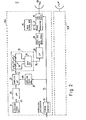
- Referring to Figs. 2 and 3, a substation indicated by 12A in Fig. 2 is for use in a time division multiple access system according to an embodiment of this invention and comprises a
timing controller 15 responsive to the down-link succession for extracting the interval sequence SA assigned to the substation 12A, as depicted at SA in Fig. 1. The interval sequence SA is specified by a timing pulse sequence TS including timing pulses Al and A2 produced by thetiming controller 15. Preferably, each timing pulse A1-A2 lasts during each interval assigned to the substation 12A. - The interval sequence SA is received at the
central station 11 as the up-link succession UP formed by combination with the remaining N - 1 interval sequences labelled B-H, as shown atop of Fig. 3. Thus, each interval sequence, such as SA, is in timed relation to the up-link succession UP. - In Fig. 2, the substation 12A comprises a
main signal generator 16 for generating a main signal M, such as a data signal, having an inphase component and a quadrature component. Such a main signal M is supplied to aphase modulator 17 to be subjected to four-phase phase modulation. Responsive to the timing pulse sequences A1-A2, an on-offgate 18 produces a phase modulated the main signal as the up-link burst BA during/presence of each timing pulse A1-A2. - Further referring to Fig. 2, the timing pulse sequence TS is supplied to a
sampling pulse generator 20 to produce a succession of sampling pulses SM at a predetermined sample period TS. Each of the sampling pulses SM has a sampling pulse width designated by ΔTS. A first one of the sampling pulses SM shown at the leftmost end thereof is delayed somewhat from the leading edge of the timing pulse A1. This delay will be described later. - The substation 12A further comprises.a
subsidiary signal generator 21 for producing a subsidiary signal SY. As shown in Fig. 3, the subsidiary signal SY is given in the form of an analog signal. Let the analog signal mainly fall within an audio frequency band. - Such a subsidiary signal SY is supplied to a sampling having been
circuit 22 after/restricted to a frequency band between 0 and 3 kHz by alow pass filter 23. Thelow pass filter 23 serves to protect any error signal from occurring on sampling the subsidiary signal SY. - As readily understood from the above, a repetition frequency and the sampling period TS of the sampling pulse sequence is higher and shorter than 6 kHz and 167 microseconds, respectively, to sample the subsidiary signal SY between 0 and 3 kHz.
- Herein, let the frame period TF be equal to 450 microseconds. Under these circumstances, the subsidiary signal SY may be sampled at the sampling period TS of 150 microseconds. In other words, three of the sampling pulses appear within every frame period TF, as illustrated in Fig. 3.
- For convenience of the later description, the number of the sampling pulses produced in each frame period is assumed to be represented by a natural number M. In the illustrated system, the natural number is equal to three.
- Anyway, the
sampling circuit 22 produces a succession of sampled pulses representative of the subsidiary signal SY which is to be transmitted from the substation 12A. Each of the sampled pulses is indicated at P in the subsidiary signal SY and successively numbered from the leftmost one as P1'-P2'.... - The sampled pulses P are successively sent to a
delay circuit 25 for delaying the sampled pulse succession P until appearance of the next following timing pulse A2 to produce a delayed pulse succession DL including-delayed sampled pulses equal in number to the natural number M during presence of the next following timing pulse A2. - More particularly, the
delay circuit 25 comprises adelay portion 26 comprising a plurality of unit delay circuits which are connected in cascade and each of which has a unit delay time represented by TS-ΔTS. Thus, the unit delay time is shorter than the sampling period TS by the sampling pulse width ΔTS. In the illustrateddelay portion 26, the number of the unit delay circuits is equal to M - 1, namely, two. - In this
delay portion 26, a first one of the sampled the pulses (depicted at P1) does not appear during/presence of the next following timing pulse A2 even when the first sampled pulse P1 is delayed by thedelay portion 26. Instead, the first sampled the pulse P1 is produced during/presence of the current timing pulse A1 without a delay together with two sampled pulses (not shown) sampled in the preceding frame period. - Second and third ones of the sampled pulses P2 and P appear as second and third ones of the delayed pulses DL during presence of the next following timing pulse A2. With the above-mentioned
delay portion 26, the second delayed pulse P2 is at first produced from thedelay portion 26 and is followed by the third delayed pulse P3 during the presence of the timing pulse A28 After production of the third delayed pulses P39 a fourth one of the sampled pulses P4 appears without a delay. _Thus, three of the sampled signals are collected or gathered by a gate circuit 27 connected to the respective unit delay circuits within a single timing pulse, such as A28 - From this fact, it is readily understood that the preceding sampled pulse, such as P2, is delayed longer than the following sampling pulse P3 by the
delay portion 26 and is produced from thedelay portion 26 earlier than the latter. This is because each of the delay unit circuits has the unit delay time shorter than the sampling period and is connected in cascade relative to each other. In any event, the illustrateddelay circuit 25 serves to give each of the sampled pulses successively increasing delays and to derive or gather a group of M delayed pulses from the delayed pulse succession in each of the intervals assigned to the substation 12A. - It should be recollected that the sampling pulse corresponding to the first sampled pulse P1 is delayed relative to the leading edge of the timing pulse Al. The delay between the leading edge and the sampling pulse in question gives time for arranging two of the delayed pulses each having the pulse width of ΔTS.
- The pulse width ΔTS should be determined in consideration of the intervals, namely, time slots which are assigned to the respective substations and which may vary in length of time. In the case of the shortest one of the intervals, the sampling pulse width ΔTS should be less than one third of the shortest interval in the illustrated substation 12A on condition that each substation samples each of the subsidiary signals at the same sampling period by the use of sampling pulses having the same sampling pulse widths.
- The delayed pulses DL, namely, gathered sampled pulses are sent from the gate circuit 27 through an additional
low pass filter 28 to alocal oscillator 29, with those harmonic components removed from the delayed pulses DL by the additionallow pass filter 28. Thelocal oscillator 29 generates a local oscillation signal of a preselected frequency. The local oscillation signal is frequency modulated by the delayed pulses DL supplied through the additionallow pass filter 28. Such frequency modulation is possible by the use of a well-known element, such as a diode, included in thelocal oscillator 29. It should be noted here that a modulation index is considerably low in the frequency modulation. For example, a frequency deviation may be about 7 kHz rms in the frequency modulation. In other words, shallow frequency modulation is carried out by the element. Such shallow frequency modulation serves to prevent the main signal M from being adversely affected by transmission of the subsidiary signal SY. - As a result, a frequency modulated local oscillation signal is supplied to the
phase modulator 17 to be subjected to four-phase phase modulation in a manner described before. A combination of thelocal oscillator 29, thephase modulator 17, and the on-off gate 28 is operable in response to the main signal M and the delayed pulse sequence to transmit the up-link burst BA to the central station in the intervals which are assigned to the substation 12A and specified by the timing pulse sequence TS. Therefore, the main and subsidiary signal combination appears as the combination of the main signal M and the delayed pulse sequence DL in the illustrated substation 12A. Thus, the up-link burst BA carries the main signal M and the delayed pulse sequence DL. The up-link bursts BA are intermittently produced as a sequence during the intervals appearing at every frame period. - The other substations (represented by the
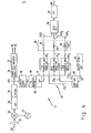
substation 12B in Fig. 2) are similar in structure and operation to the substation 12A. The resultant up-link sequences are sent from the remaining substations to thecentral station 11 in the interval sequences assigned to the remaining substations. The up-link succession UP is thus formed by arranging the respective up-link burst sequences, as shown atop of Fig. 3. - Referring to Fig. 4 afresh and Fig. 3 again, the
central station 11 for use in combination with the substations as shown in Fig. 2 receives the up-link succession UP of the up-link bursts- illustrated with reference to Fig. 3. In each of the frame period, N successive up-link bursts are received at thecentral station 11. Thecentral station 11 separates the up-link bursts of the succession UP into N up-link burst sequences transmitted from the respective substations. Each up-link burst sequence includes the up-link bursts appearing at every frame period. For brevity of description, operation of thecentral station 11 will mainly with respect to the processing of be described / . the up-link burst transmitted from the substation 12A-but"the similar operation is carried out in the other substations in order to process the up-link burst sequences transmitted from the other substations. - In Fig. 4, the up-link-succession UP is supplied through an
antenna 31 to amixer 32 coupled to a central stationlocal oscillator 33 to be converted into a reception intermediate frequency signal (abbreviated to an IF signal). The IF signal is sent from themixer 32 through aband pass filter 34 to alimiter 35 to be wave-shaped. A wave shaped signal WS is delivered from thelimiter 35 to aphase demodulator 36 in which the wave shaped signal WS is subjected to four-phase phase demodulation. In consequence of the phase demodulation, a main signal component is supplied as a reproduction of the main signal from thephase demodulator 36 to adecoder 37. Thedecoder 37 decodes the reproduction into a pair of decoded signals IC and QC corresponding to the inphase and the quadrature components of the main signal M. - Further referring to Fig. 4, the wave-shaped signal WS is also delivered from the
limiter 35 to acarrier signal circuit 38. Thecarrier signal circuit 38 serves to derive a carrier signal component of an intermediate frequency band from the wave-shaped signal WS and to eliminate the main signal component. The carrier signal component is subjected to frequency modulation by the delayed pulse sequences. - Responsive to the carrier signal component, a frequency- modulation detector (abbreviated as FM detector) 39 detects the delayed pulse sequence to produce discrete groups (indicated by DG in_Fig. 3) of delayed pulse reproductions representative of the respective delayed pulses produced in the
substation 12B. Each discrete group DG is compressed or gathered in each of the intervals assigned to the up-link bursts for the substation 12A. - The delayed pulse reproductions indicated by DG are sent from the
FM detector 39 to a rearrangingcircuit 40 as will presently be described after passing through alow pass filter 41 having a pass band of about 1/dTS. Thelow pass filter 41 lends itself to improvement of a signal to noise ratio of the delayed pulse reproductions DG. - The rearranging
circuit 40 is coupled to amaster clock generator 43 for producing a succession of master clocks MC.-The master clocks MC specify the intervals assigned to the respective up-link bursts. Therefore, themaster clock generator 43 is operable to extract a specific one of the up-link burst sequences that is transmitted from the substation 12A. The rearrangingcircuit 40 comprises asampling pulse generator 45 responsive to the master clock succession MC for producing three streams CS1, CS2, and CS3 of sampling pulses with reference to each of the master clocks MC. In other words, the number of the sampling pulse streams is equal to the natural number M described in conjunction with Fig. 2. The sampling pulse streams CS1, CS2, and CS3 are referred to as first, second, and third pulse streams, respectively. The second pulse stream CS2 is delayed relative to the first pulse stream CS1 by the delay time equal to the sampling pulse width ΔTS described in connection with Fig. 2 and is followed by the third pulse stream CS3 with the same delay time appearing after the second pulse stream CS2. - The first through third pulse streams CS1 to CS3 are produced by the
sampling pulse generator 45 in response to each of the master clocks MC. As a result, three pulses appear during every one of the up-link bursts, as exemplified with respect to the up-link bursts BA assigned to the substation 12A. This implies that, during the next following up-link burst, three pulses which belong to the respective pulse streams CS1 to CS3 are produced by thesampling pulse generator 45. - The first pulse stream CS1 is delivered to a first sample-and-hold circuit 46 in synchronism with a first one of the discrete groups DG. Likewise, the second and the third pulse streams CS2 and CS3 are delivered to second and third sample-and-hold circuits 47 and 48 in timed relation to second and third ones of the discrete groups DG, respectively. As a result, the discrete groups DG of the delayed pulse reproductions are separated into first, second, and third reproduced pulse sequences PL1, PL2, and PL3 by the first through third sample-and-hold circuits 46 to 48, respectively, as shown in Fig. 3.
- The rearranging
circuit 40 further comprises a central station delay circuit 50 responsive to the first through third reproduced pulse sequences PL1, PL2, and PL3 for giving successively increasing delays thereto to produce a succession of sampled pulse reproductions representative of the sampled pulses sampled in the substation 12A. Such a sampled pulse reproduction succession represents the subsidiary signal transmitted from the substation 12A. - More particularly, the delay circuit 50 comprises a
first delay element 51 having no substantial delay and second andthird delay elements 52 and 53 having delays equal to TS - ΔTS and 2(TS - ΔTS), respectively. Inasmuch as the first reproduced pulse sequence PL1 is given to thefirst delay element 51, each pulse of the sequence PL1 appears as a first output signal OUT1 without any substantial delay. - It is to be noted here that each pulse of the second reproduced pulse sequence PL2 is delayed relative to that of the first reproduced pulse sequence PL1 by ΔTS while each pulse of the third reproduced pulse sequence PL3 is delayed by 2.ΔTS.
- When each pulse of the second reproduced pulse sequence PL2 is subjected to the delay of TS - ΔTS by the second delay element 52, it appears as second output signal OUT2 at a time point one sampling-period TS after appearance of the first reproduced pulse PL1.
- Likewise, the
third delay element 53 produces a third output signal sequence OUT3 at another time point two sampling period 2TS after production of the first output signal sequence OUT1 because of the delay of 2(TS - ΔTS) in thethird delay element 53. - The first through third output signals OUT to OUT3 are supplied to a
gate circuit 56 as the succession of the sampled pulse reproductions. Thus, the discrete groups DG compressed are in each up-link burst BA / rearranged into the sampled pulse reproductions produced at every sampling period TS. - Responsive to the succession of the sampled pulse reproduction, a
low pass filter 57 desamples or converts the succession into an analog signal AN representative of a reproduction of the subsidiary signal transmitted from the substation 12A, as indicated by a real line. - The above-mentioned rearrangement results in concurrent reproductions of the subsidiary signals transmitted from the other substations, as depicted at a broken line and a dot-and-dash line in AN. Such concurrent reproductions are effective for transmission of the order-wire signals from the substations.
- In the time division multiple access system according to the first embodiment of this invention, it has been assumed that the sampling period TS is equal to one third of the frame period TF and the natural number M is equal to three. However, the sampling period TS may not be shorter than the frame period TF. In order-to precisely sample the subsidiary signal, it is also assumed that the natural number M is equal to unity even when the subsidiary signal is satisfactorily sampled by a sampling pulse having a sampling period TS longer than the frame period TF. In this case, the sampling period TS becomes equal to the frame period TF. Accordingly, a single one of the sampling pulses SM may appear within each sampling period TF. If the single sampling pulse is produced within each timing pulse, the
delay circuit 25 is unnecessary in each substation because the sampled pulse may be sent to thecentral station 11 without any delay, as in the case of the first and the fourth sampled pulses P1 and P4. This means that thecentral station 11 needs no delay circuit 50 either. On the other hand, if the single sampling pulse is shifted or displaced from a current up-link burst, as illustrated at the second or the third sampled pulse P2 or P39 each sampled pulse should be delayed until appearance of the next following up-link burst corresponding to the current up-link burst. Consequently, each substation is provided with a delay circuit, such as 25. However, the central station does not always need a delay circuit, such as 50. - Taking the above into consideration, it will be seen that the
delay circuit 25 in each substation is operable to locate or arrange at least one sampled pulse in each up-link burst. In this sense, thedelay circuit 25 and/or the gate circuit 27 may be called a locating circuit for locating at least one sampled pulse in a preselected interval of the interval.sequence assigned to each substation. - While this invention has thus far been described in conjunction with a few embodiments thereof, it is readily possible for those skilled in the art to put this invention into practice in various manners. For example, the leading sampled pulse, such as P1 or P4, in each frame may also be delayed until the next following timing pulse A2 by using a similar unit delay circuit. This structure is especially effective when the leading sampled the pulse is not produced during/presence of each timing pulse A or A 2.
Claims (5)
Applications Claiming Priority (2)
| Application Number | Priority Date | Filing Date | Title |
|---|---|---|---|
| JP56105108A JPS587946A (en) | 1981-07-07 | 1981-07-07 | Transmission system for announce call order telephone signal in time-sharing multi-direction multiplex communication network |
| JP105108/81 | 1981-07-07 |
Publications (3)
| Publication Number | Publication Date |
|---|---|
| EP0069970A2 true EP0069970A2 (en) | 1983-01-19 |
| EP0069970A3 EP0069970A3 (en) | 1983-03-16 |
| EP0069970B1 EP0069970B1 (en) | 1985-05-22 |
Family
ID=14398650
Family Applications (1)
| Application Number | Title | Priority Date | Filing Date |
|---|---|---|---|
| EP82106029A Expired EP0069970B1 (en) | 1981-07-07 | 1982-07-06 | Time division multiple access system for transmitting an analog signal by the use of bursts without substantial interruption |
Country Status (5)
| Country | Link |
|---|---|
| US (1) | US4488296A (en) |
| EP (1) | EP0069970B1 (en) |
| JP (1) | JPS587946A (en) |
| CA (1) | CA1181539A (en) |
| DE (1) | DE3263743D1 (en) |
Cited By (1)
| Publication number | Priority date | Publication date | Assignee | Title |
|---|---|---|---|---|
| GB2285725A (en) * | 1994-01-13 | 1995-07-19 | Fujitsu Ltd | Data burst transfer |
Families Citing this family (9)
| Publication number | Priority date | Publication date | Assignee | Title |
|---|---|---|---|---|
| AU577739B2 (en) * | 1984-01-21 | 1988-09-29 | Nec Corporation | Tdma station relief system |
| US4688216A (en) * | 1984-05-10 | 1987-08-18 | Nec Corporation | Station relief arrangement for use in relieving operation of a reference station in a TDMA network without reduction of frame availability |
| US4852090A (en) * | 1987-02-02 | 1989-07-25 | Motorola, Inc. | TDMA communications system with adaptive equalization |
| US6468805B1 (en) | 1990-10-10 | 2002-10-22 | Chimera Research And Chemical Inc. | Automated analyzer testing of urine for presence of a pH abnormality |
| US5801060A (en) * | 1990-10-10 | 1998-09-01 | Chimera Research & Chemical, Inc. | Method of using automated analyzer testing of urine for presence of a pH abnormality with single reagent indicator |
| US5392460A (en) * | 1993-04-23 | 1995-02-21 | Nokia Mobile Phones Ltd. | Dual mode radiotelephone terminal selectively operable for frequency modulated or phase modulated operation |
| CA2154825A1 (en) * | 1994-09-09 | 1996-03-10 | Lars H. Mucke | Dual mode radiotelephone modulator |
| GB2302484B (en) * | 1995-06-17 | 1999-08-04 | Northern Telecom Ltd | Optical tdm transmission system |
| JPH09331291A (en) * | 1996-04-10 | 1997-12-22 | Oki Electric Ind Co Ltd | Radio communication system and radio communication equipment |
Citations (2)
| Publication number | Priority date | Publication date | Assignee | Title |
|---|---|---|---|---|
| US3781822A (en) * | 1972-08-09 | 1973-12-25 | Bell Telephone Labor Inc | Data rate-changing and reordering circuits |
| US3939407A (en) * | 1973-12-03 | 1976-02-17 | Raytheon Company | Plural channel communications system |
Family Cites Families (7)
| Publication number | Priority date | Publication date | Assignee | Title |
|---|---|---|---|---|
| US3870828A (en) * | 1973-09-06 | 1975-03-11 | Paradyne Corp | Superimposed binary signal |
| US4168398A (en) * | 1976-11-10 | 1979-09-18 | Nippon Electric Co., Ltd. | Initial acquisition signal detection system for TDMA satellite communication |
| US4079203A (en) * | 1977-03-30 | 1978-03-14 | The United States Of America As Represented By The Secretary Of The Army | Method and apparatus for transmitting auxiliary channel over digital communications system |
| US4252999A (en) * | 1978-10-04 | 1981-02-24 | Bell Telephone Laboratories, Incorporated | Signaling and ranging technique for a TDMA satellite communication system |
| US4287588A (en) * | 1979-04-12 | 1981-09-01 | The United States Of America As Represented By The Secretary Of The Army | Multiple access, time-division multiplex, satellite communications system |
| US4387460A (en) * | 1979-07-23 | 1983-06-07 | Societe Anonyme De Tele-Communication | Supplementary information transmitting arrangement for a digital data transmission system |
| US4363127A (en) * | 1981-01-12 | 1982-12-07 | Ford Aerospace & Communications Corporation | Line signaling apparatus and techniques for digital data links |
-
1981
- 1981-07-07 JP JP56105108A patent/JPS587946A/en active Granted
-
1982
- 1982-07-06 US US06/395,113 patent/US4488296A/en not_active Expired - Lifetime
- 1982-07-06 CA CA000406672A patent/CA1181539A/en not_active Expired
- 1982-07-06 DE DE8282106029T patent/DE3263743D1/en not_active Expired
- 1982-07-06 EP EP82106029A patent/EP0069970B1/en not_active Expired
Patent Citations (2)
| Publication number | Priority date | Publication date | Assignee | Title |
|---|---|---|---|---|
| US3781822A (en) * | 1972-08-09 | 1973-12-25 | Bell Telephone Labor Inc | Data rate-changing and reordering circuits |
| US3939407A (en) * | 1973-12-03 | 1976-02-17 | Raytheon Company | Plural channel communications system |
Non-Patent Citations (2)
| Title |
|---|
| ELECTRONIC DESIGN, vol. 27, no. 8, 12th April 1979, pages 118-121, Rochelle Park (USA); B. WARNER, Jr.: "Fast LSI memories cram more information into satellite-communications bands". * |
| NEC RESEARCH & DEVELOPMENT, no. 54, July 1979, pages 1-12, Tokyo (JP); T. UCHINO et al.: "Development of TDMA satellite communication equipment". * |
Cited By (3)
| Publication number | Priority date | Publication date | Assignee | Title |
|---|---|---|---|---|
| GB2285725A (en) * | 1994-01-13 | 1995-07-19 | Fujitsu Ltd | Data burst transfer |
| US5477533A (en) * | 1994-01-13 | 1995-12-19 | Fujitsu Limited | Burst transfer device and burst transfer system |
| GB2285725B (en) * | 1994-01-13 | 1998-04-08 | Fujitsu Ltd | Burst transfer device and burst transfer system |
Also Published As
| Publication number | Publication date |
|---|---|
| US4488296A (en) | 1984-12-11 |
| EP0069970A3 (en) | 1983-03-16 |
| JPS587946A (en) | 1983-01-17 |
| JPS6345143B2 (en) | 1988-09-08 |
| CA1181539A (en) | 1985-01-22 |
| EP0069970B1 (en) | 1985-05-22 |
| DE3263743D1 (en) | 1985-06-27 |
Similar Documents
| Publication | Publication Date | Title |
|---|---|---|
| US5790784A (en) | Network for time synchronizing a digital information processing system with received digital information | |
| CA2194394C (en) | Control symbol and data symbol guard intervals with different time lengths in cofdm transmission frames | |
| US3689841A (en) | Communication system for eliminating time delay effects when used in a multipath transmission medium | |
| US4470141A (en) | Multi-direction time division multiplex communication system | |
| US4488296A (en) | Time division multiple access system for transmitting an analog signal by the use of bursts without substantial interruption | |
| US4330859A (en) | Automatic gain control circuit in multi-direction time division multiplex communication system | |
| DE69832746T2 (en) | Access system for sectored radio networks | |
| CA2077269A1 (en) | Time synchronization of a receiver in a digital radio telephone system | |
| US3484693A (en) | Frequency shifted sliding tone sampled data communication system | |
| SE7500482L (en) | ||
| CA2021847A1 (en) | Radiotelephone system | |
| US4585998A (en) | Method and device for coherent demodulation of a digitally modulated carrier | |
| JPS5926136B2 (en) | clock regeneration circuit | |
| EP0180238B1 (en) | Digital radio communication system | |
| US4719623A (en) | Method of receiving time multiplexed signals together with energy requirements of receiver over a multiplex signal transmission path | |
| US4625318A (en) | Frequency modulated message transmission | |
| GB1572856A (en) | Multiphase receiver | |
| JPS6455917A (en) | Control method for rds receiver | |
| Alberty et al. | Digital on-board multicarrier demodulator for mobile satellite communications | |
| DE2723960C3 (en) | HF transmission method for digitized, encrypted voice signals in time division multiplex with an FSK modem | |
| SU1277872A1 (en) | Device for reception of phase-manipulated signals | |
| JPS6370631A (en) | Time division multiple access communication system | |
| JPS6326573B2 (en) | ||
| Campbell et al. | Time division radio relay synchronizing system using different sync code words for in sync and out of sync conditions Patent | |
| JPS639695B2 (en) |
Legal Events
| Date | Code | Title | Description |
|---|---|---|---|
| PUAI | Public reference made under article 153(3) epc to a published international application that has entered the european phase |
Free format text: ORIGINAL CODE: 0009012 |
|
| PUAL | Search report despatched |
Free format text: ORIGINAL CODE: 0009013 |
|
| AK | Designated contracting states |
Designated state(s): DE FR GB |
|
| AK | Designated contracting states |
Designated state(s): DE FR GB |
|
| 17P | Request for examination filed |
Effective date: 19830309 |
|
| RAP1 | Party data changed (applicant data changed or rights of an application transferred) |
Owner name: NEC CORPORATION |
|
| GRAA | (expected) grant |
Free format text: ORIGINAL CODE: 0009210 |
|
| AK | Designated contracting states |
Designated state(s): DE FR GB |
|
| REF | Corresponds to: |
Ref document number: 3263743 Country of ref document: DE Date of ref document: 19850627 |
|
| ET | Fr: translation filed | ||
| PLBE | No opposition filed within time limit |
Free format text: ORIGINAL CODE: 0009261 |
|
| STAA | Information on the status of an ep patent application or granted ep patent |
Free format text: STATUS: NO OPPOSITION FILED WITHIN TIME LIMIT |
|
| 26N | No opposition filed | ||
| PGFP | Annual fee paid to national office [announced via postgrant information from national office to epo] |
Ref country code: GB Payment date: 19950630 Year of fee payment: 14 |
|
| PGFP | Annual fee paid to national office [announced via postgrant information from national office to epo] |
Ref country code: FR Payment date: 19950725 Year of fee payment: 14 |
|
| PGFP | Annual fee paid to national office [announced via postgrant information from national office to epo] |
Ref country code: DE Payment date: 19950929 Year of fee payment: 14 |
|
| PG25 | Lapsed in a contracting state [announced via postgrant information from national office to epo] |
Ref country code: GB Effective date: 19960706 |
|
| GBPC | Gb: european patent ceased through non-payment of renewal fee |
Effective date: 19960706 |
|
| PG25 | Lapsed in a contracting state [announced via postgrant information from national office to epo] |
Ref country code: FR Effective date: 19970328 |
|
| PG25 | Lapsed in a contracting state [announced via postgrant information from national office to epo] |
Ref country code: DE Effective date: 19970402 |
|
| REG | Reference to a national code |
Ref country code: FR Ref legal event code: ST |