EP0069987A2 - Laser beam scanning mechanism - Google Patents
Laser beam scanning mechanism Download PDFInfo
- Publication number
- EP0069987A2 EP0069987A2 EP82106091A EP82106091A EP0069987A2 EP 0069987 A2 EP0069987 A2 EP 0069987A2 EP 82106091 A EP82106091 A EP 82106091A EP 82106091 A EP82106091 A EP 82106091A EP 0069987 A2 EP0069987 A2 EP 0069987A2
- Authority
- EP
- European Patent Office
- Prior art keywords
- mirror
- joystick
- concave surface
- mirror holder
- scanning mechanism
- Prior art date
- Legal status (The legal status is an assumption and is not a legal conclusion. Google has not performed a legal analysis and makes no representation as to the accuracy of the status listed.)
- Granted
Links
Images

Classifications
-
- A—HUMAN NECESSITIES
- A61—MEDICAL OR VETERINARY SCIENCE; HYGIENE
- A61B—DIAGNOSIS; SURGERY; IDENTIFICATION
- A61B18/00—Surgical instruments, devices or methods for transferring non-mechanical forms of energy to or from the body
- A61B18/18—Surgical instruments, devices or methods for transferring non-mechanical forms of energy to or from the body by applying electromagnetic radiation, e.g. microwaves
- A61B18/20—Surgical instruments, devices or methods for transferring non-mechanical forms of energy to or from the body by applying electromagnetic radiation, e.g. microwaves using laser
-
- G—PHYSICS
- G02—OPTICS
- G02B—OPTICAL ELEMENTS, SYSTEMS OR APPARATUS
- G02B26/00—Optical devices or arrangements for the control of light using movable or deformable optical elements
- G02B26/08—Optical devices or arrangements for the control of light using movable or deformable optical elements for controlling the direction of light
- G02B26/0816—Optical devices or arrangements for the control of light using movable or deformable optical elements for controlling the direction of light by means of one or more reflecting elements
-
- A—HUMAN NECESSITIES
- A61—MEDICAL OR VETERINARY SCIENCE; HYGIENE
- A61B—DIAGNOSIS; SURGERY; IDENTIFICATION
- A61B34/00—Computer-aided surgery; Manipulators or robots specially adapted for use in surgery
- A61B34/70—Manipulators specially adapted for use in surgery
- A61B34/74—Manipulators with manual electric input means
- A61B2034/742—Joysticks
Definitions
- This invention relates to a laser beam scanning mechanism in which, in the operation of a laser knife under a microscope, a joystick is operated to change the laser irradiation position.
- the operator shifts the point irradiated with the laser beam by operating a joystick back and forth or right and left while observing the vital tissues through a microscope.
- the laser irradiation position is determined by the inclination angle of a mirror.
- a mechanism for controlling the motion of the stick to control the inclination of the mirror has been disclosed by the specificationsof Japanese Patent Application Laid Open Nos. 111295/1977 and 106144/1980, for example.
- a mirror for reflecting the laser beam is supported by a horizontal shaft, and a stand including the horizontal shaft is supported by a vertical shaft.
- Servo motors are coupled to the horizontal shaft and the vertical shaft, respectively, so that the mirror is turnable about both the horizontal shaft and the vertical shaft.
- the horizontal movement and the lateral movement of the joystick operate respective potentiometers.
- the rotational displacements of the servo motors are detected, to change the resistance of other potentiometers.
- the two sets of potentiometers form two bridge circuits, so that the servo motors are turned in one direction or the other in response to the movements of the stick, to-thereby change the inclination angle of the mirror.
- This mechanism is similar to the above-described mechanism in that the mirror is supported by a horizontal shaft, and a U-shaped stand including the horizontal shaft is supported by a vertical shaft, so that the mirror can turn about these shafts.
- this mechanism instead of the servo motors and the potentiometers, several levers are used in combination so that the horizontal and vertical motions of the joystick are transformed into rotational displacements around the vertical and horizontal shafts, respectively.
- Such a gimbal mechanism needs no servo motor; however, it requires two orthogonal rotary shafts and several levers in combination. Therefore, the housing of the microscope is necessarily bulky.
- the mechanism suffers from a difficulty in that, although two independent "lever" systems are required in order to transmit the horizontal and vertical movements to the mirror, the inclination of the mirror is not made independent. For instance, when the rotational displacements of the mirror about the horizontal shaft are different, and the stick is moved to the right and to the left with one and the same amplitude, the amounts of the displacement of the mirror about the vertical shaft are different from one another.
- the laser beam irradiation position is shifted by a value which is obtained by multiplying the angle of deflection by the distance between the mirror and the tissue being operated upon.
- the reflecting mirror is rotatably supported by two orthogonal axes. Therefore, it has been impossible to reduce the size of the microscope's bulky housing.
- An object of this invention is thus to provide a laser beam scanning mechanism in which the movement of the joystick is purely mechanically converted into a change in the angle of inclination of the mirror, wherein the construction is simple, but free from play, the conversion ratio in the horizontal direction is equal to that in the vertical direction, and wherein the mirror can be finely displaced.
- a concave surface is formed in the rear wall of a mirror holder supported at the fulcrum which is the center thereof, the end of the joystick is in contact with the concave surface, and the distance (1) between the end of the stick and the fulcrum of the stick is made different from the radius of curvature (r) of the concave surface, so that the angle of inclination of the mirror is changed according to the movement of the joystick.
- Fig. 1 is a diagrammatic section view showing one example of a laser beam scanning mechanism according to the invention.
- the laser beam scanning mechanism is incorporated in an adaptor 2 secured to the lower end of a microscope body 1.
- An adaptor body 3 is in the form of a box having an opening 4 in the lower surface.
- a supporting plate 5 extends obliquely from the near wall of the adaptor body 3.
- a small fulcrum ball 6 is provided on the supporting plate 5.
- At least three bolts 7 and at least three springs 8 are arranged rotationally symmetrically about the fulcrum ball 6, so that a mirror holder 9 can be tilted slightly about the fulcrum ball 6.
- a mirror 10 for reflecting the laser beam is provided in front of the mirror holder 9.
- a joystick 12 is provided through a spherical bearing 11 on an upper wall of the adaptor body 3 in such a manner that it is horizontally and vertically movable.
- the laser beam reflected by the mirror surface 13 is applied to a desired part of the tissue 14. That part of the tissue 14 thus irradiated can be-observed through an eye piece 15.
- the microscope optical axis 16 extends from the tissue 14 through the opening 4 to the eye piece 15.
- An incident laser beam 17 is maintained unchanged in direction and position, while the reflected laser beam 18 undergoes angular displacement as the angle of the mirror is changed.
- a concave surface 19 (Fig. 3) having a radius of curvature r is formed in the rear surface of the mirror holder 9.
- the joystick 12 is rockable with one end thereof being in contact with the concave surface 19. If the effective length 1 of the stick (which is the distance between the spherical bearing 11 andthe end of the stick 12) is different from the radius of curvature r of the concave surface, then the angle of inclination of the mirror holder 9 can be changed by operating the stick.
- the mirror When the joystick 12 is moved through an angle a, the mirror is tilted through an angle ⁇ . In this case, the reflected laser beam 18 is swung through an angle 2 ⁇ .
- FIG. 2 and 3 One example of an elastic supporting mechanism for the mirror holder 9 and the supporting plate 5 are as shown in Figs. 2 and 3.
- the mirror holder 9 and the mirror 10 are assembled into one unit which is substantially in the form of a quadrangular prism.
- the mirror 10 is provided at the front surface of the quadrangular prism, and the concave surface 19 is formed in the rear surface thereof.
- the supporting plate 5 is inserted between the front and rear surfaces of the quandrangular prism, i.e., between the mirror 10 and the concave surface 19.
- the bolts 7 are provided rotationally symmetrically about the fulcrum ball 6 of the supporting plate 5.
- a spring hole 20 is provided for each bolt. More specifically, the spring hole is bored in the supporting plate 5 at the position of each bolt 7.
- the spring 8 is inserted into the spring hole 20 in such a manner that it is compressed between the bolt head 22 and the step 21 in the spring hole 20.
- the end portion of the bolt 7 is threadably engaged with a threaded hole 24 in the mirror holder 9 through a throughhole 23 in the supporting plate S.
- the mirror holder 9 is pulled towards the supporting plate 5 by means of the springs 8 and the bolts 7; however, there is a gap 25 between the mirror holder 9 and the supporting plate 5 because the fulcrum ball 6 is set therebetween.
- the supporting plate 5 When the end of the stick 12 is in contact with the center C of the rear surface immediately behind the fulcrum ball 6, the supporting plate 5 is parallel with the surface of the mirror holder 9.
- the mirror holder 9 When, on the other hand, the end of the stick 12 pushes upon a point other than the center C, the mirror holder 9 is tilted because the radius of curvature r of the concave surface is different from the effective length A of the joystick.
- Fig. 4 outlines the arrangement of the stick 12 and the concave surface 19. The relation between the angle of inclination a of the stick and the angle of inclination ⁇ of the mirror will be described with reference to Fig. 4.
- reference numeral A designates the fulcrum of the stick 12, which corresponds to the center of the spherical bearing 11.
- An arc m with a radius 1 and with the point A as its center is the locus of the end of the stick 12.
- the center C of the arc m is the fulcrum of the concave surface 19.
- Fig. 4 is for the case where the joystick's effective length 1 is larger than the radius of curvature r of the concave surface (l > r).
- the locus of the center of the concave surface is a broken line DD'.
- the angle of inclination of the concave surface is / D'CD
- Fig. 5 is for the case l ⁇ r.
- the point A is the stick fulcrum
- the points D or D' is the center of the concave surface
- the straight line D'AH is the perpendicular bisector of the segment BC.
- the angle a should be defined toward the same side as the angle a. In Fig. 5, the angle a is measured towards the left- handed side from the center line AC,' and therefore the angle a has the positive sign. On the other hand, as the angle ⁇ is measured towards the right-handed side, the angle ⁇ is negative.
- the reduction ratio of the angle variation (R) is as follows:
- the motion of the mirror can be more finely adjusted.
- Fig. 6 is a graphical representation indicating the angles of inclination a of the stick and the angles of inclination ⁇ of the mirror with a as the parameter.
- eight values 0.8, 0.85, 0.9, 0.95, 1.05, 1.1, 1.15, and 1.2 are selected for the parameter a.
- the angle of inclination a of the joystick is up to 0.6 radian (34.4°). It can be understood that, in this range, B changes linearly with a.
- the angle of inclination of the mirror has been described above.
- the angle of deflection of the reflected laser beam is 2 ⁇ , because it is twice the inclination angle of the mirror.
- the ratio of scanning position displacement with respect to the stick operation can be defined as follows:
- the mirror is considerably smoothly movable, and the horizontal reduction ratio is in agreement with the vertical reduction ratio at all times.
- a rubber member 26 may be interposed between the supporting plate 5 and the wall of the mirror holder opposite the wall in which the concave surface has been formed. (Fig. 7).
- a protrusion 27 and a recess 28 for receiving the protrusion 27 may be provided for the supporting plate 5 and the mirror holder 9, respectively, or vice versa.
- the arrangement of the elastic supporting mechanism is optional.
- the mirror 10 may be bonded to one surface 29 thereof.
- the concave surface 19 and the mirror 10 are provided on the opposite walls of the mirror holder, respectively; however, if the joystick mouting position is changed, then the concave surface 19 and the mirror 10 may_be provided on adjacent walls of the mirror holder.
- the fulcrum of the mirror holder must be near the center of the concave surface. With the distance e between the center of the fulcrum ball 6 and the concave surface center C as shown in Fig. 3, it is unnecessary to add serious correcting terms to equations (6) and (8).
- the value a may be larger than one or may be smaller than one.
- the value a must be larger than one (a > 1) so that, when the stick 12 is moved to the right-handed side, the irradiation point x is moved in the same direction, because the parameters a and Shave the same sign (according to expression (8)).
- the value a be larger than one (1), because the positional relationship can be known by intuition.
- the direction of the movement of the joystick is opposite to the direction of movement of the irradiation point x.
- the value a be smaller than one (a ⁇ 1).
Abstract
Description
- This invention relates to a laser beam scanning mechanism in which, in the operation of a laser knife under a microscope, a joystick is operated to change the laser irradiation position.
- In a surgical operation using a laser knife, the operator shifts the point irradiated with the laser beam by operating a joystick back and forth or right and left while observing the vital tissues through a microscope.
- The laser irradiation position is determined by the inclination angle of a mirror. A mechanism for controlling the motion of the stick to control the inclination of the mirror has been disclosed by the specificationsof Japanese Patent Application Laid Open Nos. 111295/1977 and 106144/1980, for example.
- In the former mechanism, a mirror for reflecting the laser beam is supported by a horizontal shaft, and a stand including the horizontal shaft is supported by a vertical shaft. Servo motors are coupled to the horizontal shaft and the vertical shaft, respectively, so that the mirror is turnable about both the horizontal shaft and the vertical shaft. The horizontal movement and the lateral movement of the joystick operate respective potentiometers. The rotational displacements of the servo motors are detected, to change the resistance of other potentiometers. The two sets of potentiometers form two bridge circuits, so that the servo motors are turned in one direction or the other in response to the movements of the stick, to-thereby change the inclination angle of the mirror.
- In such an electrical scanning mechanism, two servo motors must be set in the housing of the microscope. Furthermore, since two orthogonal movements are required, two rotary shafts must be provided. Thus, the former mechanism is disadvantageous in that it is intricate in construction and accordingly costly.
- On the other hand, the mechanism disclosed by Japanese Patent Application Laid-Open No. 106144/1980 is purely mechanical, employing a gimbal mechanism.
- This mechanism is similar to the above-described mechanism in that the mirror is supported by a horizontal shaft, and a U-shaped stand including the horizontal shaft is supported by a vertical shaft, so that the mirror can turn about these shafts. However, it should be noted that, in this mechanism, instead of the servo motors and the potentiometers, several levers are used in combination so that the horizontal and vertical motions of the joystick are transformed into rotational displacements around the vertical and horizontal shafts, respectively.
- Such a gimbal mechanism needs no servo motor; however, it requires two orthogonal rotary shafts and several levers in combination. Therefore, the housing of the microscope is necessarily bulky.
- It is impossible to transmit the horizontal and vertical movements of the joystick to two rotary shafts through the same number of levers. Therefore, it is difficult to determine the speed-up ratio and the speed-down ratio of the "lever", to thereby make the horizontal and vertical movements coincident with the rates of rotational displacement of the mirror in the horizontal and vertical directions, respectively.
- In order to operate orthogonal levers, a pin and an elongated hole must be employed in combination. In this combination, backlash is taken into account, .and accordingly, the levers are subject to play. Since the number of levers in the vertical direction is different from that in the horizontal direction, accordingly the amount of play in the vertical direction is different from that in the horizontal direction.
- Furthermore, the mechanism suffers from a difficulty in that, although two independent "lever" systems are required in order to transmit the horizontal and vertical movements to the mirror, the inclination of the mirror is not made independent. For instance, when the rotational displacements of the mirror about the horizontal shaft are different, and the stick is moved to the right and to the left with one and the same amplitude, the amounts of the displacement of the mirror about the vertical shaft are different from one another.
- The most serious drawback is that, as the mirror is turned around the horizontal and vertical shafts through levers having a large amount of play, it is impossible to finely displace the mirror.
- During a surgical operation under a microscope, it is essential to finely shift the laser beam irradiation position. When the angle of inclination of the mirror is changed, the laser beam reflected by the mirror is deflected through an angle which is twice the change in the inclination angle-of the mirror. The irradiation position is shifted by a value which is obtained by multiplying the angle of deflection by the distance between the mirror and the tissue being operated upon.
- Thus, in order to finely control the laser beam irradiation position, it is essential that the inclination angle be finely controlled.
- In the gimbal mechanism using the levers, it is difficult to sufficiently reduce the movement of the joystick to thereby change the angle of inclination of the mirror.
- As is apparent- from the above description, in the conventional mechanism, the reflecting mirror is rotatably supported by two orthogonal axes. Therefore, it has been impossible to reduce the size of the microscope's bulky housing.
- In the case of a purely mechanical transmission mechanism, play takes place at all times, and it is difficult to finely adjst the inclination angle of the mirror. On the other hand, the electrical transmission mechanism suffers from the drawback that the microscope's housing is bulky and the resulting device has low operability..
- An object of this invention is thus to provide a laser beam scanning mechanism in which the movement of the joystick is purely mechanically converted into a change in the angle of inclination of the mirror, wherein the construction is simple, but free from play, the conversion ratio in the horizontal direction is equal to that in the vertical direction, and wherein the mirror can be finely displaced.
- In the laser beam scanning mechanism, a concave surface is formed in the rear wall of a mirror holder supported at the fulcrum which is the center thereof, the end of the joystick is in contact with the concave surface, and the distance (1) between the end of the stick and the fulcrum of the stick is made different from the radius of curvature (r) of the concave surface, so that the angle of inclination of the mirror is changed according to the movement of the joystick.
-
- Fig. 1 is a sectional view showing one example of a laser beam scanning mechanism according to this invention;
- Fig. 2 is a perspective view of a mirror holder supporting mechanism;
- Fig. 3 is a sectional view taken along line III-III of Fig. 2;
- Fig. 4 is a diagram showing the relation between the movement of the joystick and the movement of a concave surface formed in the mirror holder, showing the case a > 1;
- Fig. 5 is a diagram similar to that of Fig. 4, showing the case a < 1;
- Fig. 6 is a graphical representation indicating the relationship between the angles of inclination α of the joystick and the angles of inclinatin β of the concave surface, with a as parameter; and,
- Fig. 7 is a sectional view showing another example of the elastic supporting mechanism of the mirror holder.
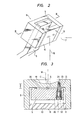
- Fig. 1 is a diagrammatic section view showing one example of a laser beam scanning mechanism according to the invention.
- The laser beam scanning mechanism, as shown in Fig. 1, is incorporated in an
adaptor 2 secured to the lower end of amicroscope body 1. Anadaptor body 3 is in the form of a box having anopening 4 in the lower surface. A supportingplate 5 extends obliquely from the near wall of theadaptor body 3. Asmall fulcrum ball 6 is provided on the supportingplate 5. At least threebolts 7 and at least threesprings 8 are arranged rotationally symmetrically about thefulcrum ball 6, so that amirror holder 9 can be tilted slightly about thefulcrum ball 6. Amirror 10 for reflecting the laser beam is provided in front of themirror holder 9. - A
joystick 12 is provided through aspherical bearing 11 on an upper wall of theadaptor body 3 in such a manner that it is horizontally and vertically movable. - The laser beam reflected by the
mirror surface 13 is applied to a desired part of thetissue 14. That part of thetissue 14 thus irradiated can be-observed through aneye piece 15. The microscopeoptical axis 16 extends from thetissue 14 through theopening 4 to theeye piece 15. - An
incident laser beam 17 is maintained unchanged in direction and position, while thereflected laser beam 18 undergoes angular displacement as the angle of the mirror is changed. - A concave surface 19 (Fig. 3) having a radius of curvature r is formed in the rear surface of the
mirror holder 9. Thejoystick 12 is rockable with one end thereof being in contact with theconcave surface 19. If theeffective length 1 of the stick (which is the distance between the spherical bearing 11 andthe end of the stick 12) is different from the radius of curvature r of the concave surface, then the angle of inclination of themirror holder 9 can be changed by operating the stick. - When the
joystick 12 is moved through an angle a, the mirror is tilted through an angle β. In this case, thereflected laser beam 18 is swung through an angle 2β. - One example of an elastic supporting mechanism for the
mirror holder 9 and the supportingplate 5 are as shown in Figs. 2 and 3. - The
mirror holder 9 and themirror 10 are assembled into one unit which is substantially in the form of a quadrangular prism. Themirror 10 is provided at the front surface of the quadrangular prism, and theconcave surface 19 is formed in the rear surface thereof. The supportingplate 5 is inserted between the front and rear surfaces of the quandrangular prism, i.e., between themirror 10 and theconcave surface 19. - The
bolts 7 are provided rotationally symmetrically about thefulcrum ball 6 of the supportingplate 5. Aspring hole 20 is provided for each bolt. More specifically, the spring hole is bored in the supportingplate 5 at the position of eachbolt 7. Thespring 8 is inserted into thespring hole 20 in such a manner that it is compressed between thebolt head 22 and thestep 21 in thespring hole 20. - The end portion of the
bolt 7 is threadably engaged with a threadedhole 24 in themirror holder 9 through a throughhole 23 in the supporting plate S. - The
mirror holder 9 is pulled towards the supportingplate 5 by means of thesprings 8 and thebolts 7; however, there is agap 25 between themirror holder 9 and the supportingplate 5 because thefulcrum ball 6 is set therebetween. - When the end of the
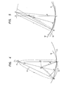
stick 12 is in contact with the center C of the rear surface immediately behind thefulcrum ball 6, the supportingplate 5 is parallel with the surface of themirror holder 9. When, on the other hand, the end of thestick 12 pushes upon a point other than the center C, themirror holder 9 is tilted because the radius of curvature r of the concave surface is different from the effective length A of the joystick. - Fig. 4 outlines the arrangement of the
stick 12 and theconcave surface 19. The relation between the angle of inclination a of the stick and the angle of inclination β of the mirror will be described with reference to Fig. 4. - In Fig. 4, reference numeral A designates the fulcrum of the
stick 12, which corresponds to the center of thespherical bearing 11. - An arc m with a
radius 1 and with the point A as its center is the locus of the end of thestick 12. - Thus, the center C of the arc m is the fulcrum of the
concave surface 19. The center D of theconcave surface 19 is located on the straight line AC, and CD = r (when the stick is disposed at the position AC). - Fig. 4 is for the case where the joystick's
effective length 1 is larger than the radius of curvature r of the concave surface (ℓ > r). - It is assumed that the
stick 12 is moved until its end reaches a point B on the arc m. In this case, the inclination of the concave surface is as indicated at 19'. The concave surface passes through the end point B of the stick and the fulcrum C. Therefore, the center of the concave surface is moved to a point D' which is on the perpendicular bisector of the segment BC and satisfies CD' = r. - The locus of the center of the concave surface is a broken line DD'.
- In this case, the angle of inclination of the concave surface is / D'CD, and
-


- Therefore, both points A and D' are on the perpendicular bisector of the segment BC. Accordingly, the point H is the midpoint, and [ AHC = 90°.
- When the sine rule is applied to the triangle AD'C:

- From equation (5), the angle of inclination β of the mirror is:

- The ratio of the effective length ℓ, of the joystick to the radius of curvature r of the concave surface is set to a ≠ 1, because if a = 1, S = 0.


- The above-described calculation is for Fig. 4, where ℓ > r; however, it should be noted that the same equation can be obtained in the case ℓ < r.
- Fig. 5 is for the case ℓ < r. In Fig. 5, the point A is the stick fulcrum, and AB = AC = ℓ. The points D or D' is the center of the concave surface, and the straight line D'AH is the perpendicular bisector of the segment BC. However, it should be noted that-the sign of β is different from that of a. The angle a should be defined toward the same side as the angle a. In Fig. 5, the angle a is measured towards the left- handed side from the center line AC,' and therefore the angle a has the positive sign. On the other hand, as the angle β is measured towards the right-handed side, the angle β is negative.
- If the definition of the angles a and β include the signs also, the relation between a and β can be represented by equations (6) or (8) irrespective of the difference between the parameters t and r.
- When a/2 is much smaller than one (1), the following expression (9) can approximate the expression (8):

- For instance when a = 0.9,

- That is, with the angle of inclination of the stick reduced by the ratio 20 : 1, the angle of inclination of the mirror can be finely changed. The reduction ratio of the angle variation (R) is as follows:

- Accordingly, as the parameter a is made closer to one (1), the motion of the mirror can be more finely adjusted.
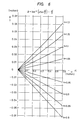
- Fig. 6 is a graphical representation indicating the angles of inclination a of the stick and the angles of inclination β of the mirror with a as the parameter. In Fig. 6, eight values 0.8, 0.85, 0.9, 0.95, 1.05, 1.1, 1.15, and 1.2 are selected for the parameter a.
- The angle of inclination a of the joystick is up to 0.6 radian (34.4°). It can be understood that, in this range, B changes linearly with a.
- The angle of inclination of the mirror has been described above. In this connection, the angle of deflection of the reflected laser beam is 2β, because it is twice the inclination angle of the mirror.
- If the distance between the mirror surface to the tissues is represented by L and the irradiation position on the tissue is represented by x, then the ratio of scanning position displacement with respect to the stick operation can be defined as follows:

- In the case where a/2 is much smaller than one (1), similarly as in the case of expression (9), expression (12) can rewritten as follows:

- If a is made close to one (1), the variation of the irradiation position x can be made considerably small.
- The effects of the invention are as follows:
- (1) As the laser beam scanning mechanism of the invention is considerably simple in construction, the housing of the adapter to the microscope can be miniaturized by as much.
- (2) The laser beam irradiation position can be finely adjusted, because the ratio of the angle of inclination β of the mirror to the angle of inclination a of the joystick is smaller as the ratio of the stick effective length k to the radius of curvature r of the concave surface approaches unity.
- (3) Since no levers or gears are used, no play is involved. In order to obtain fine displacement, it is desirable . that the power transmitting system be free from play. In the invention, there is no play between fulcrum ball, the supporting plate and the mirror holder, and there is no gap between the end of joystick and the concave surface.
- (4) A method in which the motion of the joystick is transmitted to the mirror after being divided into horizontal and vertical components is not employed in the invention. The motion of the stick is equivalent in all directions, and the curvature of the concave surface is the same in all directions.
- Accordingly, the mirror is considerably smoothly movable, and the horizontal reduction ratio is in agreement with the vertical reduction ratio at all times.
- In combining the supporting
plate 5 with themirror holder 9, (1) it is necessary that they be supported by means of thefulcrum ball 6, i.e., one point, and (2) it is essential for themirror holder 9 to be elastically pushed towards the fulcrum ball. Therefore, at least three bolts and at least three springs are provided as described above. In addition, arubber member 26 may be interposed between the supportingplate 5 and the wall of the mirror holder opposite the wall in which the concave surface has been formed. (Fig. 7). Furthermore, in order to provide a fulcrum for the supporting plate and the mirror holder, aprotrusion 27 and arecess 28 for receiving theprotrusion 27 may be provided for the supportingplate 5 and themirror holder 9, respectively, or vice versa. The arrangement of the elastic supporting mechanism is optional. - In the case where the
mirror holder 9 is in the form of a rectangular prism, themirror 10 may be bonded to onesurface 29 thereof. - In the above-described laser beam scanning mechanism, the
concave surface 19 and themirror 10 are provided on the opposite walls of the mirror holder, respectively; however, if the joystick mouting position is changed, then theconcave surface 19 and themirror 10 may_be provided on adjacent walls of the mirror holder. - The fulcrum of the mirror holder must be near the center of the concave surface. With the distance e between the center of the
fulcrum ball 6 and the concave surface center C as shown in Fig. 3, it is unnecessary to add serious correcting terms to equations (6) and (8). - The value a may be larger than one or may be smaller than one. In the case of Fig. 1, the value a must be larger than one (a > 1) so that, when the
stick 12 is moved to the right-handed side, the irradiation point x is moved in the same direction, because the parameters a and Shave the same sign (according to expression (8)). In the case where the microscope forms the erecting image of the object, it is preferable that the value a be larger than one (1), because the positional relationship can be known by intuition. - If a < 1, the direction of the movement of the joystick is opposite to the direction of movement of the irradiation point x. Thus, in the case where the microscope forms an inverted image of the object, it is preferable in operation that the value a be smaller than one (a < 1).
Claims (7)
Applications Claiming Priority (2)
| Application Number | Priority Date | Filing Date | Title |
|---|---|---|---|
| JP108616/81 | 1981-07-10 | ||
| JP56108616A JPS5810040A (en) | 1981-07-10 | 1981-07-10 | Laser beam scanning mechanism |
Publications (3)
| Publication Number | Publication Date |
|---|---|
| EP0069987A2 true EP0069987A2 (en) | 1983-01-19 |
| EP0069987A3 EP0069987A3 (en) | 1984-01-18 |
| EP0069987B1 EP0069987B1 (en) | 1986-10-15 |
Family
ID=14489306
Family Applications (1)
| Application Number | Title | Priority Date | Filing Date |
|---|---|---|---|
| EP82106091A Expired EP0069987B1 (en) | 1981-07-10 | 1982-07-07 | Laser beam scanning mechanism |
Country Status (6)
| Country | Link |
|---|---|
| US (1) | US4545657A (en) |
| EP (1) | EP0069987B1 (en) |
| JP (1) | JPS5810040A (en) |
| AU (1) | AU8577382A (en) |
| CA (1) | CA1190073A (en) |
| DE (1) | DE3273724D1 (en) |
Cited By (2)
| Publication number | Priority date | Publication date | Assignee | Title |
|---|---|---|---|---|
| US4573467A (en) * | 1983-05-13 | 1986-03-04 | The United States Of America As Represented By The Department Of Health And Human Services | Optical coupling device for biomicroscope |
| WO1986006610A1 (en) * | 1985-05-03 | 1986-11-20 | Coopervision, Inc. | Ophthalmic beam director |
Families Citing this family (6)
| Publication number | Priority date | Publication date | Assignee | Title |
|---|---|---|---|---|
| JPH0316662Y2 (en) * | 1987-11-20 | 1991-04-10 | ||
| US5198926A (en) * | 1991-01-18 | 1993-03-30 | Premier Laser Systems, Inc. | Optics for medical laser |
| US6575964B1 (en) | 1998-02-03 | 2003-06-10 | Sciton, Inc. | Selective aperture for laser delivery system for providing incision, tissue ablation and coagulation |
| US6743221B1 (en) | 2001-03-13 | 2004-06-01 | James L. Hobart | Laser system and method for treatment of biological tissues |
| US6770069B1 (en) | 2001-06-22 | 2004-08-03 | Sciton, Inc. | Laser applicator |
| US11400311B2 (en) * | 2016-06-17 | 2022-08-02 | Gensight Biologics | Device for illuminating an object with a controlled light intensity and associated method |
Citations (4)
| Publication number | Priority date | Publication date | Assignee | Title |
|---|---|---|---|---|
| US4091814A (en) * | 1976-03-15 | 1978-05-30 | Mochida Pharmaceutical Co., Ltd. | Laser optical apparatus for operation under a microscope |
| US4141362A (en) * | 1977-05-23 | 1979-02-27 | Richard Wolf Gmbh | Laser endoscope |
| GB2016635A (en) * | 1978-01-04 | 1979-09-26 | Laser Ind Ltd | Mechanical control system particularly useful for directing a laser beam |
| DE3043533A1 (en) * | 1979-11-19 | 1981-06-04 | Asahi Kogaku Kogyo K.K., Tokyo | LIGHT BEAM SWIVELING DEVICE |
Family Cites Families (5)
| Publication number | Priority date | Publication date | Assignee | Title |
|---|---|---|---|---|
| US2876676A (en) * | 1953-12-30 | 1959-03-10 | Libbey Owens Ford Glass Co | Anti-glare rear view mirror with forward view areas |
| DE2226481C3 (en) * | 1972-05-31 | 1981-08-27 | Metallwerk Frese Gmbh, 5653 Leichlingen | Glare-free interior rear-view mirrors |
| US4228341A (en) * | 1978-12-12 | 1980-10-14 | Laser Industries Ltd. | Mechanical control system particularly useful for directing a laser beam |
| US4247161A (en) * | 1979-05-09 | 1981-01-27 | Unertl Jr John | Rifle telescope |
| US4350777A (en) * | 1980-03-28 | 1982-09-21 | Bayer Aktiengesellschaft | Impermeable molded articles of cellular polyurethane elastomers produced with organofunctional polysiloxane-derivatives and their use as spring elements |
-
1981
- 1981-07-10 JP JP56108616A patent/JPS5810040A/en active Granted
-
1982
- 1982-07-06 CA CA000406696A patent/CA1190073A/en not_active Expired
- 1982-07-07 EP EP82106091A patent/EP0069987B1/en not_active Expired
- 1982-07-07 DE DE8282106091T patent/DE3273724D1/en not_active Expired
- 1982-07-08 US US06/396,205 patent/US4545657A/en not_active Expired - Fee Related
- 1982-07-09 AU AU85773/82A patent/AU8577382A/en not_active Abandoned
Patent Citations (4)
| Publication number | Priority date | Publication date | Assignee | Title |
|---|---|---|---|---|
| US4091814A (en) * | 1976-03-15 | 1978-05-30 | Mochida Pharmaceutical Co., Ltd. | Laser optical apparatus for operation under a microscope |
| US4141362A (en) * | 1977-05-23 | 1979-02-27 | Richard Wolf Gmbh | Laser endoscope |
| GB2016635A (en) * | 1978-01-04 | 1979-09-26 | Laser Ind Ltd | Mechanical control system particularly useful for directing a laser beam |
| DE3043533A1 (en) * | 1979-11-19 | 1981-06-04 | Asahi Kogaku Kogyo K.K., Tokyo | LIGHT BEAM SWIVELING DEVICE |
Cited By (3)
| Publication number | Priority date | Publication date | Assignee | Title |
|---|---|---|---|---|
| US4573467A (en) * | 1983-05-13 | 1986-03-04 | The United States Of America As Represented By The Department Of Health And Human Services | Optical coupling device for biomicroscope |
| WO1986006610A1 (en) * | 1985-05-03 | 1986-11-20 | Coopervision, Inc. | Ophthalmic beam director |
| US4686992A (en) * | 1985-05-03 | 1987-08-18 | Coopervision, Inc. | Ophthalmic beam director |
Also Published As
| Publication number | Publication date |
|---|---|
| EP0069987A3 (en) | 1984-01-18 |
| JPS6116167B2 (en) | 1986-04-28 |
| JPS5810040A (en) | 1983-01-20 |
| EP0069987B1 (en) | 1986-10-15 |
| AU8577382A (en) | 1983-01-13 |
| CA1190073A (en) | 1985-07-09 |
| US4545657A (en) | 1985-10-08 |
| DE3273724D1 (en) | 1986-11-20 |
Similar Documents
| Publication | Publication Date | Title |
|---|---|---|
| US4175826A (en) | Adjustable viewing head for a stereoscopic microscope | |
| US4091814A (en) | Laser optical apparatus for operation under a microscope | |
| US5399951A (en) | Robot for guiding movements and control method thereof | |
| EP1769220B1 (en) | Geodesic measuring instrument with a piezo drive | |
| US4988192A (en) | Laser theodolite | |
| EP0069987B1 (en) | Laser beam scanning mechanism | |
| AU5628086A (en) | Ophthalmic beam director | |
| EP1901034A2 (en) | Optical axis tilting device of laser optical system | |
| US4406525A (en) | Light beam scanning device | |
| JPH1038571A (en) | Rotary laser device | |
| JPH10502176A (en) | Microscope support and positioning device | |
| US4228341A (en) | Mechanical control system particularly useful for directing a laser beam | |
| EP0109809A2 (en) | Artificial horizon device | |
| US4607919A (en) | Manipulator for use with a surgical microscope | |
| EP0310514A2 (en) | Binocular microscope | |
| JPS5933885B2 (en) | Joint for observation device | |
| JPH0322360B2 (en) | ||
| JPH0134152Y2 (en) | ||
| JP3558424B2 (en) | Light wave aridart | |
| JP2559741Y2 (en) | Surgical microscope | |
| SU883838A1 (en) | Device for concave mirror adjustment | |
| JP2001046400A (en) | Microscope for operation | |
| JP2001041746A (en) | Measurement device | |
| JPH0637285Y2 (en) | Rotating axis fine movement device of surveying instrument | |
| JPH0219854Y2 (en) |
Legal Events
| Date | Code | Title | Description |
|---|---|---|---|
| PUAI | Public reference made under article 153(3) epc to a published international application that has entered the european phase |
Free format text: ORIGINAL CODE: 0009012 |
|
| AK | Designated contracting states |
Designated state(s): DE FR GB SE |
|
| PUAL | Search report despatched |
Free format text: ORIGINAL CODE: 0009013 |
|
| AK | Designated contracting states |
Designated state(s): DE FR GB SE |
|
| 17P | Request for examination filed |
Effective date: 19840229 |
|
| GRAA | (expected) grant |
Free format text: ORIGINAL CODE: 0009210 |
|
| AK | Designated contracting states |
Kind code of ref document: B1 Designated state(s): DE FR GB SE |
|
| ET | Fr: translation filed | ||
| REF | Corresponds to: |
Ref document number: 3273724 Country of ref document: DE Date of ref document: 19861120 |
|
| PLBE | No opposition filed within time limit |
Free format text: ORIGINAL CODE: 0009261 |
|
| STAA | Information on the status of an ep patent application or granted ep patent |
Free format text: STATUS: NO OPPOSITION FILED WITHIN TIME LIMIT |
|
| 26N | No opposition filed | ||
| EAL | Se: european patent in force in sweden |
Ref document number: 82106091.0 |
|
| PGFP | Annual fee paid to national office [announced via postgrant information from national office to epo] |
Ref country code: GB Payment date: 19950626 Year of fee payment: 14 |
|
| PGFP | Annual fee paid to national office [announced via postgrant information from national office to epo] |
Ref country code: DE Payment date: 19950710 Year of fee payment: 14 |
|
| PGFP | Annual fee paid to national office [announced via postgrant information from national office to epo] |
Ref country code: FR Payment date: 19950711 Year of fee payment: 14 |
|
| PGFP | Annual fee paid to national office [announced via postgrant information from national office to epo] |
Ref country code: SE Payment date: 19950717 Year of fee payment: 14 |
|
| PG25 | Lapsed in a contracting state [announced via postgrant information from national office to epo] |
Ref country code: GB Effective date: 19960707 |
|
| PG25 | Lapsed in a contracting state [announced via postgrant information from national office to epo] |
Ref country code: SE Effective date: 19960708 |
|
| GBPC | Gb: european patent ceased through non-payment of renewal fee |
Effective date: 19960707 |
|
| PG25 | Lapsed in a contracting state [announced via postgrant information from national office to epo] |
Ref country code: FR Effective date: 19970328 |
|
| PG25 | Lapsed in a contracting state [announced via postgrant information from national office to epo] |
Ref country code: DE Effective date: 19970402 |
|
| EUG | Se: european patent has lapsed |
Ref document number: 82106091.0 |
|
| REG | Reference to a national code |
Ref country code: FR Ref legal event code: ST |