EP0070623A2 - Reaction cuvette - Google Patents
Reaction cuvette Download PDFInfo
- Publication number
- EP0070623A2 EP0070623A2 EP82303211A EP82303211A EP0070623A2 EP 0070623 A2 EP0070623 A2 EP 0070623A2 EP 82303211 A EP82303211 A EP 82303211A EP 82303211 A EP82303211 A EP 82303211A EP 0070623 A2 EP0070623 A2 EP 0070623A2
- Authority
- EP
- European Patent Office
- Prior art keywords
- tray
- liquid
- cuvette
- cuvettes
- reaction
- Prior art date
- Legal status (The legal status is an assumption and is not a legal conclusion. Google has not performed a legal analysis and makes no representation as to the accuracy of the status listed.)
- Granted
Links
Images


Classifications
-
- G—PHYSICS
- G01—MEASURING; TESTING
- G01N—INVESTIGATING OR ANALYSING MATERIALS BY DETERMINING THEIR CHEMICAL OR PHYSICAL PROPERTIES
- G01N21/00—Investigating or analysing materials by the use of optical means, i.e. using sub-millimetre waves, infrared, visible or ultraviolet light
- G01N21/01—Arrangements or apparatus for facilitating the optical investigation
- G01N21/03—Cuvette constructions
-
- G—PHYSICS
- G01—MEASURING; TESTING
- G01N—INVESTIGATING OR ANALYSING MATERIALS BY DETERMINING THEIR CHEMICAL OR PHYSICAL PROPERTIES
- G01N21/00—Investigating or analysing materials by the use of optical means, i.e. using sub-millimetre waves, infrared, visible or ultraviolet light
- G01N21/17—Systems in which incident light is modified in accordance with the properties of the material investigated
- G01N21/25—Colour; Spectral properties, i.e. comparison of effect of material on the light at two or more different wavelengths or wavelength bands
- G01N21/251—Colorimeters; Construction thereof
- G01N21/253—Colorimeters; Construction thereof for batch operation, i.e. multisample apparatus
-
- G—PHYSICS
- G01—MEASURING; TESTING
- G01N—INVESTIGATING OR ANALYSING MATERIALS BY DETERMINING THEIR CHEMICAL OR PHYSICAL PROPERTIES
- G01N35/00—Automatic analysis not limited to methods or materials provided for in any single one of groups G01N1/00 - G01N33/00; Handling materials therefor
- G01N35/02—Automatic analysis not limited to methods or materials provided for in any single one of groups G01N1/00 - G01N33/00; Handling materials therefor using a plurality of sample containers moved by a conveyor system past one or more treatment or analysis stations
Definitions
- This invention relates to a container useful as a reaction cuvette, and to a reaction tray comprised of a plurality of such reaction cuvettes, for use in automated analysis systems.
- the probe is immersed in a wash liquid reservoir to remove contaminants from or "wash" both interior and exterior probe surfaces.
- contamination between successive sample segments in the continuous stream is very substantially reduced by introducing an immiscible liquid, e.g. silicone, fluorocarbon oil, etc. between successive sample segments.
- the immiscible liquid preferentially wets the interior surfaces of the analytical system, to the complete exclusion of the aqueous sample segments.
- the sample segments are, in effect, completely encapsulated by the immiscible liquid, whereby contamination between successive sample segments is completely avoided.
- controlled volumes of the aqueous sample and appropriate reagents are precisely metered into a reaction cuvette, the depth of color of the reaction mixture being measured to determine the analyte concentration.
- metering is effected by precisely aspirating a predetermined volume of sample or reagent and dispensing them into the reaction cuvette.
- Contaminants and other residues from a previous metering operation are removed from the external probe surface by immersing the probe in a wash-liquid reservoir. Often, the probe is reverse-flushed with an appropriate liquid to clean the interior probe surfaces.
- the metering system described in U.S. patent 4,121,466 provides very beneficial results in positively eliminating contamination between successively dispensed liquid segments and, also, between sources of different liquids in which the probe is selectively immersed.
- the liquid segment, whether sample or reagent, dispensed into the reaction cuvette may be encapsulated within a film of the immiscible liquid.
- a surfactant is present in the liquid being netered, there is a strong tendency for the sample or a portion thereof to remain encapsulated within the immiscible liquid film, which is not easily ruptured during the dispensing cycle. Unless such encapsulating film is ruptured, the dispensed liquid segment is not available for reaction.
- a cup-like receptacle the interior of said receptacle defining at least one surface which has a plurality of inwardly extending projections of hydrophilic material, said receptacle further defining a sight passageway for analysis of said liquid.
- the invention also includes a reaction tray comprising a plurality of reaction cuvettes, said tray adapted to be rotated about an axis, said cuvettes being circularly disposed about said axis, whereby rotation of said tray advances each cuvette, in turn, to a liquid dispensing station, the interior of each cuvette defining at least one surface which has a plurality of inwardly extending projections of hydrophilic material and each of said cuvettes defining a sight passageway for analysis of the contents thereof.
- At least one surface is formed of a hydrophilic material and structured to engage with and penetrate any encapsulating immiscible film, so as to rupture it.
- the cuvette bottom defines one or more projections against which the encapsulated liquid segment is positively directed, so as to forcibly penetrate and rupture such encapsulating film. Once penetrated, the surface forces of such encapsulating film are insufficient to maintain the aqueous liquid encapsulated, and the aqueous liquid is thus released and available for reaction.
- the outlet end of the probe will be located immediately adjacent the projections on the bottom surface of the reaction cuvette. Accordingly, the encapsulating immiscible film, which tends to form a sphere, is dispensed against the bottom surface of the cuvette and deformed against the projections to the point of rupturing. Once ruptured, the immiscible liquid does not interfere with the reaction because it is inert towards the various reactants.
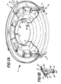
- the reaction tray 1 of the present invention comprises a plurality of cup-like containers or cuvettes 3, formed in integral fashion and arranged circularly along the periphery of tray 1.
- Tray 1 is preferably molded of clear acrylic polystyrene or other suitable transparent inert material. Reinforcing ribs 4 provide rigidity to tray 1.
- Tray 1 is adapted to be mounted through a central opening 5 and keyed by slot 7 to an intermittently rotated shaft, not shown, to rotate about its axis.
- a collar 9 is provided which defines slot 7 and facilitates positioning and removal of tray 1 from such shaft.
- Rotation of such shaft is operative to position each cuvette 3 successively at a reagent dispensing station 11, a sample dispensing station 13, and at an optical read-out station 15.
- a reagent dispensing station 11 a sample dispensing station 13
- an optical read-out station 15 As the use of reaction trays in discrete-type analytical systems is well understood and in the interest of expediency, such stations have not been illustrated in detail. Rather, dispending probes 17 and 19 are shown as symbolic of the reagent and sample dispense stations, respectively. Probes 17 and 19 are each adapted, as indicated by the adjacent arrow S, to be displaced vertically, so as to be introduced into and withdrawn from the cuvettes positioned at the reagent and sample dispensing stations 11 and 13, respectively.
- probes 17 and 19 when elevated, are adapted to be moved in a horizontal plane, so as to be positioned at aspiration stations located over sources of reagent and sample, respectively.
- the probe 17 When so positioned, the probe 17 would be immersed into such reagent source selectively to aspirate a predetermined volume of reagent which is dispensed into a cuvette 3 located at the dispensing station 11.
- the probe 19 when such cuvette 3 has been advanced to the sample dispense station, the probe 19 would be immersed into such sample source to aspirate a predetermined volume of sample which is dispensed and reacted in such cuvette.
- probes 17 and 19 are more particularly described hereafter and may take the general form of the aspirator-dispenser unit described in U.S. Patent 4,121,466. Subsequently, the cuvette 3 is advanced to optical read-out station 15, whereat the analyte is colorimetrically analyzed, by conventional techniques.
- each cuvette 3 has a substantially rectangular configuration and extends downwardly from the plane of reaction tray 1.
- Each cuvette 3 includes opposing parallel walls 21 and 21' and 23 and 23', the latter defining tapered portions 25 and 25', respectively. Wall portions 25 and 25' are integral with tab portions 27 and 27', respectively.
- tab portions 27 and 27' are integrally defined in tray 1. However, tab portions 27 and 27' would allow support, if cuvette 3 is to be mounted in slots defined in a non-disposable type of turntable.
- the bottom 29 of each cuvette defines a plurality of upward projections or ribs 31, whose particular function is hereinafter described. Opposing walls 23 and 23' of each cuvette 3 are at a precisely controlled separation.
- Walls 23 and 23' define a sight path to colorimetrically analyze the reacted sample.
- a light beam from source 33 is directed through lens arrangement 35 and along such sight path.
- the emerging light is incident on detector 37, which produces an output indicative of the concentration of the analyte being measured and which is recorded by recorder 39.
- FIGs 2A and 2B illustrate the aspiration cycles of both probes 17 and 19 of Figure 1.
- a container 41 is representative of the reagent source and of sample source into which probes 17 and 19, respectively, of Figure 1A would be immersed.
- probe 43 is representative of probes 17 and 19. It will be appreciated that the respective operations of probes 17 and 19 are identical, except in respect of the particular aqueous liquid to be aspirated, i.e. sample or reagent.
- probe 43 is immersed into container 41 and a controlled negative pressure is applied at the outlet end, as by a pump, to aspirate a controlled volume of the aqueous liquid 45.
- a controlled negative pressure is applied at the outlet end, as by a pump, to aspirate a controlled volume of the aqueous liquid 45.
- an immiscible fluid 47 is flowed downwardly, at a controlled rate, over outer surface of probe 43 from a chamber, not illustrated, to coat such surface and prevent contact with the liquid to be aspirated. During immersion of probe 43, to effect either an aspirate or dispense operation, the flow of immiscible liquid may be discontinued.
- the probe is normally filled with immiscible fluid 47, which serves as pilot fluid to dispense the aspirated liquid segment.
- immiscible fluid 47 serves as pilot fluid to dispense the aspirated liquid segment.
- probe 43 is immersed into liquid 45 contained in the vessel.
- the flow of externally wetting immiscible fluid 47 is discontinued and liquid 45 is aspirated into the probe, as shown in Figure 2A.
- the immiscible liquid 47 preferentially wets the interior and exterior probe surfaces, to the exclusion of the liquid 45, the aspirated liquid tends to form a discrete segment, which is encased within immiscible liquid and, hence, prevented from contacting the probe surfaces.
- reagent sources may be provided into which probe 17 of Figure 1A is selectively immersed, such that sample segments introduced, in turn, into cuvettes 3 at sample dispense station 13 may be reached and analyzed for different analytes, on a selective basis.
- FIGS 3A-3C illustrate a sample dispense station exemplary of the prior art, whereat the cuvette 49 contains a previously dispensed liquid 51, i.e. reagent.
- cuvette 3 has a planar, substantially smooth bottom 53.
- probe 43 is immersed into cuvette 49, the flow of immiscible liquid 47 over the outer probe surfaces is discontinued and a portion thereof is left behind, to form a film over the surface of liquid 51, as described.
- the end of probe 43 is sealed with immiscible fluid 47 and liquid segment 45' remains encapsulated.
- Figure 3C illustrates the situation where the end of probe 43 is located adjacent to the bottom 53 of cuvette 49. As shown, the emerging liquid segment 45' encapsulated in barrier film 47' is pressed against bottom 53. Because of the smoothness of bottom 43, the encapsulated liquid sample 45' becomes distorted and slips from between the end of probe 43 and bottom 53, as shown, with barrier film 47' intact, such as to form a globule 55, as shown in Figure 3B.
- the novel structure of cuvette 3 of the present invention ensures that the barrier film is prevented from forming a complete encapsulation of the dispensed liquid segment.
- the bottom 29 of cuvette 3 is provided with one or more upward projections or ridges 31.
- the inlet end is located adjacent to bottom 29.
- the spacing between bottom 29, i.e. ridges 31, and the inlet of probe 33, should be sufficient to prevent build up of significant back pressure along the probe system during the dispensing cycle, such as not to affect metering, and also be less than the diameter of any globule which might tend to form.
- the liquid segment 45' encapsulated in barrier layer 47' is compressed against ridges 31.
- the barrier film 47' is forced against the ridges 31, which penetrate and prevent slippage of the barrier layer 47'.
- the ridges 31 will ultimately pierce barrier layer 47'.
- bottom 29 is formed of hydrophilic material, ridges 31 provide a hydrophilic path or "bridge” accelerating the release of liquid segment 45' to mix with reagent 45 in cuvette 3, as shown in Figure 4B.
- Barrier layer 47' would be similarly ruptured, notwithstanding cuvette 3 contains no priorly dispensed liquid, as in the case of the dispensing of reagent at reagent dispensing station 11. Accordingly, the cuvette structure of the invention ensures the availability of the dispensed liquid segment 45', while full advantage is made of the immiscible fluid to prevent contamination, whether between reagent sources into which the probe is selectively immersed or successive sample sources.
- the upper surface of bottom 29 should be treated or formed to accelerate rupturing of barrier film 47' by preventing slippage of the emerging globule from between the inlet end of probe 43 and such surface.
- the bottom surface for example, may be sand-blasted, as shown in Figure 5A, to ensure non-slippage of the emerging globule, the microscopic projections thus defined in the surface serving to penetrate and restrain the barrier film 47'.
- bottom 29 may be provided with cone-like projections 57, as shown in Figure 5B, or rod-like projections 59, as shown in Figure 5C, or any specialized hydrophilic surface designed so as to restrain the emerging globule and provide piercing projections.
- the invention further includes:
Abstract
Description
- This invention relates to a container useful as a reaction cuvette, and to a reaction tray comprised of a plurality of such reaction cuvettes, for use in automated analysis systems.
- In the field of automated analysis, wherein aqueous samples are reacted in turn in respect of one or more analytes, contamination between successive samples is a major problem. In continuous-flow analytical systems as described in Skeggs et al U.S. Patent 3,241,432, and in the Smythe et al U.S. Patent 3,479,141, sample segments are successively introduced into the system by means of a single aspirating probe. In the Skeggs et al patent, a sequence of air-wash liquid-air segments is aspirated between successive sample segments to substantially reduce contamination therebetween. The sample segments, thus separated, are passed as a continuous stream through the analytical system, so as to be reacted and analyzed in "on-line" fashion. During aspiration of each wash liquid segment, the probe is immersed in a wash liquid reservoir to remove contaminants from or "wash" both interior and exterior probe surfaces. In the Smythe et al patent, contamination between successive sample segments in the continuous stream is very substantially reduced by introducing an immiscible liquid, e.g. silicone, fluorocarbon oil, etc. between successive sample segments. The immiscible liquid preferentially wets the interior surfaces of the analytical system, to the complete exclusion of the aqueous sample segments. The sample segments are, in effect, completely encapsulated by the immiscible liquid, whereby contamination between successive sample segments is completely avoided.
- Also, in analytical systems which do not utilize continuous-flow techniques, hereafter designated discrete systems, controlled volumes of the aqueous sample and appropriate reagents are precisely metered into a reaction cuvette, the depth of color of the reaction mixture being measured to determine the analyte concentration. Generally, such metering is effected by precisely aspirating a predetermined volume of sample or reagent and dispensing them into the reaction cuvette. Contaminants and other residues from a previous metering operation are removed from the external probe surface by immersing the probe in a wash-liquid reservoir. Often, the probe is reverse-flushed with an appropriate liquid to clean the interior probe surfaces.
- In the Reichler et al U.S. Patent 4,121,466, an improved metering or dispensing system, useful in both continuous-flow and discrete systems, is described, wherein contamination between successively aspirated liquids is completely avoided. In this system, the external and internal probe surfaces which normally contact the aqueous liquids, whether sample or reagent, are continuously coated with a thin film of liquid, which is immiscible with the aqueous test liquids and preferentially wets the probe surfaces. Also, the aqueous liquid segments aspirated into the probe for dispensing are completely encapsulated within the immiscible liquid. Hence, the interior and exterior probe surfaces are not in contact with the aqueous liquid during either the aspiration or dispense cycles.
- Admittedly, the metering system described in U.S. patent 4,121,466 provides very beneficial results in positively eliminating contamination between successively dispensed liquid segments and, also, between sources of different liquids in which the probe is selectively immersed. However, when used as a dispenser in a discrete system, the liquid segment, whether sample or reagent, dispensed into the reaction cuvette may be encapsulated within a film of the immiscible liquid. In certain instances, for example where a surfactant is present in the liquid being netered, there is a strong tendency for the sample or a portion thereof to remain encapsulated within the immiscible liquid film, which is not easily ruptured during the dispensing cycle. Unless such encapsulating film is ruptured, the dispensed liquid segment is not available for reaction.
- We have now devised a reaction cuvette whereby this problem can be substantially reduced or eliminated by positively ensuring that any encapsulating film is ruptured during the disensing cycle.
- According to the invention, there is provided a cup-like receptacle, the interior of said receptacle defining at least one surface which has a plurality of inwardly extending projections of hydrophilic material, said receptacle further defining a sight passageway for analysis of said liquid.
- The invention also includes a reaction tray comprising a plurality of reaction cuvettes, said tray adapted to be rotated about an axis, said cuvettes being circularly disposed about said axis, whereby rotation of said tray advances each cuvette, in turn, to a liquid dispensing station, the interior of each cuvette defining at least one surface which has a plurality of inwardly extending projections of hydrophilic material and each of said cuvettes defining a sight passageway for analysis of the contents thereof.
- In the cuvettes of the invention, at least one surface, preferably the bottom surface, is formed of a hydrophilic material and structured to engage with and penetrate any encapsulating immiscible film, so as to rupture it. In a preferred embodiment, the cuvette bottom defines one or more projections against which the encapsulated liquid segment is positively directed, so as to forcibly penetrate and rupture such encapsulating film. Once penetrated, the surface forces of such encapsulating film are insufficient to maintain the aqueous liquid encapsulated, and the aqueous liquid is thus released and available for reaction.
- During the dispensing cycle, the outlet end of the probe will be located immediately adjacent the projections on the bottom surface of the reaction cuvette. Accordingly, the encapsulating immiscible film, which tends to form a sphere, is dispensed against the bottom surface of the cuvette and deformed against the projections to the point of rupturing. Once ruptured, the immiscible liquid does not interfere with the reaction because it is inert towards the various reactants.
- In order that the invention may be more fully understood, reference is made to the accompanying drawings, wherein:
- Figure 1A is an isometric view of one embodiment of reaction tray of the invention, the tray being comprised of a plurality of reaction cuvettes of the invention;
- Figure 1B is an isometric view of one embodiment of reaction cuvette;
- Figures 2A and 2B are illustrative of the aspirating cycle and Figures 3A, 3B and 3C are illustrative of the dispensing cycle of an aspirating/ dispensing probe, such as described in U.S.
Patent 4,121,466; - Figures 4A and 4B provide a cross-section view of an embodiment of reaction cuvette of the present invention; and
- Figures 5A, 5B and 5C are fragmentary views of other embodiments of reaction cuvette of the present invention.
- Referring to Figure 1, the reaction tray 1 of the present invention comprises a plurality of cup-like containers or
cuvettes 3, formed in integral fashion and arranged circularly along the periphery oftray 1.Tray 1 is preferably molded of clear acrylic polystyrene or other suitable transparent inert material. Reinforcingribs 4 provide rigidity to tray 1.Tray 1 is adapted to be mounted through a central opening 5 and keyed by slot 7 to an intermittently rotated shaft, not shown, to rotate about its axis. A collar 9 is provided which defines slot 7 and facilitates positioning and removal oftray 1 from such shaft. Rotation of such shaft is operative to position eachcuvette 3 successively at a reagent dispensing station 11, asample dispensing station 13, and at an optical read-out station 15. As the use of reaction trays in discrete-type analytical systems is well understood and in the interest of expediency, such stations have not been illustrated in detail. Rather, dispendingprobes Probes sample dispensing stations 11 and 13, respectively. It will be appreciated thatprobes probe 17 would be immersed into such reagent source selectively to aspirate a predetermined volume of reagent which is dispensed into acuvette 3 located at the dispensing station 11. Also, whensuch cuvette 3 has been advanced to the sample dispense station, theprobe 19 would be immersed into such sample source to aspirate a predetermined volume of sample which is dispensed and reacted in such cuvette. The aspirating and dispensing cycles ofprobes cuvette 3 is advanced to optical read-out station 15, whereat the analyte is colorimetrically analyzed, by conventional techniques. - As illustrated in Figures 1A and 1B, each
cuvette 3 has a substantially rectangular configuration and extends downwardly from the plane ofreaction tray 1. Eachcuvette 3 includes opposingparallel walls 21 and 21' and 23 and 23', the latter definingtapered portions 25 and 25', respectively.Wall portions 25 and 25' are integral withtab portions 27 and 27', respectively. In Figure 1A,tab portions 27 and 27' are integrally defined intray 1. However,tab portions 27 and 27' would allow support, ifcuvette 3 is to be mounted in slots defined in a non-disposable type of turntable. Thebottom 29 of each cuvette defines a plurality of upward projections orribs 31, whose particular function is hereinafter described. Opposing walls 23 and 23' of eachcuvette 3 are at a precisely controlled separation. Walls 23 and 23' define a sight path to colorimetrically analyze the reacted sample. When acuvette 3 is positioned, in turn, at read-out station 15, a light beam fromsource 33 is directed through lens arrangement 35 and along such sight path. The emerging light is incident ondetector 37, which produces an output indicative of the concentration of the analyte being measured and which is recorded byrecorder 39. - To appreciate the advantages of the present invention, reference is initially made to Figures 2A and 2B, which illustrate the aspiration cycles of both
probes container 41 is representative of the reagent source and of sample source into whichprobes probe 43 is representative ofprobes probes probe 43 is immersed intocontainer 41 and a controlled negative pressure is applied at the outlet end, as by a pump, to aspirate a controlled volume of theaqueous liquid 45. As particularly described in U.S. Patent 4,212,466, animmiscible fluid 47 is flowed downwardly, at a controlled rate, over outer surface ofprobe 43 from a chamber, not illustrated, to coat such surface and prevent contact with the liquid to be aspirated. During immersion ofprobe 43, to effect either an aspirate or dispense operation, the flow of immiscible liquid may be discontinued. - At the beginning of each aspiration cycle, the probe is normally filled with
immiscible fluid 47, which serves as pilot fluid to dispense the aspirated liquid segment. To initiate an aspiration cycle,probe 43 is immersed intoliquid 45 contained in the vessel. At such time, the flow of externally wettingimmiscible fluid 47 is discontinued and liquid 45 is aspirated into the probe, as shown in Figure 2A. As theimmiscible liquid 47 preferentially wets the interior and exterior probe surfaces, to the exclusion of the liquid 45, the aspirated liquid tends to form a discrete segment, which is encased within immiscible liquid and, hence, prevented from contacting the probe surfaces. - During probe immersion, a small portion of excess
immiscible fluid 47 is wiped from the outer surface ofprobe 43, due to the surface tension ofliquid 45 and forms a film over the surface ofliquid 45 incontainer 41. Asprobe 43 is withdrawn, such excess immiscible liquid tends to seal the inlet end ofprobe 43 and fully encapsulate the aspiratedliquid segment 45', as shown in Figure 2B. Such encapsulation serves, as is known, to prevent contact betweenliquid segment 45' and the inner surfaces ofprobe 43, to prevent contamination between successively aspirated liquid segments. Also, the film ofimmiscible liquid 47 coating the outer surfaces ofprobe 43 to prevent contamination between successive liquid sources into whichprobe 43 may be selectively immersed. It will be appreciated that a number of reagent sources may be provided into whichprobe 17 of Figure 1A is selectively immersed, such that sample segments introduced, in turn, intocuvettes 3 at sample dispensestation 13 may be reached and analyzed for different analytes, on a selective basis. - To initiate the dispense cycle,
probe 43 is moved to the dispense station, whether reagent or sample, and positioned over thecuvette 3 located thereat. For purposes of description, Figures 3A-3C illustrate a sample dispense station exemplary of the prior art, whereat thecuvette 49 contains a previously dispensedliquid 51, i.e. reagent. As illustrated,cuvette 3 has a planar, substantially smooth bottom 53. Again probe 43 is immersed intocuvette 49, the flow of immiscible liquid 47 over the outer probe surfaces is discontinued and a portion thereof is left behind, to form a film over the surface ofliquid 51, as described. At this time, the end ofprobe 43 is sealed withimmiscible fluid 47 andliquid segment 45' remains encapsulated. Asliquid segment 45' is dispensed, a portion ofimmiscible fluid 47 sealing the inlet end ofprobe 43 forms a thin barrier film 47' which is expanded by the emerging segment, as shown in Figure 3A. Asliquid segment 45' continues to emerge, the barrier film 47' continues to expand and surrounds theliquid segment 45', the surface tensions within both tending toward a spherical or globular shape. Whenliquid segment 45' has emerged sufficiently fromprobe 43, as aglobule 55, as shown in Figure 3B. It will be appreciated that, ifliquid segment 45' is of considerable size, a series of such globules will be dispensed intocuvette 49. In many instances, the barrier film 47' remains intact, whether dispensed into a liquid medium or into an empty cuvette, whereby the encapsulatedliquid segment 45' is unavailable for reaction. - Figure 3C illustrates the situation where the end of
probe 43 is located adjacent to the bottom 53 ofcuvette 49. As shown, the emergingliquid segment 45' encapsulated in barrier film 47' is pressed against bottom 53. Because of the smoothness of bottom 43, the encapsulatedliquid sample 45' becomes distorted and slips from between the end ofprobe 43 and bottom 53, as shown, with barrier film 47' intact, such as to form aglobule 55, as shown in Figure 3B. - The novel structure of
cuvette 3 of the present invention ensures that the barrier film is prevented from forming a complete encapsulation of the dispensed liquid segment. As shown in Figure 4A, the bottom 29 ofcuvette 3 is provided with one or more upward projections orridges 31. During the dispensing cycle, the inlet end is located adjacent to bottom 29. The spacing betweenbottom 29, i.e.ridges 31, and the inlet ofprobe 33, should be sufficient to prevent build up of significant back pressure along the probe system during the dispensing cycle, such as not to affect metering, and also be less than the diameter of any globule which might tend to form. During the dispensing operation, theliquid segment 45' encapsulated in barrier layer 47' is compressed againstridges 31. As theliquid segment 45' continues to emerge, the barrier film 47' is forced against theridges 31, which penetrate and prevent slippage of the barrier layer 47'. Asliquid segment 45' continues to emerge fromprobe 43, such layer is ruptured to releaseliquid segment 45'. Alternatively, theridges 31 will ultimately pierce barrier layer 47'. As bottom 29 is formed of hydrophilic material,ridges 31 provide a hydrophilic path or "bridge" accelerating the release ofliquid segment 45' to mix withreagent 45 incuvette 3, as shown in Figure 4B. Barrier layer 47' would be similarly ruptured, notwithstandingcuvette 3 contains no priorly dispensed liquid, as in the case of the dispensing of reagent at reagent dispensing station 11. Accordingly, the cuvette structure of the invention ensures the availability of the dispensedliquid segment 45', while full advantage is made of the immiscible fluid to prevent contamination, whether between reagent sources into which the probe is selectively immersed or successive sample sources. - While
ridges 31 have been shown, it will be appreciated that numerous alternate structures can be utilized to achieve similar results. To obtain advantages of the present invention, the upper surface of bottom 29 should be treated or formed to accelerate rupturing of barrier film 47' by preventing slippage of the emerging globule from between the inlet end ofprobe 43 and such surface. The bottom surface, for example, may be sand-blasted, as shown in Figure 5A, to ensure non-slippage of the emerging globule, the microscopic projections thus defined in the surface serving to penetrate and restrain the barrier film 47'. Also, bottom 29 may be provided with cone-like projections 57, as shown in Figure 5B, or rod-like projections 59, as shown in Figure 5C, or any specialized hydrophilic surface designed so as to restrain the emerging globule and provide piercing projections. - Among the preferred features of the invention are the following:
- a) a receptacle which is adapted to be mounted onto a horizontal support, further including means projecting laterally of said receptacle for supporting said receptacle when mounted on said horizontal support.
- b) a receptacle which includes two opposing non-parallel wall portions for directing said receptacle when mounting on said support.
- c) a receptacle which is formed of acrylic or polystyrene material.
- d) a receptacle in which at least the portions of said opposing walls which define said sight passageway have hydrophilic interior surface.
- e) a reaction tray which includes a structure surrounding said central opening for facilitating mounting of said reaction tray on said shaft.
- The invention further includes:
- i) A cup-like receptacle adapted to receive a liquid, which receptacle has a sight passageway for analysis of the contents thereof, and means for rupturing an encapsulated globule of said liquid received therein.
- ii) A reaction tray comprising a plurality of reaction cuvettes, said tray adapted to be moved relative to a liquid dispensing station to successively advance each cuvette to said liquid dispensing station, wherein each cuvette has a sight passageway for analysis of the contents thereof, and means for rupturing an immiscible liquid encapsulated globule of said liquid.
- iii) A method of analysis of an queous liquid in which a reaction mixture is formed in a reaction cuvette by dispensing liquid from a liquid dispensing probe coated with an immiscible fluid inserted in the cuvette, characterised in that the cuvette is as defined and the tip of the probe is located adjacent said at least one surface of the cuvette whereby encapsulation of dispensed liquid in a film of the immiscible fluid is avoided by rupture of said film on said projection.
Claims (10)
Priority Applications (1)
| Application Number | Priority Date | Filing Date | Title |
|---|---|---|---|
| AT82303211T ATE24357T1 (en) | 1981-07-20 | 1982-06-21 | REACTION CUVETTE. |
Applications Claiming Priority (2)
| Application Number | Priority Date | Filing Date | Title |
|---|---|---|---|
| US06/284,845 US4357301A (en) | 1981-07-20 | 1981-07-20 | Reaction cuvette |
| US284845 | 1981-07-20 |
Publications (3)
| Publication Number | Publication Date |
|---|---|
| EP0070623A2 true EP0070623A2 (en) | 1983-01-26 |
| EP0070623A3 EP0070623A3 (en) | 1984-07-04 |
| EP0070623B1 EP0070623B1 (en) | 1986-12-17 |
Family
ID=23091750
Family Applications (1)
| Application Number | Title | Priority Date | Filing Date |
|---|---|---|---|
| EP82303211A Expired EP0070623B1 (en) | 1981-07-20 | 1982-06-21 | Reaction cuvette |
Country Status (21)
| Country | Link |
|---|---|
| US (1) | US4357301A (en) |
| EP (1) | EP0070623B1 (en) |
| JP (1) | JPS5844349A (en) |
| KR (1) | KR880001335B1 (en) |
| AR (1) | AR228980A1 (en) |
| AT (1) | ATE24357T1 (en) |
| AU (1) | AU550802B2 (en) |
| BR (1) | BR8203762A (en) |
| CA (1) | CA1169342A (en) |
| DE (1) | DE3274762D1 (en) |
| DK (1) | DK157263C (en) |
| ES (1) | ES513688A0 (en) |
| FI (1) | FI74814C (en) |
| GB (1) | GB2104653B (en) |
| HK (1) | HK21186A (en) |
| IN (1) | IN158347B (en) |
| MX (1) | MX170970B (en) |
| MY (1) | MY8600507A (en) |
| NO (1) | NO161238C (en) |
| NZ (1) | NZ200898A (en) |
| ZA (1) | ZA824512B (en) |
Cited By (3)
| Publication number | Priority date | Publication date | Assignee | Title |
|---|---|---|---|---|
| EP0172540A2 (en) * | 1984-08-21 | 1986-02-26 | E.I. Du Pont De Nemours And Company | Analysis instrument having a blow molded reaction chamber |
| US4863693A (en) * | 1984-08-21 | 1989-09-05 | E. I. Du Pont De Nemours And Company | Analysis instrument having a blow molded reaction chamber |
| DE112010001385B4 (en) * | 2009-03-27 | 2013-11-21 | Hitachi High-Technologies Corporation | Automatic analyzer and pipetting tip for an automated analyzer |
Families Citing this family (32)
| Publication number | Priority date | Publication date | Assignee | Title |
|---|---|---|---|---|
| US4515753A (en) * | 1982-11-15 | 1985-05-07 | Technicon Instruments Corporation | Integral reagent dispenser |
| CA1209820A (en) * | 1982-12-29 | 1986-08-19 | Claude Borer | Photometrical measurement and cuvette for performing it |
| JPS6094912A (en) * | 1983-10-28 | 1985-05-28 | Masashige Suzuki | Agent for reducing neutral fat in body |
| US4580896A (en) * | 1983-11-07 | 1986-04-08 | Allied Corporation | Multicuvette centrifugal analyzer rotor with annular recessed optical window channel |
| FI68916C (en) * | 1983-12-30 | 1985-11-11 | Kone Oy | FOERFARANDE FOER ATT LADDA ETT INSTRUMENT MED KYVETTER SAMT ENYVETTFOERPACKNING |
| US4865993A (en) * | 1985-04-11 | 1989-09-12 | Technicon Instruments Corporation | Minimum carryover container, and analysis system incorporating the same |
| US4720374A (en) * | 1985-07-22 | 1988-01-19 | E. I. Du Pont De Nemours And Company | Container having a sonication compartment |
| US4678641A (en) * | 1986-06-30 | 1987-07-07 | Technicon Instruments Corporation | Isolation liquid layer retention device |
| US4855110A (en) * | 1987-05-06 | 1989-08-08 | Abbott Laboratories | Sample ring for clinical analyzer network |
| US4971912A (en) * | 1987-07-14 | 1990-11-20 | Technicon Instruments Corporation | Apparatus and method for the separation of immiscible liquids |
| US5180555A (en) * | 1988-02-16 | 1993-01-19 | Bio Merieux | Microbiological analysis cup or the like |
| US5229074A (en) * | 1988-07-25 | 1993-07-20 | Precision Systems, Inc. | Automatic multiple-sample multiple-reagent chemical analyzer |
| US5597733A (en) * | 1988-07-25 | 1997-01-28 | Precision Systems, Inc. | Automatic multiple-sample multiple-reagent dispensing method in chemical analyzer |
| DE3837078A1 (en) * | 1988-10-31 | 1990-05-03 | Holger Behnk | METHOD AND DEVICE FOR EXAMINING AND MEASURING THE BLOOD CLOTHING TIME |
| US6436349B1 (en) | 1991-03-04 | 2002-08-20 | Bayer Corporation | Fluid handling apparatus for an automated analyzer |
| CA2092025A1 (en) * | 1992-04-06 | 1993-10-07 | Bruno Koch | Conveyor for an analytical device |
| AU665853B2 (en) * | 1992-06-29 | 1996-01-18 | Dade International Inc. | Sample tube carrier |
| FI925117A0 (en) * | 1992-11-11 | 1992-11-11 | Labsystems Oy | KYVETTMATRIS |
| US5558838A (en) * | 1993-09-29 | 1996-09-24 | Becton Dickinson And Company | Sample preparation apparatus |
| JP3251441B2 (en) * | 1994-09-30 | 2002-01-28 | シスメックス株式会社 | Cuvette and cuvette transporter |
| US5795784A (en) | 1996-09-19 | 1998-08-18 | Abbott Laboratories | Method of performing a process for determining an item of interest in a sample |
| US5856194A (en) | 1996-09-19 | 1999-01-05 | Abbott Laboratories | Method for determination of item of interest in a sample |
| US6809804B1 (en) | 2000-05-11 | 2004-10-26 | Becton, Dickinson And Company | System and method for providing improved event reading and data processing capabilities in a flow cytometer |
| JP4547301B2 (en) * | 2005-05-13 | 2010-09-22 | 株式会社日立ハイテクノロジーズ | Liquid transport device and analysis system |
| GB2452986A (en) * | 2007-09-24 | 2009-03-25 | Shaw Stewart P D | Method of liquid sampling and probe thereof |
| GB2453585A (en) * | 2007-10-14 | 2009-04-15 | Shaw Stewart P D | A probe and method for liquid sampling |
| JP5119031B2 (en) * | 2008-04-15 | 2013-01-16 | 株式会社日立ハイテクノロジーズ | Reaction cell manufacturing method and automatic analyzer equipped with reaction cell |
| US8741660B2 (en) | 2009-05-19 | 2014-06-03 | Stokes Bio Limited | Sampling device |
| US8697011B2 (en) * | 2009-05-19 | 2014-04-15 | Stokes Bio Limited | Sampling device with immiscible fluid supply tube in counter-flow arrangement |
| JP5255553B2 (en) * | 2009-12-11 | 2013-08-07 | 株式会社日立ハイテクノロジーズ | Dispensing nozzle for automatic analyzer and automatic analyzer equipped with the same |
| JP2013007579A (en) * | 2011-06-22 | 2013-01-10 | Seiko Epson Corp | Dispensation method |
| JP6266952B2 (en) * | 2013-10-01 | 2018-01-24 | アサヒビール株式会社 | Automatic liquid dispenser |
Citations (5)
| Publication number | Priority date | Publication date | Assignee | Title |
|---|---|---|---|---|
| US3811780A (en) * | 1971-04-12 | 1974-05-21 | Abbott Lab | Chemical analysis cuvette |
| JPS5288079A (en) * | 1976-01-19 | 1977-07-22 | Hitachi Ltd | Specimen cell for spectrophotometer |
| US4126418A (en) * | 1976-04-12 | 1978-11-21 | Elkay Products, Inc. | Cuvette |
| FR2390730A1 (en) * | 1977-05-09 | 1978-12-08 | Sclavo Inst Sieroterapeut | APPARATUS FOR THE ANALYSIS OF CONSTITUENTS OF FLUIDS |
| FR2422954A1 (en) * | 1978-04-11 | 1979-11-09 | Chitty Nigel | Indicator strip for diagnostic partic. pathological tests - has multiple indication areas for simultaneous prepn. and application |
Family Cites Families (3)
| Publication number | Priority date | Publication date | Assignee | Title |
|---|---|---|---|---|
| US3504376A (en) * | 1966-12-15 | 1970-03-31 | Xerox Corp | Automated chemical analyzer |
| US3646346A (en) * | 1968-12-26 | 1972-02-29 | Pharmacia Ab | Antibody-coated tube system for radioimmunoassay |
| SE399768B (en) * | 1975-09-29 | 1978-02-27 | Lilja Jan E | CYVETT FOR SAMPLING, MIXING OF, THE SAMPLE WITH A REAGENTS AND DIRECT PERFORMANCE OF, SPECIAL OPTICAL, ANALYSIS OF THE SAMPLE MIXED WITH THE REAGENTS |
-
1981
- 1981-07-20 US US06/284,845 patent/US4357301A/en not_active Expired - Lifetime
-
1982
- 1982-04-07 CA CA000400671A patent/CA1169342A/en not_active Expired
- 1982-04-27 AU AU83028/82A patent/AU550802B2/en not_active Ceased
- 1982-05-28 IN IN407/DEL/82A patent/IN158347B/en unknown
- 1982-06-09 NZ NZ200898A patent/NZ200898A/en unknown
- 1982-06-21 DE DE8282303211T patent/DE3274762D1/en not_active Expired
- 1982-06-21 GB GB08217902A patent/GB2104653B/en not_active Expired
- 1982-06-21 AT AT82303211T patent/ATE24357T1/en not_active IP Right Cessation
- 1982-06-21 EP EP82303211A patent/EP0070623B1/en not_active Expired
- 1982-06-24 ZA ZA824512A patent/ZA824512B/en unknown
- 1982-06-28 BR BR8203762A patent/BR8203762A/en not_active IP Right Cessation
- 1982-06-28 AR AR289805A patent/AR228980A1/en active
- 1982-06-29 FI FI822323A patent/FI74814C/en not_active IP Right Cessation
- 1982-07-01 KR KR828202950A patent/KR880001335B1/en active
- 1982-07-01 MX MX193416A patent/MX170970B/en unknown
- 1982-07-02 ES ES513688A patent/ES513688A0/en active Granted
- 1982-07-16 NO NO822470A patent/NO161238C/en not_active IP Right Cessation
- 1982-07-19 DK DK323682A patent/DK157263C/en not_active IP Right Cessation
- 1982-07-20 JP JP57125232A patent/JPS5844349A/en active Granted
-
1986
- 1986-03-27 HK HK211/86A patent/HK21186A/en not_active IP Right Cessation
- 1986-12-30 MY MY507/86A patent/MY8600507A/en unknown
Patent Citations (5)
| Publication number | Priority date | Publication date | Assignee | Title |
|---|---|---|---|---|
| US3811780A (en) * | 1971-04-12 | 1974-05-21 | Abbott Lab | Chemical analysis cuvette |
| JPS5288079A (en) * | 1976-01-19 | 1977-07-22 | Hitachi Ltd | Specimen cell for spectrophotometer |
| US4126418A (en) * | 1976-04-12 | 1978-11-21 | Elkay Products, Inc. | Cuvette |
| FR2390730A1 (en) * | 1977-05-09 | 1978-12-08 | Sclavo Inst Sieroterapeut | APPARATUS FOR THE ANALYSIS OF CONSTITUENTS OF FLUIDS |
| FR2422954A1 (en) * | 1978-04-11 | 1979-11-09 | Chitty Nigel | Indicator strip for diagnostic partic. pathological tests - has multiple indication areas for simultaneous prepn. and application |
Non-Patent Citations (1)
| Title |
|---|
| PATENTS ABSTRACTS OF JAPAN, vol. 1, no. 148, 29th November 1977, page 7653, (E 77) & JP-A-52 088 079 (HITACHI SEISAKUSHO K.K.) (22-07-1977) * |
Cited By (4)
| Publication number | Priority date | Publication date | Assignee | Title |
|---|---|---|---|---|
| EP0172540A2 (en) * | 1984-08-21 | 1986-02-26 | E.I. Du Pont De Nemours And Company | Analysis instrument having a blow molded reaction chamber |
| EP0172540A3 (en) * | 1984-08-21 | 1987-02-04 | E.I. Du Pont De Nemours And Company | Analysis instrument having a blow molded reaction chamber |
| US4863693A (en) * | 1984-08-21 | 1989-09-05 | E. I. Du Pont De Nemours And Company | Analysis instrument having a blow molded reaction chamber |
| DE112010001385B4 (en) * | 2009-03-27 | 2013-11-21 | Hitachi High-Technologies Corporation | Automatic analyzer and pipetting tip for an automated analyzer |
Also Published As
| Publication number | Publication date |
|---|---|
| ATE24357T1 (en) | 1987-01-15 |
| JPH0130423B2 (en) | 1989-06-20 |
| FI74814C (en) | 1988-03-10 |
| KR880001335B1 (en) | 1988-07-25 |
| ES8307123A1 (en) | 1983-07-01 |
| ZA824512B (en) | 1983-04-27 |
| NO822470L (en) | 1983-01-21 |
| NO161238C (en) | 1989-07-19 |
| BR8203762A (en) | 1983-06-21 |
| US4357301A (en) | 1982-11-02 |
| DK157263B (en) | 1989-11-27 |
| NO161238B (en) | 1989-04-10 |
| FI822323A0 (en) | 1982-06-29 |
| HK21186A (en) | 1986-04-04 |
| MY8600507A (en) | 1986-12-31 |
| EP0070623A3 (en) | 1984-07-04 |
| IN158347B (en) | 1986-10-25 |
| KR840000801A (en) | 1984-02-27 |
| GB2104653A (en) | 1983-03-09 |
| AR228980A1 (en) | 1983-05-13 |
| ES513688A0 (en) | 1983-07-01 |
| FI74814B (en) | 1987-11-30 |
| GB2104653B (en) | 1984-11-28 |
| JPS5844349A (en) | 1983-03-15 |
| DE3274762D1 (en) | 1987-01-29 |
| CA1169342A (en) | 1984-06-19 |
| NZ200898A (en) | 1985-08-30 |
| EP0070623B1 (en) | 1986-12-17 |
| FI822323L (en) | 1983-01-21 |
| DK157263C (en) | 1990-05-07 |
| DK323682A (en) | 1983-01-21 |
| AU550802B2 (en) | 1986-04-10 |
| MX170970B (en) | 1993-09-22 |
| AU8302882A (en) | 1983-01-27 |
Similar Documents
| Publication | Publication Date | Title |
|---|---|---|
| EP0070623B1 (en) | Reaction cuvette | |
| US4515753A (en) | Integral reagent dispenser | |
| US4121466A (en) | Liquid dispenser with an improved probe | |
| US5256376A (en) | Agglutination detection apparatus | |
| US4310488A (en) | Sample or reagent container for analyzers | |
| US5176880A (en) | Automated biochemical analyzer | |
| US5830411A (en) | Device for carrying out erythrocytic reactions | |
| US4883763A (en) | Sample processor card for centrifuge | |
| US5163582A (en) | Apparatus and method for aliquotting blood serum or blood plasma | |
| CA1266420A (en) | Processor card for centrifuge | |
| US4853336A (en) | Single channel continuous flow system | |
| US5413246A (en) | Apparatus and method for aliquotting phases of blood | |
| US5555920A (en) | Method and apparatus for aliquotting blood serum or blood plasma | |
| JP4251627B2 (en) | Chemical analyzer and dispensing method thereof | |
| US4543238A (en) | Sampling apparatus | |
| WO2016170994A1 (en) | Autoanalyzer and method | |
| EP0105489A2 (en) | Method and device for use in chemical reactions and analyses | |
| US4902479A (en) | Centrifugal analyzer rotor | |
| US5061450A (en) | Isolation fluid control device and water cup | |
| US5322192A (en) | Pipetting apparatus | |
| CA1138842A (en) | Container for samples and reagents | |
| JPH02228562A (en) | Automatic immunological measuring apparatus | |
| CA1274987A (en) | Minimum carryover container, and analysis system incorporating the same |
Legal Events
| Date | Code | Title | Description |
|---|---|---|---|
| PUAI | Public reference made under article 153(3) epc to a published international application that has entered the european phase |
Free format text: ORIGINAL CODE: 0009012 |
|
| AK | Designated contracting states |
Designated state(s): AT BE CH DE FR IT LI LU NL SE |
|
| EL | Fr: translation of claims filed | ||
| PUAL | Search report despatched |
Free format text: ORIGINAL CODE: 0009013 |
|
| AK | Designated contracting states |
Designated state(s): AT BE CH DE FR IT LI LU NL SE |
|
| 17P | Request for examination filed |
Effective date: 19841206 |
|
| 17Q | First examination report despatched |
Effective date: 19860130 |
|
| GRAA | (expected) grant |
Free format text: ORIGINAL CODE: 0009210 |
|
| AK | Designated contracting states |
Kind code of ref document: B1 Designated state(s): AT BE CH DE FR IT LI LU NL SE |
|
| REF | Corresponds to: |
Ref document number: 24357 Country of ref document: AT Date of ref document: 19870115 Kind code of ref document: T |
|
| ITF | It: translation for a ep patent filed |
Owner name: JACOBACCI & PERANI S.P.A. |
|
| REF | Corresponds to: |
Ref document number: 3274762 Country of ref document: DE Date of ref document: 19870129 |
|
| ET | Fr: translation filed | ||
| PLBE | No opposition filed within time limit |
Free format text: ORIGINAL CODE: 0009261 |
|
| STAA | Information on the status of an ep patent application or granted ep patent |
Free format text: STATUS: NO OPPOSITION FILED WITHIN TIME LIMIT |
|
| 26N | No opposition filed | ||
| REG | Reference to a national code |
Ref country code: FR Ref legal event code: CL |
|
| REG | Reference to a national code |
Ref country code: CH Ref legal event code: PUE Owner name: TECHNICON INSTRUMENTS CORPORATION TRANSFER- TECHNI |
|
| ITPR | It: changes in ownership of a european patent |
Owner name: FUSIONI;REVGROUP PANTRY MIRROR CORP. |
|
| REG | Reference to a national code |
Ref country code: FR Ref legal event code: TP |
|
| NLS | Nl: assignments of ep-patents |
Owner name: TECHNICON INSTRUMENTS CORPORATION (A DELAWARE CORP |
|
| NLS | Nl: assignments of ep-patents |
Owner name: TECHNICON INSTRUMENTS CORPORATION (A DELAWARE CORP |
|
| ITTA | It: last paid annual fee | ||
| EPTA | Lu: last paid annual fee | ||
| EAL | Se: european patent in force in sweden |
Ref document number: 82303211.5 |
|
| PGFP | Annual fee paid to national office [announced via postgrant information from national office to epo] |
Ref country code: FR Payment date: 20000601 Year of fee payment: 19 |
|
| PGFP | Annual fee paid to national office [announced via postgrant information from national office to epo] |
Ref country code: DE Payment date: 20000602 Year of fee payment: 19 |
|
| PGFP | Annual fee paid to national office [announced via postgrant information from national office to epo] |
Ref country code: SE Payment date: 20000605 Year of fee payment: 19 Ref country code: CH Payment date: 20000605 Year of fee payment: 19 Ref country code: AT Payment date: 20000605 Year of fee payment: 19 |
|
| PGFP | Annual fee paid to national office [announced via postgrant information from national office to epo] |
Ref country code: NL Payment date: 20000615 Year of fee payment: 19 |
|
| PGFP | Annual fee paid to national office [announced via postgrant information from national office to epo] |
Ref country code: LU Payment date: 20000621 Year of fee payment: 19 |
|
| PGFP | Annual fee paid to national office [announced via postgrant information from national office to epo] |
Ref country code: BE Payment date: 20000704 Year of fee payment: 19 |
|
| PG25 | Lapsed in a contracting state [announced via postgrant information from national office to epo] |
Ref country code: LU Free format text: LAPSE BECAUSE OF NON-PAYMENT OF DUE FEES Effective date: 20010621 Ref country code: AT Free format text: LAPSE BECAUSE OF NON-PAYMENT OF DUE FEES Effective date: 20010621 |
|
| PG25 | Lapsed in a contracting state [announced via postgrant information from national office to epo] |
Ref country code: SE Free format text: LAPSE BECAUSE OF NON-PAYMENT OF DUE FEES Effective date: 20010622 |
|
| PG25 | Lapsed in a contracting state [announced via postgrant information from national office to epo] |
Ref country code: LI Free format text: LAPSE BECAUSE OF NON-PAYMENT OF DUE FEES Effective date: 20010630 Ref country code: DE Free format text: LAPSE BECAUSE OF NON-PAYMENT OF DUE FEES Effective date: 20010630 Ref country code: CH Free format text: LAPSE BECAUSE OF NON-PAYMENT OF DUE FEES Effective date: 20010630 Ref country code: BE Free format text: LAPSE BECAUSE OF NON-PAYMENT OF DUE FEES Effective date: 20010630 |
|
| BERE | Be: lapsed |
Owner name: TECHNICON INSTRUMENTS CORP. Effective date: 20010630 |
|
| PG25 | Lapsed in a contracting state [announced via postgrant information from national office to epo] |
Ref country code: NL Free format text: LAPSE BECAUSE OF NON-PAYMENT OF DUE FEES Effective date: 20020101 |
|
| EUG | Se: european patent has lapsed |
Ref document number: 82303211.5 |
|
| REG | Reference to a national code |
Ref country code: CH Ref legal event code: PL |
|
| PG25 | Lapsed in a contracting state [announced via postgrant information from national office to epo] |
Ref country code: FR Free format text: LAPSE BECAUSE OF NON-PAYMENT OF DUE FEES Effective date: 20020228 |
|
| NLV4 | Nl: lapsed or anulled due to non-payment of the annual fee |
Effective date: 20020101 |