EP0072153A2 - A generator of short duration high power pulses - Google Patents
A generator of short duration high power pulses Download PDFInfo
- Publication number
- EP0072153A2 EP0072153A2 EP82304005A EP82304005A EP0072153A2 EP 0072153 A2 EP0072153 A2 EP 0072153A2 EP 82304005 A EP82304005 A EP 82304005A EP 82304005 A EP82304005 A EP 82304005A EP 0072153 A2 EP0072153 A2 EP 0072153A2
- Authority
- EP
- European Patent Office
- Prior art keywords
- pulse
- inductor
- forming network
- pulse forming
- network
- Prior art date
- Legal status (The legal status is an assumption and is not a legal conclusion. Google has not performed a legal analysis and makes no representation as to the accuracy of the status listed.)
- Ceased
Links
Images

Classifications
-
- G—PHYSICS
- G01—MEASURING; TESTING
- G01S—RADIO DIRECTION-FINDING; RADIO NAVIGATION; DETERMINING DISTANCE OR VELOCITY BY USE OF RADIO WAVES; LOCATING OR PRESENCE-DETECTING BY USE OF THE REFLECTION OR RERADIATION OF RADIO WAVES; ANALOGOUS ARRANGEMENTS USING OTHER WAVES
- G01S7/00—Details of systems according to groups G01S13/00, G01S15/00, G01S17/00
- G01S7/02—Details of systems according to groups G01S13/00, G01S15/00, G01S17/00 of systems according to group G01S13/00
- G01S7/28—Details of pulse systems
- G01S7/282—Transmitters
-
- H—ELECTRICITY
- H03—ELECTRONIC CIRCUITRY
- H03K—PULSE TECHNIQUE
- H03K3/00—Circuits for generating electric pulses; Monostable, bistable or multistable circuits
- H03K3/02—Generators characterised by the type of circuit or by the means used for producing pulses
- H03K3/53—Generators characterised by the type of circuit or by the means used for producing pulses by the use of an energy-accumulating element discharged through the load by a switching device controlled by an external signal and not incorporating positive feedback
- H03K3/57—Generators characterised by the type of circuit or by the means used for producing pulses by the use of an energy-accumulating element discharged through the load by a switching device controlled by an external signal and not incorporating positive feedback the switching device being a semiconductor device
Definitions
- This invention relates to pulse circuits which are capable of generating high power pulses of short duration.
- a circuit of this kind can be used, for example, to provide the operating power for a high power oscillator, such as a magnetron, which forms part of a radar transmitter.
- a pulse circuit is sometimes termed a radar pulse modulator.
- a radar transmitter commonly transmits pulses having a very low mark-to-space ratio, that is to say, transmitted short pulses are spaced apart in time by relatively long'intervals during which echoes of the pulses are returned by intercepted radar targets to a radar receiver.
- a pulse forming network it is customary to use a pulse forming network to generate pulses of the required characteristics.
- a pulse forming network -an array of capacitors and one or more inductors are charged to a required voltage level, and when fully charged the network is discharged, typically into a pulse transformer which raises the voltage to a level (typically 30 kV1 at which it can be used to drive a magnetron oscillator.
- Variations in the level to which the pulse forming network is charged can lead to significant fluctuations in the pulse characteristics, particularly its peak voltage level. These variations are likely to be small but not insignificant in those cases in which the pulse generator is operative to produce a sequence of pulses which are regularly spaced apart in time, but changes in the pulse repetition rate can lead to unpredictable or unacceptably large fluctuations in pulse amplitude.
- the present invention seeks to provide an improved pulse generator in which this difficulty is reduced in a particularly satisfactory manner.
- a pulse generator includes a pulse forming network having capacitance and inductance; means for resonantly charging the pulse forming network from a supply voltage via an inductor, and for subsequently discharging the pulse forming network to produce an output pulse; and means for establishing current flow through said inductor prior to the instant at which charging of the pulse forming network commences, whereby the peak voltage value to which the pulse forming network is charged is dependent on the magnitude of said current flow at said instant.
- the current flowing through said inductor increases at a predictable rate from zero when the voltage is applied across it.
- the value of the current flowing through said inductor at the instant at which charging of the pulse forming network is allowed to commence is itself a function of the period for which the current has been flowing.
- the output voltage value of the pulse forming network can be controlled and hence one can maintain uniformity in the sequence of pulses which is generated.
- the invention enables compensation to be provided for variation in the voltage level of the power supply from which the pulse generator takes its energy.
- the power drawn by the pulse generator from the power supply is not steady, but fluctuates in a periodic manner and inevitably the supply voltage will decay somewhat whilst power is being drawn from the power supply, and the supply voltage will then recover towards its nominal value.
- the pulse sequence generated by the pulse generator is perfectly regular, then the supply voltage will have recovered to exactly the same level on each occasion that power is drawn from it. However, if the pulse generator is operative to produce an irregular sequence of pulses, the recovery periods of the power supply will not be constant, and dis can lead to variations and irregularities in the voltage and power levels of the pulses which are generated.
- a.d.c power supply is connected to terminals 1 and 2 of a pulse generator.
- a pulse forming network 3 consisting of an array of inductance and capacitance in known manner is connected to the terminal 1 via a charging inductor 4 and a switch which takes the form of a triggerable thyristor 5.
- a switchable transistor 6 is connected between terminal 2 and the inductor 4. In operation, the pulse forming network 3 is charged from the power supply connected to terminals 1 and 2, and it is then subsequently discharged into a load 7 when a further switchable thyristor 8 is triggered.
- a pulse generator of this kind is particularly suitable for driving a magnetron oscillator which forms part of a radar transmitter.
- a magnetron oscillator is a relatively efficient source of microwave oscillations, but it requires high voltage pulse (of the order of 30 kV) to operate it - the magnetron oscillates whilst a voltage applied to it exceeds a threshold value.
- the pulse generator produces pulses at a much lower voltage, typically of the order of 600 volts, and these pulses are fed via a transformer to the magnetron.
- the voltage transformer and the magnetron are represented simply as the load 7.
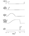
- the voltage v 3 on be pulse forming network 3 rises during the interval t 1 to t 2 to reach the peak value which is related to the supply voltage present at terminals 1 and 2 and the current initially flowing through inductor 4 at the instant t 1 that thyristor 5 is rendered conductive.
- the current i L and the voltage v 3 are shown in lines c and d of Figure 2 respectively.
- the voltage peak to which the pulse forming network is charged is twice the supply voltage under conditions of resonant charge transfer, assuming no losses.
- the time interval t 1 to t 2 is the time taken for the current i L to return resonantly to zero, and it is determined not only by the value of the inductor 4 and the inductance and capacity of the pulse forming network 3, but also by the value of current i L at the instant t,.
- the thyristor 5 becomes reverse biassed, as previously mentioned, and its recovery period commences. When a short period has elapsed to ensure that its recovery is complete, the thyristor 8 is rendered conductive to enable the pulse forming network 3 is discharge through the load 7.
- the pulse forming network 3 discharges very rapidly, and as it does so an output pulse 13 is generated.
- This output pulse 13 is shown in line e of Figure 2 and it commences at time t 3 .
- it has a duration which is very short indeed to the period to to t 2 during which energy is being transferred from the power supply to the pulse forming network 3.
- the pulse can possess an extremely high peak power level - that is to say, the peak current flowing through the load 7 can be very large indeed.
- the three switchable devices 5, 6 and 8 are provided with respective drive circuits 14, 15, 16 under the control of a controller 17.
- Controller 17 is operative to monitor the voltage level at terminall which is provided by the d.c. power supply, since the time t o is controlled to compensate for vdtage variations.
- Information as to the required timing t 3 of the output pulse 13 is fed via terminal 18 into the controller 17, which causes the drive circuit 15 to trigger the transistor 6 at a time t 0 which will enable variations in the voltage at terminal 1 to be taken into account.
- the controller 17 causes drive circuit 15 to render transistor 6 non-conductive, and simultaneously causes drive circuit 14 to trigger thyristor 5.
- the drive circuit 16 triggers thyristor 8 under control of the controller 17 to generate an output pulse.
Abstract
A pulse generator is operative to produce a series of very short, high energy pulses by allowing a reactive network to charge periodically from a d.c. power supply over a relatively long interval, and then rapidly discharging the accumulated energy into a load. The generator is intended for use in a radar transmitter. The peak level to which the reactive network charges is dependent on the charging period, and the invention enables the peak level to be controlled by charging the network via an inductor, and allowing the inductor current to build up to a substantial level before charging of the network commences. When the inductor current reaches a required level, it is diverted to the reactive network. In this way a series of high power pulses having uniform peak levels is generated in a very convenient manner.
Description
- This invention relates to pulse circuits which are capable of generating high power pulses of short duration. A circuit of this kind can be used, for example, to provide the operating power for a high power oscillator, such as a magnetron, which forms part of a radar transmitter. Such a pulse circuit is sometimes termed a radar pulse modulator. A radar transmitter commonly transmits pulses having a very low mark-to-space ratio, that is to say, transmitted short pulses are spaced apart in time by relatively long'intervals during which echoes of the pulses are returned by intercepted radar targets to a radar receiver.
- It is customary to use a pulse forming network to generate pulses of the required characteristics. In a pulse forming network,-an array of capacitors and one or more inductors are charged to a required voltage level, and when fully charged the network is discharged, typically into a pulse transformer which raises the voltage to a level (typically 30 kV1 at which it can be used to drive a magnetron oscillator.
- Variations in the level to which the pulse forming network is charged can lead to significant fluctuations in the pulse characteristics, particularly its peak voltage level. These variations are likely to be small but not insignificant in those cases in which the pulse generator is operative to produce a sequence of pulses which are regularly spaced apart in time, but changes in the pulse repetition rate can lead to unpredictable or unacceptably large fluctuations in pulse amplitude. The present invention seeks to provide an improved pulse generator in which this difficulty is reduced in a particularly satisfactory manner.
- According to this invention, a pulse generator includes a pulse forming network having capacitance and inductance; means for resonantly charging the pulse forming network from a supply voltage via an inductor, and for subsequently discharging the pulse forming network to produce an output pulse; and means for establishing current flow through said inductor prior to the instant at which charging of the pulse forming network commences, whereby the peak voltage value to which the pulse forming network is charged is dependent on the magnitude of said current flow at said instant.
- The current flowing through said inductor increases at a predictable rate from zero when the voltage is applied across it. Thus the value of the current flowing through said inductor at the instant at which charging of the pulse forming network is allowed to commence is itself a function of the period for which the current has been flowing. By accurately adjusting this period of time the output voltage value of the pulse forming network can be controlled and hence one can maintain uniformity in the sequence of pulses which is generated. The invention enables compensation to be provided for variation in the voltage level of the power supply from which the pulse generator takes its energy. The power drawn by the pulse generator from the power supply is not steady, but fluctuates in a periodic manner and inevitably the supply voltage will decay somewhat whilst power is being drawn from the power supply, and the supply voltage will then recover towards its nominal value. If the pulse sequence generated by the pulse generator is perfectly regular, then the supply voltage will have recovered to exactly the same level on each occasion that power is drawn from it. However, if the pulse generator is operative to produce an irregular sequence of pulses, the recovery periods of the power supply will not be constant, and dis can lead to variations and irregularities in the voltage and power levels of the pulses which are generated.
- The invention is further described by way of example with reference to the accompanying drawings, in which
- Figure 1 shows a pulse generator in a simplified diagrammatic form, and
- Figure 2 is an explanatory diagram.
- Referring to Figure 1, a.d.c power supply is connected to
terminals 1 and 2 of a pulse generator. Apulse forming network 3 consisting of an array of inductance and capacitance in known manner is connected to the terminal 1 via a charging inductor 4 and a switch which takes the form of atriggerable thyristor 5. Aswitchable transistor 6 is connected betweenterminal 2 and the inductor 4. In operation, thepulse forming network 3 is charged from the power supply connected toterminals 1 and 2, and it is then subsequently discharged into a load 7 when a further switchable thyristor 8 is triggered. - A pulse generator of this kind is particularly suitable for driving a magnetron oscillator which forms part of a radar transmitter. A magnetron oscillator is a relatively efficient source of microwave oscillations, but it requires high voltage pulse (of the order of 30 kV) to operate it - the magnetron oscillates whilst a voltage applied to it exceeds a threshold value. The pulse generator produces pulses at a much lower voltage, typically of the order of 600 volts, and these pulses are fed via a transformer to the magnetron. In Figure 1, the voltage transformer and the magnetron are represented simply as the load 7.
- The operation of the pulse generator shown in Figure 1 is as follows. It is assumed that initially the
pulse forming network 3 is discharged, and that boththyristors 5 and 8 are in their non-conductive states. The sequence of events is illustrated diagrammatically with reference to Figure 2. At time t a pulse 10 (as shown in line a of Figure 21 is fed totransistor 6 which renders it conductive and current iL begins to flow through the inductor 4, and in conventional manner it increases from zero at an approximately linear rate. At time tl,transistor 6 is rendered non-conductive and simultaneously the thyristor 4 is triggered into its conductive state by the application of a trigger pulse 12 (as shown in line b of Figure 2). Thepulse forming network 3 in combination with the inductor 4 behaves as a resonant circuit, so that the pulse forming network is resonantly charged. The technique of resonantly charging a pulse forming network is in itself well known. As thethyristor 5 becomes non-conductive when the current flow through it passes through zero, it behaves as a rectifying device - that is to say, the current charging of thepulse forming network 3 automatically ceases when the current iL returns to zero at time t2. The voltage v3 on bepulse forming network 3 rises during the interval t1 to t2 to reach the peak value which is related to the supply voltage present atterminals 1 and 2 and the current initially flowing through inductor 4 at the instant t1 thatthyristor 5 is rendered conductive. The current iL and the voltage v3 are shown in lines c and d of Figure 2 respectively. In the absence of any current flow through inductor 4 whenthyristor 5 is triggered, the voltage peak to which the pulse forming network is charged is twice the supply voltage under conditions of resonant charge transfer, assuming no losses. - It will thus be apparent that by adjusting the initial time period to to t1 during which the current iL increases, the final charging voltage of the
pulse forming network 3 can be adjusted.The time interval t1 to t2 is the time taken for the current iL to return resonantly to zero, and it is determined not only by the value of the inductor 4 and the inductance and capacity of thepulse forming network 3, but also by the value of current iL at the instant t,. At the time t2' thethyristor 5 becomes reverse biassed, as previously mentioned, and its recovery period commences. When a short period has elapsed to ensure that its recovery is complete, the thyristor 8 is rendered conductive to enable thepulse forming network 3 is discharge through the load 7. Thepulse forming network 3 discharges very rapidly, and as it does so anoutput pulse 13 is generated. Thisoutput pulse 13 is shown in line e of Figure 2 and it commences at time t3. Typically it has a duration which is very short indeed to the period to to t2 during which energy is being transferred from the power supply to thepulse forming network 3. In this way the pulse can possess an extremely high peak power level - that is to say, the peak current flowing through the load 7 can be very large indeed. - It will be apparent that if the
transistor 6 fails to operate, i.e. become conductive, the network voltage will be somewhat less than the required value. However, a voltage surge is not developed under these conditions, and the pulse generator can continue operation, although, of course, its output level is not properly regulated. - The three
switchable devices respective drive circuits controller 17.Controller 17 is operative to monitor the voltage level at terminall which is provided by the d.c. power supply, since the time to is controlled to compensate for vdtage variations. Information as to the required timing t3 of theoutput pulse 13 is fed viaterminal 18 into thecontroller 17, which causes thedrive circuit 15 to trigger thetransistor 6 at a time t0 which will enable variations in the voltage at terminal 1 to be taken into account. Subsequently, at time tl, thecontroller 17 causesdrive circuit 15 to rendertransistor 6 non-conductive, and simultaneously causesdrive circuit 14 to triggerthyristor 5. Finally when time t3 arrives thedrive circuit 16 triggers thyristor 8 under control of thecontroller 17 to generate an output pulse.
Claims (3)
1. A pulse generator including a pulse forming network having capacitance and inductance; means for resonantly charging the pulse forming network from a supply voltage via an inductor, and for subsequently discharging the pulse forming network to produce an output pulse; and means for establishing current flow through said inductor prior to the instant at which charging of the pulse forming retwork commences, whereby the peak voltage value to which the pulse forming network is charged is dependent on the magnitude of said current flow at said instant.
2. A pulse generator as claimed in claim 1 and wherein the magnitude of the current flowing through said inductor at said instant is a function of the time during which current has been flowing at said instant.
3. A pulse generator as claimed in claim 1 or 2 and wherein prior to said instant, the supply voltage is applied across said inductorby the action of a switch connected in series with it, and wherein means are provided for simultaneously rendering said switch non-conductive and rendering conductivea further switch positioned between said inductor and said pulse forming network, so as to direct the established inductor current to charge said pulse forming network.
Applications Claiming Priority (2)
| Application Number | Priority Date | Filing Date | Title |
|---|---|---|---|
| GB8124318 | 1981-08-08 | ||
| GB08124318A GB2104326B (en) | 1981-08-08 | 1981-08-08 | A pulse generator |
Publications (2)
| Publication Number | Publication Date |
|---|---|
| EP0072153A2 true EP0072153A2 (en) | 1983-02-16 |
| EP0072153A3 EP0072153A3 (en) | 1983-10-12 |
Family
ID=10523816
Family Applications (1)
| Application Number | Title | Priority Date | Filing Date |
|---|---|---|---|
| EP82304005A Ceased EP0072153A3 (en) | 1981-08-08 | 1982-07-29 | A generator of short duration high power pulses |
Country Status (2)
| Country | Link |
|---|---|
| EP (1) | EP0072153A3 (en) |
| GB (1) | GB2104326B (en) |
Cited By (13)
| Publication number | Priority date | Publication date | Assignee | Title |
|---|---|---|---|---|
| EP0194520A2 (en) * | 1985-02-28 | 1986-09-17 | SELENIA INDUSTRIE ELETTRONICHE ASSOCIATE S.p.A. | Voltage regulator for line modulators for use in transmitters for radar applications |
| EP0427469A2 (en) * | 1989-11-06 | 1991-05-15 | Raytheon Company | Radar system |
| FR2658011A1 (en) * | 1990-02-08 | 1991-08-09 | Commissariat Energie Atomique | POWER SUPPLY DEVICE FOR ONE OR MORE METAL STEAM LASERS. |
| US5202894A (en) * | 1990-02-08 | 1993-04-13 | Commissariat A L'energie Atomique | Electric supply device for one or more metal vapor lasers using an electric power charging circuit with a variable inductor to provide a variable charging gradient |
| US9071872B2 (en) | 2003-01-30 | 2015-06-30 | Rovi Guides, Inc. | Interactive television systems with digital video recording and adjustable reminders |
| US9075861B2 (en) | 2006-03-06 | 2015-07-07 | Veveo, Inc. | Methods and systems for segmenting relative user preferences into fine-grain and coarse-grain collections |
| US9166714B2 (en) | 2009-09-11 | 2015-10-20 | Veveo, Inc. | Method of and system for presenting enriched video viewing analytics |
| US9191719B2 (en) | 2003-11-06 | 2015-11-17 | Rovi Guides, Inc. | Systems and methods for providing program suggestions in an interactive television program guide |
| US9294799B2 (en) | 2000-10-11 | 2016-03-22 | Rovi Guides, Inc. | Systems and methods for providing storage of data on servers in an on-demand media delivery system |
| US9326025B2 (en) | 2007-03-09 | 2016-04-26 | Rovi Technologies Corporation | Media content search results ranked by popularity |
| US9749693B2 (en) | 2006-03-24 | 2017-08-29 | Rovi Guides, Inc. | Interactive media guidance application with intelligent navigation and display features |
| US10063934B2 (en) | 2008-11-25 | 2018-08-28 | Rovi Technologies Corporation | Reducing unicast session duration with restart TV |
| US10075746B2 (en) | 1998-07-14 | 2018-09-11 | Rovi Guides, Inc. | Client-server based interactive television guide with server recording |
Families Citing this family (9)
| Publication number | Priority date | Publication date | Assignee | Title |
|---|---|---|---|---|
| GB2183945B (en) * | 1983-12-28 | 1988-08-24 | Senichi Masuda | Pulse-charging type electric dust collecting apparatus |
| DE3447719A1 (en) * | 1983-12-28 | 1985-07-11 | Senichi Tokio/Tokyo Masuda | HIGH-VOLTAGE PULSE SOURCE AND ELECTRICAL DUST SEPARATOR EQUIPPED WITH IT WITH PULSE CHARGE |
| DE3347229A1 (en) * | 1983-12-28 | 1985-07-18 | Ludger Dr.-Ing. 5628 Heiligenhaus Mense | CIRCUIT ARRANGEMENT FOR STROBOSCOPE |
| US6769128B1 (en) | 1995-06-07 | 2004-07-27 | United Video Properties, Inc. | Electronic television program guide schedule system and method with data feed access |
| US8850477B2 (en) | 1995-10-02 | 2014-09-30 | Starsight Telecast, Inc. | Systems and methods for linking television viewers with advertisers and broadcasters |
| US6469753B1 (en) | 1996-05-03 | 2002-10-22 | Starsight Telecast, Inc. | Information system |
| BRPI9812104B1 (en) | 1997-07-21 | 2016-12-27 | Guide E Inc | method for navigating an interactive program guide |
| US6898762B2 (en) | 1998-08-21 | 2005-05-24 | United Video Properties, Inc. | Client-server electronic program guide |
| US8805418B2 (en) | 2011-12-23 | 2014-08-12 | United Video Properties, Inc. | Methods and systems for performing actions based on location-based rules |
Citations (3)
| Publication number | Priority date | Publication date | Assignee | Title |
|---|---|---|---|---|
| FR1341156A (en) * | 1961-12-14 | 1963-10-25 | Ass Elect Ind | Improvements to pulse generators |
| US3127573A (en) * | 1959-05-19 | 1964-03-31 | Raytheon Co | Pulsing circuit with return of energy to source |
| US3139585A (en) * | 1962-06-26 | 1964-06-30 | Ling Temco Vought Inc | Voltage controlling circuit for line type modulator with means feeding back excess power to source |
-
1981
- 1981-08-08 GB GB08124318A patent/GB2104326B/en not_active Expired
-
1982
- 1982-07-29 EP EP82304005A patent/EP0072153A3/en not_active Ceased
Patent Citations (3)
| Publication number | Priority date | Publication date | Assignee | Title |
|---|---|---|---|---|
| US3127573A (en) * | 1959-05-19 | 1964-03-31 | Raytheon Co | Pulsing circuit with return of energy to source |
| FR1341156A (en) * | 1961-12-14 | 1963-10-25 | Ass Elect Ind | Improvements to pulse generators |
| US3139585A (en) * | 1962-06-26 | 1964-06-30 | Ling Temco Vought Inc | Voltage controlling circuit for line type modulator with means feeding back excess power to source |
Cited By (23)
| Publication number | Priority date | Publication date | Assignee | Title |
|---|---|---|---|---|
| EP0194520A3 (en) * | 1985-02-28 | 1988-11-30 | Selenia Industrie Elettroniche Associate S.P.A. | Voltage regulator for line modulators for use in transmitters for radar applications |
| EP0194520A2 (en) * | 1985-02-28 | 1986-09-17 | SELENIA INDUSTRIE ELETTRONICHE ASSOCIATE S.p.A. | Voltage regulator for line modulators for use in transmitters for radar applications |
| EP0427469A2 (en) * | 1989-11-06 | 1991-05-15 | Raytheon Company | Radar system |
| EP0427469A3 (en) * | 1989-11-06 | 1992-05-20 | Raytheon Company | Radar system |
| FR2658011A1 (en) * | 1990-02-08 | 1991-08-09 | Commissariat Energie Atomique | POWER SUPPLY DEVICE FOR ONE OR MORE METAL STEAM LASERS. |
| EP0444986A1 (en) * | 1990-02-08 | 1991-09-04 | Commissariat A L'energie Atomique | Electrical power supply device for one or several metal vapor lasers |
| US5202894A (en) * | 1990-02-08 | 1993-04-13 | Commissariat A L'energie Atomique | Electric supply device for one or more metal vapor lasers using an electric power charging circuit with a variable inductor to provide a variable charging gradient |
| US10075746B2 (en) | 1998-07-14 | 2018-09-11 | Rovi Guides, Inc. | Client-server based interactive television guide with server recording |
| US9294799B2 (en) | 2000-10-11 | 2016-03-22 | Rovi Guides, Inc. | Systems and methods for providing storage of data on servers in an on-demand media delivery system |
| US9369741B2 (en) | 2003-01-30 | 2016-06-14 | Rovi Guides, Inc. | Interactive television systems with digital video recording and adjustable reminders |
| US9071872B2 (en) | 2003-01-30 | 2015-06-30 | Rovi Guides, Inc. | Interactive television systems with digital video recording and adjustable reminders |
| US10986407B2 (en) | 2003-11-06 | 2021-04-20 | Rovi Guides, Inc. | Systems and methods for providing program suggestions in an interactive television program guide |
| US9191719B2 (en) | 2003-11-06 | 2015-11-17 | Rovi Guides, Inc. | Systems and methods for providing program suggestions in an interactive television program guide |
| US10880607B2 (en) | 2003-11-06 | 2020-12-29 | Rovi Guides, Inc. | Systems and methods for providing program suggestions in an interactive television program guide |
| US9092503B2 (en) | 2006-03-06 | 2015-07-28 | Veveo, Inc. | Methods and systems for selecting and presenting content based on dynamically identifying microgenres associated with the content |
| US10984037B2 (en) | 2006-03-06 | 2021-04-20 | Veveo, Inc. | Methods and systems for selecting and presenting content on a first system based on user preferences learned on a second system |
| US9075861B2 (en) | 2006-03-06 | 2015-07-07 | Veveo, Inc. | Methods and systems for segmenting relative user preferences into fine-grain and coarse-grain collections |
| US9128987B2 (en) | 2006-03-06 | 2015-09-08 | Veveo, Inc. | Methods and systems for selecting and presenting content based on a comparison of preference signatures from multiple users |
| US9749693B2 (en) | 2006-03-24 | 2017-08-29 | Rovi Guides, Inc. | Interactive media guidance application with intelligent navigation and display features |
| US10694256B2 (en) | 2007-03-09 | 2020-06-23 | Rovi Technologies Corporation | Media content search results ranked by popularity |
| US9326025B2 (en) | 2007-03-09 | 2016-04-26 | Rovi Technologies Corporation | Media content search results ranked by popularity |
| US10063934B2 (en) | 2008-11-25 | 2018-08-28 | Rovi Technologies Corporation | Reducing unicast session duration with restart TV |
| US9166714B2 (en) | 2009-09-11 | 2015-10-20 | Veveo, Inc. | Method of and system for presenting enriched video viewing analytics |
Also Published As
| Publication number | Publication date |
|---|---|
| EP0072153A3 (en) | 1983-10-12 |
| GB2104326B (en) | 1984-11-21 |
| GB2104326A (en) | 1983-03-02 |
Similar Documents
| Publication | Publication Date | Title |
|---|---|---|
| EP0072153A2 (en) | A generator of short duration high power pulses | |
| US3363184A (en) | Power scavenging deq'ing circuit for a line-type pulser | |
| US3900786A (en) | High voltage pulse generating circuit | |
| US3339108A (en) | Capacitor charging and discharging circuitry | |
| US4648093A (en) | Power supply for gas discharge lasers | |
| US4473875A (en) | Inductive storage pulse circuit device | |
| US3171040A (en) | Fast charging circuit for pulse networks | |
| US3860864A (en) | Power supply circuits | |
| US2782867A (en) | Pulser circuit | |
| US3881145A (en) | Pulse generating device for radar transmitting system | |
| US4051439A (en) | Short pulse magnetron transmitter | |
| US3427501A (en) | Capacitor linear charging power supply | |
| US5969439A (en) | Pulse generator apparatus for RF pulse generation in tuned loads including series regulation and capacitor clamping method therefor | |
| US4763045A (en) | Spark ignitor generated by capacitor discharge synchronized with alternate current power frequency | |
| US3265991A (en) | Silicon controlled rectifier chopper circuit | |
| US5528180A (en) | Steerable pulse phase controller | |
| US4755740A (en) | Circuit for power pulse amplitude stabilization in radar transmitter pulse modulator or the like | |
| US3303385A (en) | Ignition unit | |
| US3566150A (en) | Impulse generator circuit for the control of rectifiers | |
| US3432679A (en) | Magnetic pulse modulator | |
| US2809286A (en) | Pulse transmitter systems | |
| US3886486A (en) | Oscillator circuit for generating an output signal having successive cycles which unidirectionally vary in frequency | |
| CA1081782A (en) | High voltage nanosecond pulser using a repetitive series interrupter | |
| US3716798A (en) | Anticipatory charging regulator | |
| US2485608A (en) | Pulse modulator |
Legal Events
| Date | Code | Title | Description |
|---|---|---|---|
| PUAI | Public reference made under article 153(3) epc to a published international application that has entered the european phase |
Free format text: ORIGINAL CODE: 0009012 |
|
| AK | Designated contracting states |
Designated state(s): AT BE CH DE FR IT LI LU NL SE |
|
| PUAL | Search report despatched |
Free format text: ORIGINAL CODE: 0009013 |
|
| AK | Designated contracting states |
Designated state(s): AT BE CH DE FR IT LI LU NL SE |
|
| 17P | Request for examination filed |
Effective date: 19831219 |
|
| STAA | Information on the status of an ep patent application or granted ep patent |
Free format text: STATUS: THE APPLICATION HAS BEEN REFUSED |
|
| 18R | Application refused |
Effective date: 19860412 |
|
| RIN1 | Information on inventor provided before grant (corrected) |
Inventor name: RICHARDSON, ROBERT |