EP0078457A2 - Method and apparatus for the temporary increase of the absorption rate of transmitting optical devices - Google Patents
Method and apparatus for the temporary increase of the absorption rate of transmitting optical devices Download PDFInfo
- Publication number
- EP0078457A2 EP0078457A2 EP82109720A EP82109720A EP0078457A2 EP 0078457 A2 EP0078457 A2 EP 0078457A2 EP 82109720 A EP82109720 A EP 82109720A EP 82109720 A EP82109720 A EP 82109720A EP 0078457 A2 EP0078457 A2 EP 0078457A2
- Authority
- EP
- European Patent Office
- Prior art keywords
- flip
- counter
- flop circuit
- arrangement according
- current sources
- Prior art date
- Legal status (The legal status is an assumption and is not a legal conclusion. Google has not performed a legal analysis and makes no representation as to the accuracy of the status listed.)
- Granted
Links
Images
Classifications
-
- G—PHYSICS
- G02—OPTICS
- G02F—OPTICAL DEVICES OR ARRANGEMENTS FOR THE CONTROL OF LIGHT BY MODIFICATION OF THE OPTICAL PROPERTIES OF THE MEDIA OF THE ELEMENTS INVOLVED THEREIN; NON-LINEAR OPTICS; FREQUENCY-CHANGING OF LIGHT; OPTICAL LOGIC ELEMENTS; OPTICAL ANALOGUE/DIGITAL CONVERTERS
- G02F1/00—Devices or arrangements for the control of the intensity, colour, phase, polarisation or direction of light arriving from an independent light source, e.g. switching, gating or modulating; Non-linear optics
- G02F1/01—Devices or arrangements for the control of the intensity, colour, phase, polarisation or direction of light arriving from an independent light source, e.g. switching, gating or modulating; Non-linear optics for the control of the intensity, phase, polarisation or colour
- G02F1/15—Devices or arrangements for the control of the intensity, colour, phase, polarisation or direction of light arriving from an independent light source, e.g. switching, gating or modulating; Non-linear optics for the control of the intensity, phase, polarisation or colour based on an electrochromic effect
- G02F1/163—Operation of electrochromic cells, e.g. electrodeposition cells; Circuit arrangements therefor
Definitions
- the invention relates to a method and a device for temporarily increasing the degree of absorption of transmitting optical components, preferably of lenses and filters.
- transmissive optical components with a variable degree of absorption are used.
- a well-known example is eyeglass lenses, which are also supposed to act as sun protection glasses at times.
- So-called phototropic glasses are known for this, which become darker in bright sunlight due to its UV component and thereby protect the eye from excessive or uncomfortable brightness.
- these phototropic glasses have the disadvantage that the change in the degree of absorption takes place too slowly and that they function insufficiently behind the windshields of cars.
- Transmitting optical components with a temporarily variable degree of absorption are also advantageous for numerous optical devices. So it is e.g. often necessary to temporarily weaken a beam path in a defined manner. So-called gray or neutral filters are used for this, which are usually brought into the beam path by mechanical means. The disadvantage in this case is that automation is complex and prone to failure due to the mechanically moving parts.
- the invention is therefore based on the object of specifying a method and a device with which it is possible to temporarily increase the degree of absorption of transmitting optical components, preferably of lenses and filters, with sufficient speed, without having to move mechanical parts and without to be dependent on special environmental conditions (such as with phototropic glasses).
- an electrochromic layer is applied to the optical component, to which a defined amount of charge is supplied to increase the degree of absorption and which is removed from a defined amount of charge to restore the initial state.
- An advantageous embodiment of the invention is characterized in that the color and decolorization process is started via a flip-flop circuit, that during a color or decolorization process the electrochromic layer is supplied or discharged with charges from two delimitable current sources and counting pulses from a clock generator to a counter are given, and that the counter switches off the color or decolorization process when reaching defined values via the flip-flop circuit.
- An advantageous embodiment is characterized in that the electrochromic layer is connected to two delimitable current sources, via which charges are supplied or discharged, that the switching inputs of the current sources are connected via gates to the outputs of a flip-flop circuit and to the most significant output of a counter, that the flip-flop circuit is connected via an edge differentiator to the second most significant output of the counter, that the output of the flip-flop circuit is connected to a clock generator which gives counting pulses to the counter during a color or decolorization process and that the flip-flop circuit has a key for triggering a color - or decolorization process is connected.
- the decolorization stream is smaller than the coloring stream, which takes into account the fact that more charges are required for dyeing in an electrochromic layer than can be removed during decolorization.
- transistors are provided for the current sources, which are controlled via base resistors in an emitter circuit.
- the button for triggering the color or decolorization process is expedient to design the button for triggering the color or decolorization process as a touch sensor and the electronic components in thick-film technology or a higher integrating technique.
- they can then be installed in the glasses frame together with the batteries required for the power supply.
- the dyeing or decolorization process is triggered by an optical sensor, with a circuit which is subject to hysteresis preventing the dyeing state from being changed too frequently in the event of fluctuations around the switching point.
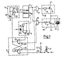
- 11 denotes the electrochromic layer which is applied to a lens or another optical component.
- the electrode 12 of the electrochromic layer is at zero potential, the electrode 13 is connected to the current sources 18 and 19.
- the delimitable current sources 18 and 19 consist of the PNP transistor 14 and the NPN transistor 15, the emitters of which are connected to a positive and a negative voltage source and whose common connection point is connected to the electrochromic layer.
- the transistors 14 and 15 are controlled via the base resistors 16 and 17, the size of which limits the charge or discharge current for the layer, if necessary, via the current amplification of the transistors alone. During the coloring, the NPN transistor 15 is turned on; when decoloring the PNP transistor 14.
- Color or decolorization current for the electrochromic layer 11 are and switched off by the link by means of the NAND gate 31 or the NOR gate 32 of the output value of the counter 2 and the state of the flip-flop 3.
- the counter 2 is connected to the clock generator 5, in which the clock signal on which the charge control is based is generated by the capacitor 51, the resistor 52 and the Schmitt trigger NAND gate 53.
- the arrangement shown in Fig. 1 also includes a flank differentiator 6 for ending and the button 41 for triggering a dyeing or decoloring process.
- the counter 2 After switching on the voltage supply, not shown, the counter 2 is first - with a known device, not shown in the drawing - with its most significant output Q 11 to "1" or "H 'and with all other outputs to" 0 ⁇ "or "L.” This state characterizes the completely colored state of the layer, which is initially assumed after the power supply is switched on, so that the electrochromic layer is completely decolored, regardless of the state in which it happens to be Gates 31 and 32 of the Q 11 associated input to 'H'.
- the flip-flop 3 consisting of the cross-connected NOR gates 33 and 34 can assume two different states, which are characterized, for example, at the node 36 by "L” or "H".
- the circuit point 35 always has the inverted state. If the circuit point 36 is "0 ⁇ ", the electrochromic layer is not changed. After switching on the power supply, either of the two states can exist. If "H” is present, then both inputs of NAND gate 31 are at H and the layer is immediately decolorized via transistor 14. If "0 ⁇ ” is present, then the first actuation of the button 41 at the output of the NOR gate 34 causes the state "0 ⁇ ” and thus also to "0 ⁇ ” at the corresponding input of the NOR gate 33.
- the clock generator is also active and sends counting pulses to the counter 2. This counts up until all outputs have the value "1". With the next count pulse, all outputs assume the value "0 ⁇ ".
- the second most significant output Q 10 changes from “1" to "0 ⁇ ”.
- This negative edge is differentiated by the edge differentiating element (6) consisting of inverter 61, capacitor 63 and NOR gate 62, and a short “H” pulse is thereby generated at the output of NOR gate 62.
- the clock generator 5 is stopped and the current source 18 becomes passive.
- the counter status with all outputs at "0 ⁇ ” thus represents the decolorized status of the layer.
- the second most significant output Q 10 thus changes from "1" to "0 ⁇ " for the first time since the dyeing process began.
- the edge differentiator 6 there is again a short "H” signal, which resets the flip-flop 3 and thus switches off the coloring process and the clock generator 5.
- the system is idle again.
- the next actuation of the button 41 again triggers a decolorization process since the output Q 11 of the counter 2 is again at "H".
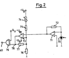
- FIG. 2 A particularly advantageous further embodiment of the invention, which is connected to the switching point 40 instead of the button 41 and the resistor 42, is shown in FIG. 2.
- the condition of the electrochromic layer is automatically set as a function of the brightness measured by an optical sensor 70.
- the sensor can be a pin diode or a photo transistor, for example.
- Its signal is first amplified by the operational amplifier 71 connected to the resistor 72.
- the following operational amplifier 73 is connected as a comparator, a hysteresis behavior being achieved by loading the voltage divider consisting of resistors 74 to 76 through the comparator output via resistor 77.
- the hysteresis and thus the switching threshold can be set with the resistor 74.
- the switching threshold U is given by and the width of the hysteresis ⁇ ⁇ U
- the comparator output signal at node 78 is "H 'if the layer is to be colored, otherwise” L ". It is therefore replaced by the most significant output signal Q 11 of counter 2, which, as described above, indicates the coloring state of the layer Exclusive OR gate 79. Its output is only at "H” and thus triggers a color or decolorization process if the output signal of the comparator does not match the most significant output of the counter 2.
- a preferred area of application for the arrangements described is sun protection glasses, in particular those with an optical effect. It is advantageous for spectacle wearers if the spectacles are also sunglasses to correct the ametropia.
- the arrangements described have the advantage over the previously known phototropic glasses that the electrochromic layers are colored and decolored much more quickly. They also work behind the windshields of cars.
- the glasses can be equipped with a switch for triggering the color or decolorization processes. This can e.g. be designed as a touch sensor that sits at the beginning of a bracket.
- the entire electronic arrangement is expediently carried out using thick-film technology or a higher integrating technology, so that it can be accommodated in the spectacle frame together with the batteries required for the power supply.
- the current consumption if no color or decolorization process takes place, is so low that the battery voltage can be switched off during the time when the glasses are not being used.
- optical devices in which a beam path must be temporarily weakened in a defined manner.
- microscopes for example, there is a desire that the image have approximately the same brightness even at different magnifications.
- a plane-parallel glass plate with an electrochromic layer is placed at a suitable point in the microscope beam path and its degree of absorption is changed using one of the arrangements described.
- the momentary button can be operated directly by the magnification changer or by the nosepiece.
- the automatic switchover described with FIG. 2 is by an optical sensor particularly advantageous.
- the electrochromic layer can also be applied to an existing optical part.
- optical arrangements can also be considered, in which a required different reflectivity can be replaced by a different absorption capacity.
- Dimmable car rear-view mirrors are an example.
- the known version consists of a glass plate and a mirror arranged behind it, which is folded away in the event of excessive light.
- this solution has disadvantages: the mirror must be folded away by hand, which is only possible with little mechanical effort in the case of interior mirrors. Automation is only possible with relatively great effort.
- a different reflectivity can also be achieved by a (fixed) mirrored glass plate on the back, on the front of which an electrochromic layer is applied.
- a temporary dimming effect can be achieved by pressing a button, which is particularly advantageous for exterior mirrors; but also generally has the advantage that the button can be placed completely independently of the mirror.
- the fade-in or fade-in is carried out automatically, so that the driver is relieved of all operations.
Abstract
Description
Die Erfindung betrifft ein Verfahren und eine Vorrichtung zur zeitweisen Erhöhung des Absorptionsgrades von transmittierenden optischen Bauelementen, vorzugsweise von Linsen und Filtern.The invention relates to a method and a device for temporarily increasing the degree of absorption of transmitting optical components, preferably of lenses and filters.
In vielen Gebieten der Optik werden transmittierende optische Bauelemente mit veränderbaren Absorptionsgrad verwendet. Ein bekanntes Beispiel sind Brillenlinsen, die zeitweise auch als Sonnenschutzgläser wirken sollen. Dafür sind sogenannte phototrope Gläser bekannt, die im hellen Sonnenlicht durch dessen UV-Anteil dunkler werden und dadurch das Auge vor zu großer oder unangenehmer Helligkeit schützen. Diese phototropen Gläser haben jedoch den Nachteil, daß die Änderung des Absorptionsgrades zu langsam erfolgt und-daß sie hinter den Windschutzscheiben von Autos ungenügend funktionieren.In many areas of optics, transmissive optical components with a variable degree of absorption are used. A well-known example is eyeglass lenses, which are also supposed to act as sun protection glasses at times. So-called phototropic glasses are known for this, which become darker in bright sunlight due to its UV component and thereby protect the eye from excessive or uncomfortable brightness. However, these phototropic glasses have the disadvantage that the change in the degree of absorption takes place too slowly and that they function insufficiently behind the windshields of cars.
Transmittierende optische Bauelemente mit zeitweise veränderlichem Absorptionsgrad sind ferner für zahlreiche optische Geräte vorteilhaft. So ist es z.B. oft notwendig, einen Strahlengang zeitweise definiert zu schwachen. Hierfür werden, sog. Grau- oder Neutralfilter verwendet, welche meist mit mechanischen Mitteln in den Strahlengang gebracht werden. Nachteilig ist in diesem Fall, daß eine Automatisierung aufwendig und durch die mechanisch bewegten Teile störanfällig ist.Transmitting optical components with a temporarily variable degree of absorption are also advantageous for numerous optical devices. So it is e.g. often necessary to temporarily weaken a beam path in a defined manner. So-called gray or neutral filters are used for this, which are usually brought into the beam path by mechanical means. The disadvantage in this case is that automation is complex and prone to failure due to the mechanically moving parts.
Der Erfindung liegt daher die Aufgabe zugrunde, 'ein Verfahren und eine Vorrichtung anzugeben, mit der es möglich ist, den Absorptionsgrad von transmittierenden optischen Bauelementen, vorzugsweise von Linsen und Filtern zeitweise mit ausreichender Geschwindigkeit definiert zu erhöhen, ohne mechanische Teile bewegen zu müssen und ohne auf besondere Umweltbedingungen (wie bei phototropen Gläsern) angewiesen zu sein.The invention is therefore based on the object of specifying a method and a device with which it is possible to temporarily increase the degree of absorption of transmitting optical components, preferably of lenses and filters, with sufficient speed, without having to move mechanical parts and without to be dependent on special environmental conditions (such as with phototropic glasses).
Die gestellte Aufgabe wird gemäß der vorliegenden Erfindung dadurch gelöst, daß auf das optische Bauelement eine elektrochrome Schicht aufgebracht ist, der zur Erhöhung des Absorptionsgrades eine definierte Ladungsmenge zugeführt wird und der zur Wiederherstellung des Ausgangszustandes eine definierte Ladungsmenge entzogen wird. 1 P 925 EP Eine zweckmäßige Ausgestaltung der Erfindung zeichnet sich dadurch aus, daß der Farbe und Entfärbevorgang über eine Flipflopschaltung gestartet wird, daß während eines Farbe- oder Entfärbevorganges der elektrochromen Schicht von zwei begrenzbaren Stromquellen Ladungen zu- bzw. abgeführt werden und von einem Taktgenerator Zählimpulse an einen Zähler gegeben werden, und daß der Zähler beim Erreichen definierter Werte über die Flipflopschaltung den Farbe- oder Entfärbevorgang abschaltet.The object is achieved according to the present invention in that an electrochromic layer is applied to the optical component, to which a defined amount of charge is supplied to increase the degree of absorption and which is removed from a defined amount of charge to restore the initial state. 1 P 925 EP An advantageous embodiment of the invention is characterized in that the color and decolorization process is started via a flip-flop circuit, that during a color or decolorization process the electrochromic layer is supplied or discharged with charges from two delimitable current sources and counting pulses from a clock generator to a counter are given, and that the counter switches off the color or decolorization process when reaching defined values via the flip-flop circuit.
Eine vorteilhafte Ausführungsform zeichnet sich dadurch aus, daß die elektrochrome Schicht mit zwei begrenzbaren Stromquellen verbunden ist Ober welche Ladungen zu- bzw. abgeführt werden, daß die Schalteingänge der Stromquellen über Gatter mit den Ausgängen einer Flipflopschaltung und mit dem höchstwertigen Ausgang eines Zählers verbunden sind, daß die Flipflopschaltung über ein Flankendifferenzierglied mit dem zweithöchstwertigen Ausgang des Zählers verbunden ist, daß der Ausgang der Flipflopschaltung mit einem Taktgenerator verbunden ist, welcher während eines Farbe- bzw. Entfärbevorganges Zählimpulse an den Zähler gibt und daß die Flipflopschaltung mit einer Taste zum Auslösen eines Färbe- bzw. Entfärbevorganges verbunden ist.An advantageous embodiment is characterized in that the electrochromic layer is connected to two delimitable current sources, via which charges are supplied or discharged, that the switching inputs of the current sources are connected via gates to the outputs of a flip-flop circuit and to the most significant output of a counter, that the flip-flop circuit is connected via an edge differentiator to the second most significant output of the counter, that the output of the flip-flop circuit is connected to a clock generator which gives counting pulses to the counter during a color or decolorization process and that the flip-flop circuit has a key for triggering a color - or decolorization process is connected.
Die bisher nur für Anzeigeelemente bekannten elektrochromen Schichten verbrauchen nur während einer Änderung ihres Absorptionsgrades Strom, was insbesondere bei nicht stationären Geräten, wie z.B. Sonnenbrillen, ein Vorteil ist.The electrochromic layers previously known only for display elements only consume electricity during a change in their degree of absorption, which is particularly the case with non-stationary devices, such as e.g. Sunglasses are an advantage.
In einer weiteren Ausführungsform der Erfindung ist der Entfärbestrom kleiner als der Färbestrom, womit der Tatsache Rechnung getragen wird, daß bei einer elektrochromen Schicht zum Färben mehr Ladungen benötigt werden als beim Entfärben ausgeräumt werden können.In a further embodiment of the invention, the decolorization stream is smaller than the coloring stream, which takes into account the fact that more charges are required for dyeing in an electrochromic layer than can be removed during decolorization.
In einer bevorzugten Ausführungsform sind für die Stromquellen Transistoren vorgesehen, die über Basiswiderstände in Emitterschaltung angesteuert werden.In a preferred embodiment, transistors are provided for the current sources, which are controlled via base resistors in an emitter circuit.
Insbesondere für die Verwendung bei Brillen ist es zweckmäßig, die Taste zum Auslösen des Farbe- oder Entfärbevorganges als Berührungssensor auszubilden und die elektronischen Bauelemente in Dickschichttechnik oder einer höher integrierenden Technik auszuführen. Bei Brillen können sie dann zusammen mit den zur Stromversorgung notwendigen Batterien in die Brillenfassung eingebaut werden.In particular for use with glasses, it is expedient to design the button for triggering the color or decolorization process as a touch sensor and the electronic components in thick-film technology or a higher integrating technique. With glasses, they can then be installed in the glasses frame together with the batteries required for the power supply.
In einer besonders vorteilhaften Ausführungsform wird der Färbe- bzw. Entfärbevorgang durch einen optischen Sensor ausgelöst, wobei durch eine mit Hysterese behaftete Schaltung ein zu häufiges Wechseln des Färbezustandes bei Schwankungen um den Schaltpunkt vermieden wird.In a particularly advantageous embodiment, the dyeing or decolorization process is triggered by an optical sensor, with a circuit which is subject to hysteresis preventing the dyeing state from being changed too frequently in the event of fluctuations around the switching point.
)Weitere Ausgestaltungen der Erfindung gehen aus den Unteransprüchen hervor.) Further embodiments of the invention emerge from the subclaims.
Die Erfindung wird im folgenden anhand der Figuren 1 und 2 näher erläutert. Dabei zeigen i
- Fig. 1 ein Ausführungsbeispiel für die Anordnung zur Ladungszu- bzw. abfuhr für den Farbe- bzw. Entfarbevorgang, wobei die Vorgänge durch eine Taste ausgelöst werden, und
- Fig. 2 ein Ausführungsbeispiel für die Auslösung der Färbevorgänge durch einen optischen Sensor.
- Fig. 1 shows an embodiment of the arrangement for the charge supply or discharge for the color or decolorization process, the processes being triggered by a button, and
- Fig. 2 shows an embodiment for triggering the dyeing processes by an optical sensor.
In Fig. 1 ist mit 11 die elektrochrome Schicht bezeichnet, welche auf eine Linse oder ein anderes optisches Bauelement aufgebracht ist. Die Elektrode 12 der elektrochromen Schicht liegt auf Nullpotential, die Elektrode 13 ist mit den Stromquellen 18 und 19 verbunden. Die begrenzbaren Stromquellen 18 und 19 bestehen aus dem PNP-Transistor 14 und dem NPN-Transistor 15, deren Emitter mit einer positiven und einer negativen Spannungsquelle verbunden sind und deren gemeinsamer Verbindungspunkt mit der elektrochromen Schicht verbunden ist. Die Transistoren 14-und 15 werden über die Basiswiderstönde 16 und 17 angesteuert, deren Größe über die Stromverstärkung der Transistoren alleine den Lade- bzw. Entladestrom für die Schicht im Bedarfsfall begrenzt. Während des Färbens wird der NPN-Transistor 15 durchgesteuert; beim Entfärben der PNP-Transistor 14.In Fig. 1, 11 denotes the electrochromic layer which is applied to a lens or another optical component. The
Farbe- bzw. Entfärbestrom für die elektrochrome Schicht 11 werden ein-und ausgeschaltet durch die Verknüpfung mittels des NAND-Gatters 31 bzw. des NOR-Gatt-ers 32 von Ausgangswert des Zählers 2 und Zustand des Flipflops 3.Color or decolorization current for the electrochromic layer 11 are and switched off by the link by means of the
Der Zähler 2 ist mit dem Taktgenerator 5 verbunden, in dem das der Ladungssteuerung zugrunde liegende Taktsignal durch den Kondensator 51, den Widerstand 52 und das Schmitt-Trigger-NAND-Gatter 53 erzeugt wird. Die in Fig. 1 gezeigte Anordnung enthält ferner ein Flankendifferenzierglied 6 zum Beenden und den Taster 41 zum Auslösen eines Färbe- bzw. Entfärbevorganges.The counter 2 is connected to the
Nach dem Einschalten der nicht gezeichneten Spannungsversorgung wird zunächst der Zähler 2 - mit einer bekannten, in der Zeichnung nicht dargestellten Einrichtung - mit seinem höchstwertigen Ausgang Q11 auf "1" bzw. "H' und mit allen anderen Ausängen auf "0̸" bzw. "L" gesetzt. Dieser Zustand charakterisiert den völlig gefärbten Zustand der Schicht; er wird nach dem Einschalten der Spannungsversorgung zunächst einmal angenommen, damit die elektrochrome Schicht -unabhängig von dem Zustand in dem sie sich zufällig befindet - vollständig entfärbt wird. Damit liegt an den Gattern 31 und 32 der Q11 zugehörige Eingang auf 'H'.After switching on the voltage supply, not shown, the counter 2 is first - with a known device, not shown in the drawing - with its most significant output Q 11 to "1" or "H 'and with all other outputs to" 0̸ "or "L." This state characterizes the completely colored state of the layer, which is initially assumed after the power supply is switched on, so that the electrochromic layer is completely decolored, regardless of the state in which it happens to be Gates 31 and 32 of the Q 11 associated input to 'H'.
Das Flipflop 3 bestehend aus den über Kreuz geschalteten NOR-Gattern 33 und 34 kann zwei verschiedene Zustände annehmen die z.B. am Schaltungspunkt 36 durch "L" oder "H" charaktertsiert sind. Dabei hat der Schaltungspunkt 35 immer den invertierten Zustand. Liegt am Schaltungspunkt 36 "0̸", dann wird die elektrochrome Schicht nicht verändert. Nach dem Einschalten der Stromversorgung kann Jeder der beiden Zustände vorliegen. Liegt "H" vor, dann liegen beide Eingänge des NAND-Gatters 31 auf H und die Schicht wird Ober den Transistor 14 sofort entfärbt. Liegt "0̸" vor, dann bewirkt die erste Betätigung des Tasters 41 am Ausgang des NOR-Gatters 34 den Zustand "0̸" und damit auch zu "0̸" am entsprechenden Eingang des NOR-Gatters 33. Da der zweite Eingang dieses Gatters so lange der Zähler 2 nicht läuft immer "0̸" ist, entsteht om Ausgang "1"· und somit am Schaltungspunkt 36 "H". Dieser Zustand bleibt zunächst unabhängig von weiteren Änderungen am Taster 41. Wenn also beim Einschalten der Stromversorgung die Schicht nicht sofort entfärbt wird und damit eine Betätigung des Tasters 41 wirkungslos bleibt, bewirkt die erste Betätigung des Tasters 41 einen Entfärbevorgang.The flip-flop 3 consisting of the
Wenn der Schaltungspunkt 36 auf "H" liegt, ist auch der Taktgenerator aktiv und gibt Zählimpulse an den Zähler 2. Dieser zählt aufwärts, bis alle Ausgänge den Wert "1" haben. Beim nächsten Zählimpuls nehmen alle Ausgänge den Wert "0̸" an. Damit wechselt zum ersten Mal seit Beginn des Entfärbevorganges der zweithöchstwertige Ausgang Q10 von "1" auf "0̸". Diese negative Flanke wird von dem Flankendifferenzierglied (6) bestehend aus Inverter 61, Kondensator 63 und NOR-Gatter 62 differenziert und dadurch am Ausgang vom NOR-Gatter 62 ein kurzer "H"-Impuls erzeugt. Dieser setzt das Flipflop 3 wieder auf den Zustand zurück, bei dem am Schaltungspunkt 36 "L" liegt. Der Taktgenerator 5 wird angehalten und die Stromquelle 18 wird passiv. Der Zählerzustand bei dem alle Ausgänge auf "0̸" liegen repräsentiert also den entfärbten Zustand der Schicht.If the
Erst in diesem Zustand des Flipflops wirkt wieder eine Betätigung des Tasters 41: Der Schaltungspunkt 36 wird wieder "H" und der Schaltungspunkt 35 wird wieder "L". Da der Ausgang Q11 jetzt jedoch den Wert "0̸" bzw. "L" hat, liegen am NAND-Gatter 31 zwei ungleiche Signale, so daß die Stromquelle für Entfärben nicht aktiviert wird. Dagegen sind jetzt beide Eingänge am NOR-Gatter 32 "L", so daß die Stromquelle für Färben aktiviert wird. ZugLeich wird wieder der Taktgenerator in Betrieb gesetzt und der Zähler läuft weiter aufwärts bis alle Ausgänge mit Ausnahme des höchstwertigen Ausgangs Q11 den Wert "1" angenommen haben. Beim nächsten Zählimpuls wird dann der höchstwertige Ausgang Q11 "1", alle anderen Ausgänge werden "0̸". Damit wechselt der zweithöchstwertige Ausgang Q10 zum ersten Mal seit Beginn des Färbevorganges von "1" nach "0̸". Am Ausgang des Flankendifferenziergliedes 6 entsteht damit wieder ein kurzes "H"-Signal, welches das Flipflop 3 wieder zurücksetzt und damit den Färbevorgang und den Taktgenerator 5 abschaltet. Das System ist wieder im Ruhezustand. Die nächste Betätigung des Tasters 41 löst wieder einen Entfarbevorgang aus, da der Ausgang Q11 des Zählers 2 wieder auf "H" liegt.Only in this state of the flip-flop is actuation of the push button 41 again: the
Eine besonders vorteilhafte weitere Ausgestaltung der Erfindung, die am Schaltungspunkt 40 an Stelle des Tasters 41 und des Widerstandes 42 angeschlossen wird, ist in Fig. 2 dargestellt. Dabei wird der Zustand der elektrochromen Schicht automatisch in Abhängigkeit der von einem optischen Sensor 70 gemessenen Helligkeit eingestellt. Der Sensor kann z.B. eine Pindiode oder ein Fototransistor sein. Dessen Signal wird zunächst von dem mit dem Widerstand 72 beschalteten Operationsverstärker 71 verstärkt. Der folgende Operationsverstärker 73 ist als Komparator geschaltet, wobei durch die Belastung des Spannungsteilers bestehend aus den Widerständen 74 bis 76 durch den Komparatorausgang über den Widerstand 77 ein Hystereseverhalten erreicht wird. Die Hysterese und somit die Schaltschwelle läßt sich mit dem Widerstand 74 einstellen. Dabei ist die Schaltschwelle U gegeben durch

Diese Gleichungen gelten für symmetrische Betriebsspannungen an dem Operationsverstärker 73. Es ist möglich, diese Betriebsspannungen unsymmetrisch zu wählen: dann müssen die Gleichungen entsprechend abgeändert werden.These equations apply to symmetrical operating voltages at the
Das am Schaltungspunkt 78 liegende Ausgangssignal des Komparators ist "H', wenn die Schicht gefärbt sein soll, sonst "L". Es wird daher mit dem höchstwertigen Ausgangssignal Q11 des Zählers 2, das wie oben beschrieben den Färbezustand der Schicht angibt, durch ein Exklusiv-OR-Gatter 79 verknüpft. Dessen Ausgang liegt nur dann auf "H" und löst damit einen Farbe- bzw. Entfärbevorgang aus, wenn das Ausgangssignal des Komparators nicht mit dem höchstwertigen Ausgang des Zählers 2 übereinstimmt. Durch das Flipflop 3 wird ebenso wie bei dem Taster 41 in Fig. 1 ein neuer Farbe- bzw. Entfärbevorgang immer erst dann eingeleitet, wenn der vorhergehende Vorgang abgeschlossen ist. Durch die Hysteresewirkung der beschriebenen Schaltung werden unnötige Regelvorgänge vermieden, wenn die auf den optischen Sensor einfallende Strahlung kleine Änderungen um die Schaltschwelle aufweist.The comparator output signal at
Ein bevorzugtes Anwendungsgebiet für die beschriebenen Anordnungen sind Sonnenschutzbrillen, insbesondere solche mit optischer Wirkung. Für Brillenträger ist es vorteilhaft, wenn die Brille zur Korrektur der Fehlsichtigkeit zugleich auch eine Sonnenbrille ist. Die beschriebenen Anordnungen bieten gegenüber den bisher bekannten phototropen Gläsern den Vorteil, daß die elektrochromen Schichten wesentlich schneller gefärbt und entfärbt sind. Außerdem funktionieren sie auch hinter den Windschutzscheiben von Autos. Entsprechend der mit Fig. 1 beschriebenen Anordnung kann die Brille mit einem Schalter zur Auslösung der Farbe- bzw. Entfärbevorgänge ausgerüstet sein. Dieser kann z.B. als Berührungssensor ausgebildet sein, der am Anfang eines Bügels sitzt. Zweckmäßigerweise wird die gesamte elektronische Anordnung in Dickschichttechnik oder in einer höheren integrierenden Technik ausgeführt, so daß sie zusammen mit den zur Stromversorgung notwendigen Batterien in der Brillenfassung untergebracht werden kann. Bei dem beschriebenen Ausführungsbeispiel ist der Stromverbrauch, wenn kein Farbe- bzw. Entfärbevorgang stattfindet, so gering, daß auf eine Abschaltung der Batteriespannung während der Zeit, in welcher die Brille nicht benutzt wird, verzichtet werden kann.A preferred area of application for the arrangements described is sun protection glasses, in particular those with an optical effect. It is advantageous for spectacle wearers if the spectacles are also sunglasses to correct the ametropia. The arrangements described have the advantage over the previously known phototropic glasses that the electrochromic layers are colored and decolored much more quickly. They also work behind the windshields of cars. According to the arrangement described with FIG. 1, the glasses can be equipped with a switch for triggering the color or decolorization processes. This can e.g. be designed as a touch sensor that sits at the beginning of a bracket. The entire electronic arrangement is expediently carried out using thick-film technology or a higher integrating technology, so that it can be accommodated in the spectacle frame together with the batteries required for the power supply. In the described embodiment, the current consumption, if no color or decolorization process takes place, is so low that the battery voltage can be switched off during the time when the glasses are not being used.
Besonders vorteilhaft für Sonnenschutzbrillen ist die mit Fig. 2 beschriebene Anordnung, bei der entsprechend der auf den optischen Sensor einfallenden Bestrahlungsstärke automatisch der richtige Zustand eingestellt wird. Der Vorteil bei Autofahrten durch Tunnel, aber auch beim Betreten oder Verlassen eines Gebäudes etc. ist offensichtlich.The arrangement described with FIG. 2, in which the correct state is automatically set in accordance with the irradiance incident on the optical sensor, is particularly advantageous for sun protection glasses. The advantage when driving through tunnels, but also when entering or leaving a building etc. is obvious.
Ein weiteres Anwendungsgebiet der beschriebenen Anordnungen sind optische Geräte, bei denen zeitweise ein Strahlengang definiert geschwächt werden muß. So besteht z.B. bei Mikroskopen der Wunsch, daß das Bild auch bei unterschiedlicher Vergrößerung annähernd die gleiche Helligkeit hat. Hierfür wird an eine geeignete Stelle des Mikroskopstrahlenganges eine planparallele Glasplatte mit einer elektrochromen Schicht gebracht und deren Absorptionsgrad mit einer der beschriebenen Anordnungen verändert. So kann z.B. der Momenttaster direkt durch den Vergrößerungswechsler oder durch den Objektivrevolver betätigt werden. Insbesondere bei Mikroskopen mit einer Zoom-Vergrößerungseinrichtung ist die mit Fig. 2 beschriebene automatische Umschaltung durch einen optischen Sensor besonders vorteilhaft. In allen Fällen kann die elektrochrome Schicht auch auf ein schon vorhandenes optisches Teil aufgebracht werden.Another area of application of the arrangements described are optical devices in which a beam path must be temporarily weakened in a defined manner. With microscopes, for example, there is a desire that the image have approximately the same brightness even at different magnifications. For this purpose, a plane-parallel glass plate with an electrochromic layer is placed at a suitable point in the microscope beam path and its degree of absorption is changed using one of the arrangements described. For example, the momentary button can be operated directly by the magnification changer or by the nosepiece. In the case of microscopes with a zoom magnification device in particular, the automatic switchover described with FIG. 2 is by an optical sensor particularly advantageous. In all cases, the electrochromic layer can also be applied to an existing optical part.
Als weiteres Anwendungsgebiet kommen auch optische Anordnungen in Betracht, bei denen sich ein gefordertes unterschiedliches Reflexionsvermögen durch ein unterschiedliches Absorptionsvermögen ersetzen läßt. Ein Beispiel sind abblendbare Autorückspiegel. Die bekannte Ausführung besteht aus einer Glasplatte und einem hinter ihr angeordneten Spiegel, der im Falle eines zu starken Lichteinfalles weggeklappt wird. Diese Lösung hat jedoch Nachteile: Der Spiegel-muß von Hand weggeklappt werden, was nur bei Innenspiegeln mit geringem mechanischen Aufwand möglich ist. Eine Automatisierung ist nur mit verhältnismäßig großem Aufwand möglich. Ein unterschiedliches Reflexionsvermögen läßt sich auch durch eine (feststehende) rückseitig verspiegelte Glasplatte erreichen, auf deren Vorderseite eine elektrochrome Schicht aufgebracht ist. Mit der mit Fig. 1 beschriebenen Anordnungen kann eine zeitweise Abblendwirkung durch die Betätigung einer Taste erreicht werden, was insbesondere bei Außenspiegeln einen Vorteil bietet; aber auch generell den Vorteil hat, daß die Taste völlig unabhängig vom Spiegel plaziert werden kann. Mit der mit Fig. 2 beschriebenen Erweiterung wird das Ab- bzw. Aufblenden automatisch durchgeführt, so daß der Fahrer von allen Bedienungsvorgängen entlastet wird.As a further field of application, optical arrangements can also be considered, in which a required different reflectivity can be replaced by a different absorption capacity. Dimmable car rear-view mirrors are an example. The known version consists of a glass plate and a mirror arranged behind it, which is folded away in the event of excessive light. However, this solution has disadvantages: the mirror must be folded away by hand, which is only possible with little mechanical effort in the case of interior mirrors. Automation is only possible with relatively great effort. A different reflectivity can also be achieved by a (fixed) mirrored glass plate on the back, on the front of which an electrochromic layer is applied. With the arrangements described with FIG. 1, a temporary dimming effect can be achieved by pressing a button, which is particularly advantageous for exterior mirrors; but also generally has the advantage that the button can be placed completely independently of the mirror. With the expansion described with FIG. 2, the fade-in or fade-in is carried out automatically, so that the driver is relieved of all operations.
Claims (11)
Priority Applications (1)
| Application Number | Priority Date | Filing Date | Title |
|---|---|---|---|
| AT82109720T ATE21287T1 (en) | 1981-10-29 | 1982-10-21 | METHOD AND DEVICE FOR TEMPORARILY INCREASING THE ABSORPTION DEGREE OF TRANSMITTING OPTICAL COMPONENTS. |
Applications Claiming Priority (2)
| Application Number | Priority Date | Filing Date | Title |
|---|---|---|---|
| DE3142908 | 1981-10-29 | ||
| DE19813142908 DE3142908A1 (en) | 1981-10-29 | 1981-10-29 | METHOD AND DEVICE FOR INTERMEDIATELY INCREASING THE ABSORPTION DEGREE OF TRANSMITTING OPTICAL COMPONENTS |
Publications (3)
| Publication Number | Publication Date |
|---|---|
| EP0078457A2 true EP0078457A2 (en) | 1983-05-11 |
| EP0078457A3 EP0078457A3 (en) | 1983-06-22 |
| EP0078457B1 EP0078457B1 (en) | 1986-08-06 |
Family
ID=6145116
Family Applications (1)
| Application Number | Title | Priority Date | Filing Date |
|---|---|---|---|
| EP82109720A Expired EP0078457B1 (en) | 1981-10-29 | 1982-10-21 | Method and apparatus for the temporary increase of the absorption rate of transmitting optical devices |
Country Status (5)
| Country | Link |
|---|---|
| US (1) | US4531814A (en) |
| EP (1) | EP0078457B1 (en) |
| JP (1) | JPS5883818A (en) |
| AT (1) | ATE21287T1 (en) |
| DE (2) | DE3142908A1 (en) |
Cited By (1)
| Publication number | Priority date | Publication date | Assignee | Title |
|---|---|---|---|---|
| EP0433949A2 (en) * | 1989-12-22 | 1991-06-26 | Eastman Kodak Company | Thermally assisted transfer of electrostatographic toner particles to a thermoplastic bearing receiver |
Families Citing this family (6)
| Publication number | Priority date | Publication date | Assignee | Title |
|---|---|---|---|---|
| US4793690A (en) * | 1986-07-18 | 1988-12-27 | Donnelly Corporation | Rearview mirror control circuit |
| US5264877A (en) * | 1989-07-27 | 1993-11-23 | Hussey Eric S | Eyeglasses for use in the treatment/diagnosis of certain malfunctions of the eye |
| US5377037A (en) * | 1992-11-06 | 1994-12-27 | Midwest Research Institute | Electrochromic-photovoltaic film for light-sensitive control of optical transmittance |
| US5900720A (en) * | 1993-09-10 | 1999-05-04 | Kallman; William R. | Micro-electronic power supply for electrochromic eyewear |
| DE19631435C1 (en) * | 1996-08-03 | 1998-03-12 | Daimler Benz Aerospace Ag | Procedures for tracking failures |
| US6055089A (en) * | 1999-02-25 | 2000-04-25 | Minnesota Mining And Manufacturing Company | Photovoltaic powering and control system for electrochromic windows |
Citations (4)
| Publication number | Priority date | Publication date | Assignee | Title |
|---|---|---|---|---|
| US3630603A (en) * | 1966-02-07 | 1971-12-28 | Eugene C Letter | Light-control device and spectacles using reversible oxidation reduction reactions in a material containing lead fluoride |
| FR2328979A1 (en) * | 1975-10-23 | 1977-05-20 | American Cyanamid Co | ELECTROCHROIC LENS DEVICE |
| FR2399680A1 (en) * | 1977-08-04 | 1979-03-02 | Siemens Ag | DEVICE WITH VARIABLE TRANSPARENCY AND WITHOUT DISPERSION |
| FR2432194A1 (en) * | 1978-06-19 | 1980-02-22 | Commissariat Energie Atomique | METHOD FOR CONTROLLING AN ELECTROLYTIC DISPLAY CELL AND DEVICE FOR IMPLEMENTING IT |
-
1981
- 1981-10-29 DE DE19813142908 patent/DE3142908A1/en not_active Withdrawn
-
1982
- 1982-10-18 US US06/435,062 patent/US4531814A/en not_active Expired - Fee Related
- 1982-10-21 DE DE8282109720T patent/DE3272466D1/en not_active Expired
- 1982-10-21 AT AT82109720T patent/ATE21287T1/en active
- 1982-10-21 EP EP82109720A patent/EP0078457B1/en not_active Expired
- 1982-10-28 JP JP57188305A patent/JPS5883818A/en active Pending
Patent Citations (4)
| Publication number | Priority date | Publication date | Assignee | Title |
|---|---|---|---|---|
| US3630603A (en) * | 1966-02-07 | 1971-12-28 | Eugene C Letter | Light-control device and spectacles using reversible oxidation reduction reactions in a material containing lead fluoride |
| FR2328979A1 (en) * | 1975-10-23 | 1977-05-20 | American Cyanamid Co | ELECTROCHROIC LENS DEVICE |
| FR2399680A1 (en) * | 1977-08-04 | 1979-03-02 | Siemens Ag | DEVICE WITH VARIABLE TRANSPARENCY AND WITHOUT DISPERSION |
| FR2432194A1 (en) * | 1978-06-19 | 1980-02-22 | Commissariat Energie Atomique | METHOD FOR CONTROLLING AN ELECTROLYTIC DISPLAY CELL AND DEVICE FOR IMPLEMENTING IT |
Cited By (2)
| Publication number | Priority date | Publication date | Assignee | Title |
|---|---|---|---|---|
| EP0433949A2 (en) * | 1989-12-22 | 1991-06-26 | Eastman Kodak Company | Thermally assisted transfer of electrostatographic toner particles to a thermoplastic bearing receiver |
| EP0433949A3 (en) * | 1989-12-22 | 1992-04-15 | Eastman Kodak Company | Thermally assisted transfer of electrostatographic toner particles to a thermoplastic bearing receiver |
Also Published As
| Publication number | Publication date |
|---|---|
| DE3142908A1 (en) | 1983-05-11 |
| JPS5883818A (en) | 1983-05-19 |
| US4531814A (en) | 1985-07-30 |
| DE3272466D1 (en) | 1986-09-11 |
| EP0078457A3 (en) | 1983-06-22 |
| EP0078457B1 (en) | 1986-08-06 |
| ATE21287T1 (en) | 1986-08-15 |
Similar Documents
| Publication | Publication Date | Title |
|---|---|---|
| EP0078463B1 (en) | Continuous charging control for electrochromic layers | |
| EP0078464B1 (en) | Optical regulation for electrochromic layers | |
| EP0078473B1 (en) | Step-mode charge control for electrochromic layers | |
| EP0550384B2 (en) | Ante-glare device | |
| DE2462172B2 (en) | LAYOUT FOR MEASURING AND DISPLAYING EXPOSURE | |
| DE19959944A1 (en) | Anti-glaring system for welding/cutting helmet | |
| EP0078457B1 (en) | Method and apparatus for the temporary increase of the absorption rate of transmitting optical devices | |
| DE3214563C2 (en) | Control device for controlling the amount of light emitted by a plurality of separate electronic flash units | |
| DE4137611A1 (en) | Direction and hazard light indication system for motor vehicle - has additional input to timing controller and logic integrated circuit to safeguard rate of hazard flashing. | |
| DE2809530A1 (en) | AUTOMATIC FOCUSING DEVICE | |
| EP0070034B1 (en) | Dimmable rear view mirror, especially for motor cars | |
| DE3304038C2 (en) | Single-lens reflex camera | |
| GB2122366A (en) | Automatic liquid-crystal light shutter | |
| DE3230589A1 (en) | FOCUS ADJUSTMENT FOR A PHOTOGRAPHIC CAMERA | |
| WO2008148240A1 (en) | Self-clearing light-protective device | |
| DE3104195A1 (en) | Exposure control device | |
| DE2054551A1 (en) | Exposure control device for a camera | |
| DE2840212A1 (en) | DEVICE FOR MONITORING THE READINESS OF OPERATIONAL FUNCTIONS OF MOTOR VEHICLES | |
| DE3049233A1 (en) | Photographic camera automatic focussing system - has interchangeable objective rapidly moved via setting motor from initial extreme position | |
| DE2903886C2 (en) | Junction FET circuit with a supply part | |
| DE3245830C2 (en) | Exposure control device for a camera | |
| EP0300440A2 (en) | Reset circuit for microprocessors and counters | |
| DE2937146A1 (en) | CONTROL SYSTEM FOR THE ALARM DEVICE FROM A CAMERA | |
| CH688292A5 (en) | Electro=optical light protection device for safety spectacles or helmet | |
| DE2443110A1 (en) | Automatic camera exposure meter circuit - for controlling shutter speed exposure time etc. in conjuction with film parameters |
Legal Events
| Date | Code | Title | Description |
|---|---|---|---|
| PUAI | Public reference made under article 153(3) epc to a published international application that has entered the european phase |
Free format text: ORIGINAL CODE: 0009012 |
|
| PUAL | Search report despatched |
Free format text: ORIGINAL CODE: 0009013 |
|
| AK | Designated contracting states |
Designated state(s): AT CH DE FR GB LI |
|
| AK | Designated contracting states |
Designated state(s): AT CH DE FR GB LI |
|
| 17P | Request for examination filed |
Effective date: 19831110 |
|
| GRAA | (expected) grant |
Free format text: ORIGINAL CODE: 0009210 |
|
| AK | Designated contracting states |
Kind code of ref document: B1 Designated state(s): AT CH DE FR GB LI |
|
| REF | Corresponds to: |
Ref document number: 21287 Country of ref document: AT Date of ref document: 19860815 Kind code of ref document: T |
|
| REF | Corresponds to: |
Ref document number: 3272466 Country of ref document: DE Date of ref document: 19860911 |
|
| PGFP | Annual fee paid to national office [announced via postgrant information from national office to epo] |
Ref country code: AT Payment date: 19861103 Year of fee payment: 5 |
|
| ET | Fr: translation filed | ||
| PLBE | No opposition filed within time limit |
Free format text: ORIGINAL CODE: 0009261 |
|
| STAA | Information on the status of an ep patent application or granted ep patent |
Free format text: STATUS: NO OPPOSITION FILED WITHIN TIME LIMIT |
|
| 26N | No opposition filed | ||
| PGFP | Annual fee paid to national office [announced via postgrant information from national office to epo] |
Ref country code: DE Payment date: 19881026 Year of fee payment: 7 |
|
| PG25 | Lapsed in a contracting state [announced via postgrant information from national office to epo] |
Ref country code: GB Effective date: 19891021 Ref country code: AT Effective date: 19891021 |
|
| PG25 | Lapsed in a contracting state [announced via postgrant information from national office to epo] |
Ref country code: LI Effective date: 19891031 Ref country code: CH Effective date: 19891031 |
|
| GBPC | Gb: european patent ceased through non-payment of renewal fee | ||
| PG25 | Lapsed in a contracting state [announced via postgrant information from national office to epo] |
Ref country code: FR Effective date: 19900629 |
|
| REG | Reference to a national code |
Ref country code: CH Ref legal event code: PL |
|
| PG25 | Lapsed in a contracting state [announced via postgrant information from national office to epo] |
Ref country code: DE Effective date: 19900703 |
|
| REG | Reference to a national code |
Ref country code: FR Ref legal event code: ST |