EP0078662A2 - An automatic door opening and closing device - Google Patents
An automatic door opening and closing device Download PDFInfo
- Publication number
- EP0078662A2 EP0078662A2 EP82305711A EP82305711A EP0078662A2 EP 0078662 A2 EP0078662 A2 EP 0078662A2 EP 82305711 A EP82305711 A EP 82305711A EP 82305711 A EP82305711 A EP 82305711A EP 0078662 A2 EP0078662 A2 EP 0078662A2
- Authority
- EP
- European Patent Office
- Prior art keywords
- door
- latch
- door opening
- unit
- closing
- Prior art date
- Legal status (The legal status is an assumption and is not a legal conclusion. Google has not performed a legal analysis and makes no representation as to the accuracy of the status listed.)
- Granted
Links
Images
Classifications
-
- E—FIXED CONSTRUCTIONS
- E05—LOCKS; KEYS; WINDOW OR DOOR FITTINGS; SAFES
- E05B—LOCKS; ACCESSORIES THEREFOR; HANDCUFFS
- E05B81/00—Power-actuated vehicle locks
- E05B81/12—Power-actuated vehicle locks characterised by the function or purpose of the powered actuators
- E05B81/20—Power-actuated vehicle locks characterised by the function or purpose of the powered actuators for assisting final closing or for initiating opening
-
- E—FIXED CONSTRUCTIONS
- E05—LOCKS; KEYS; WINDOW OR DOOR FITTINGS; SAFES
- E05F—DEVICES FOR MOVING WINGS INTO OPEN OR CLOSED POSITION; CHECKS FOR WINGS; WING FITTINGS NOT OTHERWISE PROVIDED FOR, CONCERNED WITH THE FUNCTIONING OF THE WING
- E05F15/00—Power-operated mechanisms for wings
- E05F15/60—Power-operated mechanisms for wings using electrical actuators
- E05F15/603—Power-operated mechanisms for wings using electrical actuators using rotary electromotors
- E05F15/611—Power-operated mechanisms for wings using electrical actuators using rotary electromotors for swinging wings
- E05F15/63—Power-operated mechanisms for wings using electrical actuators using rotary electromotors for swinging wings operated by swinging arms
-
- E—FIXED CONSTRUCTIONS
- E05—LOCKS; KEYS; WINDOW OR DOOR FITTINGS; SAFES
- E05B—LOCKS; ACCESSORIES THEREFOR; HANDCUFFS
- E05B81/00—Power-actuated vehicle locks
- E05B81/12—Power-actuated vehicle locks characterised by the function or purpose of the powered actuators
- E05B81/20—Power-actuated vehicle locks characterised by the function or purpose of the powered actuators for assisting final closing or for initiating opening
- E05B81/21—Power-actuated vehicle locks characterised by the function or purpose of the powered actuators for assisting final closing or for initiating opening with means preventing or detecting pinching of objects or body parts
-
- E—FIXED CONSTRUCTIONS
- E05—LOCKS; KEYS; WINDOW OR DOOR FITTINGS; SAFES
- E05Y—INDEXING SCHEME RELATING TO HINGES OR OTHER SUSPENSION DEVICES FOR DOORS, WINDOWS OR WINGS AND DEVICES FOR MOVING WINGS INTO OPEN OR CLOSED POSITION, CHECKS FOR WINGS AND WING FITTINGS NOT OTHERWISE PROVIDED FOR, CONCERNED WITH THE FUNCTIONING OF THE WING
- E05Y2201/00—Constructional elements; Accessories therefore
- E05Y2201/20—Brakes; Disengaging means, e.g. clutches; Holders, e.g. locks; Stops; Accessories therefore
- E05Y2201/214—Disengaging means
- E05Y2201/216—Clutches
-
- E—FIXED CONSTRUCTIONS
- E05—LOCKS; KEYS; WINDOW OR DOOR FITTINGS; SAFES
- E05Y—INDEXING SCHEME RELATING TO HINGES OR OTHER SUSPENSION DEVICES FOR DOORS, WINDOWS OR WINGS AND DEVICES FOR MOVING WINGS INTO OPEN OR CLOSED POSITION, CHECKS FOR WINGS AND WING FITTINGS NOT OTHERWISE PROVIDED FOR, CONCERNED WITH THE FUNCTIONING OF THE WING
- E05Y2201/00—Constructional elements; Accessories therefore
- E05Y2201/20—Brakes; Disengaging means, e.g. clutches; Holders, e.g. locks; Stops; Accessories therefore
- E05Y2201/23—Actuation thereof
- E05Y2201/246—Actuation thereof by motors, magnets, springs or weights
-
- E—FIXED CONSTRUCTIONS
- E05—LOCKS; KEYS; WINDOW OR DOOR FITTINGS; SAFES
- E05Y—INDEXING SCHEME RELATING TO HINGES OR OTHER SUSPENSION DEVICES FOR DOORS, WINDOWS OR WINGS AND DEVICES FOR MOVING WINGS INTO OPEN OR CLOSED POSITION, CHECKS FOR WINGS AND WING FITTINGS NOT OTHERWISE PROVIDED FOR, CONCERNED WITH THE FUNCTIONING OF THE WING
- E05Y2201/00—Constructional elements; Accessories therefore
- E05Y2201/40—Motors; Magnets; Springs; Weights; Accessories therefore
- E05Y2201/43—Motors
- E05Y2201/434—Electromotors; Details thereof
-
- E—FIXED CONSTRUCTIONS
- E05—LOCKS; KEYS; WINDOW OR DOOR FITTINGS; SAFES
- E05Y—INDEXING SCHEME RELATING TO HINGES OR OTHER SUSPENSION DEVICES FOR DOORS, WINDOWS OR WINGS AND DEVICES FOR MOVING WINGS INTO OPEN OR CLOSED POSITION, CHECKS FOR WINGS AND WING FITTINGS NOT OTHERWISE PROVIDED FOR, CONCERNED WITH THE FUNCTIONING OF THE WING
- E05Y2201/00—Constructional elements; Accessories therefore
- E05Y2201/40—Motors; Magnets; Springs; Weights; Accessories therefore
- E05Y2201/46—Magnets
- E05Y2201/462—Electromagnets
-
- E—FIXED CONSTRUCTIONS
- E05—LOCKS; KEYS; WINDOW OR DOOR FITTINGS; SAFES
- E05Y—INDEXING SCHEME RELATING TO HINGES OR OTHER SUSPENSION DEVICES FOR DOORS, WINDOWS OR WINGS AND DEVICES FOR MOVING WINGS INTO OPEN OR CLOSED POSITION, CHECKS FOR WINGS AND WING FITTINGS NOT OTHERWISE PROVIDED FOR, CONCERNED WITH THE FUNCTIONING OF THE WING
- E05Y2600/00—Mounting or coupling arrangements for elements provided for in this subclass
- E05Y2600/40—Mounting location; Visibility of the elements
- E05Y2600/46—Mounting location; Visibility of the elements in or on the wing
-
- E—FIXED CONSTRUCTIONS
- E05—LOCKS; KEYS; WINDOW OR DOOR FITTINGS; SAFES
- E05Y—INDEXING SCHEME RELATING TO HINGES OR OTHER SUSPENSION DEVICES FOR DOORS, WINDOWS OR WINGS AND DEVICES FOR MOVING WINGS INTO OPEN OR CLOSED POSITION, CHECKS FOR WINGS AND WING FITTINGS NOT OTHERWISE PROVIDED FOR, CONCERNED WITH THE FUNCTIONING OF THE WING
- E05Y2900/00—Application of doors, windows, wings or fittings thereof
- E05Y2900/50—Application of doors, windows, wings or fittings thereof for vehicles
- E05Y2900/53—Application of doors, windows, wings or fittings thereof for vehicles characterised by the type of wing
- E05Y2900/531—Doors
Definitions
- This invention relates to a device for automatically opening and closing the doors of automobiles and other vehicles.
- a push rod is connected to a part of a pillar of an automobile body offset from the pivot of the door hinge at one end and the door is made to open and close as the other end of this push rod is pushed and pulled by an appropriate drive means provided within the door.
- the door has to be handled close to its hinges and, immediately before completely closing the door, the reaction force from the weather strips, lock resistance, air resistance, hinge resistance and so on act on the door, thereby making it necessary, for the purpose of securely closing the door, to forcibly close the door to utilize the inertia of the door or to increase the force effective in-closing the door through the use of a powerful motor or a higher gear ratio.
- One of the objects of this invention is to provide a device for automatically opening and closing doors in automobiles and other vehicles free from the above described shortcomings.
- one of the objects of this invention is to provide a device for automatically opening and closing a door which is useful for practical purposes, compact and light-weight, and, in particular, to provide such a device which is characterized by comprising a door opening and closing unit which can open and close a door by pulling and pushing an end of a push rod whose other end is pivoted to a part of an automobile body slightly outside the pivot shafts of door hinges in a substantially axial direction by means of an appropriate drive means disposed within the door, and an auxiliary door closure unit which can actively rotate a latch of a door lock main body provided on the side of the door from a half-latch position in which the latch is barely engaged with a striker fixed on the side of the automobile body to a full-latch position in which the striker is completely engaged with the striker and keeps the door in a completely closed state, the door closure being carried out by the door opening and closing unit when the door is anywhere between a fully opened state and the half-latch position and primarily by the auxiliary door closure unit when
- the present invention can achieve the above-cited objects according to such a structure.
- the device for opening and closing a door is comprised of a door opening and closing unit A and an auxiliary door closure unit B which are disposed within a rear door 1 of an automobile.
- the door opening and closing unit A is for opening and closing the door from the side of a door hinge 2 while the auxiliary door closure unit B is for closing the door into a fully latched state from the side of a door lock 3 provided on a free end of the door 1 upon closure of the door 1 to its half latched state.
- Numeral 4 denotes an electric motor which is secured to an inner panel la of the door 1 and serves as a common drive means for both the door opening and closing unit A and the auxiliary door closure unit B.
- a gear box 5 from which a first output shaft 6 for driving the door opening and closing unit A, a second output shaft 7 for driving the auxiliary door closure unit B and a third output shaft 8 for other purposes project.
- the first output shaft 6 is always drivingly connected to a rotary shaft 4a of the motor 4 by way of a first gear 9 fixed to the rotary shaft.4a of the motor 4, and idle gear 10 meshed with the first gear 9 and a second gear 11 which is mounted on the idle gear 10 and, at the same time, engaged with the first output shaft 6 for integral motion therewith.
- the second output shaft 7 is connected to the rotary shaft 4a by way of the first gear 9, the idle gear 10 and the second gear 11 common to the first output shaft 6, and additionally an electromagnetic clutch 12 which can connect and disconnect the connection between the rotary shaft 4a and the second output shaft 7 by its magnetization and demagnetization, respectively.
- This electromagnetic clutch 12 is comprised of a movable disc 13 which is rotatably fitted onto the second output shaft 7 and can slide axially relative to the second gear 11 but can not rotate relative to same, a rotary disc 14 which is fixed to the second output shaft 7.opposite to the movable disc 13 and a solenoid 15 which is fixed around the second output shaft 7 within the gear box 5, and, only when this solenoid is energized, the movable disc 13 and the rotary disc 14 are magnetized and the second gear 11 and the second output shaft 7 are drivingly connected to one another.
- the third output shaft 8 is connected to the rotary shaft 4a by way of the first gear 9, a third gear 16 meshing with the first gear 9 and an electromagnetic clutch 17 of a similar construction as the previously mentioned electromagnetic clutch 12.
- the third output shaft 8 is for driving a device other than those belonging to the present invention, such as a locking and unlocking knob, and its further description is omitted here as it is not directly related to the present invention.
- the first output shaft 6 is connected to a worm gear shaft 20 in a speed reduction unit 19 having a clutch by way of a connection cable 18 which is flexible and slightly twistable.
- the speed reduction unit 19 is comprised, in addition to the worm gear shaft 20 having a worm gear 20a, of a worm gear wheel 21 meshed with the worm gear 20a, an output shaft 22 rotatably penetrating through the center of the worm gear wheel 21, an output gear 23 fixed to an end of the output shaft 22 projecting from the speed reduction unit 19 and an electromagnetic clutch 24 for connecting and disconnecting the connection between the worm gear wheel 21 and the output shaft 22.
- the electromagnetic clutch 24 is comprised of a rotary disc 25 which is integrally fixed to the worm gear wheel 21, a movable disc 26 which is fixed to the-rotary shaft 22 at its center, opposite to the rotary disc 25, and, a fixed solenoid 27 surrounding the output shaft 22, and, when this solenoid 27 is energized, both the rotary disc 25 and the moveable disc 26 are magnetized and the worm . gear wheel 21 and the output shaft 22 become mutually engaged.
- Numeral 28 denotes a sector gear which is pivoted on the inner panel la with a substantially horizontally extending shaft 29 and it lower fringe have a series of teeth 28a in an arcuate disposition for meshing with the output gear 23 of the speed reduction unit 19.
- a piece 31 protruding toward the automobile cabin by means of a shaft 30 extending substantially vertically.
- This piece 31 is wrapped around the lower end of the shaft 30 and is biased by a coil spring 32 which is engaged with the piece 31 at its one end and with the sector gear 28 at its other end in such a manner that the piece normally protrudes toward the cabin but its free end may be rotated forwardly when necessary (Refer to Fig. 9).
- a vertically extending arm 34 is pivoted on the shaft 29 closer to the cabin than the sector gear 28.
- the intermediate portion of this arm 34 is rotatable to a certain extent between the piece 31 and the pin 33 and is normally in contact with the pin 33 under the biasing force of the coil spring 35.
- the coil spring 35 is wound around the shaft 29 and is engaged with the rear end of the arm 34 at its one end and with the front end of the sector gear 28 at its other end so as to bias the sector gear 28 always clockwise in the sense of Fig. 1.
- a push rod 37 extending horizontally along the fore and aft direction of the automobile is pivoted to the upper end of the arm 34 with a shaft 36 extending substantially perpendicularly to the door.
- the intermediate portion of the push rod 37 penetrates through a window hole 38 provided in the front end plate lb of the door 1 and the front end of the push rod 37 is pivoted to a bracket 40 fixed to the center pillar 39 of the automobile body slightly outside of the pivot shaft 2a of the door hinge 2 by means of a vertically extending shaft 41.
- the door opening and closing unit A is thus formed from a series of the component parts, i.e., the motor 4, the first output shaft 6 of the gear box 5, the connection cable 18, the speed reduction unit 19, the sector gear 28, the arm 34 and the push rod 37.
- the door may be opened, with the electromagnetic clutch 24 of the speed reduction unit 19 magnetized-, by rotating the output shaft 4a of the motor 4 in the predetermined normal direction thereby rotating the sector gear 28 counter-clockwise in Fig. 1, rotating the arm 34 with the protruding piece 31 counter-clockwise, and pushing the push rod 37 forwardly relative to the door 1.
- Numeral 42 denotes a limit switch for detecting the completely open :. state of the door 1 and is, in this embodiment, fixed to the inner panel 1a so that it may be activated by coming into contact with an appropriate part of the arm 34 when the arm 34 has reached the position corresponding to the completely opened state of the door 1.
- auxiliary door closure unit B is described in detail in the following.
- This auxilairy door closure unit B is comprised of a series of elements, as will be described hereinafter, including the motor 4, the second output shaft 7 and the door lock 3.
- the second output shaft 7 is connected to a worm gear shaft 45 of a speed reduction unit 44 having a switch device shown in Figs. 1 and 5 by way of a connecting cable 43 similar to the previously mentioned connecting cable 18.
- the speed reduction unit 44 is comprised of a worm gear wheel 46 meshing-with the worm gear 45a, an output shaft 47 fixed to the central part of the worm gear wheel 46 and protruding from one of the broad sides of the speed reduction unit 44 and a switch device 48.
- the switch device 48 is comprised of a circular base plate 49, a substantially circular conductor plate 50 fixed to the central part of the outer end surface of the base plate 49 and provided with a notch 50a shaped as a sector, another conductor plate 51 shaped as a sector and arranged in such a manner as to fit into the notch 50a with a certain gap therebetween, and a pair of brushes 52,53. Both the brushes 52,53 are simultaneous in contact with the conductor plate 51 over a certain range of the angle of the base plate 49 and, otherwise, only the brush 52 closer to the output shaft 47 is in.. ' contact with the conductor plate 5. More detailed description of the electrical connections of these members will be given later.
- crank arm 54 To the protruding end of the output shaft 47 pro- truding sideways from the speed reduction unit 44 is fixed a crank arm 54 and an end of a connecting rod 55 is pivoted to the free end of this crank arm 54.
- the relative positions of the crank arm 54 and the conductor plates 50,51 are selected in such a manner that the crank arm 54 reaches it top dead center as shown in Fig. 1 when the conductor plate 51 comes in contact with both the brushes 52,53.
- the other end of the connecting rod .55 is pivoted to the lower end of a bell crank 58 pivoted to a base plate 57 of a door lock main body 56.
- the door lock 3 is designed to hold the door 1 in the closed state by means of the engagement between a striker 60 fixed to a side rear frame 59 of the automobile body and a latch 61 of the door lock main body 56 mounted on the door 1 and is in most part built same as conventional known ones. Therefore, in the following description, only where it differs from such conventional ones is described in detail.
- the upper end of the connecting rod 62 is pivoted, with a pin 65, to the free end of a rotary lever 64 which is in turn pivoted to the shaft 63 of the latch 61 at its base end.
- a protruding piece 64a protruding-rearwardly.
- Numeral 66 denotes a cam which is fitted onto the shaft 63 so as not to be relatively rotatable and is made to be integrally rotatable with the latch 61 by way of the shaft 63.
- the outer periphery of this cam 66 is comprised of a first arcuate cam surface 66a protruding slightly from the general contour of the periphery, a second arcuate cam surface 66b protruding further out than the first cam surface 66a and a shoulder 66c connecting from the second cam surface 66b.
- the shoulder 66c engages with the protruding piece 64a of the rotary lever 64 only when the rotary lever 64 has rotated counter-clockwise in Fig. 6 and, according to the rotation of the rotary lever 64, rotates the latch 61 from a half-latch position in which the latch is barely engaged with the striker 60 and the full-latched position in which the latch is completely engaged with the striker 60 and holds the door in the completely closed state by engaging with a pawl which is not shown in the drawings.
- the first cam surface 66a is positioned in such a manner that the latch 61 comes into contact with a limit switch 67 fixed to the base plate 57 of the door lock main body 56 to activate it when the door 1 has closed to the half-latch position in which the striker-60 is barely engaged with the latch 61 and the latch 61 has been rotated slightly counter-clockwise from the door open position, such as the one shown in Fig. 6, due to slight impact on the latch.61 upon its collision with the striker 60.
- the second cam surface 66b is positioned in such a manner that the latch 61 comes into contact with a limit switch 68 fixed to the base plate 57 to activate it when the latch 61 has reached an intermediate position between the half-latch position and the full-latch position.
- the auxiliary door closure unit B can close the door 1 completely when the rotary shaft 4a of the motor 4 is rotated in the reverse (or normal) direction to rotate the crank arm 54 one revolution along with the electromagnetic clutch 12 in the gear box 5, rotating the rotary lever 64 counter-clockwise in Fig. 6 during the first half revolution of the crank arm 54, thereby rotating the latch 61 at the half-latch position actively into the full-latch position.
- the rotary lever 64 rotates back clockwise to return to the position shown in Fig. 6.
- the shoulder 66c merely moves away from the protruding piece 64a and does not follow the motions of the cam 66 and the latch 61, leaving the latch 61 in engagement with the pawl which is not shown in the drawings.
- the device according to this invention further has the following structure.
- a base plate 69 is fixed to the inner panel la in the vicinity of the sector gear 28 within the door opening and closing unit A and a release lever 71 is pivoted to this base plate 69 with a shaft 70.
- the release lever 71 is provided with an arm 7la which is engageable with the upper end of the protruding piece 31 pivoted to the sector gear 28 and normally remains stationary in the position shown in Fig 1 with its lower end in engagement with the stopper 69a under the spring force of a coil spring 72.
- the coil spring 72 wound around the shaft 70 is engaged with the stopper 69a at its one end and with the lower front end of the release lever 71 at its other end, biasing the release lever 71 counter-clockwise in Fig. 1.
- a flexible inner cable 74 such as a wire, penetrating through a flexible outer case 73.
- the other end of the inner cable 74 is fixed to the free end of a release lever 75 in the door lock main body 56 and connects the release lever 71 with the release lever 75.
- An end of the outer case 73 is fixed to the inner panel la in the vicinity of the lower end of the release lever 71 while the other end of the outer case is fixed to the inner panel la in the vicinity of the free end of the release lever 75, to guide the inner cable 74 therethrough.
- the release lever 75 has the same function as-the one employed in conventional door locks and can release the engagement between the latch 61 and the striker 60 by rotating in an appropriate direction under the tension from the inner cable and removing the pawl, which is not shown in the drawings but catches the latch 61 in the full-latch position, away from the latch 61.
- the door lock 3 may be released, as the door is to be opened from the closed state by the door opening and closing unit A and the sector gear 28 is about to be rotated counter-clockwise in Fig. 1, with the arm 71a of the release lever 71 pushed upwards by the protruding piece 31 to rotate the release lever 71 clockwise and the release lever 75 rotated in the lock releasing direction pulled by the inner cable 74.
- a compression coil spring 76 may be wound around the inner cable 74 between the release lever 75 and the other end of the outer case 73, as shown in Fig. 1.
- Fig. 10 shows the electric connections of the present embodiment of the invention.
- Numerals 77 to 81 denote main switches that are incorporated in a single switch device so that they may be switched over between a door open side and a door close side, in synchronization.
- the electromagnetic clutch 24 becomes magnetized due to the electric current flowing therethrough by virtue of a closed circuit formed through a positive power source (+), the main switch 78, the limit switch 42 (which is closed), electromagnetic clutch 24, the switch 81, the main switch 77, and a negative power source (-).
- the limit switch 67 is in the activated state as the door 1 is located in a position between the half-latch position and the full-latch position and is switched over to the side of the electromagnetic clutch 12 which is demagnetized since the main switch 80 is open.
- the motor 4 becomes energized as electric current flows through the path connecting the positive power source (+), the main switch 78, the limit switch 42, the motor 4, the main switch 77 and the negative power source- (-).
- the release lever 71 is rotated by the protruding piece 31 of the sector gear 28 to release the door lock 3 and the subsequent rotation of the sector gear 28 causes the push rod 37 to be pushed out by way of the arm 34 , to open the door 1.
- the limit switch 42 is activated into the open state thereby demagnetizing the electromagnetic clutch 24 and stopping the motor 4 with the result that the door 1 remains open.
- Closing the door 1 may be simply effected by switching over the main switches 77 to 81 to the door close side.
- limit switch 67 is switched over to the electromagnetic clutch 24 side when the door 1 has opened beyond the half-latch position.
- the electromagnetic clutch 24 is magnetized with the electric current flowing therethrough by virtue of the closed circuit formed along the line connecting the positive power source (+), the main switch 78, the main switch 79,'the limit switch 67, the electromagnetic clutch 24, the limit switch 68 (which is closed), the main switch 77 and the negative power source (-), and the motor 4 rotates in the reverse direction with the polarity of the connections of the terminals of the motor being reversed relative to those in the above-described door opening operation.
- the limit switch 67 is activated and switched over to the side of the electromagnetic clutch 12, thereby demagnetizing the electromagnetic clutch 12.
- crank arm 54 begins moving, rotating the latch 61 to the full-latch position.
- the base plate 49 of the switch device 48 begins rotating causing the brush 52 to come into contact with the conductor plate 50 and the brush 53 to move away from the conductor plate 51, rendering it contactless.
- the limit switch 68 is activated and switched over to the side of the switch device 48.
- the present invention provides both the door opening and closing unit A and the auxiliary door closure unit B , and this is meaningfull in assuring the complete closure of the door from the side of the door lock which is farthest away from the door hinge without requiring any unduly great force when the door is located in the range between the half-latch position or when the door is most difficult to be closed due to weather strip reaction force, lock resistance and so forth.
- the present invention it is not necessary any more to forcibly close a door, as has been customarily necessary when completely closing an automobile door of a conventional structure, thus reducing the magnitude of impact to the door and the automobile body and avoiding any deformation in the center pillar and the door by virtue of the elimination of any unduly great- force which may act on the center pillar and the door. Also, there is very little risk of injuring a passenger by catching part of his body between the door and the automobile body.
- the drive means for both the door opening and closing unit A and the auxiliary door closure unit B was described as consisting of a common electric motor, but it is equally possible to use two separate electric motors instead of one.
Abstract
Description
- This invention relates to a device for automatically opening and closing the doors of automobiles and other vehicles.
- As a known type of such devices there is a one in which a push rod is connected to a part of a pillar of an automobile body offset from the pivot of the door hinge at one end and the door is made to open and close as the other end of this push rod is pushed and pulled by an appropriate drive means provided within the door.
- According to this known device for automatically opening and closing automobile doors, the door has to be handled close to its hinges and, immediately before completely closing the door, the reaction force from the weather strips, lock resistance, air resistance, hinge resistance and so on act on the door, thereby making it necessary, for the purpose of securely closing the door, to forcibly close the door to utilize the inertia of the door or to increase the force effective in-closing the door through the use of a powerful motor or a higher gear ratio.
- However, when closing the door forcibly to get its inertia completely close the door, there is a great risk of deforming or damaging the door or the automobile body from impacts and of causing grave injuries to a passenger by catching part of his body inadvertently between the door and the automobile body as the door closes completely.
- Using a powerful motor means not only greater weight and higher cost but also greater power consumption which will result in the shortening of a battery life.
- When the gear ratio is increased, the speed of opening and closing the door may become impractically slow.
- Also, since a correspondingly great closure force is generated as the door closes completely, there is a risk that the door and the center pillar may be deformed.
- One of the objects of this invention is to provide a device for automatically opening and closing doors in automobiles and other vehicles free from the above described shortcomings.
- Specifically, one of the objects of this invention is to provide a device for automatically opening and closing a door which is useful for practical purposes, compact and light-weight, and, in particular, to provide such a device which is characterized by comprising a door opening and closing unit which can open and close a door by pulling and pushing an end of a push rod whose other end is pivoted to a part of an automobile body slightly outside the pivot shafts of door hinges in a substantially axial direction by means of an appropriate drive means disposed within the door, and an auxiliary door closure unit which can actively rotate a latch of a door lock main body provided on the side of the door from a half-latch position in which the latch is barely engaged with a striker fixed on the side of the automobile body to a full-latch position in which the striker is completely engaged with the striker and keeps the door in a completely closed state, the door closure being carried out by the door opening and closing unit when the door is anywhere between a fully opened state and the half-latch position and primarily by the auxiliary door closure unit when the door is anywhere between the half-latch position and the completely closed position.
- The present invention can achieve the above-cited objects according to such a structure.
- The present invention is described in detail in the following, with respect to its specific embodiments, making reference to the appended drawings in which:
- Fig. 1 is a partially cut-away front view of an embodiment of an automobile door equipped with the device according to this invention;
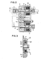
- Fig. 2 is a sectional view of the gear box of Fig. 1;
- Fig. 3 is a sectional view taken along line III - III of Fig. 1 in a magnified scale;
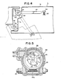
- Fig. 4 is a sectional view taken along line IV - IV of Fig. 1 in a magnified scale;
- Fig. 5 is a sectional front view of the speed reduction unit of the auxiliary door closure unit of Fig. 1;
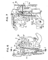
- Fig. 6 is a side view of the door lock of Fig. 1, as seen from the left side, in a magnified scale;
- Fig. 7 is a sectional view taken along line VII - VII of Fig. 6;
- Fig. 8 is an exploded view of the part around the shaft of the latch of Fig. 6;
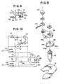
- Fig. 9 is a sectional view taken along line IX - IX of Fig. 1; and
- Fig. 10 is a circuit diagram showing an embodiment of the electric system of the device according to this invention.
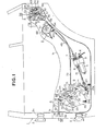
- As shown in Fig. 1 the device for opening and closing a door according to the present invention is comprised of a door opening and closing unit A and an auxiliary door closure unit B which are disposed within a rear door 1 of an automobile.
- The door opening and closing unit A is for opening and closing the door from the side of a
door hinge 2 while the auxiliary door closure unit B is for closing the door into a fully latched state from the side of adoor lock 3 provided on a free end of the door 1 upon closure of the door 1 to its half latched state. - Next, each of these units is described in detail in the following.
- Numeral 4 denotes an electric motor which is secured to an inner panel la of the door 1 and serves as a common drive means for both the door opening and closing unit A and the auxiliary door closure unit B.
- As most plainly illustrated in Figs. 1 and 2, to an end of the
motor 4 is fixed agear box 5, from which afirst output shaft 6 for driving the door opening and closing unit A, asecond output shaft 7 for driving the auxiliary door closure unit B and athird output shaft 8 for other purposes project. - The
first output shaft 6 is always drivingly connected to a rotary shaft 4a of themotor 4 by way of afirst gear 9 fixed to the rotary shaft.4a of themotor 4, andidle gear 10 meshed with thefirst gear 9 and a second gear 11 which is mounted on theidle gear 10 and, at the same time, engaged with thefirst output shaft 6 for integral motion therewith. - The
second output shaft 7 is connected to the rotary shaft 4a by way of thefirst gear 9, theidle gear 10 and the second gear 11 common to thefirst output shaft 6, and additionally anelectromagnetic clutch 12 which can connect and disconnect the connection between the rotary shaft 4a and thesecond output shaft 7 by its magnetization and demagnetization, respectively. - This
electromagnetic clutch 12 is comprised of amovable disc 13 which is rotatably fitted onto thesecond output shaft 7 and can slide axially relative to the second gear 11 but can not rotate relative to same, arotary disc 14 which is fixed to the second output shaft 7.opposite to themovable disc 13 and asolenoid 15 which is fixed around thesecond output shaft 7 within thegear box 5, and, only when this solenoid is energized, themovable disc 13 and therotary disc 14 are magnetized and the second gear 11 and thesecond output shaft 7 are drivingly connected to one another. - The
third output shaft 8 is connected to the rotary shaft 4a by way of thefirst gear 9, athird gear 16 meshing with thefirst gear 9 and anelectromagnetic clutch 17 of a similar construction as the previously mentionedelectromagnetic clutch 12. Thethird output shaft 8 is for driving a device other than those belonging to the present invention, such as a locking and unlocking knob, and its further description is omitted here as it is not directly related to the present invention. - The
first output shaft 6 is connected to aworm gear shaft 20 in aspeed reduction unit 19 having a clutch by way of aconnection cable 18 which is flexible and slightly twistable. - As plainly shown in Figs. 1 and 3, the
speed reduction unit 19 is comprised, in addition to theworm gear shaft 20 having aworm gear 20a, of aworm gear wheel 21 meshed with theworm gear 20a, anoutput shaft 22 rotatably penetrating through the center of theworm gear wheel 21, anoutput gear 23 fixed to an end of theoutput shaft 22 projecting from thespeed reduction unit 19 and anelectromagnetic clutch 24 for connecting and disconnecting the connection between theworm gear wheel 21 and theoutput shaft 22. - The
electromagnetic clutch 24 is comprised of a rotary disc 25 which is integrally fixed to theworm gear wheel 21, amovable disc 26 which is fixed to the-rotary shaft 22 at its center, opposite to the rotary disc 25, and, a fixedsolenoid 27 surrounding theoutput shaft 22, and, when thissolenoid 27 is energized, both the rotary disc 25 and themoveable disc 26 are magnetized and the worm .gear wheel 21 and theoutput shaft 22 become mutually engaged. - When the energization of the
solenoid 27 is terminated, the rotary disc 25 and themoveable disc 26 become mutually disengaged and theworm gear wheel 21 and theoutput shaft 22 become disconnected. The gap between the rotary disc 25 and themoveable disc 26 at this moment may be invisibly small and, in this embodiment, this gap is formed by the axial play of theoutput shaft 22. On the other hand,- it is also possible to make this gap much greater and employ a spring not shown in the drawings in an appropriate place to bias themoveable disc 26 away from the rotary disc 25. - Numeral 28 denotes a sector gear which is pivoted on the inner panel la with a substantially horizontally extending
shaft 29 and it lower fringe have a series of teeth 28a in an arcuate disposition for meshing with theoutput gear 23 of thespeed reduction unit 19. - To the upper rear fringe of the
sector gear 28 is pivotally mounted apiece 31 protruding toward the automobile cabin by means of ashaft 30 extending substantially vertically. Thispiece 31 is wrapped around the lower end of theshaft 30 and is biased by acoil spring 32 which is engaged with thepiece 31 at its one end and with thesector gear 28 at its other end in such a manner that the piece normally protrudes toward the cabin but its free end may be rotated forwardly when necessary (Refer to Fig. 9). - At the upper forward end of the
sector gear 28 is fixed apin 33 protruding toward the cabin. - The lower end of a vertically extending
arm 34 is pivoted on theshaft 29 closer to the cabin than thesector gear 28. The intermediate portion of thisarm 34 is rotatable to a certain extent between thepiece 31 and thepin 33 and is normally in contact with thepin 33 under the biasing force of thecoil spring 35. Thecoil spring 35 is wound around theshaft 29 and is engaged with the rear end of thearm 34 at its one end and with the front end of thesector gear 28 at its other end so as to bias thesector gear 28 always clockwise in the sense of Fig. 1. - As shown in Figs. 1 and 4, the rear end of a
push rod 37 extending horizontally along the fore and aft direction of the automobile is pivoted to the upper end of thearm 34 with ashaft 36 extending substantially perpendicularly to the door. - The intermediate portion of the
push rod 37 penetrates through awindow hole 38 provided in the front end plate lb of the door 1 and the front end of thepush rod 37 is pivoted to abracket 40 fixed to thecenter pillar 39 of the automobile body slightly outside of the pivot shaft 2a of thedoor hinge 2 by means of a vertically extendingshaft 41. - The door opening and closing unit A is thus formed from a series of the component parts, i.e., the
motor 4, thefirst output shaft 6 of thegear box 5, theconnection cable 18, thespeed reduction unit 19, thesector gear 28, thearm 34 and thepush rod 37. - With this door opening and closing unit A, the door may be opened, with the
electromagnetic clutch 24 of thespeed reduction unit 19 magnetized-, by rotating the output shaft 4a of themotor 4 in the predetermined normal direction thereby rotating thesector gear 28 counter-clockwise in Fig. 1, rotating thearm 34 with the protrudingpiece 31 counter-clockwise, and pushing thepush rod 37 forwardly relative to the door 1. - Also, by rotating the rotary shaft 4a of the motor Ln the reverse direction with the
electromagnetic clutch 24 magnetized, it is possible to rotate thesector gear 28 clockwise in the sense of Fig .1, rotate thearm 34 also clockwise by means of apin 33 and pull thepush rod 37 into the door 1 with the result that the ioor 1 is closed. - Numeral 42 denotes a limit switch for detecting the completely open :. state of the door 1 and is, in this embodiment, fixed to the inner panel 1a so that it may be activated by coming into contact with an appropriate part of the
arm 34 when thearm 34 has reached the position corresponding to the completely opened state of the door 1. - Throughout these steps of opening and closing the door by the door opening and closing unit A, no unduly great force nor great speed is required. This is so because the door opening and closing unit A does not need to forcibly close the door 1 to effect the engagement of a latch with a striker as has been the case with similar: conventional door control devices.
- Next, the auxiliary door closure unit B is described in detail in the following.
- This auxilairy door closure unit B is comprised of a series of elements, as will be described hereinafter, including the
motor 4, thesecond output shaft 7 and thedoor lock 3. - The
second output shaft 7 is connected to aworm gear shaft 45 of aspeed reduction unit 44 having a switch device shown in Figs. 1 and 5 by way of a connectingcable 43 similar to the previously mentioned connectingcable 18. - In addition-to the
worm gear shaft 45 having a worm gear 45a, thespeed reduction unit 44 is comprised of aworm gear wheel 46 meshing-with the worm gear 45a, anoutput shaft 47 fixed to the central part of theworm gear wheel 46 and protruding from one of the broad sides of thespeed reduction unit 44 and aswitch device 48. - The
switch device 48 is comprised of acircular base plate 49, a substantiallycircular conductor plate 50 fixed to the central part of the outer end surface of thebase plate 49 and provided with anotch 50a shaped as a sector, anotherconductor plate 51 shaped as a sector and arranged in such a manner as to fit into thenotch 50a with a certain gap therebetween, and a pair ofbrushes brushes conductor plate 51 over a certain range of the angle of thebase plate 49 and, otherwise, only thebrush 52 closer to theoutput shaft 47 is in..'contact with theconductor plate 5. More detailed description of the electrical connections of these members will be given later. - To the protruding end of the
output shaft 47 pro- truding sideways from thespeed reduction unit 44 is fixed a crank arm 54 and an end of a connectingrod 55 is pivoted to the free end of this crank arm 54. The relative positions of the crank arm 54 and theconductor plates conductor plate 51 comes in contact with both thebrushes - The other end of the connecting rod .55 is pivoted to the lower end of a bell crank 58 pivoted to a
base plate 57 of a door lockmain body 56. - As shown in Figs. 6 to 8, the
door lock 3 is designed to hold the door 1 in the closed state by means of the engagement between a striker 60 fixed to a siderear frame 59 of the automobile body and alatch 61 of the door lockmain body 56 mounted on the door 1 and is in most part built same as conventional known ones. Therefore, in the following description, only where it differs from such conventional ones is described in detail. - To the free end the rearward. arm of the bell crank 58 is pivoted the lower end of a
vertical arm 62. - The upper end of the connecting
rod 62 is pivoted, with apin 65, to the free end of arotary lever 64 which is in turn pivoted to theshaft 63 of thelatch 61 at its base end. On the outer periphery of the base end of thisrotary lever 64 is formed a protruding piece 64a protruding-rearwardly. -
Numeral 66 denotes a cam which is fitted onto theshaft 63 so as not to be relatively rotatable and is made to be integrally rotatable with thelatch 61 by way of theshaft 63. The outer periphery of thiscam 66 is comprised of a firstarcuate cam surface 66a protruding slightly from the general contour of the periphery, a secondarcuate cam surface 66b protruding further out than thefirst cam surface 66a and ashoulder 66c connecting from thesecond cam surface 66b. - The
shoulder 66c engages with the protruding piece 64a of therotary lever 64 only when therotary lever 64 has rotated counter-clockwise in Fig. 6 and, according to the rotation of therotary lever 64, rotates thelatch 61 from a half-latch position in which the latch is barely engaged with the striker 60 and the full-latched position in which the latch is completely engaged with the striker 60 and holds the door in the completely closed state by engaging with a pawl which is not shown in the drawings. - The
first cam surface 66a is positioned in such a manner that thelatch 61 comes into contact with alimit switch 67 fixed to thebase plate 57 of the door lockmain body 56 to activate it when the door 1 has closed to the half-latch position in which the striker-60 is barely engaged with thelatch 61 and thelatch 61 has been rotated slightly counter-clockwise from the door open position, such as the one shown in Fig. 6, due to slight impact on the latch.61 upon its collision with the striker 60. - The
second cam surface 66b is positioned in such a manner that thelatch 61 comes into contact with alimit switch 68 fixed to thebase plate 57 to activate it when thelatch 61 has reached an intermediate position between the half-latch position and the full-latch position. - The auxiliary door closure unit B can close the door 1 completely when the rotary shaft 4a of the
motor 4 is rotated in the reverse (or normal) direction to rotate the crank arm 54 one revolution along with the electromagnetic clutch 12 in thegear box 5, rotating therotary lever 64 counter-clockwise in Fig. 6 during the first half revolution of the crank arm 54, thereby rotating thelatch 61 at the half-latch position actively into the full-latch position. - As the crank arm 54 undergoes the latter half of the one revolution, the
rotary lever 64 rotates back clockwise to return to the position shown in Fig. 6. During this rotating-back motion of therotary lever 64, theshoulder 66c merely moves away from the protruding piece 64a and does not follow the motions of thecam 66 and thelatch 61, leaving thelatch 61 in engagement with the pawl which is not shown in the drawings. - The device according to this invention further has the following structure.
- As clearly shown in Figs. 1 and 9, a
base plate 69 is fixed to the inner panel la in the vicinity of thesector gear 28 within the door opening and closing unit A and arelease lever 71 is pivoted to thisbase plate 69 with ashaft 70. - The
release lever 71 is provided with an arm 7la which is engageable with the upper end of the protrudingpiece 31 pivoted to thesector gear 28 and normally remains stationary in the position shown in Fig 1 with its lower end in engagement with thestopper 69a under the spring force of acoil spring 72. - The
coil spring 72 wound around theshaft 70 is engaged with thestopper 69a at its one end and with the lower front end of therelease lever 71 at its other end, biasing therelease lever 71 counter-clockwise in Fig. 1. - To the lower end of the
release lever 71 is fixed an end of a flexibleinner cable 74, such as a wire, penetrating through a flexibleouter case 73. - The other end of the
inner cable 74 is fixed to the free end of arelease lever 75 in the door lockmain body 56 and connects therelease lever 71 with therelease lever 75. - An end of the
outer case 73 is fixed to the inner panel la in the vicinity of the lower end of therelease lever 71 while the other end of the outer case is fixed to the inner panel la in the vicinity of the free end of therelease lever 75, to guide theinner cable 74 therethrough. - The
release lever 75 has the same function as-the one employed in conventional door locks and can release the engagement between thelatch 61 and the striker 60 by rotating in an appropriate direction under the tension from the inner cable and removing the pawl, which is not shown in the drawings but catches thelatch 61 in the full-latch position, away from thelatch 61. - According to such a structure, the
door lock 3 may be released, as the door is to be opened from the closed state by the door opening and closing unit A and thesector gear 28 is about to be rotated counter-clockwise in Fig. 1, with thearm 71a of therelease lever 71 pushed upwards by the protrudingpiece 31 to rotate therelease lever 71 clockwise and therelease lever 75 rotated in the lock releasing direction pulled by theinner cable 74. - When the
sector gear 28 is to rotate back to the state shown in Fig. 1 during a door closure operation, the protrudingpiece 31 comes into contact with the upper end of thearm 71 a.. but is forced to rotate counter-clockwise in Fig..9 about theshaft 30 and goes over thearm 71a. Thus, the inconvenience that the protrudingpiece 31 is caught by thearm 71a and seized stationary before the full stop of thesector gear 28 does not develop. - For the purpose of assuring the returning motion of the
release lever 75, acompression coil spring 76 may be wound around theinner cable 74 between therelease lever 75 and the other end of theouter case 73, as shown in Fig. 1. - Fig. 10 shows the electric connections of the present embodiment of the invention.
-
Numerals 77 to 81 denote main switches that are incorporated in a single switch device so that they may be switched over between a door open side and a door close side, in synchronization. - Other elements in this drawing corresponding to those in other drawings are denoted by the same numerals.
- Next, the manner of the operation of the device according to this invention is described in the following making reference to Fig. 10.
- As shown in Fig. 10, simply switching over the mains switches 77 to 81 to the door open side causes the door 1 to open.
- Specifically, as the
switch 81 is closed theelectromagnetic clutch 24 becomes magnetized due to the electric current flowing therethrough by virtue of a closed circuit formed through a positive power source (+), themain switch 78, the limit switch 42 (which is closed), electromagnetic clutch 24, theswitch 81, themain switch 77, and a negative power source (-). - Meanwhile, the
limit switch 67 is in the activated state as the door 1 is located in a position between the half-latch position and the full-latch position and is switched over to the side of the electromagnetic clutch 12 which is demagnetized since themain switch 80 is open. - And the
motor 4 becomes energized as electric current flows through the path connecting the positive power source (+), themain switch 78, thelimit switch 42, themotor 4, themain switch 77 and the negative power source- (-). - Thus the
electromagnetic clutch 24 is magnetized and themotor 4 is energized to activate the door opening and closing unit A. - In an early phase of this action of the door opening and closing unit A, the
release lever 71 is rotated by the protrudingpiece 31 of thesector gear 28 to release thedoor lock 3 and the subsequent rotation of thesector gear 28 causes thepush rod 37 to be pushed out by way of thearm 34 , to open the door 1. - When the door 1 has completely opened, the
limit switch 42 is activated into the open state thereby demagnetizing theelectromagnetic clutch 24 and stopping themotor 4 with the result that the door 1 remains open. - Closing the door 1 may be simply effected by switching over the
main switches 77 to 81 to the door close side. - This causes both the
main switches 79 and 80-to be closed and themain switch 81 to open. - And the
limit switch 67 is switched over to the electromagnetic clutch 24 side when the door 1 has opened beyond the half-latch position. - Accordingly, the
electromagnetic clutch 24 is magnetized with the electric current flowing therethrough by virtue of the closed circuit formed along the line connecting the positive power source (+), themain switch 78, themain switch 79,'thelimit switch 67, the electromagnetic clutch 24, the limit switch 68 (which is closed), themain switch 77 and the negative power source (-), and themotor 4 rotates in the reverse direction with the polarity of the connections of the terminals of the motor being reversed relative to those in the above-described door opening operation. - This causes the door opening and closing unit A to rotate the door 1 in the closing direction.
- - When the door 1 has thus reached the half-latch position, the
limit switch 67 is activated and switched over to the side of the electromagnetic clutch 12, thereby demagnetizing theelectromagnetic clutch 12. - This causes the door opening and closing unit A to cease its action and the auxiliary door closure unit B to begin its action. Specifically, the crank arm 54 begins moving, rotating the
latch 61 to the full-latch position. - At the same time, the
base plate 49 of theswitch device 48 begins rotating causing thebrush 52 to come into contact with theconductor plate 50 and thebrush 53 to move away from theconductor plate 51, rendering it contactless. - When the door 1 has reached an intermediate position between the half-latch position and the full-latch position, the
limit switch 68 is activated and switched over to the side of theswitch device 48. - As a result, the circuit which has been formed from the
limit switch 68 to the negative power source (-) by way of themain switch 77 is switched over to extend through thelimit switch 68, thebrush 52, theconductor plate 50, themain switch 77 and the negative power source (-). However, the mechanical action of the auxiliary door closure unit B is still continued as it has been, and gradually pulls up thelatch 61 into the full-latch position. - After the
latch 61 has reached the full-latch position and the crank arm 54 and thebase plate 49 have returned to their original positions, thebrush 52 moves away from theconductor plate 50, opening the circuit to the negative power source (-), and soon thereafter, both thebrushes conductor plate 51, thereby stopping themotor 4. - At this moment, the supply of electric power to both the
electromagnetic clutch 12 and themotor 4 is already terminated and the circuits have restored to the door close state which preceded the overall door opening operation. - As may be clearly seen from the above description, the present invention provides both the door opening and closing unit A and the auxiliary door closure unit B , and this is meaningfull in assuring the complete closure of the door from the side of the door lock which is farthest away from the door hinge without requiring any unduly great force when the door is located in the range between the half-latch position or when the door is most difficult to be closed due to weather strip reaction force, lock resistance and so forth.
- Therefore, according to the present invention, it is not necessary any more to forcibly close a door, as has been customarily necessary when completely closing an automobile door of a conventional structure, thus reducing the magnitude of impact to the door and the automobile body and avoiding any deformation in the center pillar and the door by virtue of the elimination of any unduly great- force which may act on the center pillar and the door. Also, there is very little risk of injuring a passenger by catching part of his body between the door and the automobile body.
- Furthermore, no powerful motor is required and a compact and small-output motor is sufficient for the present invention, yet keeping the speed of opening and closing the door at an appropriate level.
- Although the automatic door opening and closing device according to this invention has been illustrated and described herein with respect to its specific embodiment, it will be understood that the invention is not regarded as being limited correspondingly in scope but includes all changes and modifications within the spirit of this invention..
- For instance, it .is possible to use another drive means, such as a solenoid, to release the door lock when the main switch is switched to the door open side, instead of the
release lever 71 and the protrudingpiece 31. - It is also possible to achieve complete closure of the door through the cooperation of the door opening and closing unit A and the auxiliary door closure unit B by activating the former while the latter is still in action.
- The drive means for both the door opening and closing unit A and the auxiliary door closure unit B was described as consisting of a common electric motor, but it is equally possible to use two separate electric motors instead of one.
Claims (7)
Applications Claiming Priority (2)
| Application Number | Priority Date | Filing Date | Title |
|---|---|---|---|
| JP56172152A JPS5876669A (en) | 1981-10-29 | 1981-10-29 | Automatic door opening and closing apparatus automobile |
| JP172152/81 | 1981-10-29 |
Publications (3)
| Publication Number | Publication Date |
|---|---|
| EP0078662A2 true EP0078662A2 (en) | 1983-05-11 |
| EP0078662A3 EP0078662A3 (en) | 1984-08-15 |
| EP0078662B1 EP0078662B1 (en) | 1987-05-20 |
Family
ID=15936523
Family Applications (1)
| Application Number | Title | Priority Date | Filing Date |
|---|---|---|---|
| EP82305711A Expired EP0078662B1 (en) | 1981-10-29 | 1982-10-27 | An automatic door opening and closing device |
Country Status (4)
| Country | Link |
|---|---|
| US (1) | US4530185A (en) |
| EP (1) | EP0078662B1 (en) |
| JP (1) | JPS5876669A (en) |
| DE (1) | DE3276382D1 (en) |
Cited By (6)
| Publication number | Priority date | Publication date | Assignee | Title |
|---|---|---|---|---|
| EP0310993A2 (en) * | 1987-10-08 | 1989-04-12 | Nissan Motor Co., Ltd. | Door control device |
| WO1990004526A1 (en) * | 1988-10-24 | 1990-05-03 | L'arte Srl | Electromechanical device with computerized control and method for performing and checking automatically the opening and closing of motor car doors |
| FR2716919A1 (en) * | 1994-03-04 | 1995-09-08 | Hobbycar Sa | Motor car door closing assembly |
| US6588828B2 (en) | 2000-04-25 | 2003-07-08 | Meritor Light Vehicle Systems (Uk) Limited | Vehicle aperture closure drive system |
| GB2427903A (en) * | 2004-05-10 | 2007-01-10 | Mitsui Mining & Smelting Co | Electromagnetic clutch comprising a cover member that is integrally formed with a transmission gear and a magnetic member |
| EP2733292A3 (en) * | 2012-11-20 | 2017-11-01 | Aisin Seiki Kabushiki Kaisha | Door actuating apparatus |
Families Citing this family (66)
| Publication number | Priority date | Publication date | Assignee | Title |
|---|---|---|---|---|
| US4617757A (en) * | 1984-11-02 | 1986-10-21 | Ohi Seisakusho Co., Ltd. | Sliding door opening-closing mechanism |
| US4644693A (en) * | 1985-08-20 | 1987-02-24 | Wang Hong J | Electric device for opening or shutting automative doors |
| US4842313A (en) * | 1987-11-12 | 1989-06-27 | Masco Industries, Inc. | Automatic vehicle striker powered by a unidirectional motor |
| AU600395B2 (en) * | 1987-09-25 | 1990-08-09 | Masco Industries, Inc. | Closing device |
| US4775178A (en) * | 1987-09-25 | 1988-10-04 | Maxaxam Corporation | Final closing device for closure member on a vehicle |
| JPH0247377U (en) * | 1988-09-27 | 1990-03-30 | ||
| US5004280A (en) * | 1989-03-03 | 1991-04-02 | Itt Corporation | Variable power drive for sliding door |
| JP2505445Y2 (en) * | 1990-02-23 | 1996-07-31 | 株式会社大井製作所 | Door lock half latch and full latch detection device |
| US5062241A (en) * | 1990-03-22 | 1991-11-05 | Masco Industries, Inc. | Varying radius helical cable spool for powered vehicle door systems |
| US4984385A (en) * | 1990-03-22 | 1991-01-15 | Masco Industries, Inc. | Powered closing assist mechanism for vehicle doors or lid members |
| US5025591A (en) * | 1990-03-22 | 1991-06-25 | Masco Industries, Inc. | Varying radius helical cable spool for powered vehicle door systems |
| US5140316A (en) * | 1990-03-22 | 1992-08-18 | Masco Industries, Inc. | Control apparatus for powered vehicle door systems |
| US5069000A (en) * | 1990-03-22 | 1991-12-03 | Masco Industries, Inc. | Reversing apparatus for powered vehicle door systems |
| US5239779A (en) * | 1990-03-22 | 1993-08-31 | Masco Industries, Inc. | Control apparatus for powered vehicle door systems |
| US5216838A (en) * | 1990-03-22 | 1993-06-08 | Masco Industries, Inc. | Control apparatus for powered vehicle door systems |
| US5189839A (en) * | 1990-03-22 | 1993-03-02 | Masco Industries, Inc. | Control apparatus for powered vehicle door systems |
| US5002331A (en) * | 1990-06-08 | 1991-03-26 | Prince Corporation | Pedal actuated vehicle door closer |
| DE4107272C2 (en) * | 1991-03-07 | 1996-04-18 | Bayerische Motoren Werke Ag | Motorized vehicle window |
| DE4107270C2 (en) * | 1991-03-07 | 1996-04-18 | Bayerische Motoren Werke Ag | Actuator for a vehicle opening window |
| JP2722895B2 (en) * | 1991-10-22 | 1998-03-09 | 日産自動車株式会社 | Automotive door opening and closing device |
| JP2768084B2 (en) * | 1991-10-22 | 1998-06-25 | 日産自動車株式会社 | Automotive door opening and closing device |
| JP3182294B2 (en) * | 1994-05-11 | 2001-07-03 | アスモ株式会社 | Moving object position detection device |
| US5906071A (en) * | 1995-07-12 | 1999-05-25 | Itt Automotive Electrical Systems, Inc. | Rear-center-mounted power door actuator |
| US5708338A (en) * | 1995-11-03 | 1998-01-13 | Ford Motor Company | System and method for controlling vehicle sliding door |
| US5644869A (en) * | 1995-12-20 | 1997-07-08 | Itt Automotive Electrical Systems, Inc. | Power drive for a movable closure with ball nut drive screw |
| US5787636A (en) * | 1995-12-20 | 1998-08-04 | Itt Automotive Electrical Systems, Inc. | Power drive for a movable closure with ball nut driven flexible cable |
| WO1997022771A1 (en) * | 1995-12-20 | 1997-06-26 | Itt Automotive Electrical Systems, Inc. | Power striker with inertially activated impact cycle |
| JP3007838B2 (en) * | 1996-03-01 | 2000-02-07 | アスモ株式会社 | Moving body position detecting device and vehicle door |
| US5755468A (en) * | 1996-05-03 | 1998-05-26 | Itt Automotive Electrical Systems, Inc. | Power striker with over-ride capabilities |
| DE19711563A1 (en) | 1997-03-20 | 1998-09-24 | Bosch Gmbh Robert | Circuit arrangement for controlling an electrically operated motor vehicle door lock or the like. |
| JP2001049924A (en) * | 1999-08-09 | 2001-02-20 | Aisin Seiki Co Ltd | Door closer device |
| JP2000160935A (en) * | 1998-11-30 | 2000-06-13 | Aisin Seiki Co Ltd | Door control device |
| ATE299619T1 (en) | 1998-12-03 | 2005-07-15 | Atoma Int Corp | AUXILIARY DRIVE WITH AN ELECTROMAGNETIC CLUTCH UNIT |
| US6848727B1 (en) | 1999-02-18 | 2005-02-01 | Atoma International Corp | Power door latch assembly |
| ATE301756T1 (en) * | 1999-02-18 | 2005-08-15 | Intier Automotive Closures Inc | POWER DRIVEN DOOR LOCKING DEVICE |
| US6276743B1 (en) * | 1999-06-29 | 2001-08-21 | Daimlerchrysler Corporation | Latching mechanism for a motor vehicle door |
| AU2481401A (en) | 1999-07-08 | 2001-02-05 | Aai Corporation | Passenger rail car sliding door with high platform threshold |
| DE10047946A1 (en) * | 1999-09-30 | 2001-04-19 | Siemens Automotive Corp Lp | Actuator for motor vehicle door lock has single motor driving window or door lock dependent on position of selector |
| EP1451429A1 (en) * | 2001-11-29 | 2004-09-01 | Intier Automotive Closures Inc. | Drive assembly for a power closure panel |
| US20040000823A1 (en) * | 2002-06-27 | 2004-01-01 | Gary Patridge | Actuator device |
| EP1530666A1 (en) * | 2002-08-23 | 2005-05-18 | DaimlerChrysler AG | Motor vehicle comprising a device for controlling the shifting movement of a closure element |
| US7325361B2 (en) * | 2003-03-19 | 2008-02-05 | Delphi Technologies, Inc. | Apparatus and method for providing a modular sliding door mechanism |
| US7243461B2 (en) * | 2003-03-19 | 2007-07-17 | Rogers Jr Lloyd W | Hinge mechanism for a sliding door |
| DE20307885U1 (en) * | 2003-05-21 | 2003-07-31 | Kiekert Ag | Combined drive unit for at least one unit and a door lock |
| DE10324323A1 (en) * | 2003-05-27 | 2004-12-16 | Valeo Sicherheitssysteme Gmbh | Drive for pushing the sliding door of a motor vehicle, comprises a core as power transmission member, with symmetrical rotation bodies arranged as engaging piece for form-locking engagement of drive wheel to the core |
| DE10324322A1 (en) * | 2003-05-27 | 2004-12-16 | Valeo Sicherheitssysteme Gmbh | Drive for automatic actuation of vehicle doors and vehicle flaps |
| US9523231B2 (en) | 2003-11-10 | 2016-12-20 | Strattec Power Access Llc | Attachment assembly and drive unit having same |
| US7422094B2 (en) * | 2003-11-28 | 2008-09-09 | Mitsu Mining & Smelting Co. Ltd. | Clutch mechanism for power device |
| JP2005206035A (en) * | 2004-01-22 | 2005-08-04 | Mitsuba Corp | Automatic open/close device for vehicle |
| DE202004006518U1 (en) * | 2004-04-24 | 2004-06-24 | Edscha Ag | Device for driving a motor vehicle door |
| KR100568115B1 (en) * | 2004-06-30 | 2006-04-05 | 삼성전자주식회사 | Incremental merge method and memory system using the same |
| DE102004061689A1 (en) * | 2004-12-22 | 2006-07-06 | Daimlerchrysler Ag | Vehicle door with exit help |
| EP1713160B1 (en) * | 2005-04-11 | 2020-06-17 | Delphi Technologies, Inc. | Drive device for motor operated vehicle door with movement sensor |
| DE102005061610A1 (en) * | 2005-12-21 | 2007-07-05 | Brose Fahrzeugteile Gmbh & Co. Kommanditgesellschaft, Coburg | Method and device for controlling the closing movement of a body component for vehicles |
| WO2009011275A1 (en) * | 2007-07-13 | 2009-01-22 | Toyota Boshoku Kabushiki Kaisha | Lock release mechanism |
| US8068959B2 (en) * | 2007-08-07 | 2011-11-29 | Ford Global Technologies, Llc | Vehicle door active and passive control device |
| DE102008064570A1 (en) * | 2008-12-19 | 2010-06-24 | Brose Fahrzeugteile Gmbh & Co. Kommanditgesellschaft, Coburg | Device and method for controlling the movement of a motorized and manually movable vehicle part |
| US10337216B2 (en) | 2014-01-02 | 2019-07-02 | Strattec Power Access Llc | Vehicle door |
| US10822844B2 (en) * | 2014-02-14 | 2020-11-03 | Inteva Products, Llc | Latch with linearly operated lock lever |
| JP5974026B2 (en) * | 2014-02-21 | 2016-08-23 | シロキ工業株式会社 | Opening and closing body drive control device |
| US10344519B2 (en) | 2017-04-11 | 2019-07-09 | Ford Global Technologies Llc | Vehicle power door system |
| CN109267859B (en) * | 2018-09-17 | 2020-09-04 | 杭州知桔科技有限公司 | Anti-mistaken-clamping new energy automobile door safety lock device |
| CN109306696A (en) * | 2018-10-23 | 2019-02-05 | 马鞍山宏泰建材股份有限公司 | Square pile structure |
| US11680430B2 (en) * | 2019-02-20 | 2023-06-20 | Brose Schließsysteme GmbH & Co. Kommanditgesellschaft, Wuppertal | Linear cinching spindle |
| DE102019218169A1 (en) * | 2019-11-25 | 2021-05-27 | Vitesco Technologies GmbH | Actuator for a side door of a motor vehicle |
| KR102363859B1 (en) * | 2020-04-21 | 2022-02-17 | 주식회사 우보테크 | E-Latch for Vehicle Door |
Citations (2)
| Publication number | Priority date | Publication date | Assignee | Title |
|---|---|---|---|---|
| GB1077146A (en) * | 1963-10-12 | 1967-07-26 | Isuzu Motors Ltd | Door opening and closing mechanism and a vehicle incorporating the same |
| US3343303A (en) * | 1965-07-27 | 1967-09-26 | Gen Motors Corp | Vehicle body deck lid operating system |
Family Cites Families (7)
| Publication number | Priority date | Publication date | Assignee | Title |
|---|---|---|---|---|
| US2833536A (en) * | 1956-11-13 | 1958-05-06 | Gen Motors Corp | Power operated rear compartment actuator and lock assembly |
| US2898138A (en) * | 1956-11-19 | 1959-08-04 | Jervis Corp | Power operated latch mechanism |
| US3344554A (en) * | 1964-10-05 | 1967-10-03 | Isuzu Motors Ltd | Door open-and-close mechanism |
| US3398484A (en) * | 1965-06-04 | 1968-08-27 | Katsumura Toru | Car door actuator |
| JPS458562Y1 (en) * | 1967-03-16 | 1970-04-22 | ||
| US3653154A (en) * | 1970-02-11 | 1972-04-04 | Power Car Door Corp | Door actuator |
| US3989287A (en) * | 1972-08-28 | 1976-11-02 | Keystone Industries, Inc. | Automotive vehicle door retarding and closing mechanism |
-
1981
- 1981-10-29 JP JP56172152A patent/JPS5876669A/en active Granted
-
1982
- 1982-10-27 US US06/436,968 patent/US4530185A/en not_active Expired - Lifetime
- 1982-10-27 EP EP82305711A patent/EP0078662B1/en not_active Expired
- 1982-10-27 DE DE8282305711T patent/DE3276382D1/en not_active Expired
Patent Citations (2)
| Publication number | Priority date | Publication date | Assignee | Title |
|---|---|---|---|---|
| GB1077146A (en) * | 1963-10-12 | 1967-07-26 | Isuzu Motors Ltd | Door opening and closing mechanism and a vehicle incorporating the same |
| US3343303A (en) * | 1965-07-27 | 1967-09-26 | Gen Motors Corp | Vehicle body deck lid operating system |
Cited By (10)
| Publication number | Priority date | Publication date | Assignee | Title |
|---|---|---|---|---|
| EP0310993A2 (en) * | 1987-10-08 | 1989-04-12 | Nissan Motor Co., Ltd. | Door control device |
| EP0310993A3 (en) * | 1987-10-08 | 1990-06-06 | Nissan Motor Co., Ltd. | Door control device |
| WO1990004526A1 (en) * | 1988-10-24 | 1990-05-03 | L'arte Srl | Electromechanical device with computerized control and method for performing and checking automatically the opening and closing of motor car doors |
| FR2716919A1 (en) * | 1994-03-04 | 1995-09-08 | Hobbycar Sa | Motor car door closing assembly |
| US6588828B2 (en) | 2000-04-25 | 2003-07-08 | Meritor Light Vehicle Systems (Uk) Limited | Vehicle aperture closure drive system |
| GB2427903A (en) * | 2004-05-10 | 2007-01-10 | Mitsui Mining & Smelting Co | Electromagnetic clutch comprising a cover member that is integrally formed with a transmission gear and a magnetic member |
| GB2427903B (en) * | 2004-05-10 | 2007-07-25 | Mitsui Mining & Smelting Co | Electromagnetic clutch comprising a cover member integrally formed with transmission gear and magnetic member |
| US7429073B2 (en) | 2004-05-10 | 2008-09-30 | Mitsui Mining & Smelting Co., Ltd. | Door operating apparatus, electromagnetic clutch, and coupling mechanism |
| US8007027B2 (en) | 2004-05-10 | 2011-08-30 | Mitsui Mining & Smelting Co., Ltd. | Door operating apparatus, electromagnetic clutch, and coupling mechanism |
| EP2733292A3 (en) * | 2012-11-20 | 2017-11-01 | Aisin Seiki Kabushiki Kaisha | Door actuating apparatus |
Also Published As
| Publication number | Publication date |
|---|---|
| US4530185A (en) | 1985-07-23 |
| JPS5876669A (en) | 1983-05-09 |
| EP0078662A3 (en) | 1984-08-15 |
| JPH0112912B2 (en) | 1989-03-02 |
| EP0078662B1 (en) | 1987-05-20 |
| DE3276382D1 (en) | 1987-06-25 |
Similar Documents
| Publication | Publication Date | Title |
|---|---|---|
| EP0078662A2 (en) | An automatic door opening and closing device | |
| US5155937A (en) | Automotive slide door operating system with half-latch and full-latch detecting device | |
| CA1228880A (en) | Electrically-opened latch, in particular for motor vehicle doors | |
| JPH0747586Y2 (en) | Automatic door closing device | |
| US4121382A (en) | Mechanized door operating means for a motor vehicle | |
| JP2855557B2 (en) | Door lock device for automobile | |
| EP0745746B1 (en) | Latch cinching mechanism and latch assembly | |
| US5564761A (en) | Door lock device with automatic closing mechanism | |
| US3343303A (en) | Vehicle body deck lid operating system | |
| JPH02231277A (en) | Control system of automobile | |
| JP3286243B2 (en) | Door locking and unlocking device | |
| JP2527802Y2 (en) | Automatic door opening device | |
| JP2583477B2 (en) | Automatic door closing device for automobiles | |
| JPH0235826B2 (en) | ||
| JPS58178779A (en) | Automatic door opening and closing apparatus in automobile | |
| JPS6228271B2 (en) | ||
| US20020027365A1 (en) | Electromagnetic vehicle closure panel cinching mechanism | |
| JP2803122B2 (en) | Door closing device | |
| JP2800013B2 (en) | Door closing device | |
| JP2588070B2 (en) | Automatic door closing device for automobiles | |
| JPH0747587Y2 (en) | Automatic door closing device | |
| JP2658273B2 (en) | Door closing device | |
| JPH0235827B2 (en) | ||
| JP2514489Y2 (en) | Vehicle door lock device | |
| JPH0513228B2 (en) |
Legal Events
| Date | Code | Title | Description |
|---|---|---|---|
| PUAI | Public reference made under article 153(3) epc to a published international application that has entered the european phase |
Free format text: ORIGINAL CODE: 0009012 |
|
| AK | Designated contracting states |
Designated state(s): DE FR GB |
|
| PUAL | Search report despatched |
Free format text: ORIGINAL CODE: 0009013 |
|
| AK | Designated contracting states |
Designated state(s): DE FR GB |
|
| 17P | Request for examination filed |
Effective date: 19841231 |
|
| RAP1 | Party data changed (applicant data changed or rights of an application transferred) |
Owner name: NISSAN MOTOR CO., LTD. Owner name: OHI SEISAKUSHO CO., LTD. |
|
| GRAA | (expected) grant |
Free format text: ORIGINAL CODE: 0009210 |
|
| AK | Designated contracting states |
Kind code of ref document: B1 Designated state(s): DE FR GB |
|
| ET | Fr: translation filed | ||
| REF | Corresponds to: |
Ref document number: 3276382 Country of ref document: DE Date of ref document: 19870625 |
|
| PLBE | No opposition filed within time limit |
Free format text: ORIGINAL CODE: 0009261 |
|
| STAA | Information on the status of an ep patent application or granted ep patent |
Free format text: STATUS: NO OPPOSITION FILED WITHIN TIME LIMIT |
|
| 26N | No opposition filed | ||
| PGFP | Annual fee paid to national office [announced via postgrant information from national office to epo] |
Ref country code: FR Payment date: 20011010 Year of fee payment: 20 |
|
| PGFP | Annual fee paid to national office [announced via postgrant information from national office to epo] |
Ref country code: GB Payment date: 20011031 Year of fee payment: 20 |
|
| PGFP | Annual fee paid to national office [announced via postgrant information from national office to epo] |
Ref country code: DE Payment date: 20011112 Year of fee payment: 20 |
|
| REG | Reference to a national code |
Ref country code: GB Ref legal event code: IF02 |
|
| PG25 | Lapsed in a contracting state [announced via postgrant information from national office to epo] |
Ref country code: GB Free format text: LAPSE BECAUSE OF EXPIRATION OF PROTECTION Effective date: 20021026 |
|
| REG | Reference to a national code |
Ref country code: GB Ref legal event code: PE20 Effective date: 20021026 |