EP0080772A1 - Jack and plug electrical assembly - Google Patents
Jack and plug electrical assembly Download PDFInfo
- Publication number
- EP0080772A1 EP0080772A1 EP82201497A EP82201497A EP0080772A1 EP 0080772 A1 EP0080772 A1 EP 0080772A1 EP 82201497 A EP82201497 A EP 82201497A EP 82201497 A EP82201497 A EP 82201497A EP 0080772 A1 EP0080772 A1 EP 0080772A1
- Authority
- EP
- European Patent Office
- Prior art keywords
- jack
- plug
- cavity
- housing
- insert
- Prior art date
- Legal status (The legal status is an assumption and is not a legal conclusion. Google has not performed a legal analysis and makes no representation as to the accuracy of the status listed.)
- Granted
Links
Images


Classifications
-
- H—ELECTRICITY
- H01—ELECTRIC ELEMENTS
- H01R—ELECTRICALLY-CONDUCTIVE CONNECTIONS; STRUCTURAL ASSOCIATIONS OF A PLURALITY OF MUTUALLY-INSULATED ELECTRICAL CONNECTING ELEMENTS; COUPLING DEVICES; CURRENT COLLECTORS
- H01R24/00—Two-part coupling devices, or either of their cooperating parts, characterised by their overall structure
- H01R24/60—Contacts spaced along planar side wall transverse to longitudinal axis of engagement
- H01R24/62—Sliding engagements with one side only, e.g. modular jack coupling devices
-
- H—ELECTRICITY
- H01—ELECTRIC ELEMENTS
- H01R—ELECTRICALLY-CONDUCTIVE CONNECTIONS; STRUCTURAL ASSOCIATIONS OF A PLURALITY OF MUTUALLY-INSULATED ELECTRICAL CONNECTING ELEMENTS; COUPLING DEVICES; CURRENT COLLECTORS
- H01R13/00—Details of coupling devices of the kinds covered by groups H01R12/70 or H01R24/00 - H01R33/00
- H01R13/02—Contact members
- H01R13/26—Pin or blade contacts for sliding co-operation on one side only
-
- H—ELECTRICITY
- H01—ELECTRIC ELEMENTS
- H01R—ELECTRICALLY-CONDUCTIVE CONNECTIONS; STRUCTURAL ASSOCIATIONS OF A PLURALITY OF MUTUALLY-INSULATED ELECTRICAL CONNECTING ELEMENTS; COUPLING DEVICES; CURRENT COLLECTORS
- H01R13/00—Details of coupling devices of the kinds covered by groups H01R12/70 or H01R24/00 - H01R33/00
- H01R13/46—Bases; Cases
- H01R13/502—Bases; Cases composed of different pieces
- H01R13/506—Bases; Cases composed of different pieces assembled by snap action of the parts
-
- H—ELECTRICITY
- H01—ELECTRIC ELEMENTS
- H01R—ELECTRICALLY-CONDUCTIVE CONNECTIONS; STRUCTURAL ASSOCIATIONS OF A PLURALITY OF MUTUALLY-INSULATED ELECTRICAL CONNECTING ELEMENTS; COUPLING DEVICES; CURRENT COLLECTORS
- H01R31/00—Coupling parts supported only by co-operation with counterpart
Abstract
Description
- This invention relates to electrical assemblies. More specifically, it refers to an electrical assembly employing a jack and plug with electrical contact positions on two sides of the plug mating with two sets of electrical conductors in the jack.
- Jacks and plugs have found widespread acceptance in the telecommunications systems of the world because of their ease in connecting and disconnecting, low cost and reliable electrical connections. U.S. Patent 3,850,497 describes the jacks in detail and U.S. Patent 3,860,316 does likewise with the plugs. One of the limitations of the assembly of these jacks and plugs is that they have a limited number of electrical contact positions. Conventional jacks currently available commercially have up to twelve positions. Since these jacks and plugs are also useful in other electronic systems which require more positions, a need has now arisen for greatly increased electrical positions for each jack/plug assembly. The known jacks and plugs cannot satisfy the demand for more than twelve electrical contact positions.
- I have solved the problem discussed above with a jack and plug assembly that more than doubles the positions available in known jacks and plugs.
- My assembly employs a jack having three internal cavities. The central cavity extends from the front to the back of the jack housing and accommodates a complementary plug. The plug rides in a pair of guiderails located in each sidewall of the jack housing. On each side of the central cavity there is also an upper cavity and lower cavity respectively, each one defined by sidewalls, a front wall and a ceiling or floor, respectively, accommodating a pair of inserts.
- The plug has a cord input end, an internal cavity within the plug housing enclosing multiple insulated wires from the cord, means for securing the cord within the plug housing and a conductor contact end opposite the cord-input end. The contact end has an upper and lower end, each containing multiple conductor receiving troughs formed within a portion of the cavity. Each trough accommodates one of the insulated wires. The plug also has a plurality of terminal receiving openings, each one communicating with a trough and the exterior of the plug. A conductive insulation piercing terminal is positioned within each terminal receiving opening with its first contact position engaging the conductive wire by piercing the insulation of the insulated wire in the trough and a second contact position facing the exterior of the plug and being available to electrically contact a spring wire conductor from a jack insert.
- Each insert contains multiple channels, each channel retaining a single spring wire conductor. The ends of these conductors exit from one end of the insert and are bent back over the top of the insert so that the ends are available for electrical contact with a contact position on the plug.
- The present invention may be best understood by those of ordinary skill in the art by reference to the following detailed description when considered in conjunction with the accompanying drawings in which:
- FIG. 1 is an exploded view of the electrical assembly parts showing the inserts, jack and plug before assembly. One insert shown in phantom outside the jack is also shown in a cut-away inserted within the jack. Conversely the other insert shown in phantom within the jack is also shown in its position prior to insertion into the jack.
- FIG. 2 is a perspective of the back portion of the jack with the two inserts in place. The plug is shown in perspective about to be inserted into the jack.
- FIG. 3 is a perspective and partial cut-away of the jack front portion with the plug partially inserted.
- FIG. 4 is a perspective of the plug latched to the front portion of the jack.
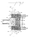
- FIG. 5 is a cross section of the plug and jack assembled as shown in FIG. 4.
- Referring now to the drawings in which like reference characters designate like or corresponding parts throughout the several views, there is shown in Figure 1 the multiconnection electrical assembly. The
jack 10 has adielectric housing 18 with a front portion 20.and arear portion 22.Mounting ears dielectric housing 18 formed in the molding process. - The
housing 18 has acentral cavity 34, anupper cavity 36 and alower cavity 38. - The
central cavity 34 is defined bysidewalls 40 and 42. Each sidewall hasidentical guiderails plug 12 when inserted into thejack 10. Thesidewalls 40 and 42 each have alatch receptacle Sidewalls 40 and 42 also containlatch receptacles latches 64 on theinserts - The
front portion 20 of thedielectric housing 18 contains apartial front wall 52 and 54, to retain theupper insert 16 and thelower insert 14, respectively. - The
plug 12 contains adielectric housing 78 withexterior latches 66. Acord input end 68 in thehousing 78 receives acord 70. The cord contains multiple insulatedwires 86 as shown in Figure 5. The plug also has astrain relief 72 which is obtained by deforming the plastic of thedielectric housing 78. The inside of the plug consists of acavity 106 within which the insulated wires are positioned. Approximately half thewires 86 lead to the upper portion of theplug 12 and the other half to the lower portion. Adivider 94 separates theconductive wires 86. Thecontact end 80 has an upper and lower end, each containing multipleconductor receiving troughs 76 which form a portion of thecavity 34 within the plug. Eachtrough 76 will contain one of the insulatedwires 86. A plurality of terminal receiving openings 82 communicates with the trough. A conductiveinsulation piercing terminal 74 is positioned within each terminal receiving opening 82 with itsfirst contact portion 84 engaging theconductive wire 86 in thetrough 76 and asecond contact portion 88 facing the exterior of the plug and being available to electrically contact thespring wire conductor 90 in both theupper insert 16 and thelower insert 14. - The
plug 12 is inserted into thefront 20 of thejack 10 so that thelatches 66 move within thelatch receptacles rails plug 12 fills thecavity 34 of thejack 10. Theplug 12 can be removed from thejack 10 by pushing the ends of thelatches 66 inwards, thus disengaging it from thelatch receptacle ledges second contact end 88 of theterminal 74 is exposed on both sides of theplug 12 to readily engage theconductive wires 90 from the upper andlower inserts - The
inserts latches 64 on each side that ride inlatch grooves jack 10. Each insert contains internal channels within its innerplastic body 102. An insulatedwire 92 is stripped to expose itsend 104 which is inserted into a channel within the insert and is crimped 96 to aconductive wire 90. The conductive wire is bent back over itself outside the insert body. Thelower insert 14 is inserted into thelower cavity 38 of thejack 10 and thetop insert 16 is inserted into theupper cavity 36 in thejack 10. Each insert is located within thejack 10 so that itsconductive wires 90 are free within thecavity 34 ofjack 10. After the inserts have been placed within the jack housing, the movement of theplug 12 intocavity 34 ofjack housing 10 causes theconductive wires 90 to contact the terminal surfaces 88 and make an electrical connection with theplug 12. - Molding holes 98 in the
jack housing 18 facilitates the making of internal cavities. - The
conductive wires 90 are plated with gold or some other material resistant to oxidation. The wire itself can be copper or other conductive material. The jack housing, plug housing and insert housings can all be made of filled polyester or other dielectric plastic material. - This assembly can be used in the telecommunications industry for telephones or for contacts in computers, toys and other devices employing electrical connections.
Claims (4)
Priority Applications (1)
| Application Number | Priority Date | Filing Date | Title |
|---|---|---|---|
| AT82201497T ATE30284T1 (en) | 1981-11-25 | 1982-11-24 | ELECTRICAL ASSEMBLY OF A PLUG AND SOCKET. |
Applications Claiming Priority (2)
| Application Number | Priority Date | Filing Date | Title |
|---|---|---|---|
| US325024 | 1981-11-25 | ||
| US06/325,024 US4406509A (en) | 1981-11-25 | 1981-11-25 | Jack and plug electrical assembly |
Publications (2)
| Publication Number | Publication Date |
|---|---|
| EP0080772A1 true EP0080772A1 (en) | 1983-06-08 |
| EP0080772B1 EP0080772B1 (en) | 1987-10-14 |
Family
ID=23266119
Family Applications (1)
| Application Number | Title | Priority Date | Filing Date |
|---|---|---|---|
| EP82201497A Expired EP0080772B1 (en) | 1981-11-25 | 1982-11-24 | Jack and plug electrical assembly |
Country Status (10)
| Country | Link |
|---|---|
| US (1) | US4406509A (en) |
| EP (1) | EP0080772B1 (en) |
| JP (1) | JPS5897277A (en) |
| KR (1) | KR890004498B1 (en) |
| AT (1) | ATE30284T1 (en) |
| BR (1) | BR8206736A (en) |
| CA (1) | CA1173533A (en) |
| DE (1) | DE3277486D1 (en) |
| HK (1) | HK87588A (en) |
| MX (1) | MX152831A (en) |
Cited By (10)
| Publication number | Priority date | Publication date | Assignee | Title |
|---|---|---|---|---|
| EP0175868A2 (en) * | 1984-09-28 | 1986-04-02 | STEWART STAMPING CORPORATION (a Delaware Corporation) | Jack and connector |
| GB2242080A (en) * | 1990-03-09 | 1991-09-18 | Krone Aktiengesellscaft | Electrical connectors |
| EP0527332A2 (en) * | 1991-08-09 | 1993-02-17 | Quante Aktiengesellschaft | Jack with resilient one-piece guide means |
| FR2694456A1 (en) * | 1992-07-31 | 1994-02-04 | Pouyet Int | "Modular jack" type female socket with integrated connectors. |
| US5503572A (en) * | 1994-05-17 | 1996-04-02 | Mod-Tap Corporation | Communications connectors |
| US5655934A (en) * | 1994-07-21 | 1997-08-12 | Krone Ag | Electrical plug connector |
| US6068520A (en) * | 1997-03-13 | 2000-05-30 | Berg Technology, Inc. | Low profile double deck connector with improved cross talk isolation |
| FR2798008A1 (en) * | 1999-08-31 | 2001-03-02 | Fci Automotive France | High transfer rate telephone jack connector manufacture method having blind holder base with T-bar shaped section protecting/guiding contact wires. |
| AU764903B2 (en) * | 1993-03-12 | 2003-09-04 | Cekan/Cdt A/S | A connector element for telecommunication |
| USRE41311E1 (en) | 1992-02-24 | 2010-05-04 | Commscope, Inc. Of North America | High frequency electrical connector |
Families Citing this family (36)
| Publication number | Priority date | Publication date | Assignee | Title |
|---|---|---|---|---|
| US4538874A (en) * | 1982-05-27 | 1985-09-03 | Molex Incorporated | Modular jack assembly |
| US4553800A (en) * | 1982-10-15 | 1985-11-19 | Virginia Patent Development Corp. | Low profile modular plug |
| US4477141A (en) * | 1982-11-19 | 1984-10-16 | At&T Technologies, Inc. | Tricoupler for modular wiring systems |
| US4778407A (en) * | 1982-12-23 | 1988-10-18 | Amp Incorporated | Electrical connector plug for conductors on closely spaced centers |
| US4458973A (en) * | 1983-01-28 | 1984-07-10 | Amp Incorporated | Connector assembly having improved internal latching system |
| JPS59221807A (en) * | 1983-05-31 | 1984-12-13 | Canon Inc | Fm modulating signal reproducing device |
| US4620762A (en) * | 1984-10-16 | 1986-11-04 | Amp Incorporated | Electronic key assemblies |
| US4602838A (en) * | 1984-10-16 | 1986-07-29 | Amp Incorporated | Electronic key assemblies |
| US4648665A (en) * | 1984-10-16 | 1987-03-10 | Amp Incorporated | Electronic key assemblies |
| US4572602A (en) * | 1984-10-31 | 1986-02-25 | Amp Incorporated | Electrical connector assembly with guide member |
| US4703989A (en) * | 1986-06-13 | 1987-11-03 | Cobe Laboratories, Inc. | Electrical connectors for a liquid sensor |
| US4859201A (en) * | 1986-12-22 | 1989-08-22 | Amp Incorporated | Data communications outlet |
| JPH0785429B2 (en) * | 1987-04-15 | 1995-09-13 | 松下電工株式会社 | Telephone module |
| US4806117A (en) * | 1987-08-21 | 1989-02-21 | Amp Incorporated | Modular plug coupler |
| US4817283A (en) * | 1987-08-21 | 1989-04-04 | Amp Incorporated | Method of forming a modular plug coupler |
| US4904209A (en) * | 1987-12-04 | 1990-02-27 | Amp Incorporated | Modular plug coupler |
| JPH0435370U (en) * | 1990-07-20 | 1992-03-24 | ||
| JPH0615276U (en) * | 1992-07-23 | 1994-02-25 | モレックス インコーポレーテッド | Electrical connector |
| US5672074A (en) * | 1995-06-22 | 1997-09-30 | Panduit Corp. | Connector mounting receptacles |
| US5639267A (en) * | 1996-01-26 | 1997-06-17 | Maxconn Incorporated | Modular jack assembly |
| US5911602A (en) * | 1996-07-23 | 1999-06-15 | Superior Modular Products Incorporated | Reduced cross talk electrical connector |
| US5674093A (en) * | 1996-07-23 | 1997-10-07 | Superior Modular Process Incorporated | Reduced cross talk electrical connector |
| JP3389119B2 (en) * | 1998-10-22 | 2003-03-24 | 日本電気株式会社 | Electronic components |
| HUP0105197A2 (en) * | 1999-01-15 | 2002-05-29 | Adc Telecommunications Inc | Telecommunications jack assembly |
| US6334792B1 (en) | 1999-01-15 | 2002-01-01 | Adc Telecommunications, Inc. | Connector including reduced crosstalk spring insert |
| US6520806B2 (en) | 1999-08-20 | 2003-02-18 | Adc Telecommunications, Inc. | Telecommunications connector for high frequency transmissions |
| US6089923A (en) | 1999-08-20 | 2000-07-18 | Adc Telecommunications, Inc. | Jack including crosstalk compensation for printed circuit board |
| US6168461B1 (en) * | 1999-12-20 | 2001-01-02 | Teckon Electronics Corp. | Module jack arrangement |
| US6554653B2 (en) | 2001-03-16 | 2003-04-29 | Adc Telecommunications, Inc. | Telecommunications connector with spring assembly and method for assembling |
| US6830486B2 (en) * | 2002-07-19 | 2004-12-14 | Adc Telecommunications, Inc. | Digital switching cross-connect module |
| US7070457B2 (en) * | 2002-07-19 | 2006-07-04 | Adc Telecommunications, Inc. | Telecommunications connector |
| US6814624B2 (en) * | 2002-11-22 | 2004-11-09 | Adc Telecommunications, Inc. | Telecommunications jack assembly |
| MXPA05010114A (en) * | 2003-03-21 | 2006-04-27 | Nexmed Holdings Inc | Antifungal nail coat and method of use. |
| US7086891B2 (en) * | 2003-04-21 | 2006-08-08 | Sheng-Hsin Liao | Electrical plug with protection structure |
| US7048550B2 (en) * | 2004-06-18 | 2006-05-23 | Hon Hai Precision Ind. Co., Ltd. | Electrical adapter assembly |
| DE102016115601A1 (en) * | 2016-08-23 | 2018-03-01 | Wago Verwaltungsgesellschaft Mbh | Spring terminal connection |
Citations (4)
| Publication number | Priority date | Publication date | Assignee | Title |
|---|---|---|---|---|
| US2894097A (en) * | 1956-09-17 | 1959-07-07 | Norman L Bassin | Electrical junction box and electrical fused plug connections |
| US3954320A (en) * | 1973-07-06 | 1976-05-04 | Western Electric Company, Inc. | Electrical connecting devices for terminating cords |
| US4191443A (en) * | 1977-07-28 | 1980-03-04 | Slater Electric Inc. | Electrical connector means |
| EP0028460A1 (en) * | 1979-10-16 | 1981-05-13 | AMP INCORPORATED (a New Jersey corporation) | A double-ended electrical plug receptacle connector assembly |
Family Cites Families (3)
| Publication number | Priority date | Publication date | Assignee | Title |
|---|---|---|---|---|
| US3850497A (en) * | 1972-03-08 | 1974-11-26 | Bell Telephone Labor Inc | Connector |
| US4193654A (en) * | 1978-09-08 | 1980-03-18 | Amp Incorporated | Electrical connector receptacles |
| US4367908A (en) * | 1980-06-05 | 1983-01-11 | Akzona Incorporated | Electrical connector coupling |
-
1981
- 1981-11-25 US US06/325,024 patent/US4406509A/en not_active Expired - Lifetime
-
1982
- 1982-11-22 BR BR8206736A patent/BR8206736A/en unknown
- 1982-11-23 CA CA000416179A patent/CA1173533A/en not_active Expired
- 1982-11-24 DE DE8282201497T patent/DE3277486D1/en not_active Expired
- 1982-11-24 AT AT82201497T patent/ATE30284T1/en not_active IP Right Cessation
- 1982-11-24 MX MX195327A patent/MX152831A/en unknown
- 1982-11-24 JP JP57204719A patent/JPS5897277A/en active Granted
- 1982-11-24 KR KR8205294A patent/KR890004498B1/en active
- 1982-11-24 EP EP82201497A patent/EP0080772B1/en not_active Expired
-
1988
- 1988-10-27 HK HK875/88A patent/HK87588A/en unknown
Patent Citations (4)
| Publication number | Priority date | Publication date | Assignee | Title |
|---|---|---|---|---|
| US2894097A (en) * | 1956-09-17 | 1959-07-07 | Norman L Bassin | Electrical junction box and electrical fused plug connections |
| US3954320A (en) * | 1973-07-06 | 1976-05-04 | Western Electric Company, Inc. | Electrical connecting devices for terminating cords |
| US4191443A (en) * | 1977-07-28 | 1980-03-04 | Slater Electric Inc. | Electrical connector means |
| EP0028460A1 (en) * | 1979-10-16 | 1981-05-13 | AMP INCORPORATED (a New Jersey corporation) | A double-ended electrical plug receptacle connector assembly |
Cited By (15)
| Publication number | Priority date | Publication date | Assignee | Title |
|---|---|---|---|---|
| EP0175868A3 (en) * | 1984-09-28 | 1989-01-25 | Stewart Stamping Corporation (A Delaware Corporation) | Jack and connector |
| EP0175868A2 (en) * | 1984-09-28 | 1986-04-02 | STEWART STAMPING CORPORATION (a Delaware Corporation) | Jack and connector |
| GB2242080B (en) * | 1990-03-09 | 1994-12-21 | Krone Ag | Electrical connectors |
| GB2242080A (en) * | 1990-03-09 | 1991-09-18 | Krone Aktiengesellscaft | Electrical connectors |
| EP0527332A2 (en) * | 1991-08-09 | 1993-02-17 | Quante Aktiengesellschaft | Jack with resilient one-piece guide means |
| EP0527332A3 (en) * | 1991-08-09 | 1993-06-09 | Quante Aktiengesellschaft | Jack with resilient one-piece guide means |
| USRE41311E1 (en) | 1992-02-24 | 2010-05-04 | Commscope, Inc. Of North America | High frequency electrical connector |
| EP0585179A1 (en) * | 1992-07-31 | 1994-03-02 | Pouyet International | Modular jack-type socket and integrated terminals |
| FR2694456A1 (en) * | 1992-07-31 | 1994-02-04 | Pouyet Int | "Modular jack" type female socket with integrated connectors. |
| AU764903B2 (en) * | 1993-03-12 | 2003-09-04 | Cekan/Cdt A/S | A connector element for telecommunication |
| US5503572A (en) * | 1994-05-17 | 1996-04-02 | Mod-Tap Corporation | Communications connectors |
| US5655934A (en) * | 1994-07-21 | 1997-08-12 | Krone Ag | Electrical plug connector |
| US6068520A (en) * | 1997-03-13 | 2000-05-30 | Berg Technology, Inc. | Low profile double deck connector with improved cross talk isolation |
| US6413120B1 (en) | 1997-03-13 | 2002-07-02 | Fci Americas Technology, Inc. | Low profile double deck connector with improved cross talk isolation |
| FR2798008A1 (en) * | 1999-08-31 | 2001-03-02 | Fci Automotive France | High transfer rate telephone jack connector manufacture method having blind holder base with T-bar shaped section protecting/guiding contact wires. |
Also Published As
| Publication number | Publication date |
|---|---|
| JPS5897277A (en) | 1983-06-09 |
| HK87588A (en) | 1988-11-04 |
| BR8206736A (en) | 1983-10-04 |
| EP0080772B1 (en) | 1987-10-14 |
| KR840002587A (en) | 1984-07-02 |
| KR890004498B1 (en) | 1989-11-06 |
| ATE30284T1 (en) | 1987-10-15 |
| DE3277486D1 (en) | 1987-11-19 |
| CA1173533A (en) | 1984-08-28 |
| MX152831A (en) | 1986-06-18 |
| JPH027147B2 (en) | 1990-02-15 |
| US4406509A (en) | 1983-09-27 |
Similar Documents
| Publication | Publication Date | Title |
|---|---|---|
| US4406509A (en) | Jack and plug electrical assembly | |
| CA1154115A (en) | Kit of parts for tapping selected contacts of an electrical connector | |
| US4605276A (en) | Two row coaxial cable connector | |
| US5934942A (en) | Shielded electrical connector assembly | |
| EP0072063B1 (en) | Double or triple row coax cable connector | |
| US4820192A (en) | Connecting block construction | |
| US4451099A (en) | Electrical connector having commoning member | |
| US6478624B2 (en) | High speed connector | |
| EP0735612B1 (en) | Electrical connector having an improved conductor holding block and conductor shield | |
| EP0607920B1 (en) | Electrical connector for power and signal contacts | |
| US5203716A (en) | Terminal block for printed circuit boards | |
| US4025141A (en) | Electrical connector block | |
| US4491381A (en) | Electrical panelboard connector | |
| US4701139A (en) | Shielded cable assembly | |
| US4865564A (en) | Wall mounted connecting block | |
| US5421735A (en) | Modular coaxial cable connector | |
| US4408823A (en) | Multi-piece connector and cover means | |
| US4537459A (en) | Jack for EMI/RFI shield terminating modular plug connector | |
| GB2232827A (en) | Electrical connector system for coaxial cable | |
| US6764333B2 (en) | RJ-type male plug with integral wire shields | |
| US5626490A (en) | Wire stuffer cap/strain relief for communication network outlet | |
| EP0233558B1 (en) | Cable connectors | |
| JPS63216276A (en) | Adaptor | |
| US5556307A (en) | Modular telecommunication jack assembly | |
| JPH07192816A (en) | Electric connector |
Legal Events
| Date | Code | Title | Description |
|---|---|---|---|
| PUAI | Public reference made under article 153(3) epc to a published international application that has entered the european phase |
Free format text: ORIGINAL CODE: 0009012 |
|
| AK | Designated contracting states |
Designated state(s): AT BE CH DE FR GB IT LI LU NL SE |
|
| 17P | Request for examination filed |
Effective date: 19831207 |
|
| GRAA | (expected) grant |
Free format text: ORIGINAL CODE: 0009210 |
|
| AK | Designated contracting states |
Kind code of ref document: B1 Designated state(s): AT BE CH DE FR GB IT LI LU NL SE |
|
| REF | Corresponds to: |
Ref document number: 30284 Country of ref document: AT Date of ref document: 19871015 Kind code of ref document: T |
|
| ITF | It: translation for a ep patent filed |
Owner name: ING. C. GREGORJ S.P.A. |
|
| REF | Corresponds to: |
Ref document number: 3277486 Country of ref document: DE Date of ref document: 19871119 |
|
| PG25 | Lapsed in a contracting state [announced via postgrant information from national office to epo] |
Ref country code: LU Free format text: LAPSE BECAUSE OF NON-PAYMENT OF DUE FEES Effective date: 19871130 |
|
| ET | Fr: translation filed | ||
| PLBE | No opposition filed within time limit |
Free format text: ORIGINAL CODE: 0009261 |
|
| STAA | Information on the status of an ep patent application or granted ep patent |
Free format text: STATUS: NO OPPOSITION FILED WITHIN TIME LIMIT |
|
| 26N | No opposition filed | ||
| PGFP | Annual fee paid to national office [announced via postgrant information from national office to epo] |
Ref country code: FR Payment date: 19900822 Year of fee payment: 9 |
|
| PGFP | Annual fee paid to national office [announced via postgrant information from national office to epo] |
Ref country code: DE Payment date: 19900824 Year of fee payment: 9 |
|
| PGFP | Annual fee paid to national office [announced via postgrant information from national office to epo] |
Ref country code: SE Payment date: 19900827 Year of fee payment: 9 |
|
| PGFP | Annual fee paid to national office [announced via postgrant information from national office to epo] |
Ref country code: CH Payment date: 19900828 Year of fee payment: 9 |
|
| PGFP | Annual fee paid to national office [announced via postgrant information from national office to epo] |
Ref country code: LU Payment date: 19900912 Year of fee payment: 9 |
|
| PGFP | Annual fee paid to national office [announced via postgrant information from national office to epo] |
Ref country code: BE Payment date: 19900913 Year of fee payment: 9 |
|
| PGFP | Annual fee paid to national office [announced via postgrant information from national office to epo] |
Ref country code: GB Payment date: 19900928 Year of fee payment: 9 |
|
| PGFP | Annual fee paid to national office [announced via postgrant information from national office to epo] |
Ref country code: AT Payment date: 19901010 Year of fee payment: 9 |
|
| ITTA | It: last paid annual fee | ||
| PGFP | Annual fee paid to national office [announced via postgrant information from national office to epo] |
Ref country code: NL Payment date: 19901130 Year of fee payment: 9 |
|
| PG25 | Lapsed in a contracting state [announced via postgrant information from national office to epo] |
Ref country code: GB Effective date: 19911124 Ref country code: AT Effective date: 19911124 |
|
| PG25 | Lapsed in a contracting state [announced via postgrant information from national office to epo] |
Ref country code: SE Effective date: 19911125 |
|
| PG25 | Lapsed in a contracting state [announced via postgrant information from national office to epo] |
Ref country code: LI Effective date: 19911130 Ref country code: CH Effective date: 19911130 Ref country code: BE Effective date: 19911130 |
|
| BERE | Be: lapsed |
Owner name: E.I. DU PONT DE NEMOURS AND CY Effective date: 19911130 |
|
| PG25 | Lapsed in a contracting state [announced via postgrant information from national office to epo] |
Ref country code: NL Effective date: 19920601 |
|
| NLV4 | Nl: lapsed or anulled due to non-payment of the annual fee | ||
| GBPC | Gb: european patent ceased through non-payment of renewal fee | ||
| PG25 | Lapsed in a contracting state [announced via postgrant information from national office to epo] |
Ref country code: FR Effective date: 19920731 |
|
| REG | Reference to a national code |
Ref country code: CH Ref legal event code: PL |
|
| PG25 | Lapsed in a contracting state [announced via postgrant information from national office to epo] |
Ref country code: DE Effective date: 19920801 |
|
| REG | Reference to a national code |
Ref country code: FR Ref legal event code: ST |
|
| EUG | Se: european patent has lapsed |
Ref document number: 82201497.3 Effective date: 19920604 |