EP0080780A1 - An ultraviolet fluid purifying device - Google Patents
An ultraviolet fluid purifying device Download PDFInfo
- Publication number
- EP0080780A1 EP0080780A1 EP82201512A EP82201512A EP0080780A1 EP 0080780 A1 EP0080780 A1 EP 0080780A1 EP 82201512 A EP82201512 A EP 82201512A EP 82201512 A EP82201512 A EP 82201512A EP 0080780 A1 EP0080780 A1 EP 0080780A1
- Authority
- EP
- European Patent Office
- Prior art keywords
- lamp
- sections
- fluid
- ultraviolet
- lamp unit
- Prior art date
- Legal status (The legal status is an assumption and is not a legal conclusion. Google has not performed a legal analysis and makes no representation as to the accuracy of the status listed.)
- Granted
Links
- 239000012530 fluid Substances 0.000 title claims abstract description 44
- 239000004020 conductor Substances 0.000 claims description 4
- 238000000746 purification Methods 0.000 abstract description 6
- 230000001954 sterilising effect Effects 0.000 abstract description 6
- 238000004659 sterilization and disinfection Methods 0.000 abstract description 4
- 238000007654 immersion Methods 0.000 abstract description 2
- 239000010409 thin film Substances 0.000 description 7
- XLYOFNOQVPJJNP-UHFFFAOYSA-N water Substances O XLYOFNOQVPJJNP-UHFFFAOYSA-N 0.000 description 6
- 230000002070 germicidal effect Effects 0.000 description 4
- 238000010276 construction Methods 0.000 description 2
- 238000009434 installation Methods 0.000 description 2
- 238000007789 sealing Methods 0.000 description 2
- 238000007792 addition Methods 0.000 description 1
- 230000004075 alteration Effects 0.000 description 1
- 230000005540 biological transmission Effects 0.000 description 1
- 230000003247 decreasing effect Effects 0.000 description 1
- 239000007788 liquid Substances 0.000 description 1
- 210000003141 lower extremity Anatomy 0.000 description 1
- 238000012423 maintenance Methods 0.000 description 1
- 238000004519 manufacturing process Methods 0.000 description 1
- 238000000034 method Methods 0.000 description 1
- 244000005700 microbiome Species 0.000 description 1
- 238000012856 packing Methods 0.000 description 1
- 230000001681 protective effect Effects 0.000 description 1
- 239000010453 quartz Substances 0.000 description 1
- 230000005855 radiation Effects 0.000 description 1
- 230000011664 signaling Effects 0.000 description 1
- VYPSYNLAJGMNEJ-UHFFFAOYSA-N silicon dioxide Inorganic materials O=[Si]=O VYPSYNLAJGMNEJ-UHFFFAOYSA-N 0.000 description 1
- 238000002834 transmittance Methods 0.000 description 1
- 238000011144 upstream manufacturing Methods 0.000 description 1
- 238000004065 wastewater treatment Methods 0.000 description 1
- 239000002023 wood Substances 0.000 description 1
Images

Classifications
-
- C—CHEMISTRY; METALLURGY
- C02—TREATMENT OF WATER, WASTE WATER, SEWAGE, OR SLUDGE
- C02F—TREATMENT OF WATER, WASTE WATER, SEWAGE, OR SLUDGE
- C02F1/00—Treatment of water, waste water, or sewage
- C02F1/30—Treatment of water, waste water, or sewage by irradiation
- C02F1/32—Treatment of water, waste water, or sewage by irradiation with ultraviolet light
- C02F1/325—Irradiation devices or lamp constructions
-
- A—HUMAN NECESSITIES
- A61—MEDICAL OR VETERINARY SCIENCE; HYGIENE
- A61L—METHODS OR APPARATUS FOR STERILISING MATERIALS OR OBJECTS IN GENERAL; DISINFECTION, STERILISATION OR DEODORISATION OF AIR; CHEMICAL ASPECTS OF BANDAGES, DRESSINGS, ABSORBENT PADS OR SURGICAL ARTICLES; MATERIALS FOR BANDAGES, DRESSINGS, ABSORBENT PADS OR SURGICAL ARTICLES
- A61L2/00—Methods or apparatus for disinfecting or sterilising materials or objects other than foodstuffs or contact lenses; Accessories therefor
- A61L2/02—Methods or apparatus for disinfecting or sterilising materials or objects other than foodstuffs or contact lenses; Accessories therefor using physical phenomena
- A61L2/08—Radiation
- A61L2/10—Ultra-violet radiation
-
- C—CHEMISTRY; METALLURGY
- C02—TREATMENT OF WATER, WASTE WATER, SEWAGE, OR SLUDGE
- C02F—TREATMENT OF WATER, WASTE WATER, SEWAGE, OR SLUDGE
- C02F2201/00—Apparatus for treatment of water, waste water or sewage
- C02F2201/32—Details relating to UV-irradiation devices
- C02F2201/322—Lamp arrangement
- C02F2201/3227—Units with two or more lamps
-
- C—CHEMISTRY; METALLURGY
- C02—TREATMENT OF WATER, WASTE WATER, SEWAGE, OR SLUDGE
- C02F—TREATMENT OF WATER, WASTE WATER, SEWAGE, OR SLUDGE
- C02F2201/00—Apparatus for treatment of water, waste water or sewage
- C02F2201/32—Details relating to UV-irradiation devices
- C02F2201/322—Lamp arrangement
- C02F2201/3228—Units having reflectors, e.g. coatings, baffles, plates, mirrors
Definitions
- This invention relates to an ultraviolet fluid purification or sterilization device.
- UV light has successfully been employed as a purifying or sterilizing technique in both domestic and small-scale industrial applications. Its germicidal qualities, however, in any given application, depends in part upon the intensity of the ultraviolet light, the fluid exposure time to the light and the light transmission quality of the fluid itself.
- "thin film” ultraviolet radiation whereby a thin film or layer of the fluid to be purified is constrained to pass in close proximity to an elongate ultraviolet ray emitting source which itself is normally covered or surrounded by a protective quartz jacket or sleeve.
- the thin film passage of the fluid may be in a direction which parallels the elongate axis of the ultraviolet lamp as disclosed, for example, in Canadian Patent 1,062,437 - Lewis, issued September 18, 1979 or perpendicular thereto as disclosed, for example, in United States Patent 3,837,800 - Wood, issued September 24, 1974. Both of these thin film.
- ultraviolet purifying or sterilizing designs are intended for use in a closed fluid supply system wherein the fluid which is in close proximity to the lamp units does not contact the lamp ends and their attendant electrical interconnection with a source of electric power.
- the free ends of the ultraviolet lamps within its associated sleeve or jacket of a closed system are not designed to be themselves immersed in water although removal and replacement of burned cut lamps can be a relatively simple task.
- the novel ultraviolet purification or sterilization device of this invention is so designed that all lamp sections comprising elongate lamp units and their associated lamp unit receiving sockets can be totally water immersed yet permit ready withdrawal and removal of a lamp in the lamp unit in the event of burn-out.
- the. novel device can be used in either a closed or open system as above described and if desired, the array of parallel lamp sections can be positioned sufficiently close to one another in order to take advantage of the thin-film treatment principle when either the axes of the light units extend in a direction parallel to the fluid flow or are normal to this fluid flow.
- each row of the parallel rows of spaced apart and parallel lamp sections which themselves each include a lamp unit and its end pair of water impermiable lamp unit receiving sockets can be modularized. This permits the ready withdrawal and replacement of one row of lamp sections as a modular unit independently of the others which can remain operational; removal and replacement being normally undertaken where one or more lamps in the module has burned-out.
- Another feature of this invention resulting from modularizing each row of fluid immersible lamp sections is that the number of required rows needed for any given open system application can be readily met merely by adding or subtracting one or more of the modules.
- the required number of rcws can be readily predetermined.
- additional modules can be added to either the upstream or downstream ends of the device. Transverse modular additions would normally take place in situations where additional ultraviolet irradiation is required in order to ensure full and complete germicidal irradiation.
- this desired result can also be achieved by separately locating two or more devices in the same fluid stream. Further, it is also possible to arrange the axes of the lamp sections in one device parallel to the stream flow whilst the lamp section axes of the other device is in a perpendicular relationship. The number and spacing between the lamp sections in each row can also be increased or decreased to meet the germicidal dictates for any given installation and the cross-sectional configuration (e.g. depth) of the containment stream in which the lamp sections are immersed.
- the present invention can be described in general terms as an ultraviolet purifying device comprising a supporting frame, parallel rows of spaced apart and parallel lamp sections wherein each of said lamp sections includes a pair of opposed, fluid impermeable lamp unit receiving sockets and a lamp unit which extends therebetween.
- Each said lamp unit itself comprises an inner, elongate, cylindrical ultraviolet ray emitting lamp and an outer co-axil and substantially co-extensive cylindrical sleeve.
- the novel device can be modularized by the inclusion of means for separately withdrawing one r ow of said lamp sections from the remaining rows of said lamp sections.
- the novel device can also be generally described as a ultraviolet fluid purifying device which has a support frame and a plurality of separately removable fluid immersable ultraviolet lamp nodules which are positioned thereon and wherein each module includes a pair of opposed, spaced apart and parallel lamp unit supporting leg sections; opposed and equally spaced apart pairs of fluid impermeable lamp unit receiving sockets on said leg sections; lamp units which are supported by and which extend between each pair of said lamp unit receiving sockets; each lamp unit comprising an ultraviolet ray emitting lamp and its associated jacket as previously described; electrical contact means included in each of said sockets which are in electrical engagement with said lamps and, like before, at least one socket in each of said socket pairs at its end remote from said lamp unit including lamp withdrawal fluid impermeable closure means.
- the neans for supporting the lamp sections or in the nodular configuration can be constructed from hollow conduit.
- an upper frame section also composed of hollow conduit can extend above and communicate with the hollow leg sections and thereby internally carry the electrical conductor leads for the electrical contact means included in the sockets for the lamps.
- these leads cn the upper frame can all commonly terminate in an electrical connector means which electrically couples the nodule to a remote power supply.
- the upper frame itself can conveniently function as a module withdrawal neans as it need only be hand grasped and pulled cut.
- a reflector plate used to reflect back ultraviolet light and protect operating personnel from ultraviolet light can also be positioned above the lamp sections or lamp units in each module and can be conveniently carried by the same means which supports the lamp sections.
- the spacing between lamp sections or lamp units in each row normally but not necessarily should be uniform with the selected spacing ideally predetermined in order to meet the germicidal conditions in which it will operate. Further, it will also be appreciated that neighbouring lamp sections or lamp units in each row may be parallel or diagonally offset; the latter configuration producing the tightest packing of the array of lamp units or lamp sections.
- the ultraviolet fluid sterilization or purification module therein illustrated is generally indicated by reference numeral 1.
- a plurality of equally spaced apart and parallel lamp sections 2 are arranged in a vertical row as shown. These lamp sections each include lamp units 3 which have an inner, elongate, cylindrical ultraviolet ray emitting lamp 4.
- a typical lamp suitable for this purpose is one available from Voltare Inc. of Fairfield, Conn., U.S.A., which is a slim line single pin lamp sold under Model G36T6L.
- Surrounding lamp 4 is an outer, coaxial and substantially co-extensive cylindrical jacket or sleeve 5 which protects lamp 4 whilst permitting the transmittance of the ultraviolet rays therethrough.
- the particular lamp 4 illustrated is provided with a single pin contact 6 at either of its ends (only one being shown in Figure 1).
- Each of the lamp units 3 at its ends terminates in pairs of opposed fluid impermeable lamp unit receiving sockets 7. As discussed in greater detail below, this arrangement permits full fluid immersion of all of the lamp sections with included lamps 4 interior thereof remaining dry.
- Lamp section supporting means or leg sections 10 support and interconnect the lamp sections in spaced relationship.
- an optional cross-brace 11 can interconnect legs 10 at their lower extremities in order to impart further strength to the nodule and relieve pressure upon lamp units 3.
- the legs 10 can be made up of hollow conduit which interconnects the numerous sockets 7 and as illustrated, can extend above the upper most of the lamp sections in a module so as to interconnect the two legs by means of upper frame section 12.
- An inverted U-shaped elongate channel or reflector component 13 is positioned intermediate upper frame 12 and the upper lamp section 2. Collar 14 and set screw 15 which are attached to reflector 13 serves to fixedly secure the reflector above and parallel to the lamp sections and also impart further structural rigidity to the nodule. Reflector 13 serves the three-fold purpose of reflecting back rays emitted from the lamp sections, protecting service or maintenance personnel operating in the vicinity of the device and supporting the device in the frame.
- the socket at its end adjacent lamp unit 3 is provided with fluid tight circular sealing gasket 20.
- Lamp withdrawal fluid impermeable closure means is also provided at the other end of socket 7 and in the specific embodiment illustrated, includes end plug 22 and plug protrusion 23.
- Fluid sealing gasket 21 is disposed between plug 22 and socket 7 so that the interior of the socket remains dry. Exterior of plug 22 and serving to hold it in position is snap washer 28.
- the other or upper ends of the leads terminate in electrical connecter 29 in a known manner and as illustrated, are electrically inter-connected to power cord 31 by complimentary male connecter 30.
- the nodule thus, if desired, can be readily separated from its power supply merely by withdrawing male connecter 30 at this point.
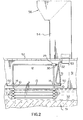
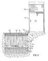
- FIGS 2 and 3 illustrate one typical open system installation of the device consisting of a number of modular and removable units.
- lamp sections 2 are disposed below fluid 57 in an open containment channel 21 and arranged so that their axial alignment parallels the fluid flow direction.
- the lamp sections in each nodule are supported in position by means of reflectors 13 which themselves at their free ends are supported by frame members 50 which are transverse of the channel.
- the upper surface of the channel is covered by safety grid 52.
- Adjacent the side of the channel is a control box and power supply 54 having access door 55 and display 56 as discussed below.
- Electrical distribution conduit 53 extends from the control box 54 and across the open channel.
- Cables 31 for each of the nodules are connected to corresponding leads (not shown) within the conduit and control box and are individually connected by means of male connecters 32. It will thus be apparent that individual modules can be disconnected either at connecter 30 or 32 and vertically removed from the reminder of the array of lamp sections.
- Display panel 56 if employed, advantageously can include a grid pattern of lights or signals which corresponds in number and array pattern to the configuration of the lamp units in the operating device.
- each light or signalling device in the display panel is dedicated to and forms part of the electrical circuit for each of the numerous lamp sections, should one lamp in a module burn out, the particular nodule and the specific burned cut lamp can be readily and conveniently visually determined upon checking the display grid.
Abstract

Description
- This invention relates to an ultraviolet fluid purification or sterilization device.
- The ability of ultraviolet light to kill or destroy micro-organisms in air or liquid is well known. Ultraviolet light has successfully been employed as a purifying or sterilizing technique in both domestic and small-scale industrial applications. Its germicidal qualities, however, in any given application, depends in part upon the intensity of the ultraviolet light, the fluid exposure time to the light and the light transmission quality of the fluid itself. There has been a recent trend towards "thin film" ultraviolet radiation whereby a thin film or layer of the fluid to be purified is constrained to pass in close proximity to an elongate ultraviolet ray emitting source which itself is normally covered or surrounded by a protective quartz jacket or sleeve. The thin film passage of the fluid may be in a direction which parallels the elongate axis of the ultraviolet lamp as disclosed, for example, in Canadian Patent 1,062,437 - Lewis, issued September 18, 1979 or perpendicular thereto as disclosed, for example, in United States Patent 3,837,800 - Wood, issued September 24, 1974. Both of these thin film. ultraviolet purifying or sterilizing designs are intended for use in a closed fluid supply system wherein the fluid which is in close proximity to the lamp units does not contact the lamp ends and their attendant electrical interconnection with a source of electric power. In other words, the free ends of the ultraviolet lamps within its associated sleeve or jacket of a closed system are not designed to be themselves immersed in water although removal and replacement of burned cut lamps can be a relatively simple task. In addition to their inability to be water immersed, these known thin-film closed ultraviolet purification systems are relatively costly to manufacture and individually limited in handling many industrial fluid throughput dictates found in existing water purification plants and waste water treatment facilities. Moreover, whether or not ultraviolet irradiation is achieved using the thin-film principle, closed systems are not readily adaptable and installed in existing water or effluent facilities where the fluid to be treated flows through open containment streams, channels, sluices or the like.
- The novel ultraviolet purification or sterilization device of this invention is so designed that all lamp sections comprising elongate lamp units and their associated lamp unit receiving sockets can be totally water immersed yet permit ready withdrawal and removal of a lamp in the lamp unit in the event of burn-out. Further, the. novel device can be used in either a closed or open system as above described and if desired, the array of parallel lamp sections can be positioned sufficiently close to one another in order to take advantage of the thin-film treatment principle when either the axes of the light units extend in a direction parallel to the fluid flow or are normal to this fluid flow.
- In accordance with yet another aspect of this invention, each row of the parallel rows of spaced apart and parallel lamp sections which themselves each include a lamp unit and its end pair of water impermiable lamp unit receiving sockets can be modularized. This permits the ready withdrawal and replacement of one row of lamp sections as a modular unit independently of the others which can remain operational; removal and replacement being normally undertaken where one or more lamps in the module has burned-out.
- Another feature of this invention resulting from modularizing each row of fluid immersible lamp sections, is that the number of required rows needed for any given open system application can be readily met merely by adding or subtracting one or more of the modules. Thus, for a given width of a containment stream in which the lamp sections are to be positioned in a direction parallel to the flow, the required number of rcws can be readily predetermined. where the lamp sections are at right angles to the fluid flow direction, additional modules can be added to either the upstream or downstream ends of the device. Transverse modular additions would normally take place in situations where additional ultraviolet irradiation is required in order to ensure full and complete germicidal irradiation. It will also be apparent that this desired result can also be achieved by separately locating two or more devices in the same fluid stream. Further, it is also possible to arrange the axes of the lamp sections in one device parallel to the stream flow whilst the lamp section axes of the other device is in a perpendicular relationship. The number and spacing between the lamp sections in each row can also be increased or decreased to meet the germicidal dictates for any given installation and the cross-sectional configuration (e.g. depth) of the containment stream in which the lamp sections are immersed.
- The present invention can be described in general terms as an ultraviolet purifying device comprising a supporting frame, parallel rows of spaced apart and parallel lamp sections wherein each of said lamp sections includes a pair of opposed, fluid impermeable lamp unit receiving sockets and a lamp unit which extends therebetween. Each said lamp unit itself comprises an inner, elongate, cylindrical ultraviolet ray emitting lamp and an outer co-axil and substantially co-extensive cylindrical sleeve. There is also provided means for supporting said lamp sections in each row in spaced apart relationship, electrical conductor means for said lamps and lamp withdrawal fluid impermeable closure means on at least one of each pair of said sockets.
- As indicated above, and if desired, the novel device can be modularized by the inclusion of means for separately withdrawing one row of said lamp sections from the remaining rows of said lamp sections. Accordingly, and with regard to this modular feature, the novel device can also be generally described as a ultraviolet fluid purifying device which has a support frame and a plurality of separately removable fluid immersable ultraviolet lamp nodules which are positioned thereon and wherein each module includes a pair of opposed, spaced apart and parallel lamp unit supporting leg sections; opposed and equally spaced apart pairs of fluid impermeable lamp unit receiving sockets on said leg sections; lamp units which are supported by and which extend between each pair of said lamp unit receiving sockets; each lamp unit comprising an ultraviolet ray emitting lamp and its associated jacket as previously described; electrical contact means included in each of said sockets which are in electrical engagement with said lamps and, like before, at least one socket in each of said socket pairs at its end remote from said lamp unit including lamp withdrawal fluid impermeable closure means.
- Advantageously, the neans for supporting the lamp sections or in the nodular configuration, the supporting leg sections can be constructed from hollow conduit. Additionally, an upper frame section also composed of hollow conduit can extend above and communicate with the hollow leg sections and thereby internally carry the electrical conductor leads for the electrical contact means included in the sockets for the lamps. Moreover, these leads cn the upper frame can all commonly terminate in an electrical connector means which electrically couples the nodule to a remote power supply. The upper frame itself can conveniently function as a module withdrawal neans as it need only be hand grasped and pulled cut. A reflector plate used to reflect back ultraviolet light and protect operating personnel from ultraviolet light can also be positioned above the lamp sections or lamp units in each module and can be conveniently carried by the same means which supports the lamp sections.
- The spacing between lamp sections or lamp units in each row normally but not necessarily should be uniform with the selected spacing ideally predetermined in order to meet the germicidal conditions in which it will operate. Further, it will also be appreciated that neighbouring lamp sections or lamp units in each row may be parallel or diagonally offset; the latter configuration producing the tightest packing of the array of lamp units or lamp sections.
- In the accompanying drawings which illustrate one working embodiment of this invention:
- Figure 1 is a side view of an operating nodule illustrating the lamp sections, reflector plate and upper frame section and also showing internal detail in partial cut-away;
- Figure 2 is a similar view to that of Figure 1 illustrating a nodule when positioned in a effluent channel and when connected to its electrical control panel; and
- Figure 3 is an end view of the operational device of Figure 2 but now illustrating a plurality of nodules with lamp sections arranged in a direction parallel to the fluid flow.
- For ease of understanding, the same reference numerals have been used in the drawings to depict similar component parts.
- Referring to Figure 1, the ultraviolet fluid sterilization or purification module therein illustrated is generally indicated by reference numeral 1. A plurality of equally spaced apart and
parallel lamp sections 2 are arranged in a vertical row as shown. These lamp sections each includelamp units 3 which have an inner, elongate, cylindrical ultraviolet ray emitting lamp 4.( A typical lamp suitable for this purpose is one available from Voltare Inc. of Fairfield, Conn., U.S.A., which is a slim line single pin lamp sold under Model G36T6L.) Surroundinglamp 4 is an outer, coaxial and substantially co-extensive cylindrical jacket orsleeve 5 which protectslamp 4 whilst permitting the transmittance of the ultraviolet rays therethrough. Theparticular lamp 4 illustrated is provided with asingle pin contact 6 at either of its ends (only one being shown in Figure 1). - Each of the
lamp units 3 at its ends terminates in pairs of opposed fluid impermeable lampunit receiving sockets 7. As discussed in greater detail below, this arrangement permits full fluid immersion of all of the lamp sections with includedlamps 4 interior thereof remaining dry. Lamp section supporting means or legsections 10 support and interconnect the lamp sections in spaced relationship. As best seen in Figure 1, an optional cross-brace 11 can interconnectlegs 10 at their lower extremities in order to impart further strength to the nodule and relieve pressure uponlamp units 3. Thelegs 10 can be made up of hollow conduit which interconnects thenumerous sockets 7 and as illustrated, can extend above the upper most of the lamp sections in a module so as to interconnect the two legs by means ofupper frame section 12. An inverted U-shaped elongate channel orreflector component 13 is positioned intermediateupper frame 12 and theupper lamp section 2.Collar 14 and setscrew 15 which are attached toreflector 13 serves to fixedly secure the reflector above and parallel to the lamp sections and also impart further structural rigidity to the nodule.Reflector 13 serves the three-fold purpose of reflecting back rays emitted from the lamp sections, protecting service or maintenance personnel operating in the vicinity of the device and supporting the device in the frame. - With particular reference to the cross-sectional detail of the
socket 7 depicted in Figure 1, the socket at its endadjacent lamp unit 3 is provided with fluid tightcircular sealing gasket 20. Lamp withdrawal fluid impermeable closure means is also provided at the other end ofsocket 7 and in the specific embodiment illustrated, includesend plug 22 andplug protrusion 23.Fluid sealing gasket 21 is disposed betweenplug 22 andsocket 7 so that the interior of the socket remains dry. Exterior ofplug 22 and serving to hold it in position is snap washer 28. - Since the illustrated
lamps 4 havesingle contact pins 6 at either of their ends, fourelectrical leads protrusion 23 at its free end carries metalized strip orclip 24 which is biased away fromplug 22 by means ofspring 25 and towardscontact pin 6. As illustrated, lead 33 terminates in electrical abutting contact withclip 24 at 26. It will be evident that upon removal ofwasher 28 andplug 22 withspring 25 andclip 24, thatlamp 4 can be withdrawn outwardly of jacket orsleeve 5 through the open end ofsocket 7. While not shown in Figure 1, the opposite socket to the socket shown- in cross-section can be constructed in an identical manner and in which case the contact lead would belead 33a. It will be also apparent, however, that the free end of this socket can be permanently sealed so that thelamp 4 can only be withdrawn from one end of each pair of opposed sockets. - The other or upper ends of the leads terminate in
electrical connecter 29 in a known manner and as illustrated, are electrically inter-connected topower cord 31 by complimentarymale connecter 30. The nodule thus, if desired, can be readily separated from its power supply merely by withdrawingmale connecter 30 at this point. - Figures 2 and 3 illustrate one typical open system installation of the device consisting of a number of modular and removable units. As shown,
lamp sections 2 are disposed belowfluid 57 in anopen containment channel 21 and arranged so that their axial alignment parallels the fluid flow direction. The lamp sections in each nodule are supported in position by means ofreflectors 13 which themselves at their free ends are supported byframe members 50 which are transverse of the channel. The upper surface of the channel is covered bysafety grid 52. Adjacent the side of the channel is a control box andpower supply 54 havingaccess door 55 anddisplay 56 as discussed below.Electrical distribution conduit 53 extends from thecontrol box 54 and across the open channel.Cables 31 for each of the nodules are connected to corresponding leads (not shown) within the conduit and control box and are individually connected by means ofmale connecters 32. It will thus be apparent that individual modules can be disconnected either atconnecter -
Display panel 56, if employed, advantageously can include a grid pattern of lights or signals which corresponds in number and array pattern to the configuration of the lamp units in the operating device. As each light or signalling device in the display panel is dedicated to and forms part of the electrical circuit for each of the numerous lamp sections, should one lamp in a module burn out, the particular nodule and the specific burned cut lamp can be readily and conveniently visually determined upon checking the display grid. - Because the nodules can be quickly and readily removed and replaced, the lamp sections in each module, upon withdrawal, can be cleansed in a matter of seconds or minutes. Thus, the need for cumbersome lamp "wipers" as known in the art is not required.
- It will be appreciated that variations to the construction of the specifically disclosed lamp section assembly having means permitting fluid sealed lamp withdrawal means can be made without departing from the spirit or scope of this invention. Similarly, variations or alterations to the construction of the nodular units as herein specifically disclosed can also be made falling within the overall inventive concept as elsewhere presented in this disclosure.
Claims (10)
Priority Applications (1)
| Application Number | Priority Date | Filing Date | Title |
|---|---|---|---|
| AT82201512T ATE19231T1 (en) | 1981-11-30 | 1982-11-26 | DEVICE FOR CLEANING FLUIDA USING U.V. RAYS. |
Applications Claiming Priority (2)
| Application Number | Priority Date | Filing Date | Title |
|---|---|---|---|
| CA000391198A CA1163086A (en) | 1981-11-30 | 1981-11-30 | Ultraviolet fluid purifying device |
| CA391198 | 1981-11-30 |
Publications (2)
| Publication Number | Publication Date |
|---|---|
| EP0080780A1 true EP0080780A1 (en) | 1983-06-08 |
| EP0080780B1 EP0080780B1 (en) | 1986-04-16 |
Family
ID=4121530
Family Applications (1)
| Application Number | Title | Priority Date | Filing Date |
|---|---|---|---|
| EP82201512A Expired EP0080780B1 (en) | 1981-11-30 | 1982-11-26 | An ultraviolet fluid purifying device |
Country Status (5)
| Country | Link |
|---|---|
| US (1) | US4482809A (en) |
| EP (1) | EP0080780B1 (en) |
| AT (1) | ATE19231T1 (en) |
| CA (1) | CA1163086A (en) |
| DE (1) | DE3270676D1 (en) |
Cited By (6)
| Publication number | Priority date | Publication date | Assignee | Title |
|---|---|---|---|---|
| EP0249450A2 (en) * | 1986-06-10 | 1987-12-16 | FISCHER & PORTER COMPANY | Ultraviolet water treatment apparatus |
| FR2657277A1 (en) * | 1988-07-07 | 1991-07-26 | Ultraviolet Purification Syste | METHOD AND INSTALLATION FOR CLEANING ULTRAVIOLET LAMPS USED FOR DISINFECTING WASTEWATER. |
| US5725757A (en) * | 1995-01-16 | 1998-03-10 | Otv Omnium De Traitements Et De Valorisation (Societe Anonyme) | Reactor for UV radiation for the treatment of liquids |
| WO1998027011A1 (en) * | 1996-12-19 | 1998-06-25 | Wedeco Gmbh | Uv disinfecting device advantageous for fluid flows |
| US6245570B1 (en) | 1991-05-08 | 2001-06-12 | Baxter International Inc. | Container for irradiation of blood products |
| US6500312B2 (en) | 1998-12-30 | 2002-12-31 | Wedeco Ag | Device and method for UV-irradiation, especially for disinfecting, flowing liquids with reduced UV-transmission |
Families Citing this family (90)
| Publication number | Priority date | Publication date | Assignee | Title |
|---|---|---|---|---|
| US4879489A (en) * | 1986-02-10 | 1989-11-07 | Photo Redux Corp. | Radiation-emitting devices |
| US4853581A (en) * | 1986-02-10 | 1989-08-01 | Photo Redux Corp. | Radiation-emitting devices |
| US4835444A (en) * | 1986-02-10 | 1989-05-30 | Photo Redux Corp. | Radiation-emitting devices |
| US4752401A (en) * | 1986-02-20 | 1988-06-21 | Safe Water Systems International, Inc. | Water treatment system for swimming pools and potable water |
| US4825083A (en) * | 1986-06-10 | 1989-04-25 | Arlat Inc. | Ultraviolet water treatment apparatus |
| US4767932A (en) * | 1986-09-26 | 1988-08-30 | Ultraviolet Purification System, Inc. | Ultraviolet purification device |
| US4876014A (en) * | 1988-03-21 | 1989-10-24 | Water Systems Development Corporation | Method and apparatus for producing ultrapure water |
| US4872980A (en) * | 1988-09-13 | 1989-10-10 | Trojan Technologies, Inc. | Fluid purification device |
| US5006244A (en) * | 1988-09-13 | 1991-04-09 | Trojan Technologies, Inc. | Fluid purification device |
| DE4007898C1 (en) * | 1990-03-13 | 1991-04-18 | Rudolf Tann Ch Wiesmann | |
| US5019256A (en) * | 1990-10-19 | 1991-05-28 | Fischer & Porter Company | Ultraviolet lamp rack assembly |
| US5147532A (en) * | 1991-02-21 | 1992-09-15 | Leek Jr Kenneth F | Domestic grey water purifier using diverter and UV filter treater with preheater |
| DE4119725C2 (en) * | 1991-06-16 | 1997-09-18 | Delta Uv Gmbh | Device for irradiating water in the free-level drain with UV light |
| DE4220088C2 (en) * | 1992-06-19 | 1997-06-05 | Delta Uv Gmbh | Device for the UV irradiation of water |
| US6264888B1 (en) * | 1992-10-09 | 2001-07-24 | National Jewish Center For Immunology And Respiratory Medicine | Ultraviolet germicidal apparatus and method |
| US5368826A (en) * | 1992-12-04 | 1994-11-29 | Infilco Degremont, Inc. | Control apparatus for fluid disinfection modules and systems |
| US5332388A (en) * | 1992-12-04 | 1994-07-26 | Infilco Degremont, Inc. | Ultraviolet disinfection module |
| USRE36896E (en) * | 1993-03-05 | 2000-10-03 | Trojan Technologies Inc. | Fluid treatment system and process |
| US5418370A (en) * | 1993-03-05 | 1995-05-23 | Trojan Technologies, Inc. | Fluid treatment system and process |
| US5514871A (en) * | 1994-01-13 | 1996-05-07 | Trojan Technologies | Optical radiation sensor device |
| US5471063A (en) * | 1994-01-13 | 1995-11-28 | Trojan Technologies, Inc. | Fluid disinfection system |
| DE4417139C2 (en) * | 1994-05-17 | 1996-04-18 | Rudolf Wiesmann | Device and system for disinfecting flowing liquids and using the same |
| US5504335A (en) * | 1994-10-17 | 1996-04-02 | Trojan Technologies, Inc. | Fluid treatment device and method |
| US5539209A (en) * | 1994-10-17 | 1996-07-23 | Trojan Technologies Inc. | Method of cleaning fouling materials from a radiation module |
| US5660719A (en) * | 1994-12-23 | 1997-08-26 | Kurtz; Mark E. | Ultraviolet light apparatus for fluid purification |
| US5792433A (en) * | 1995-03-13 | 1998-08-11 | Photoscience Japan Corporation | Light irradiating device with easily replaceable light irradiating lamps |
| US5997812A (en) * | 1996-06-20 | 1999-12-07 | Coolant Treatment Systems, L.L.C. | Methods and apparatus for the application of combined fields to disinfect fluids |
| US6083387A (en) * | 1996-06-20 | 2000-07-04 | Burnham Technologies Ltd. | Apparatus for the disinfection of fluids |
| US5846437A (en) * | 1997-01-03 | 1998-12-08 | Trojan Technologies Inc. | Increasing turbulent mixing in a UV system |
| US6015229A (en) * | 1997-09-19 | 2000-01-18 | Calgon Carbon Corporation | Method and apparatus for improved mixing in fluids |
| US6144175A (en) * | 1997-11-05 | 2000-11-07 | Parra; Jorge M. | Low-voltage ballast-free energy-efficient ultraviolet material treatment and purification system and method |
| US6411041B1 (en) * | 1999-06-02 | 2002-06-25 | Jorge M. Parra | Non-thermionic fluorescent lamps and lighting systems |
| US6465971B1 (en) | 1999-06-02 | 2002-10-15 | Jorge M. Parra | Plastic “trofer” and fluorescent lighting system |
| KR100523009B1 (en) | 1999-06-04 | 2005-10-20 | 헨리 코즐로프스키 | Apparatus for ultraviolet light treatment of fluids |
| CA2275467C (en) * | 1999-06-18 | 2004-03-02 | Biophys Inc. | Method and apparatus for flowing sterile fluid membranes |
| US6830697B1 (en) | 1999-09-03 | 2004-12-14 | Trojan Technologies Inc. | Fluid treatment system, radiation source assembly and radiation source module |
| US6518577B1 (en) * | 1999-10-01 | 2003-02-11 | Trojan Technologies Inc. | Optical radiation sensor system with cleaning device |
| KR20020060778A (en) * | 1999-12-06 | 2002-07-18 | 홀던 데이비드 | An on-line device for predicting at least one fluid flow parameter in a process |
| KR20020062347A (en) | 1999-12-17 | 2002-07-25 | 트로잰 테크놀로지스 인코포레이티드 | Radiation source module |
| DE60038629D1 (en) | 1999-12-17 | 2008-05-29 | Trojan Techn Inc | OPTICAL RADIATION METER |
| EP1289889B1 (en) * | 2000-06-06 | 2008-07-30 | Trojan Technologies Inc. | Fluid mixing device |
| US7390406B2 (en) * | 2000-12-15 | 2008-06-24 | Trojan Technologies Inc. | Fluid treatment system and radiation sources module for use therein |
| ITMI20010968A1 (en) * | 2001-05-10 | 2002-11-10 | Centonze Nicola | SINGLE OR COEXTRUDED FILM FOR TEMPORARY OR PERMANENT PROTECTION OF SURFACES IN GENERAL WITH AN AESTHETIC-FUNCTIONAL ASPECT SIMILAR TO THE CAR |
| US6719491B2 (en) | 2001-08-03 | 2004-04-13 | Trojan Technologies Inc. | Fluid level control system |
| US6663318B2 (en) | 2001-08-03 | 2003-12-16 | Trojan Technologies, Inc. | Fluid level control system |
| CN1286734C (en) * | 2001-09-20 | 2006-11-29 | 特洛伊人技术公司 | Fluid treatment system including reactor screw array |
| US6773584B2 (en) | 2001-10-17 | 2004-08-10 | Honeywell International Inc. | Apparatus for disinfecting water using ultraviolet radiation |
| US7169311B2 (en) * | 2001-10-17 | 2007-01-30 | Honeywell International, Inc. | Apparatus for disinfecting water using ultraviolet radiation |
| EP1487952A1 (en) | 2002-03-20 | 2004-12-22 | Trojan Technologies Inc. | Cleaning formulation and method of cleaning surfaces |
| US20050069463A1 (en) * | 2002-05-07 | 2005-03-31 | Kurtz Mark E. | Fluid disinfection apparatus |
| US6956220B2 (en) * | 2002-06-19 | 2005-10-18 | Trojan Technologies Inc. | Fluid treatment system and radiation sources module for use therein |
| US6784440B2 (en) | 2002-07-26 | 2004-08-31 | Boc, Inc. | Food sanitizing cabinet |
| EP1575669B1 (en) * | 2002-08-09 | 2010-10-27 | Primos OÜ | A laser device for treatment of infections |
| CA2501517A1 (en) * | 2002-10-09 | 2004-04-22 | Trojan Technologies Inc. | Ultraviolet fluid treatment system |
| US7160566B2 (en) | 2003-02-07 | 2007-01-09 | Boc, Inc. | Food surface sanitation tunnel |
| EP1737501A4 (en) * | 2004-03-12 | 2009-09-02 | Trojan Techn Inc | Fluid treatment system |
| CN1942402B (en) * | 2004-04-15 | 2012-04-25 | 特洛伊人技术公司 | Fluid treatment system |
| CA2563425A1 (en) * | 2004-04-19 | 2005-10-27 | Trojan Technologies Inc. | Optical radiation sensor system and method for measuring radiation transmittance of a fluid |
| WO2006002521A1 (en) | 2004-06-30 | 2006-01-12 | Trojan Technologies Inc. | Radiation sensor device and fluid treatment system containing same |
| US7159264B2 (en) | 2004-12-10 | 2007-01-09 | Calgon Carbon Corporation | Scraper for cleaning tubular members |
| JP2006187697A (en) * | 2005-01-04 | 2006-07-20 | Hitachi Ltd | Filtration cleaning apparatus |
| US7241380B2 (en) * | 2005-06-15 | 2007-07-10 | Reiling Dennis R | Ultraviolet treatment unit and septic tank system |
| CA2621301C (en) * | 2005-08-31 | 2013-04-30 | Trojan Technologies Inc. | Ultraviolet radiation lamp and source module and treatment system containing same |
| US20090280027A1 (en) * | 2006-03-27 | 2009-11-12 | Hayman Jr John J | Photocatalytic air treatment system and method |
| US20070251812A1 (en) * | 2006-03-27 | 2007-11-01 | Hayman John J Jr | Photocatalytic air treatment system and method |
| US8679416B2 (en) | 2006-08-17 | 2014-03-25 | Trojan Technologies | Fluid treatment system |
| CA2668588C (en) | 2006-11-06 | 2013-01-08 | Trojan Technologies | Fluid treatment system |
| US8529770B2 (en) * | 2007-09-27 | 2013-09-10 | Water Of Life, Llc. | Self-contained UV-C purification system |
| US7862728B2 (en) | 2007-09-27 | 2011-01-04 | Water Of Life, Llc. | Ultraviolet water purification system |
| CN101896264A (en) | 2007-12-14 | 2010-11-24 | 特洛伊科技有限公司 | Radiation source assembly and fluid handling system |
| US7800310B2 (en) * | 2008-03-18 | 2010-09-21 | Butters Brian E | End-to-end lamp assembly and method of manufacturing same |
| ES2466348T3 (en) * | 2008-11-26 | 2014-06-10 | Calgon Carbon Corporation | Method and apparatus for use in mixing elements in a UV disinfection system for wastewater / recycled water |
| US20120097187A1 (en) | 2009-03-13 | 2012-04-26 | Trojan Technologies | Cleaning apparatus, radiation source module and fluid treatment system |
| EP2498925A4 (en) | 2009-11-12 | 2014-06-18 | Trojan Techn Inc | Cleaning apparatus. radiation source module and fluid treatment system |
| AU2011305003A1 (en) | 2010-09-10 | 2013-05-02 | Trojan Technologies | Radiation source assembly |
| CN102728293A (en) | 2010-10-04 | 2012-10-17 | 特洁安科技有限公司 | Sleeve holder assembly |
| EP2651550B1 (en) | 2010-12-16 | 2021-04-14 | Trojan Technologies | Radiation source module and fluid treatment system |
| CN104145122A (en) | 2012-01-20 | 2014-11-12 | 特洁安技术公司 | Fluid flow modifier and fliud treatment system incorporating same |
| WO2013123590A1 (en) | 2012-02-23 | 2013-08-29 | Trojan Technologies | Radiation source cleaning system and module containing same |
| DE102012008733A1 (en) | 2012-05-04 | 2013-11-07 | Xylem Water Solutions Herford GmbH | UV water treatment plant with open channel |
| CA2894215A1 (en) | 2012-12-07 | 2014-06-12 | Trojan Technologies | Cleaning apparatus |
| JP6535004B2 (en) | 2013-08-29 | 2019-06-26 | クリスタル アイエス,インコーポレーテッドCrystal Is,Inc. | Apparatus and method for liquid treatment of uniform dispersion of ultraviolet light |
| KR20170095934A (en) * | 2014-12-12 | 2017-08-23 | 코닌클리케 필립스 엔.브이. | Cooling apparatus for cooling a fluid by means of surface water |
| CN204481158U (en) * | 2015-03-19 | 2015-07-15 | 中山市威德轻工机电制品有限公司 | Earth connection divides the sterilizer of ultraviolet radiation for water body of body nut and application thereof |
| EP3081534B1 (en) * | 2015-04-16 | 2021-03-03 | Trojan Technologies Inc. | Radiation source module and fluid treatment system |
| BR112017023643A2 (en) * | 2015-05-06 | 2018-07-17 | Koninklijke Philips Nv | assembly, vessel and method of temporarily preventing exposure of a surface of an object to water |
| EP3517506A1 (en) | 2018-01-24 | 2019-07-31 | Xylem Europe GmbH | Uv water treatment plant with open channel and water level control |
| DE102019114168A1 (en) * | 2019-05-27 | 2020-12-03 | Rheinisch-Westfälische Technische Hochschule (Rwth) Aachen | Photoreactor and photoreactor system with photoreactor |
| KR20230107657A (en) | 2020-11-14 | 2023-07-17 | 마크 안소니 인터내셔날 에스알엘 | How to sterilize fermented beverages |
| CN114014406A (en) * | 2021-11-09 | 2022-02-08 | 宋佳威 | Environment-friendly biological wastewater automatic purification treatment system and use method thereof |
Citations (3)
| Publication number | Priority date | Publication date | Assignee | Title |
|---|---|---|---|---|
| FR421296A (en) * | 1910-10-10 | 1910-12-17 | Marius Paul Otto | Apparatus for sterilizing water by ultraviolet rays |
| FR434069A (en) * | 1911-04-11 | 1912-01-24 | Paul Gabriel Triquet | Apparatus for the industrial sterilization of water by means of electric mercury lamps with quartz tubes, immersed in water |
| DE855521C (en) * | 1950-12-28 | 1952-11-13 | Siemens Ag | Method and device for treating, preferably cleaning, sewage and other fluids |
Family Cites Families (5)
| Publication number | Priority date | Publication date | Assignee | Title |
|---|---|---|---|---|
| US3462597A (en) * | 1966-07-29 | 1969-08-19 | Ultra Dynamics Corp | Ultraviolet fluid purifier having manually operable wiper means |
| US3948772A (en) * | 1975-04-16 | 1976-04-06 | Sidney Ellner | Split stream ultraviolet purification device |
| US4255663A (en) * | 1977-03-24 | 1981-03-10 | Lewis James H | Disposable liquid sterilizer unit |
| US4367410A (en) * | 1979-07-09 | 1983-01-04 | Pure Water Systems, Inc. | Waste purification apparatus and method |
| US4400270A (en) * | 1980-04-18 | 1983-08-23 | Adco Aerospace, Inc. | Ultraviolet apparatus for disinfection and sterilization of fluids |
-
1981
- 1981-11-30 CA CA000391198A patent/CA1163086A/en not_active Expired
-
1982
- 1982-11-26 EP EP82201512A patent/EP0080780B1/en not_active Expired
- 1982-11-26 DE DE8282201512T patent/DE3270676D1/en not_active Expired
- 1982-11-26 AT AT82201512T patent/ATE19231T1/en not_active IP Right Cessation
-
1984
- 1984-05-18 US US06/611,912 patent/US4482809A/en not_active Expired - Lifetime
Patent Citations (3)
| Publication number | Priority date | Publication date | Assignee | Title |
|---|---|---|---|---|
| FR421296A (en) * | 1910-10-10 | 1910-12-17 | Marius Paul Otto | Apparatus for sterilizing water by ultraviolet rays |
| FR434069A (en) * | 1911-04-11 | 1912-01-24 | Paul Gabriel Triquet | Apparatus for the industrial sterilization of water by means of electric mercury lamps with quartz tubes, immersed in water |
| DE855521C (en) * | 1950-12-28 | 1952-11-13 | Siemens Ag | Method and device for treating, preferably cleaning, sewage and other fluids |
Cited By (10)
| Publication number | Priority date | Publication date | Assignee | Title |
|---|---|---|---|---|
| EP0249450A2 (en) * | 1986-06-10 | 1987-12-16 | FISCHER & PORTER COMPANY | Ultraviolet water treatment apparatus |
| EP0249450A3 (en) * | 1986-06-10 | 1989-08-30 | FISCHER & PORTER COMPANY | Ultraviolet water treatment apparatus |
| FR2657277A1 (en) * | 1988-07-07 | 1991-07-26 | Ultraviolet Purification Syste | METHOD AND INSTALLATION FOR CLEANING ULTRAVIOLET LAMPS USED FOR DISINFECTING WASTEWATER. |
| US6245570B1 (en) | 1991-05-08 | 2001-06-12 | Baxter International Inc. | Container for irradiation of blood products |
| US6696023B2 (en) | 1991-05-08 | 2004-02-24 | Baxter International Inc. | Apparatus for irradiation of blood products |
| US5725757A (en) * | 1995-01-16 | 1998-03-10 | Otv Omnium De Traitements Et De Valorisation (Societe Anonyme) | Reactor for UV radiation for the treatment of liquids |
| WO1998027011A1 (en) * | 1996-12-19 | 1998-06-25 | Wedeco Gmbh | Uv disinfecting device advantageous for fluid flows |
| DE19653083B4 (en) * | 1996-12-19 | 2005-09-08 | Wedeco Ag Water Technology | Streamlined UV disinfection device |
| US6500312B2 (en) | 1998-12-30 | 2002-12-31 | Wedeco Ag | Device and method for UV-irradiation, especially for disinfecting, flowing liquids with reduced UV-transmission |
| US6565757B1 (en) | 1998-12-30 | 2003-05-20 | Wedeco Ag | UV radiation device, especially for disinfecting liquids with reduced UV transmission |
Also Published As
| Publication number | Publication date |
|---|---|
| DE3270676D1 (en) | 1986-05-22 |
| CA1163086A (en) | 1984-03-06 |
| ATE19231T1 (en) | 1986-05-15 |
| EP0080780B1 (en) | 1986-04-16 |
| US4482809A (en) | 1984-11-13 |
Similar Documents
| Publication | Publication Date | Title |
|---|---|---|
| US4482809A (en) | Ultraviolet fluid purifying device | |
| CA2047084C (en) | Ultraviolet lamp rack assembly | |
| US4757205A (en) | Ultraviolet water treatment apparatus | |
| USRE34513E (en) | Ultraviolet liquid purification system | |
| CA1327877C (en) | Fluid purification device | |
| US5660719A (en) | Ultraviolet light apparatus for fluid purification | |
| AU767926B2 (en) | Apparatus for ultraviolet light treatment of fluids | |
| CA2099063A1 (en) | Control apparatus for fluid disinfection modules and systems | |
| US4825083A (en) | Ultraviolet water treatment apparatus | |
| CA2390973A1 (en) | Uv radiation device for treating fluids with a simplified radiation chamber | |
| WO2010069072A1 (en) | Radiation source cartridge and module containing same | |
| US5792433A (en) | Light irradiating device with easily replaceable light irradiating lamps | |
| WO2023128392A1 (en) | Flowing water sterilization apparatus for irradiating ultraviolet rays to flowing water pipe in three-dimensional form | |
| EP2651550B1 (en) | Radiation source module and fluid treatment system | |
| CN214880374U (en) | Ultraviolet disinfection system for treating industrial wastewater | |
| CN108569744B (en) | Ultraviolet sterilization device for circulating culture sewage treatment | |
| KR200172701Y1 (en) | Ultraviolet radiation disinfector with diffuser | |
| CA2718912C (en) | End-to-end lamp assembly and method of manufacturing same | |
| US3366441A (en) | Ultraviolet system for control of algae and slime within humidity control and similar systems | |
| JPH08243555A (en) | Photoirradiation device with photoirradiation lamp easy to replace | |
| US6620318B1 (en) | Modular disinfection system for fluids | |
| WO2023171850A1 (en) | Air purification device equipped with cylindrical photocatalyst filter | |
| CN202924790U (en) | Vertical installation type ultraviolet sterilization device | |
| RU2398740C1 (en) | Uv radiation section and uv water treatment system based on said section | |
| WO2011115461A2 (en) | Sterilization apparatus for water purifier |
Legal Events
| Date | Code | Title | Description |
|---|---|---|---|
| PUAI | Public reference made under article 153(3) epc to a published international application that has entered the european phase |
Free format text: ORIGINAL CODE: 0009012 |
|
| AK | Designated contracting states |
Designated state(s): AT BE CH DE FR GB IT LI LU NL SE |
|
| 17P | Request for examination filed |
Effective date: 19831201 |
|
| RAP1 | Party data changed (applicant data changed or rights of an application transferred) |
Owner name: TROJAN TECHNOLOGIES INC. |
|
| GRAA | (expected) grant |
Free format text: ORIGINAL CODE: 0009210 |
|
| AK | Designated contracting states |
Kind code of ref document: B1 Designated state(s): AT BE CH DE FR GB IT LI LU NL SE |
|
| PG25 | Lapsed in a contracting state [announced via postgrant information from national office to epo] |
Ref country code: AT Effective date: 19860416 |
|
| REF | Corresponds to: |
Ref document number: 19231 Country of ref document: AT Date of ref document: 19860515 Kind code of ref document: T |
|
| REF | Corresponds to: |
Ref document number: 3270676 Country of ref document: DE Date of ref document: 19860522 |
|
| ITF | It: translation for a ep patent filed |
Owner name: ING. A. GIAMBROCONO & C. S.R.L. |
|
| ET | Fr: translation filed | ||
| PG25 | Lapsed in a contracting state [announced via postgrant information from national office to epo] |
Ref country code: LU Free format text: LAPSE BECAUSE OF NON-PAYMENT OF DUE FEES Effective date: 19861130 |
|
| PLBE | No opposition filed within time limit |
Free format text: ORIGINAL CODE: 0009261 |
|
| STAA | Information on the status of an ep patent application or granted ep patent |
Free format text: STATUS: NO OPPOSITION FILED WITHIN TIME LIMIT |
|
| 26N | No opposition filed | ||
| ITTA | It: last paid annual fee | ||
| EAL | Se: european patent in force in sweden |
Ref document number: 82201512.9 |
|
| PGFP | Annual fee paid to national office [announced via postgrant information from national office to epo] |
Ref country code: CH Payment date: 19991122 Year of fee payment: 18 |
|
| PGFP | Annual fee paid to national office [announced via postgrant information from national office to epo] |
Ref country code: BE Payment date: 19991125 Year of fee payment: 18 |
|
| PGFP | Annual fee paid to national office [announced via postgrant information from national office to epo] |
Ref country code: SE Payment date: 19991129 Year of fee payment: 18 |
|
| PGFP | Annual fee paid to national office [announced via postgrant information from national office to epo] |
Ref country code: NL Payment date: 19991130 Year of fee payment: 18 |
|
| PGFP | Annual fee paid to national office [announced via postgrant information from national office to epo] |
Ref country code: DE Payment date: 19991220 Year of fee payment: 18 |
|
| PG25 | Lapsed in a contracting state [announced via postgrant information from national office to epo] |
Ref country code: SE Free format text: THE PATENT HAS BEEN ANNULLED BY A DECISION OF A NATIONAL AUTHORITY Effective date: 20001129 |
|
| PG25 | Lapsed in a contracting state [announced via postgrant information from national office to epo] |
Ref country code: LI Free format text: LAPSE BECAUSE OF NON-PAYMENT OF DUE FEES Effective date: 20001130 Ref country code: CH Free format text: LAPSE BECAUSE OF NON-PAYMENT OF DUE FEES Effective date: 20001130 Ref country code: BE Free format text: LAPSE BECAUSE OF NON-PAYMENT OF DUE FEES Effective date: 20001130 |
|
| BERE | Be: lapsed |
Owner name: TROJAN TECHNOLOGIES INC. Effective date: 20001130 |
|
| PG25 | Lapsed in a contracting state [announced via postgrant information from national office to epo] |
Ref country code: NL Free format text: LAPSE BECAUSE OF NON-PAYMENT OF DUE FEES Effective date: 20010601 |
|
| REG | Reference to a national code |
Ref country code: CH Ref legal event code: PL |
|
| EUG | Se: european patent has lapsed |
Ref document number: 82201512.9 |
|
| NLV4 | Nl: lapsed or anulled due to non-payment of the annual fee |
Effective date: 20010601 |
|
| PG25 | Lapsed in a contracting state [announced via postgrant information from national office to epo] |
Ref country code: DE Free format text: LAPSE BECAUSE OF NON-PAYMENT OF DUE FEES Effective date: 20010801 |
|
| PGFP | Annual fee paid to national office [announced via postgrant information from national office to epo] |
Ref country code: FR Payment date: 20011113 Year of fee payment: 20 |
|
| PGFP | Annual fee paid to national office [announced via postgrant information from national office to epo] |
Ref country code: GB Payment date: 20011128 Year of fee payment: 20 |
|
| REG | Reference to a national code |
Ref country code: GB Ref legal event code: IF02 |
|
| PG25 | Lapsed in a contracting state [announced via postgrant information from national office to epo] |
Ref country code: GB Free format text: LAPSE BECAUSE OF EXPIRATION OF PROTECTION Effective date: 20021125 |
|
| REG | Reference to a national code |
Ref country code: GB Ref legal event code: PE20 Effective date: 20021125 |