EP0081098A2 - Endoscope - Google Patents
Endoscope Download PDFInfo
- Publication number
- EP0081098A2 EP0081098A2 EP19820110478 EP82110478A EP0081098A2 EP 0081098 A2 EP0081098 A2 EP 0081098A2 EP 19820110478 EP19820110478 EP 19820110478 EP 82110478 A EP82110478 A EP 82110478A EP 0081098 A2 EP0081098 A2 EP 0081098A2
- Authority
- EP
- European Patent Office
- Prior art keywords
- liquid feed
- gas
- feed passage
- liquid
- cylinder
- Prior art date
- Legal status (The legal status is an assumption and is not a legal conclusion. Google has not performed a legal analysis and makes no representation as to the accuracy of the status listed.)
- Granted
Links
Images


Classifications
-
- A—HUMAN NECESSITIES
- A61—MEDICAL OR VETERINARY SCIENCE; HYGIENE
- A61B—DIAGNOSIS; SURGERY; IDENTIFICATION
- A61B1/00—Instruments for performing medical examinations of the interior of cavities or tubes of the body by visual or photographical inspection, e.g. endoscopes; Illuminating arrangements therefor
- A61B1/12—Instruments for performing medical examinations of the interior of cavities or tubes of the body by visual or photographical inspection, e.g. endoscopes; Illuminating arrangements therefor with cooling or rinsing arrangements
-
- Y—GENERAL TAGGING OF NEW TECHNOLOGICAL DEVELOPMENTS; GENERAL TAGGING OF CROSS-SECTIONAL TECHNOLOGIES SPANNING OVER SEVERAL SECTIONS OF THE IPC; TECHNICAL SUBJECTS COVERED BY FORMER USPC CROSS-REFERENCE ART COLLECTIONS [XRACs] AND DIGESTS
- Y10—TECHNICAL SUBJECTS COVERED BY FORMER USPC
- Y10T—TECHNICAL SUBJECTS COVERED BY FORMER US CLASSIFICATION
- Y10T137/00—Fluid handling
- Y10T137/8593—Systems
- Y10T137/86493—Multi-way valve unit
- Y10T137/86879—Reciprocating valve unit
Definitions
- This invention relates to an endoscope in which a gas feed passage and a liquid feed passage to carry gas and liquid are formed in the main body.
- a liquid feed passage is formed internally, a liquid inlet of the liquid feed passage is formed in a connector attached to a forward end of a universal cord and a liquid outlet is formed in the distal end portion of the endoscope.
- a medical fluid Supplied through the liquid feed passage, a medical fluid may be sprayed in a body cavity, or water may be used to clean the outer surface of an objective lens.
- the liquid would remain in the liquid feed passage after use if the use of the endoscope is suspended under a liquid feeding condition. In this case, if the liquid remaining in the liquid feed passage is left as it is, it could spoil or become contaminated by germs, etc. Thus, if the endoscope is used again with the-liquid still remaining in the liquid feed passage, B-type hepatitis or hospital infection may be caused.
- an improved endoscope as stated in Japanese Patent Disclosure No. 166794/79.
- an air feed passage and a water feed passage are formed internally, and an air/water feed selector valve mechanism is provided so that the air or water feeding operation may be selected by switching an air/water selector valve.
- an operating valve mechanism is used to feed compressed air into the water feed passage, thereby removing water from the water feed passage.
- both the air/water feed selector valve mechanism and the operating valve mechanism require a manual valve switching operation by an operator.
- the operation is complicated and troublesome, and it is hard to judge whether the valves are in a water feeding state or whether they are in a draining state. Such a situation could easily lead to incorrect operation and would be hazardous.
- the object of this invention is to provide an endoscope capable of readily and securely discharging water, a medical fluid, or some other liquid remaining in a liquid feed passage after the completion of a liquid feeding operation, as well as of reducing the possibility of incorrect operation in order to improve safety performance.
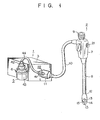
- FIG. 1 shows an endoscope 2 connected to a gas/luquid feeding apparatus housing 1.
- the gas/luquid feeding apparatus housing 1 is integral with, for example, a light source unit.
- a gas feed pump 4 or gas feeding means (Fig. 2), a light source lamp (not shown), etc., are disposed in a casing 3 of the apparatus housing 1, and a liquid feed tank 5 is removably attached to a side plate of the casing 3 by means of a fixing ring 6.
- the main body of the endoscope 2 is formed of an operating section 7 and an insertion section 8.
- the operating section 7 is provided with an eyepiece section 9, and is connected with a universal cord 10.
- the distal end of the universal cord 10 is fitted with a connector 11 which is removably connected to the gas/liquid feeding apparatus housing 1.
- a distal end portion 12 is provided at the distal end of the insertion section 8.
- the distal end portion 12 is provided with illumination windows 13 connected to an illumination optical system, an objective lens 14 connected to an observation optical system, and a discharge port 15 through which gas or liquid is discharged.
- a selector valve 16 is disposed inside the operating section 7 of the main body of the endoscope 2.
- the selector valve 16 is connected to the discharge port 15 by means of a gas/liquid feed passage 17 formed of a synthetic resin tube.
- a gas feed passage 18 and a liquid feed passage 19 each formed of a synthetic resin tube are arranged in the universal cord 10.
- the respective one end portions of the gas feed passage 18 and the liquid feed passage 19 are coupled to the selector valve 16.
- the other end portion of the gas feed passage 18 is connected to a connection port in the distal end face of the connector 11 so that the gas feed passage 18 is connected to the gas feed pump 4 through the connection port when the connector 11 is connected to the gas/liquid feeding apparatus housing 1.
- the other end portion of the liquid feed passage 19 communicates with a liquid inlet port 20 in the connector 11.
- the air feed passage 18 or the liquid feed passage 19 may be caused to selectively communicate with the gas/liquid feed passage 17 by the selector valve 16.
- the selector valve 16 makes a selection between gas and liquid feeding operations when an operating button 21 at the operating section 7 is pushed externally.
- a connected portion 22 is formed on the lateral surface of the connector 11.
- the connected portion 22 constitutes a switching mechanism, and is formed of a cylinder member 23 set in the connector 11 with its screw portion projected outward from the connector 11, a connecting member 24 in the form of a cylinder open at both ends and coaxially screwed on the screw portion of the cylinder member 23 at the rear end opening side, and a cylindrical movable member 25 slidable in the cylinder member 23.
- the cylinder member 23 is in the form of a bottomed cylinder.which has the screw portion on the outer peripheral surface near its open end portion and a projected portion 26 protruding inward from its inner peripheral surface. Inside the connector 11, first and second connection ports 27 and 28 protrude outward from the outer peripheral surface of the cylinder member 23.
- connection ports 27 and 28 have their respective communication holes opening into the cylinder member 23.
- the first connection port 27 is connected with a forked gas feed passage (communicating meang) 29 communicating with the gas feed passage 18, while the second connection port 28 is connected with the liquid inlet port 20 of the liquid feed passage 19, From the inner peripheral surface of the connecting member 24 at the front end opening portion thereof protrudes a ring-shaped retaining portion 32 which retains a C-ring (Fig. 4) of an insertion member (connecting portion) 30 mentioned later.
- a circular bore portion 33 extending to the rear end side is formed in the center of the front end face of the movable member 25.
- a communication hole 34 is formed, opening into the bore portion 33.
- 0-rings 35 and 36 are fitted on those portions of the outer peripheral surface of the thick middle portion of the movable member 25 which lie before and behind the communication hole 34, respectively.
- the 0-rings 35 and 36 prevent liquid from leaking into the communication hole 34.
- Narrow portions 37 and 38 are formed in front of the O-ring 35 and at the back of the 0-ring 36, respectively.
- the outside diameter of the front narrow portion 37 is substantially smaller than the inside diameter of the projected portion 26 of the cylinder member 23 so that an annular gap is-formed between the narrow portion 37 and the projected portion 26.
- An O-ring 39 is fitted on the outer peripheral surface of the narrow portion 37 at its front end portion.
- the rear narrow portion 38 is fitted with one end of a compression coil spring 40 in the cylinder member 23.
- the movable member 25 is urged forward by the urging force of the coil spring 40, and is normally held in a projected position or forward position where the thick middle portion is caught by the projected portion 26, as shown in Fig. 3.
- the liquid feed passage 19 is connected to the forked gas feed passage 29 through the second connection port 28, a space between the cylinder member 23 and the rear narrow portion 38 of the movable member 25, and the first connection port 27.
- the movable member 25 moves as a mouthpiece 41 (mentioned later) is attached or detached.
- the liquid feed tank 5, whose top opening portion is closed by a cover 42, is composed of a closed container 43 containing therein a liquid such as water or a medical fluid.
- the cover 42 is fitted with the proximal end portion of a coupling tube 44.
- the coupling tube 44 has a double-tube structure, consisting of a thick gas feed tube 45 and a narrow liquid feed tube 46 therein. As shown in Fig. 2, the respective proximal end portions of the air feed tube 45 and the liquid feed tube 46 penetrate the cover 42 to be inserted into the closed container 43.
- the open ends of the gas feed tube 45 and the liquid feed tube 46 are held at the upper and lower portions, respectively, of the interior of the closed container 43.
- the aforementioned cylindrical mouthpiece 41 open at both ends is attached at one opening portion to the distal end portion of the coupling tube 44.
- the insertion member 30 is coaxially screwed in the other opening portion of the mouthpiece 41.
- the insertion member 30 is integrally formed of a thick air feed mouthpiece 47 and a narrow liquid feed mouthpiece 48 coaxially disposed in the gas feed mouthpiece 47.
- a plurality of axially extending communication holes are formed between the air feed mouthpiece 47 and the liquid feed mouthpiece 48.
- the distal end portion of the gas feed tube 45 is attached to the front portion of the gas feed mouthpiece 47, while the distal end portion of the liquid feed tube 46 is attached to the front portion of the liquid feed mouthpiece 48.
- the C-ring 31 and an O-ring 49 are fitted on the outer peripheral surface of the gas feed mouthpiece 47. If the mouthpiece 41 is connected to the connected portion 22 of the connector 11, the movable member 25 is pushed in against the urging force of the coil spring 40 by a stepped portion formed on the inner peripheral surface of the liquid feed mouthpiece 48 at the rear portion thereof. When the movable member 25 moves to the depressed position where the C-ring 31 of the gas feed mouthpiece 47 is. caught by the retaining portion 32 of the connecting member 24, the communication hole of the second connection port 28 aligns with the communication hole 34 of the movable member 25.
- the liquid feed passage 19 is allowed to communicate with the liquid feed tube 46 by means of the second connection port 28, the communication hole 34, the bore portion 33, and the liquid feed mouthpiece 48.
- the forked gas feed passage 29 is allowed to communicate with the gas feed tube 45 by means of the first connection port 27, an annular space between the front narrow portion 37 of the movable member 25 and the cylinder member 23, an annular gap between the front narrow portion 37 and the projected portion 26 of the cylinder member 23, the interior of the connecting member 24, and the gas feed mouthpiece 47.
- the connector 11 of the endoscope 2 is connected to the gas/liquid feeding apparatus housing I, and the mouthpiece 41 of the coupling tube 44 is connected to the connected portion 22 of the connector 11, as shown in Fig. 1.
- the gas feed passage 18 of the connector 11 is connected to the air feed pump 4.
- the mouthpiece 41 is connected to the connected portion 22 of the connector 11, the liquid feed passage 19 and the forked gas feed passage 29 are connected to the liquid feed tube 46 and the gas feed tube 45, respectively, as shown in Fig. 4.
- the movable member 25 is pushed back to the projected position shown in Fig. 3 by the urging force of the coil spring 40.
- the communication hole 34 of the movable member 25 is blocked by the cylinder wall of the cylinder member 23, and the water or medical fluid remaining in the liquid feed passage 19 and the gas/liquid feed passage 17 can be discharged to the outside through the discharge port 15 at the end of the liquid feeding operation.
- a projected portion 52 coaxially protrudes from the bottom portion of a cylinder member 51 of a connected portion 22, constituting.a switching mechanism, into the cylinder member 51.
- a valve plug 53 in the form of a truncated cone is formed at the extreme end of the projected portion 52.
- a valve seat 55 corresponding in shape to the valve plug 53 is formed at the bottom portion of a movable member 54 which is in the form of a bottomed cylinder axially movable within the cylinder member 51.
- the movable member 54 has such an outside diameter that an annular space is defined between its outer peripheral surface and the inner peripheral surface of the cylinder member 51.
- An O-ring 56 is fitted on the outer peripheral surface of the movable member 54 on the valve seat side so as to seal the annular space.
- Another O-ring 58 is. fitted on the opening-side portion of the outer peripheral surface of the movable member 54.
- a compression coil spring 59 is fitted in the cylinder member 51 on the valve seat side of the movable member 54. The movable member 54 is normally held by the urging force of the coil spring 59 in a projected position or forward position where the valve seat 55 is pressed against the valve plug 53 of the cylinder member 51 to close the valve, as shown in F ig. 5.
- a liquid feed passage 19 communicates with a forked gas feed passage 29 by means of a second connection port 28, a space inside the cylinder member 51, and a first connection port 27.
- the liquid feed passage 19 is allowed to communicate with a liquid feed tube 46 by means of the inside space of the cylinder member 51, a gap between the valve seat 55 and the projected portion 52, the interior of the movable member 54, and the liquid feed mouthpiece 48, while the forked gas feed passage 29 is allowed to communicate with the gas feed tube 45 by means of the first connection port 27, the space between the outer peripheral surface of the movable member 54 and the inner peripheral surface of the cylinder member 51, the interior of the connecting member 24, and the gas feed mouthpiece 47.
- the mouthpiece 41 of the coupling tube 44 is connected to the connected portion 22 of the connector 11, the liquid feed passage 19 is connected to the liquid feed tube 46', and the forked air feed passage 29 is connected to the gas feed tube 45.
- the operating button 21 is pushed to switch the selector valve 16 in this state, compressed air supplied from the gas feed pump 4 is led into the closed container 43 of the liquid feed tank 5 to increase the internal pressure of the closed container 43.
- a liquid such as water, a medical fluid, etc., in the closed container 43 can be fed into the liquid feed passage 19 of the endoscope 2 through the liquid feed tube 46, and further into the gas/liquid feed passage 17 through the selector valve 16.
- the movable member 54 is pushed back to.the projected position shown in Fig. 5 by the urging force of the coil spring 59.
- the valve seat 55 of the movable member 54 is pressed against the valve plug 53 of the cylinder member 51 to stop the spece between the valve seat 55 and the valve plug 53, and the liquid feed passage 19 is connected to the forked gas feed passage 29.
- the compressed air supplied from the gas feed pump 4 can be led into the liquid feed passage 19 through the gas feed passage 18, the forked gas feed passage 29, and the interior of the cylinder member 51, and the water or medical fluid remaining in the liquid feed passage 19 and the gas/liquid feed passage 17 can be discharged to the outside through the discharge port 15 at the end of the liquid feeding operation.
- a switching mechanism which operates as a liquid feed tube to lead out a liquid in a liquid feed tank, is connected or disconnected. If the liquid feed tube is connected, a liquid feed passage in an apparatus housing is allowed to communicate with the liquid feed tube of the liquid feed tank, and a gas feed passage in the apparatus housing is allowed to communicate with an air feed tube. If the liquid feed tube is disconnected, on the other hand, the liquid feed passage in the apparatus housing is connected to the gas feed tube.
- the switching operation of the switching mechanism is performed in conjunction with the attachment or detachment of the liquid feed tube, there is no possibility of incorrect operation, and safety performance is improved. Moreover, the liquid feed passage in the apparatus housing is cut off from the outside when the liquid feed tube is removed, so that there is no fear of any foreign substances entering the liquid feed passage.
Abstract
Description
- This invention relates to an endoscope in which a gas feed passage and a liquid feed passage to carry gas and liquid are formed in the main body.
- In some endoscopes, a liquid feed passage is formed internally, a liquid inlet of the liquid feed passage is formed in a connector attached to a forward end of a universal cord and a liquid outlet is formed in the distal end portion of the endoscope. Supplied through the liquid feed passage, a medical fluid may be sprayed in a body cavity, or water may be used to clean the outer surface of an objective lens. When using the endoscopes of this type for liquid feeding operation, the liquid would remain in the liquid feed passage after use if the use of the endoscope is suspended under a liquid feeding condition. In this case, if the liquid remaining in the liquid feed passage is left as it is, it could spoil or become contaminated by germs, etc. Thus, if the endoscope is used again with the-liquid still remaining in the liquid feed passage, B-type hepatitis or hospital infection may be caused.
- Accordingly, there is conventionally proposed an improved endoscope as stated in Japanese Patent Disclosure No. 166794/79. In this endoscope, an air feed passage and a water feed passage are formed internally, and an air/water feed selector valve mechanism is provided so that the air or water feeding operation may be selected by switching an air/water selector valve. Also, an operating valve mechanism is used to feed compressed air into the water feed passage, thereby removing water from the water feed passage. In the endoscope of this construction, however, both the air/water feed selector valve mechanism and the operating valve mechanism require a manual valve switching operation by an operator. Thus, the operation is complicated and troublesome, and it is hard to judge whether the valves are in a water feeding state or whether they are in a draining state. Such a situation could easily lead to incorrect operation and would be hazardous.
- The object of this invention is to provide an endoscope capable of readily and securely discharging water, a medical fluid, or some other liquid remaining in a liquid feed passage after the completion of a liquid feeding operation, as well as of reducing the possibility of incorrect operation in order to improve safety performance.
- This invention can be more fully understood from the following detailed description when taken in conjunction with the accompanying drawings, in which:
- Figs. 1 to 4 show an endoscope according to one embodiment of this invention, in which Fig. 1 is a general perspective view showing an operating state,
- Fig. 2 is a schematic view showing the connection between a gas feed pump and a liquid feed pump for purposes of illustrating a liquid feeding operation,
- Fig. 3 is a sectional view of a connected portion, and
- Fig. 4 is a sectional view showing a connecting portion and the connected portions connected to each other; and
- Figs. 5 and 6 show an endoscope according to another embodiment of the invention, Fig. 5 is a sectional view of a connected portion, and Fig. 6 is a sectional view showing a connecting portion and the connected portions connected to each other.
- Referring now to Figs. 1 to 4, one embodiment of this invention will be described in detail. Fig. 1 shows an
endoscope 2 connected to a gas/luquidfeeding apparatus housing 1. The gas/luquidfeeding apparatus housing 1 is integral with, for example, a light source unit. A gas feed pump 4 or gas feeding means (Fig. 2), a light source lamp (not shown), etc., are disposed in acasing 3 of theapparatus housing 1, and aliquid feed tank 5 is removably attached to a side plate of thecasing 3 by means of afixing ring 6. The main body of theendoscope 2 is formed of anoperating section 7 and aninsertion section 8. Theoperating section 7 is provided with aneyepiece section 9, and is connected with auniversal cord 10. The distal end of theuniversal cord 10 is fitted with aconnector 11 which is removably connected to the gas/liquidfeeding apparatus housing 1. Adistal end portion 12 is provided at the distal end of theinsertion section 8. Thedistal end portion 12 is provided withillumination windows 13 connected to an illumination optical system, anobjective lens 14 connected to an observation optical system, and adischarge port 15 through which gas or liquid is discharged. As shown in Fig. 2, moreover, aselector valve 16 is disposed inside theoperating section 7 of the main body of theendoscope 2. Theselector valve 16 is connected to thedischarge port 15 by means of a gas/liquid feed passage 17 formed of a synthetic resin tube. Agas feed passage 18 and aliquid feed passage 19 each formed of a synthetic resin tube are arranged in theuniversal cord 10. The respective one end portions of thegas feed passage 18 and theliquid feed passage 19 are coupled to theselector valve 16. The other end portion of thegas feed passage 18 is connected to a connection port in the distal end face of theconnector 11 so that thegas feed passage 18 is connected to the gas feed pump 4 through the connection port when theconnector 11 is connected to the gas/liquidfeeding apparatus housing 1. The other end portion of theliquid feed passage 19 communicates with aliquid inlet port 20 in theconnector 11. Thus, theair feed passage 18 or theliquid feed passage 19 may be caused to selectively communicate with the gas/liquid feed passage 17 by theselector valve 16. Theselector valve 16 makes a selection between gas and liquid feeding operations when anoperating button 21 at theoperating section 7 is pushed externally. A connectedportion 22 is formed on the lateral surface of theconnector 11. The connectedportion 22 constitutes a switching mechanism, and is formed of acylinder member 23 set in theconnector 11 with its screw portion projected outward from theconnector 11, a connectingmember 24 in the form of a cylinder open at both ends and coaxially screwed on the screw portion of thecylinder member 23 at the rear end opening side, and a cylindrical movable member 25 slidable in thecylinder member 23. Thecylinder member 23 is in the form of a bottomed cylinder.which has the screw portion on the outer peripheral surface near its open end portion and a projectedportion 26 protruding inward from its inner peripheral surface. Inside theconnector 11, first andsecond connection ports cylinder member 23. Theconnection ports cylinder member 23. Thefirst connection port 27 is connected with a forked gas feed passage (communicating meang) 29 communicating with thegas feed passage 18, while thesecond connection port 28 is connected with theliquid inlet port 20 of theliquid feed passage 19, From the inner peripheral surface of the connectingmember 24 at the front end opening portion thereof protrudes a ring-shaped retaining portion 32 which retains a C-ring (Fig. 4) of an insertion member (connecting portion) 30 mentioned later. - A
circular bore portion 33 extending to the rear end side is formed in the center of the front end face of the movable member 25. In the outer peripheral surface of the movable member 25 a communication hole 34 is formed, opening into thebore portion 33. 0-rings rings Narrow portions ring 35 and at the back of the 0-ring 36, respectively. The outside diameter of the frontnarrow portion 37 is substantially smaller than the inside diameter of the projectedportion 26 of thecylinder member 23 so that an annular gap is-formed between thenarrow portion 37 and the projectedportion 26. An O-ring 39 is fitted on the outer peripheral surface of thenarrow portion 37 at its front end portion. The rearnarrow portion 38 is fitted with one end of acompression coil spring 40 in thecylinder member 23. The movable member 25 is urged forward by the urging force of thecoil spring 40, and is normally held in a projected position or forward position where the thick middle portion is caught by the projectedportion 26, as shown in Fig. 3. In this position, theliquid feed passage 19 is connected to the forkedgas feed passage 29 through thesecond connection port 28, a space between thecylinder member 23 and the rearnarrow portion 38 of the movable member 25, and thefirst connection port 27. In this position, moreover, the movable member 25 moves as a mouthpiece 41 (mentioned later) is attached or detached. - The
liquid feed tank 5, whose top opening portion is closed by acover 42, is composed of a closedcontainer 43 containing therein a liquid such as water or a medical fluid. Thecover 42 is fitted with the proximal end portion of acoupling tube 44. Thecoupling tube 44 has a double-tube structure, consisting of a thickgas feed tube 45 and a narrowliquid feed tube 46 therein. As shown in Fig. 2, the respective proximal end portions of theair feed tube 45 and theliquid feed tube 46 penetrate thecover 42 to be inserted into the closedcontainer 43. The open ends of thegas feed tube 45 and theliquid feed tube 46 are held at the upper and lower portions, respectively, of the interior of the closedcontainer 43. The aforementionedcylindrical mouthpiece 41 open at both ends is attached at one opening portion to the distal end portion of thecoupling tube 44. As shown in Fig. 4, theinsertion member 30 is coaxially screwed in the other opening portion of themouthpiece 41. Theinsertion member 30 is integrally formed of a thickair feed mouthpiece 47 and a narrowliquid feed mouthpiece 48 coaxially disposed in thegas feed mouthpiece 47. A plurality of axially extending communication holes are formed between theair feed mouthpiece 47 and theliquid feed mouthpiece 48. The distal end portion of thegas feed tube 45 is attached to the front portion of thegas feed mouthpiece 47, while the distal end portion of theliquid feed tube 46 is attached to the front portion of theliquid feed mouthpiece 48. The C-ring 31 and an O-ring 49 are fitted on the outer peripheral surface of thegas feed mouthpiece 47. If themouthpiece 41 is connected to the connectedportion 22 of theconnector 11, the movable member 25 is pushed in against the urging force of thecoil spring 40 by a stepped portion formed on the inner peripheral surface of theliquid feed mouthpiece 48 at the rear portion thereof. When the movable member 25 moves to the depressed position where the C-ring 31 of thegas feed mouthpiece 47 is. caught by the retainingportion 32 of the connectingmember 24, the communication hole of thesecond connection port 28 aligns with the communication hole 34 of the movable member 25. At the same time, theliquid feed passage 19 is allowed to communicate with theliquid feed tube 46 by means of thesecond connection port 28, the communication hole 34, thebore portion 33, and theliquid feed mouthpiece 48. Also, the forkedgas feed passage 29 is allowed to communicate with thegas feed tube 45 by means of thefirst connection port 27, an annular space between the frontnarrow portion 37 of the movable member 25 and thecylinder member 23, an annular gap between the frontnarrow portion 37 and the projectedportion 26 of thecylinder member 23, the interior of the connectingmember 24, and thegas feed mouthpiece 47. - In operation, in the arrangementdescribed above, the
connector 11 of theendoscope 2 is connected to the gas/liquid feeding apparatus housing I, and themouthpiece 41 of thecoupling tube 44 is connected to the connectedportion 22 of theconnector 11, as shown in Fig. 1. When theconnector 11 of theendoscope 2 is connected to the gas/liquidfeeding apparatus housing 1, thegas feed passage 18 of theconnector 11 is connected to the air feed pump 4. When themouthpiece 41 is connected to the connectedportion 22 of theconnector 11, theliquid feed passage 19 and the forkedgas feed passage 29 are connected to theliquid feed tube 46 and thegas feed tube 45, respectively, as shown in Fig. 4. In this state, therefore, if theoperating button 21 is pushed in to switch theselector valve 16 thereby blocking thegas feed passage 18, compressed air supplied from the gas feed pump 4 is led from thegas feed passage 18 of theconnector 11 into the forkedgas feed passage 29, and is further fed into theclosed container 43 of theliquid feed tank 5 through thegas feed tube 45 of thecoupling tube 44. Accordingly, the internal pressure of theclosed container 43 increases, so that the water, medical fluid or some other liquid in theclosed container 43 is fed into theliquid feed passage 19 of theendoscope 2 through theliquid feed tube 46, and is further led into the gas/liquid feed passage 17 through theselector valve 16. - If the
mouthpiece 41 of thecoupling tube 44 is removed from theconnector 11 of theendoscope 2 after the liquid feeding operation is completed, the movable member 25 is pushed back to the projected position shown in Fig. 3 by the urging force of thecoil spring 40. Thus, the communication hole 34 of the movable member 25 is blocked by the cylinder wall of thecylinder member 23, and the water or medical fluid remaining in theliquid feed passage 19 and the gas/liquid feed passage 17 can be discharged to the outside through thedischarge port 15 at the end of the liquid feeding operation. - Referring now to Figs. 5 and 6, another embodiment of the invention will be described. In this embodiment, a projected
portion 52 coaxially protrudes from the bottom portion of acylinder member 51 of a connectedportion 22, constituting.a switching mechanism, into thecylinder member 51. Avalve plug 53 in the form of a truncated cone is formed at the extreme end of the projectedportion 52. Avalve seat 55 corresponding in shape to thevalve plug 53 is formed at the bottom portion of amovable member 54 which is in the form of a bottomed cylinder axially movable within thecylinder member 51. Themovable member 54 has such an outside diameter that an annular space is defined between its outer peripheral surface and the inner peripheral surface of thecylinder member 51. An O-ring 56 is fitted on the outer peripheral surface of themovable member 54 on the valve seat side so as to seal the annular space. Another O-ring 58 is. fitted on the opening-side portion of the outer peripheral surface of themovable member 54. Also, acompression coil spring 59 is fitted in thecylinder member 51 on the valve seat side of themovable member 54. Themovable member 54 is normally held by the urging force of thecoil spring 59 in a projected position or forward position where thevalve seat 55 is pressed against thevalve plug 53 of thecylinder member 51 to close the valve, as shown in Fig. 5. In this state, aliquid feed passage 19 communicates with a forkedgas feed passage 29 by means of asecond connection port 28, a space inside thecylinder member 51, and afirst connection port 27. If amouthpiece 41 of acoupling tube 44 is connected to the connectedportion 22 of aconnector 11, themovable member 54 is pushed backward against the urging force of thecoil spring 59 by aliquid feed mouthpiece 48. When themovable member 54 moves to a depressed position where a C-ring 31 of agas feed mouthpiece 47 is caught by a retainingportion 32 of a connectingmember 24, thevalve seat 55 is separated from thevalve plug 53 of thecylinder member 51. Thus, theliquid feed passage 19 is allowed to communicate with aliquid feed tube 46 by means of the inside space of thecylinder member 51, a gap between thevalve seat 55 and the projectedportion 52, the interior of themovable member 54, and theliquid feed mouthpiece 48, while the forkedgas feed passage 29 is allowed to communicate with thegas feed tube 45 by means of thefirst connection port 27, the space between the outer peripheral surface of themovable member 54 and the inner peripheral surface of thecylinder member 51, the interior of the connectingmember 24, and thegas feed mouthpiece 47. - As in the first embodiment, therefore, if the
mouthpiece 41 of thecoupling tube 44 is connected to the connectedportion 22 of theconnector 11, theliquid feed passage 19 is connected to the liquid feed tube 46', and the forkedair feed passage 29 is connected to thegas feed tube 45. Thus, when theoperating button 21 is pushed to switch theselector valve 16 in this state, compressed air supplied from the gas feed pump 4 is led into theclosed container 43 of theliquid feed tank 5 to increase the internal pressure of theclosed container 43. Then, a liquid such as water, a medical fluid, etc., in theclosed container 43 can be fed into theliquid feed passage 19 of theendoscope 2 through theliquid feed tube 46, and further into the gas/liquid feed passage 17 through theselector valve 16. - If the
mouthpiece 41 of thecoupling tube 44 is removed from theconnector 11 of theendoscope 2 after the liquid feeding operation is completed, themovable member 54 is pushed back to.the projected position shown in Fig. 5 by the urging force of thecoil spring 59. As a result, thevalve seat 55 of themovable member 54 is pressed against thevalve plug 53 of thecylinder member 51 to stop the spece between thevalve seat 55 and thevalve plug 53, and theliquid feed passage 19 is connected to the forkedgas feed passage 29. Also in this case, therefore, the compressed air supplied from the gas feed pump 4 can be led into theliquid feed passage 19 through thegas feed passage 18, the forkedgas feed passage 29, and the interior of thecylinder member 51, and the water or medical fluid remaining in theliquid feed passage 19 and the gas/liquid feed passage 17 can be discharged to the outside through thedischarge port 15 at the end of the liquid feeding operation. - This invention is not limited to the aforementioned embodiments. For example, the mechanism for connecting the
mouthpiece 41 of thecoupling tube 44 and the connectedportion 22 of theconnector 11 may be modified as required. It is to be understood, moreover, that various other changes and modifications may be effected by one skilled in the art without departing from the scope or spirit of the invention. - According to this invention, as described above, a switching mechanism, which operates as a liquid feed tube to lead out a liquid in a liquid feed tank, is connected or disconnected. If the liquid feed tube is connected, a liquid feed passage in an apparatus housing is allowed to communicate with the liquid feed tube of the liquid feed tank, and a gas feed passage in the apparatus housing is allowed to communicate with an air feed tube. If the liquid feed tube is disconnected, on the other hand, the liquid feed passage in the apparatus housing is connected to the gas feed tube. Thus, after the liquid feeding operation is completed, water, medical fluid or some other liquid remaining in the liquid feed passage can be securely discharged to the outside with ease. Since the switching operation of the switching mechanism is performed in conjunction with the attachment or detachment of the liquid feed tube, there is no possibility of incorrect operation, and safety performance is improved. Moreover, the liquid feed passage in the apparatus housing is cut off from the outside when the liquid feed tube is removed, so that there is no fear of any foreign substances entering the liquid feed passage.
Claims (7)
Priority Applications (1)
| Application Number | Priority Date | Filing Date | Title |
|---|---|---|---|
| AT82110478T ATE25813T1 (en) | 1981-11-20 | 1982-11-12 | ENDOSCOPE. |
Applications Claiming Priority (2)
| Application Number | Priority Date | Filing Date | Title |
|---|---|---|---|
| JP186246/81 | 1981-11-20 | ||
| JP56186246A JPS5889232A (en) | 1981-11-20 | 1981-11-20 | Endoscope |
Publications (3)
| Publication Number | Publication Date |
|---|---|
| EP0081098A2 true EP0081098A2 (en) | 1983-06-15 |
| EP0081098A3 EP0081098A3 (en) | 1984-07-04 |
| EP0081098B1 EP0081098B1 (en) | 1987-03-11 |
Family
ID=16184901
Family Applications (1)
| Application Number | Title | Priority Date | Filing Date |
|---|---|---|---|
| EP19820110478 Expired EP0081098B1 (en) | 1981-11-20 | 1982-11-12 | Endoscope |
Country Status (5)
| Country | Link |
|---|---|
| US (1) | US4489712A (en) |
| EP (1) | EP0081098B1 (en) |
| JP (1) | JPS5889232A (en) |
| AT (1) | ATE25813T1 (en) |
| DE (1) | DE3275625D1 (en) |
Cited By (1)
| Publication number | Priority date | Publication date | Assignee | Title |
|---|---|---|---|---|
| EP0120454A1 (en) * | 1983-03-22 | 1984-10-03 | Olympus Optical Co., Ltd. | Air and liquid supplying device for endoscope |
Families Citing this family (13)
| Publication number | Priority date | Publication date | Assignee | Title |
|---|---|---|---|---|
| JPS59160431A (en) * | 1983-03-01 | 1984-09-11 | オリンパス光学工業株式会社 | Air and liquid feeding apparatus of endoscope |
| US4736732A (en) * | 1985-09-03 | 1988-04-12 | Olympus Optical Co., Ltd. | Endoscopic fluid changing device |
| US4907744A (en) * | 1988-05-03 | 1990-03-13 | Les Produits Associes Lpa-Broxo S.A. | Oral hygiene device |
| CH676661A5 (en) * | 1988-06-16 | 1991-02-28 | Claude F Dr Rausis | |
| US7597662B2 (en) * | 2004-09-30 | 2009-10-06 | Boston Scientific Scimed, Inc. | Multi-fluid delivery system |
| EP2303100B1 (en) * | 2008-04-16 | 2020-02-12 | United States Endoscopy Group, Inc. | Adaptor for a water bottle of an endoscope |
| CN102686142B (en) * | 2009-08-31 | 2014-10-29 | 布拉蔻诊断公司 | In-line gas adaptor for endoscopic apparatus |
| WO2011032067A1 (en) | 2009-09-14 | 2011-03-17 | Bracco Diagnostics Inc. | In-line gas adaptor for endoscopic apparatus |
| DE102009056108A1 (en) * | 2009-11-30 | 2011-06-01 | Karl Storz Gmbh & Co. Kg | Medical device for supporting an endoscopic examination |
| JP5611637B2 (en) * | 2010-03-31 | 2014-10-22 | 富士フイルム株式会社 | Medical air supply system |
| EP2554198A4 (en) * | 2010-04-02 | 2014-05-07 | Sang Yub Lee | Liquid medicine administering device for endoscopic surgery, medical controller for liquid medicine, and liquid medicine administering device for endoscopic surgery comprising same |
| US8870756B2 (en) | 2010-10-08 | 2014-10-28 | ERBE-USA, Inc. | Hybrid apparatus for fluid supply for endoscopic irrigation and lens cleaning |
| US10456014B2 (en) | 2012-03-30 | 2019-10-29 | United States Endoscopy Group, Inc. | Water bottle cap assemblies for an endoscopic device |
Citations (3)
| Publication number | Priority date | Publication date | Assignee | Title |
|---|---|---|---|---|
| DE2920724A1 (en) * | 1978-05-19 | 1979-11-22 | Olympus Optical Co | DEVICE FOR AN ENDOSCOPE FOR SUPPLYING A MEDIUM |
| US4325362A (en) * | 1978-03-28 | 1982-04-20 | Kabushiki Kaisha Medos Kenkyusho | Endoscope |
| EP0082950A2 (en) * | 1981-11-19 | 1983-07-06 | Olympus Optical Co., Ltd. | Liquid supply device for an endoscope |
Family Cites Families (6)
| Publication number | Priority date | Publication date | Assignee | Title |
|---|---|---|---|---|
| US1821719A (en) * | 1928-08-10 | 1931-09-01 | Messier George Louis Rene Jean | Brake controlling device |
| US3297046A (en) * | 1964-02-04 | 1967-01-10 | Gerity Products Inc | Mixing and diverter valve |
| US3958566A (en) * | 1973-08-27 | 1976-05-25 | Olympus Optical Co., Ltd. | Suction control device for an endoscope |
| US4185663A (en) * | 1977-05-25 | 1980-01-29 | Robertshaw Controls Company | Condition responsive by-pass valve construction |
| US4261343A (en) * | 1978-03-28 | 1981-04-14 | Kabushiki Kaisha Medos Kenkyusho | Endoscope |
| US4281646A (en) * | 1978-06-30 | 1981-08-04 | Olympus Optical Co., Ltd. | Cleaning device for an observation window of an endoscope |
-
1981
- 1981-11-20 JP JP56186246A patent/JPS5889232A/en active Granted
-
1982
- 1982-11-10 US US06/440,579 patent/US4489712A/en not_active Expired - Lifetime
- 1982-11-12 EP EP19820110478 patent/EP0081098B1/en not_active Expired
- 1982-11-12 DE DE8282110478T patent/DE3275625D1/en not_active Expired
- 1982-11-12 AT AT82110478T patent/ATE25813T1/en not_active IP Right Cessation
Patent Citations (3)
| Publication number | Priority date | Publication date | Assignee | Title |
|---|---|---|---|---|
| US4325362A (en) * | 1978-03-28 | 1982-04-20 | Kabushiki Kaisha Medos Kenkyusho | Endoscope |
| DE2920724A1 (en) * | 1978-05-19 | 1979-11-22 | Olympus Optical Co | DEVICE FOR AN ENDOSCOPE FOR SUPPLYING A MEDIUM |
| EP0082950A2 (en) * | 1981-11-19 | 1983-07-06 | Olympus Optical Co., Ltd. | Liquid supply device for an endoscope |
Cited By (2)
| Publication number | Priority date | Publication date | Assignee | Title |
|---|---|---|---|---|
| EP0120454A1 (en) * | 1983-03-22 | 1984-10-03 | Olympus Optical Co., Ltd. | Air and liquid supplying device for endoscope |
| US4548197A (en) * | 1983-03-22 | 1985-10-22 | Olympus Optical Co., Ltd. | Air and liquid supplying device for endoscope |
Also Published As
| Publication number | Publication date |
|---|---|
| EP0081098B1 (en) | 1987-03-11 |
| JPS5889232A (en) | 1983-05-27 |
| ATE25813T1 (en) | 1987-03-15 |
| US4489712A (en) | 1984-12-25 |
| DE3275625D1 (en) | 1987-04-16 |
| JPH0134050B2 (en) | 1989-07-17 |
| EP0081098A3 (en) | 1984-07-04 |
Similar Documents
| Publication | Publication Date | Title |
|---|---|---|
| US4489712A (en) | Endoscope with a gas/liquid switching mechanism | |
| EP0120454B1 (en) | Air and liquid supplying device for endoscope | |
| US4667655A (en) | Endoscope apparatus | |
| EP0082950B1 (en) | Liquid supply device for an endoscope | |
| EP0123817B1 (en) | Air and liquid supplying device for endoscopes | |
| US4800869A (en) | Endoscope | |
| CN100361621C (en) | Balloon control apparatus | |
| US20060135851A1 (en) | Adapter unit for connecting cleaning fluid supply device to endoscopes | |
| US5427144A (en) | Valve means with fluid retraction means | |
| US4576650A (en) | Method of cleaning endoscope channels | |
| US4550716A (en) | Liquid supplying device for endoscope | |
| US5674183A (en) | Fiberscopes and spray modules | |
| JPH05300871A (en) | Inner/outer communicating device for endoscope | |
| JPH0242491B2 (en) | ||
| JPH0580896B2 (en) | ||
| JP2006280536A (en) | Endoscope | |
| JPH02159244A (en) | Endoscopic apparatus | |
| JPS6320135B2 (en) | ||
| JPH012620A (en) | Endoscope | |
| JPH064059B2 (en) | Switching valve device for endoscope | |
| JP2000170226A (en) | Composite discharge faucet with built-in filter | |
| CN112449578A (en) | Sterilization adapter | |
| JPH01280437A (en) | Liquid feeder for endoscope | |
| JP2547469B2 (en) | Gas / water supply switching device for endoscopes | |
| JP2000287917A (en) | Feed air/water valve structure of endoscope |
Legal Events
| Date | Code | Title | Description |
|---|---|---|---|
| PUAI | Public reference made under article 153(3) epc to a published international application that has entered the european phase |
Free format text: ORIGINAL CODE: 0009012 |
|
| AK | Designated contracting states |
Designated state(s): AT BE CH DE FR GB IT LI NL SE |
|
| PUAL | Search report despatched |
Free format text: ORIGINAL CODE: 0009013 |
|
| AK | Designated contracting states |
Designated state(s): AT BE CH DE FR GB IT LI NL SE |
|
| 17P | Request for examination filed |
Effective date: 19840726 |
|
| GRAA | (expected) grant |
Free format text: ORIGINAL CODE: 0009210 |
|
| AK | Designated contracting states |
Kind code of ref document: B1 Designated state(s): AT BE CH DE FR GB IT LI NL SE |
|
| PG25 | Lapsed in a contracting state [announced via postgrant information from national office to epo] |
Ref country code: SE Effective date: 19870311 Ref country code: NL Effective date: 19870311 Ref country code: LI Effective date: 19870311 Ref country code: IT Free format text: LAPSE BECAUSE OF FAILURE TO SUBMIT A TRANSLATION OF THE DESCRIPTION OR TO PAY THE FEE WITHIN THE PRESCRIBED TIME-LIMIT;WARNING: LAPSES OF ITALIAN PATENTS WITH EFFECTIVE DATE BEFORE 2007 MAY HAVE OCCURRED AT ANY TIME BEFORE 2007. THE CORRECT EFFECTIVE DATE MAY BE DIFFERENT FROM THE ONE RECORDED. Effective date: 19870311 Ref country code: FR Free format text: THE PATENT HAS BEEN ANNULLED BY A DECISION OF A NATIONAL AUTHORITY Effective date: 19870311 Ref country code: CH Effective date: 19870311 Ref country code: BE Effective date: 19870311 Ref country code: AT Effective date: 19870311 |
|
| REF | Corresponds to: |
Ref document number: 25813 Country of ref document: AT Date of ref document: 19870315 Kind code of ref document: T |
|
| REF | Corresponds to: |
Ref document number: 3275625 Country of ref document: DE Date of ref document: 19870416 |
|
| REG | Reference to a national code |
Ref country code: CH Ref legal event code: PL |
|
| EN | Fr: translation not filed | ||
| NLV1 | Nl: lapsed or annulled due to failure to fulfill the requirements of art. 29p and 29m of the patents act | ||
| PLBE | No opposition filed within time limit |
Free format text: ORIGINAL CODE: 0009261 |
|
| STAA | Information on the status of an ep patent application or granted ep patent |
Free format text: STATUS: NO OPPOSITION FILED WITHIN TIME LIMIT |
|
| 26N | No opposition filed | ||
| GBPC | Gb: european patent ceased through non-payment of renewal fee | ||
| PG25 | Lapsed in a contracting state [announced via postgrant information from national office to epo] |
Ref country code: GB Effective date: 19881122 |
|
| PGFP | Annual fee paid to national office [announced via postgrant information from national office to epo] |
Ref country code: DE Payment date: 19961115 Year of fee payment: 15 |
|
| PG25 | Lapsed in a contracting state [announced via postgrant information from national office to epo] |
Ref country code: DE Free format text: LAPSE BECAUSE OF NON-PAYMENT OF DUE FEES Effective date: 19980801 |