EP0081348A2 - Optical cursor control device - Google Patents
Optical cursor control device Download PDFInfo
- Publication number
- EP0081348A2 EP0081348A2 EP82306436A EP82306436A EP0081348A2 EP 0081348 A2 EP0081348 A2 EP 0081348A2 EP 82306436 A EP82306436 A EP 82306436A EP 82306436 A EP82306436 A EP 82306436A EP 0081348 A2 EP0081348 A2 EP 0081348A2
- Authority
- EP
- European Patent Office
- Prior art keywords
- grid
- optical
- control device
- cursor control
- grid pattern
- Prior art date
- Legal status (The legal status is an assumption and is not a legal conclusion. Google has not performed a legal analysis and makes no representation as to the accuracy of the status listed.)
- Granted
Links
Images


Classifications
-
- G—PHYSICS
- G06—COMPUTING; CALCULATING OR COUNTING
- G06F—ELECTRIC DIGITAL DATA PROCESSING
- G06F3/00—Input arrangements for transferring data to be processed into a form capable of being handled by the computer; Output arrangements for transferring data from processing unit to output unit, e.g. interface arrangements
- G06F3/01—Input arrangements or combined input and output arrangements for interaction between user and computer
- G06F3/03—Arrangements for converting the position or the displacement of a member into a coded form
- G06F3/0304—Detection arrangements using opto-electronic means
- G06F3/0317—Detection arrangements using opto-electronic means in co-operation with a patterned surface, e.g. absolute position or relative movement detection for an optical mouse or pen positioned with respect to a coded surface
-
- G—PHYSICS
- G06—COMPUTING; CALCULATING OR COUNTING
- G06F—ELECTRIC DIGITAL DATA PROCESSING
- G06F3/00—Input arrangements for transferring data to be processed into a form capable of being handled by the computer; Output arrangements for transferring data from processing unit to output unit, e.g. interface arrangements
- G06F3/01—Input arrangements or combined input and output arrangements for interaction between user and computer
- G06F3/03—Arrangements for converting the position or the displacement of a member into a coded form
- G06F3/033—Pointing devices displaced or positioned by the user, e.g. mice, trackballs, pens or joysticks; Accessories therefor
- G06F3/0354—Pointing devices displaced or positioned by the user, e.g. mice, trackballs, pens or joysticks; Accessories therefor with detection of 2D relative movements between the device, or an operating part thereof, and a plane or surface, e.g. 2D mice, trackballs, pens or pucks
- G06F3/03543—Mice or pucks
Definitions
- This invention relates to optical cursor control devices and in particular to such cursor control devices useful in interactive, display oriented computer systems wherein a display cursor is movable about the screen of the device by means of the cursor control device.
- the mouse in particular, has become one of the most popular of the pointing devices used with interactive, display oriented computer systems, to control the visual cursor on the system display.
- the mouse tracks the movement of a user's hand as the user moves the mouse about on a work surface or pad usually next to the user's keyboard input to the system.
- Microswitches may be positioned on the top surface of the housing of the mouse to perform various functions in the system upon finger operation of a microswitch selected by the user.
- the mouse has recently become available in the office products market as a part of the 8010 Professional Workstation, developed, manufactured and distributed by Xerox Corporation.
- mice While these mice have proved to be quite useful in performing display functions, they have not been outstandingly reliable, particularly over long periods of use.
- the mechanical moving parts of the mouse such as the balls and wheels, become dirty and slip on the work surface or pad, rather than provide continuous rolling action, or the commutators become dirty and skip.
- the goal is to design a mouse with no moving parts (excluding the microswitches) thereby eliminating the above mentioned mechanical dissatis and providing a mouse with high reliability over long periods of time.
- One direction toward the goal of no moving parts is optics and optical detection of mouse tracking functions.
- the concept of optical tracking i.e., optical detection of an optical image, such as a track, lines, bars or grating, is not new. Examples of such tracking utilizing one or more optical detectors are disclosed in U.S. Patents 3,496,364; 3,524,067; 4,114,034 and 4,180,704.
- optical tracking devices disclose optical tracking techniques suitable to perform the functions required in a mouse, i.e., they are not “smart" enough to provide multidirectional tracking indicative of direction of movement and the amount of that movement necessary for a display oriented computer system.
- an optical cursor control device for use with an interactive, display oriented computer system to provide movement for a visible cursor from position to position on a display screen of such a system.
- the cursor control device provides an output indicative of the amount and direction of movement of the device relative to an orthogonal coordinate system.
- the device relies on a planar grid pattern comprising orthogonally positioned grid lines of uniform spacing, one line and spacing defining a grid period. Means is provided to illuminate at least a portion of the grid pattern.
- Sensor array means comprising optical transducers are provided for each orthogonal direction. Each optical transducer has an elongated radiation detecting area to receive radiation from an elongated radiation collecting area at the plane of the grid pattern. The length of the radiation collecting area of each transducer is equal to or greater than a grid period and the width of these areas is equal to or narrower than the length of one half of a grid period.
- each transducer pair there is a pair of optical transducers for each orthogonal direction.
- the elongated radiation collecting area of each transducer pair at the plane of the grid pattern being parallel and spatially related by a distance predetermined relative to the grid period, e.g., one quarter of the grid period, whereby the output of each transducer pair is indicative of the direction of the orthogonal coordinate being detected.
- Directional movement is sensed by relative movement of the transducer pairs in a direction transverse to the elongated extent of their radiation detecting areas.
- the electrical output of the optical transducers provides quadrature signals indicative of the amount and direction of movement of the optical mouse relative to the grid pattern and, correspondingly, represent positional changes in the location of a visual cursor on a display screen of an interactive, display oriented computer system.
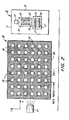
- FIG. 1 illustrates the primary component comprising the optical cursor control device 10 comprising this invention.
- the device 10 includes a source of illumination 12, and a sensor array in the form of two orthogonally positioned optical transducers 14 and 16. These components are assembled in a package and supported in housing 11. Housing 11 is similar to the housing of the electro-mechanical mice now in use and disclosed in Patents 3,541,541 and 3,835,464. These components are optically exposed relative to the bottom surface 13 of the housing 11.
- the bottom surface 13 of the optical cursor control device 10 is moved over the surface of a planar grid pattern 18 in a manner that illumination source 12 illuminates a portion of the grid pattern and radiation from the pattern is reflected and detected by the transducers 14 and 16.
- the grid pattern 18 comprises a plurality of orthogonally arranged radiation absorbing lines 19 and alternate reflective spaces 20.
- the grid lines 19 and spaces 20 are of equal width.
- the width of one line 19 and one spacing 20 is one grid period.
- Lines 19 may be, for example, black lines while spaces 20 are white.
- Transducers 14 and 16 have elongated apertures 15 and 17, respectively, that provide rectangular shaped radiation detecting areas.
- the transducers are positioned to be respectively sensitive to motion in orthogonal directions, such as, X and Y Cartesian coordinates.
- transducer 14 is sensitive to movement over the grid pattern 18 in the X direction while transducer 16 is sensitive to movement over the grid pattern 18 in the Y direction. This is because signal modulation of the reflected radiation from the grid pattern will be achieved as a transducer is moved across grid lines transversely relative to the elongated extent of the transducer aperture while little modulation is seen for motion in the orthogonal direction.
- the transducers 14 and 16 may be of conventionally available photodetectors or optical sensors that provide an electrical output proportional to the radiation detected. Examples are silicon p-n junction diodes or Schottky barrier diodes.
- the illumination source 12 may be incandescent, LED or a diode laser. It is not mandatory that there be only one source 12 or that source 12 be housed with the transducer components in the device housing 11.
- the illumination source may be external of the cursor control device as indicated at 12'.
- the source 12' may be positioned in a manner to illuminate either the bottom or the top surface of the grid pattern 18 or may be made integral with a tablet upon which the grid pattern 18 is fixed, e.g., an illumination source embedded in a translucent plate comprising the tablet.
- Figure 1 While the arrangement in Figure 1 is sensitive to movement in either the X or Y coordinates, there is no capability of sensing the direction of motion in a coordinate direction, i.e., whether movement is -X or +X or -Y or +Y.
- Directional coordinate sensing can be achieved by employing pairs of transducers for each coordinate direction. This arrangement is illustrated in Figure 2.
- Figure 2 is the same as Figure 1 except relative to the sensor array means wherein there are pairs of transducers 14 and 14' and 16 and 16' with transducer apertures 15 and 15' and 17 and 17', respectively.
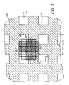
- the radiation collecting areas 22 are four in number and represent the areas of radiation sensing at the plane of the grid pattern 18 as seen by the transducers 14 and 14' and 16 and 16'.
- area 22.1 is the area sensed by transducer 14, area 22.2 by transducer 14', area 22.3 by transducer 16 and area 22.4 by transducer 16'.
- the length of each radiation collecting areas 22 is equal to a grid period or greater in length by an integral number of grid periods and the width of each radiation collecting area 22 is equal to or narrower than the width of a grid line 19 or space 20, i.e., equal to or narrower than one half of a grid period.
- the pairs of radiation collecting areas 22.1 and 22.2 or 22.3 and 22.4 are separated by one quarter of a grid period, as illustrated in Figure 3.
- the X radiation collecting areas 22.1 and 22.2 have a width in the X direction less than or equal to one half a grid period, providing high contrast signal modulation for motion in the X direction, and a height in the X direction equal to or an integral multiple of the grid period, providing no signal modulation for motion in the Y direction.
- the Y radiation collecting areas 22.3 and 22.4 for motion in the Y direction.
- the output of transducers 14 and 14' and 16 and 16' are quadrature signals XA, XB, YA and YB which are employed in the same conventional manner as the quadrature signals produced with the electromechanical mouse available as part of the 8010 Professional Workstation, previously mentioned.
- These four output signals provide quadrature encoding indicative of movement in an X-Y coordinate system.
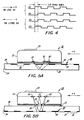
- An example of two of the four signals is shown in Figure 4, which are signals XA and XB.
- the phase relationship of the signal pairs in either the X or Y direction is indicative of the direction of movement.
- the phase relationship shown in Figure 4 is shown to be 90° but obviously this phase difference may be more or less than 90°.
- Each of these signals is a square pulse wave.
- Figure 5 represents several examples of the source/transducer implementation of Figure 2 to perform the cursor control function.
- an optical lens for focusing is not necessary.
- Only arrangements for the Y coordinate direction are illustrated. The arrangements would be the same for the X coordinate direction.
- the preferred illumination source for these arrangements would be a diode laser or LED.
- the grid pattern 18 is formed on the top surface 26 of the transparent tablet 24.
- the bottom surface 28 of tablet 24 is specularly reflective.
- the transducers 16 and 16' and source 12 are disposed in the bottom surface 13 of the housing 11.
- a microswitch 23 is shown at the top of housing 11.
- Cursor control device 10 when moved in the Y direction over the tablet surface 26, will produce the quadrature signals YA and YB.
- the radiation collecting areas 22 of transducers 16 and 16' at the plane of the grid pattern 18 are such that the length of each area is equal to or greater than a grid period and the width of each area is equal to or narrower than one half of a grid period. This is true for all Figure 5 examples.
- the transducers 16 and 16' are disposed on either side of emitter 12.
- the bottom surface 13 of the cursor control device 10 is opaque and provided with apertures 30, 30' and 32.
- the tablet 34 is a diffuse tablet so that radiation entering the tablet through top surface 36 scatters in all directions.
- the bottom surface 38 of tablet 34 is provided with grid pattern 18. Radiation from emitter 12 through aperture 32 is scattered in tablet 34 and absorbed at grid lines 18.
- Transducers 16 and 16' respectively detect scattered light contrast through apertures 30 and 30' in the bottom surface 13.
- apertures 30 and 30' are representative of the radiation detecting apertures 15' and 17' and are of rectangular shape.
- the aperture 32 may be of larger size is dependent on the far field beam of emitter 12. However, the dimensions of aperture 32 are not technically governed by the grid line or space dimensions or the grid period.
- Figure 5C is the same as that of Figure 3B, except that there is only one aperture 33 on the bottom surface 13 of the cursor control device 10 for the illumination source and detection functions.
- the example is similar to the example of Figure 5A except the grid pattern 18 is fixed to the bottom surface 28 of the tablet 24.
- Surface 28 is specularly reflective and'the top tablet surface 26 is transparent
- the radiation collecting areas 22 of transducers 16 and 16' at the plane of grid pattern 18 are designed to have their lengths equal to or greater than a grid period and a width that is equal to or narrower than one half of a grid period.
- Figure 6 illustrates a semiconductor chip that may be employed for the detection tracking functions for each coordinate direction in the implementations illustrated in Figures 2-5.
- the structure comprises the silicon substrate 42 of n-type with a p-type diffused region 46 along its top surface 44. Channels 48 are etched into surface 44 forming a central mesa 50 and side mesas 56.
- An LED or diode laser 52 is mounted on mesa 50 and connected to an appropriate bias circuit.
- Side mesas 56 form p-n junction diodes 54 and 54' functioning as photodetectors.
- Schottky barrier detectors may be employed in lieu of p-n junction detectors.
- doping of these regions should be low to provide low resistance, such as, 20 ohms-cm. Also, a back voltage bias may be applied to detectors 54 and 54' to enhance their sensitivity.
- Figures 7 and 8 illustrate a four detector arrangement that may be employed for the detection tracking functions in the implementations illustrated in Figures 2-5.
- the cursor control device 10 includes an integrated four detector package 50 comprising four transducers 14, 14', 16 and 16'.
- an emitter 12 e.g., an LED.
- a split plastic lens element 54 is molded onto the quad cell package 50 to enhance radiation collection received from the grid pattern tablet 24.
- One portion of the lens element 54 is employed to image the radiation from emitter 12 via lens 56 into a spot at the grid pattern 18 while the other portions of the element, i.e., lenses 58, image radiation collecting areas 22 at the grid pattern 18 onto the transducers 14 and 14'.
- the advantage of the integrated package 50 is that its dimensions and alignment sensitivities are very coarse and can be easily fabricated as a component for an optical mouse that is rugged in construction, reliable and cost effective.
- the radiation collecting areas sensed by each transducer are rectangular in shape and have a length in the direction orthogonal to the coordinate direction being tracked equal to or an integral multiple of the grid period of the grid pattern 18.
- the width of the sensed area in the coordinate direction being tracked is equal to or less than one half of a grid period, so that good signal modulation is achieved as the cursor control device 10, for example, with package 50 is moved relative to grid pattern 18.
- the two coordinate transducers in each of the orthogonal directions have radiation collecting areas at the grid pattern plane that are one quarter of a grid spacing apart to provide in-phase electrical quadrature signals for tracking and monitoring by an interactive, display oriented computer system.
- the implementation of the cursor control device 10 disclosed would be somewhat sensitive to rotational orientation, requiring the user to substantially align and maintain fair alignment of the transducer rectangular apertures (and thus their radiation collecting areas at the grid pattern plane) relative to the orthogonal grid pattern, this is not viewed as a significant user problem since the user would tend to perform such a function unconsciously after little use of the device 10 and, further, the accuracy of such alignment need only be within about ⁇ 20 degrees.
Abstract
Description
- This invention relates to optical cursor control devices and in particular to such cursor control devices useful in interactive, display oriented computer systems wherein a display cursor is movable about the screen of the device by means of the cursor control device.
- Over the past decade or so, different functional control devices for use with computer display systems have been developed along with the rapid development of such systems and so called "smart" display terminals. These devices have taken several forms, such as joy sticks, light pens, touch panels and hand held cursor control devices, commonly referred to as a "mouse". One of the most prevalent uses of these devices is to alter the display at selected locations by controlling a display cursor which is selectively moved over the display by means of the cursor control device.
- The mouse, in particular, has become one of the most popular of the pointing devices used with interactive, display oriented computer systems, to control the visual cursor on the system display. The mouse tracks the movement of a user's hand as the user moves the mouse about on a work surface or pad usually next to the user's keyboard input to the system. Microswitches may be positioned on the top surface of the housing of the mouse to perform various functions in the system upon finger operation of a microswitch selected by the user. The mouse has recently become available in the office products market as a part of the 8010 Professional Workstation, developed, manufactured and distributed by Xerox Corporation.
- Cursor research and development over this period of time has led many to conclude that the concept of the mouse is the preferred and best means for performing cursor function controls, some of the reasons being its adaptability for use in conjunction with a keyboard input of such systems from a human engineering standpoint and ease of display cursor movement with desired functions implemented by microswitches present on the mouse.
- The "mouse" type of cursor control devices employed to date have been of electromechanical design. Examples of such devices may be found in U.S. Patents, 3,304,434; 3,541,541; 3,835,464; 3,892,963 and 3,987,685. The best known electromechanical "grandfather" mouse was developed at Stanford Research Institute and is disclosed in Patent 3,541,541. This mouse employs a pair of wheels that turn potentiometer shafts to encode X and Y motion into analog signals. Each wheel turns as the mouse is moved along its respective coordinate direction and slips sideways as the mouse is moved in an orthogonal direction. When the mouse is moved diagonally, both wheels turn and slip simultaneously. The design of this mouse led to the use of ball bearings as wheels and optical shaft encoders to generate a two bit quadrature signalling code, as dislcosed in Patent 3,892,963. The motion of a wheel caused a two bit output for a coordinate direction to form square waves in quadrature, with phase and frequency determining the direction and speed of travel. Each bit transition represented motion of one resolvable step which was employed to move the cursor on the display screen. Further development led to the employment of a ball or sphere instead of two wheels for more uniform tracking (Patents 3,835,464 and 3,987,685). Internally, the sphere itself was a trackball with shafts turning against the ball and with commutation as shaft encoders or optical disc encoders, the latter being disclosed in Patent 3,304,434.
- While these mice have proved to be quite useful in performing display functions, they have not been outstandingly reliable, particularly over long periods of use. For example, the mechanical moving parts of the mouse, such as the balls and wheels, become dirty and slip on the work surface or pad, rather than provide continuous rolling action, or the commutators become dirty and skip.
- Also, because of the precision and tolerances necessary for the mechanical moving parts and the number of parts involved, these mechanical mice have been expensive to fabricate.
- The goal, therefore, is to design a mouse with no moving parts (excluding the microswitches) thereby eliminating the above mentioned mechanical disavantages and providing a mouse with high reliability over long periods of time. One direction toward the goal of no moving parts is optics and optical detection of mouse tracking functions. The concept of optical tracking, i.e., optical detection of an optical image, such as a track, lines, bars or grating, is not new. Examples of such tracking utilizing one or more optical detectors are disclosed in U.S. Patents 3,496,364; 3,524,067; 4,114,034 and 4,180,704. However, none of these optical tracking devices disclose optical tracking techniques suitable to perform the functions required in a mouse, i.e., they are not "smart" enough to provide multidirectional tracking indicative of direction of movement and the amount of that movement necessary for a display oriented computer system.
- According to this invention, an optical cursor control device or "optical mouse" is disclosed for use with an interactive, display oriented computer system to provide movement for a visible cursor from position to position on a display screen of such a system. The cursor control device provides an output indicative of the amount and direction of movement of the device relative to an orthogonal coordinate system. The device relies on a planar grid pattern comprising orthogonally positioned grid lines of uniform spacing, one line and spacing defining a grid period. Means is provided to illuminate at least a portion of the grid pattern. Sensor array means comprising optical transducers are provided for each orthogonal direction. Each optical transducer has an elongated radiation detecting area to receive radiation from an elongated radiation collecting area at the plane of the grid pattern. The length of the radiation collecting area of each transducer is equal to or greater than a grid period and the width of these areas is equal to or narrower than the length of one half of a grid period.
- In a preferred embodiment, there is a pair of optical transducers for each orthogonal direction. The elongated radiation collecting area of each transducer pair at the plane of the grid pattern being parallel and spatially related by a distance predetermined relative to the grid period, e.g., one quarter of the grid period, whereby the output of each transducer pair is indicative of the direction of the orthogonal coordinate being detected. Directional movement is sensed by relative movement of the transducer pairs in a direction transverse to the elongated extent of their radiation detecting areas.
- The electrical output of the optical transducers provides quadrature signals indicative of the amount and direction of movement of the optical mouse relative to the grid pattern and, correspondingly, represent positional changes in the location of a visual cursor on a display screen of an interactive, display oriented computer system.
- In order that the invention may be more readily understood, reference will now be made to the accompanying drawings, in which:-
- Figure 1 is a schematic view of a planar grid pattern and an optical cursor control device having orthogonal transducers and illumination means in accordance with this invention;
- Figure 2 is a schematic view of a planar grid pattern and an optical cursor control device having pairs of orthogonal transducers and illumination means in accordance with this invention;
- Figure 3 is an enlarged view of a section of the planar grid pattern illustrating the radiation collecting area of the transducer pairs of Figure 2 as superimposed on the grid pattern;
- Figure 4 is a pulse train representation of quadrature signal output of a pair of coordinate transducers of Figure 2, indicative of the direction of motion along a particular orthogonal coordinate;
- Figure 5 illustrates four possible configurations for the cursor control device of this invention employing the implementation of Figure 2;
- Figure 6 illustates an embodiment comprising an integrated semiconductor emitter/detector device that may be employed in the cursor control device of this invention;
- Figures 7 and 8 illustrate another embodiment comprising an emitter/detector device that may be employed as an integrated package in the cursor control device of this invention, Figure 7 illustrating a schematic plan view of the package and Figure 8 illustrating a schematic side view of the package.
- Figure 1 illustrates the primary component comprising the optical
cursor control device 10 comprising this invention. Thedevice 10 includes a source ofillumination 12, and a sensor array in the form of two orthogonally positionedoptical transducers housing 11.Housing 11 is similar to the housing of the electro-mechanical mice now in use and disclosed in Patents 3,541,541 and 3,835,464. These components are optically exposed relative to thebottom surface 13 of thehousing 11. Thebottom surface 13 of the opticalcursor control device 10 is moved over the surface of aplanar grid pattern 18 in a manner thatillumination source 12 illuminates a portion of the grid pattern and radiation from the pattern is reflected and detected by thetransducers - The
grid pattern 18 comprises a plurality of orthogonally arrangedradiation absorbing lines 19 and alternatereflective spaces 20. Thegrid lines 19 andspaces 20 are of equal width. The width of oneline 19 and one spacing 20 is one grid period.Lines 19 may be, for example, black lines whilespaces 20 are white. -
Transducers elongated apertures transducer 14 is sensitive to movement over thegrid pattern 18 in the X direction whiletransducer 16 is sensitive to movement over thegrid pattern 18 in the Y direction. This is because signal modulation of the reflected radiation from the grid pattern will be achieved as a transducer is moved across grid lines transversely relative to the elongated extent of the transducer aperture while little modulation is seen for motion in the orthogonal direction. - The
transducers illumination source 12 may be incandescent, LED or a diode laser. It is not mandatory that there be only onesource 12 or thatsource 12 be housed with the transducer components in thedevice housing 11. The illumination source may be external of the cursor control device as indicated at 12'. The source 12' may be positioned in a manner to illuminate either the bottom or the top surface of thegrid pattern 18 or may be made integral with a tablet upon which thegrid pattern 18 is fixed, e.g., an illumination source embedded in a translucent plate comprising the tablet. - While the arrangement in Figure 1 is sensitive to movement in either the X or Y coordinates, there is no capability of sensing the direction of motion in a coordinate direction, i.e., whether movement is -X or +X or -Y or +Y. Directional coordinate sensing can be achieved by employing pairs of transducers for each coordinate direction. This arrangement is illustrated in Figure 2. Figure 2 is the same as Figure 1 except relative to the sensor array means wherein there are pairs of
transducers transducer apertures - A common feature of the arrangements of both Figures 1 and 2 is that the radiation collecting areas of each of the transducers, as seen by the transducers at the plane of the
grid pattern 18, is oblong or rectangular in shape and the length and width of these areas have a definite relationship with grid period. This relationship is illustrated in Figure 3 for the transducer implementation of Figure 2. - The
radiation collecting areas 22 are four in number and represent the areas of radiation sensing at the plane of thegrid pattern 18 as seen by thetransducers transducer 14, area 22.2 by transducer 14', area 22.3 bytransducer 16 and area 22.4 by transducer 16'. In all cases, the length of eachradiation collecting areas 22 is equal to a grid period or greater in length by an integral number of grid periods and the width of eachradiation collecting area 22 is equal to or narrower than the width of agrid line 19 orspace 20, i.e., equal to or narrower than one half of a grid period. The pairs of radiation collecting areas 22.1 and 22.2 or 22.3 and 22.4 are separated by one quarter of a grid period, as illustrated in Figure 3. For sensing motion in the X direction, the X radiation collecting areas 22.1 and 22.2 have a width in the X direction less than or equal to one half a grid period, providing high contrast signal modulation for motion in the X direction, and a height in the X direction equal to or an integral multiple of the grid period, providing no signal modulation for motion in the Y direction. The same, of course, is true relative to the Y radiation collecting areas 22.3 and 22.4 for motion in the Y direction. - The output of
transducers - If signal XB from
transducer 14 lags signal XA from transducer 14', then motion is in the +X direction. If signal XB leads signal XA, then motion is in the -X direction. By the same token, if the pulse train signal YA fromtransducer 16 is leading in time, the pulse train signal YB from transducer 16' movement is + Y. If YB is leading YA, movement is -Y. - Figure 5 represents several examples of the source/transducer implementation of Figure 2 to perform the cursor control function. In these implementations, an optical lens for focusing is not necessary. For purposes of simplicity, only arrangements for the Y coordinate direction are illustrated. The arrangements would be the same for the X coordinate direction. The preferred illumination source for these arrangements would be a diode laser or LED.
- In Figure 5A the
grid pattern 18 is formed on thetop surface 26 of thetransparent tablet 24. Thebottom surface 28 oftablet 24 is specularly reflective. Thetransducers 16 and 16' andsource 12 are disposed in thebottom surface 13 of thehousing 11. Amicroswitch 23 is shown at the top ofhousing 11.Cursor control device 10, when moved in the Y direction over thetablet surface 26, will produce the quadrature signals YA and YB. Theradiation collecting areas 22 oftransducers 16 and 16' at the plane of thegrid pattern 18 are such that the length of each area is equal to or greater than a grid period and the width of each area is equal to or narrower than one half of a grid period. This is true for all Figure 5 examples. - In Figure 5B, the
transducers 16 and 16' are disposed on either side ofemitter 12. Thebottom surface 13 of thecursor control device 10 is opaque and provided withapertures tablet 34 is a diffuse tablet so that radiation entering the tablet throughtop surface 36 scatters in all directions. Thebottom surface 38 oftablet 34 is provided withgrid pattern 18. Radiation fromemitter 12 throughaperture 32 is scattered intablet 34 and absorbed at grid lines 18.Transducers 16 and 16' respectively detect scattered light contrast throughapertures 30 and 30' in thebottom surface 13. To be noted is thatapertures 30 and 30' are representative of the radiation detecting apertures 15' and 17' and are of rectangular shape. Theaperture 32 may be of larger size is dependent on the far field beam ofemitter 12. However, the dimensions ofaperture 32 are not technically governed by the grid line or space dimensions or the grid period. - The example of Figure 5C is the same as that of Figure 3B, except that there is only one
aperture 33 on thebottom surface 13 of thecursor control device 10 for the illumination source and detection functions. - In Figure 5D the example is similar to the example of Figure 5A except the
grid pattern 18 is fixed to thebottom surface 28 of thetablet 24.Surface 28 is specularly reflective and'thetop tablet surface 26 is transparent Theradiation collecting areas 22 oftransducers 16 and 16' at the plane ofgrid pattern 18 are designed to have their lengths equal to or greater than a grid period and a width that is equal to or narrower than one half of a grid period. - Figure 6 illustrates a semiconductor chip that may be employed for the detection tracking functions for each coordinate direction in the implementations illustrated in Figures 2-5.. The structure comprises the
silicon substrate 42 of n-type with a p-type diffusedregion 46 along itstop surface 44.Channels 48 are etched intosurface 44 forming acentral mesa 50 and side mesas 56. An LED ordiode laser 52 is mounted onmesa 50 and connected to an appropriate bias circuit. Side mesas 56 formp-n junction diodes 54 and 54' functioning as photodetectors. Schottky barrier detectors may be employed in lieu of p-n junction detectors. - In order to achieve large radiation collection areas for the
detectors 54 and 54', doping of these regions should be low to provide low resistance, such as, 20 ohms-cm. Also, a back voltage bias may be applied todetectors 54 and 54' to enhance their sensitivity. - Figures 7 and 8 illustrate a four detector arrangement that may be employed for the detection tracking functions in the implementations illustrated in Figures 2-5. As shown in Figure 7, the
cursor control device 10 includes an integrated fourdetector package 50 comprising fourtransducers detector 50 is anemitter 12, e.g., an LED. As shown in Figure 8, a splitplastic lens element 54 is molded onto thequad cell package 50 to enhance radiation collection received from thegrid pattern tablet 24. One portion of thelens element 54 is employed to image the radiation fromemitter 12 vialens 56 into a spot at thegrid pattern 18 while the other portions of the element, i.e.,lenses 58, imageradiation collecting areas 22 at thegrid pattern 18 onto thetransducers 14 and 14'. There are also two orthogonally positionedlenses 58 fortransducers 16 and 16'. By employing a moldedquad lens element 54 integrated withpackage 50, a small spot of radiation can be obtained. If thegrid pattern 18 ontablet 24 has a grid period of high spatial frequency, relative movement betweenpackage 50 as housed indevice 10 andtablet 24 will produce quadrature signals of high modulation frequency. - The advantage of the
integrated package 50 is that its dimensions and alignment sensitivities are very coarse and can be easily fabricated as a component for an optical mouse that is rugged in construction, reliable and cost effective. - In summary, the radiation collecting areas sensed by each transducer are rectangular in shape and have a length in the direction orthogonal to the coordinate direction being tracked equal to or an integral multiple of the grid period of the
grid pattern 18. The width of the sensed area in the coordinate direction being tracked is equal to or less than one half of a grid period, so that good signal modulation is achieved as thecursor control device 10, for example, withpackage 50 is moved relative togrid pattern 18. The two coordinate transducers in each of the orthogonal directions have radiation collecting areas at the grid pattern plane that are one quarter of a grid spacing apart to provide in-phase electrical quadrature signals for tracking and monitoring by an interactive, display oriented computer system. - Although the implementation of the
cursor control device 10 disclosed would be somewhat sensitive to rotational orientation, requiring the user to substantially align and maintain fair alignment of the transducer rectangular apertures (and thus their radiation collecting areas at the grid pattern plane) relative to the orthogonal grid pattern, this is not viewed as a significant user problem since the user would tend to perform such a function unconsciously after little use of thedevice 10 and, further, the accuracy of such alignment need only be within about ±20 degrees.
Claims (6)
Applications Claiming Priority (2)
| Application Number | Priority Date | Filing Date | Title |
|---|---|---|---|
| US06/327,137 US4409479A (en) | 1981-12-03 | 1981-12-03 | Optical cursor control device |
| US327137 | 1981-12-03 |
Publications (3)
| Publication Number | Publication Date |
|---|---|
| EP0081348A2 true EP0081348A2 (en) | 1983-06-15 |
| EP0081348A3 EP0081348A3 (en) | 1984-02-01 |
| EP0081348B1 EP0081348B1 (en) | 1988-07-27 |
Family
ID=23275301
Family Applications (1)
| Application Number | Title | Priority Date | Filing Date |
|---|---|---|---|
| EP82306436A Expired EP0081348B1 (en) | 1981-12-03 | 1982-12-03 | Optical cursor control device |
Country Status (5)
| Country | Link |
|---|---|
| US (1) | US4409479A (en) |
| EP (1) | EP0081348B1 (en) |
| JP (1) | JPS58101333A (en) |
| CA (1) | CA1173573A (en) |
| DE (1) | DE3278829D1 (en) |
Cited By (11)
| Publication number | Priority date | Publication date | Assignee | Title |
|---|---|---|---|---|
| EP0130649A1 (en) * | 1983-07-04 | 1985-01-09 | Philips Electronics Uk Limited | Signal generating device |
| EP0148841A1 (en) * | 1983-06-24 | 1985-07-24 | Mouse Systems Corp | Detector for electro-optical mouse. |
| EP0171284A2 (en) * | 1984-08-07 | 1986-02-12 | Nec Corporation | Optical digitizer |
| EP0170783A1 (en) * | 1984-04-26 | 1986-02-12 | Symbolics, Inc. | Optical mouse |
| EP0251618A2 (en) * | 1986-06-23 | 1988-01-07 | Xerox Corporation | Optical mouse |
| GB2214635A (en) * | 1988-01-14 | 1989-09-06 | Kwang Chien Fong | Optical input device |
| EP0426108A1 (en) * | 1989-10-31 | 1991-05-08 | Kuraray Co., Ltd. | Sheet-like pad for use with optical reader |
| EP0556936A2 (en) * | 1985-01-02 | 1993-08-25 | Altra | Photoelectric cursor controller |
| US6529184B1 (en) | 2000-03-22 | 2003-03-04 | Microsoft Corporation | Ball pattern architecture |
| GB2424514A (en) * | 2005-03-21 | 2006-09-27 | Agilent Technologies Inc | Compact optical navigation device |
| US7408718B2 (en) | 2006-09-07 | 2008-08-05 | Avago Technologies General Pte Ltd | Lens array imaging with cross-talk inhibiting optical stop structure |
Families Citing this family (97)
| Publication number | Priority date | Publication date | Assignee | Title |
|---|---|---|---|---|
| US4543571A (en) * | 1982-11-05 | 1985-09-24 | Universal Supply, Inc. | Opto-mechanical cursor positioning device |
| JPS59128519U (en) * | 1983-02-17 | 1984-08-29 | 株式会社東芝 | position detection device |
| JPS59184932A (en) * | 1983-04-06 | 1984-10-20 | Canon Inc | Information selecting system |
| US4550316A (en) * | 1983-04-29 | 1985-10-29 | Display Interface Corp. | Stylus mouse |
| JPS6031637A (en) * | 1983-08-01 | 1985-02-18 | Fuji Xerox Co Ltd | Optical mouth |
| JPS60243728A (en) * | 1984-05-18 | 1985-12-03 | Canon Inc | Coordinate input device |
| US4682159A (en) * | 1984-06-20 | 1987-07-21 | Personics Corporation | Apparatus and method for controlling a cursor on a computer display |
| JPS6194134A (en) * | 1984-10-13 | 1986-05-13 | Naretsuji:Kk | Radio mouse device |
| US4935728A (en) * | 1985-01-02 | 1990-06-19 | Altra Corporation | Computer control |
| US4688933A (en) * | 1985-05-10 | 1987-08-25 | The Laitram Corporation | Electro-optical position determining system |
| US4686329A (en) * | 1985-06-21 | 1987-08-11 | Advanced Robotic Technology, Inc. | Absolute position mouse |
| US4814553A (en) * | 1985-06-21 | 1989-03-21 | Advanced Robotic Technology, Inc. | Absolute position controller |
| US5101487A (en) * | 1986-05-06 | 1992-03-31 | Summagraphics Corporation | Method for retrieving compressed data from a memory storing a look-up table |
| US4857903A (en) * | 1986-05-06 | 1989-08-15 | Summagraphics Corporation | Electro-optical mouse with improved resolution for compensation of optical distortion |
| FR2599493A1 (en) * | 1986-05-30 | 1987-12-04 | Comp Generale Electricite | FIBER OPTICAL MULTIPOINT MEASURING DEVICE WITH TEMPORAL MULTIPLEXING |
| US4807166A (en) * | 1986-09-19 | 1989-02-21 | Summagraphics Corporation | Method and apparatus for calibrating an electro-optical mouse |
| US4751380A (en) * | 1986-11-25 | 1988-06-14 | Msc Technologies, Inc. | Detector system for optical mouse |
| DE3882370T2 (en) * | 1987-05-01 | 1994-02-24 | Gen Datacomm Ind Inc | SYSTEM AND DEVICE FOR PROVIDING AN INPUT IN THREE DIMENSIONS TO AN ECONOMIC PROCESSOR. |
| US4961138A (en) * | 1987-05-01 | 1990-10-02 | General Datacomm, Inc. | System and apparatus for providing three dimensions of input into a host processor |
| GB2215037B (en) * | 1988-02-04 | 1992-09-02 | Kwang Chien Fong | Optical input arrangement |
| US4922236A (en) * | 1988-04-25 | 1990-05-01 | Richard Heady | Fiber optical mouse |
| US4920260A (en) * | 1988-08-30 | 1990-04-24 | Msc Technologies, Inc. | Detector system for optical mouse |
| US4984287A (en) * | 1988-11-15 | 1991-01-08 | Msc Technologies, Inc. | Method for orienting a dual mouse optical scanner |
| US4942621A (en) * | 1988-11-15 | 1990-07-17 | Msc Technologies, Inc. | Method for mapping scanned pixel data |
| US5051736A (en) * | 1989-06-28 | 1991-09-24 | International Business Machines Corporation | Optical stylus and passive digitizing tablet data input system |
| US5181181A (en) * | 1990-09-27 | 1993-01-19 | Triton Technologies, Inc. | Computer apparatus input device for three-dimensional information |
| JPH0519982U (en) * | 1991-08-27 | 1993-03-12 | エスエムケイ株式会社 | Photoelectric sensor for optical scanner |
| JPH0519981U (en) * | 1991-08-27 | 1993-03-12 | エスエムケイ株式会社 | Photoelectric sensor for optical scanner |
| US5889670A (en) | 1991-10-24 | 1999-03-30 | Immersion Corporation | Method and apparatus for tactilely responsive user interface |
| US6084574A (en) * | 1992-10-05 | 2000-07-04 | Logitech, Inc. | Compact cursor pointing device utilizing photodetector array |
| CA2108760C (en) * | 1992-10-23 | 2000-04-18 | Tomohiro Fujii | Paging receiver with display control means |
| US5424756A (en) * | 1993-05-14 | 1995-06-13 | Ho; Yung-Lung | Track pad cursor positioning device and method |
| DE4316888A1 (en) * | 1993-05-19 | 1994-11-24 | Siemens Ag | Mouse or track-ball input device for displacing mark or cursor on monitor |
| NO300943B1 (en) * | 1995-04-03 | 1997-08-18 | Steinar Pedersen | Tools for positioning and controlling objects in two or three dimensions |
| US5881366A (en) * | 1996-05-01 | 1999-03-09 | Logitech, Inc. | Wireless peripheral interface |
| US7815436B2 (en) | 1996-09-04 | 2010-10-19 | Immersion Corporation | Surgical simulation interface device and method |
| US6106301A (en) * | 1996-09-04 | 2000-08-22 | Ht Medical Systems, Inc. | Interventional radiology interface apparatus and method |
| US6929481B1 (en) | 1996-09-04 | 2005-08-16 | Immersion Medical, Inc. | Interface device and method for interfacing instruments to medical procedure simulation systems |
| US20080294152A1 (en) * | 1996-12-02 | 2008-11-27 | Palomar Medical Technologies, Inc. | Cooling System For A Photocosmetic Device |
| US6517532B1 (en) | 1997-05-15 | 2003-02-11 | Palomar Medical Technologies, Inc. | Light energy delivery head |
| US8182473B2 (en) | 1999-01-08 | 2012-05-22 | Palomar Medical Technologies | Cooling system for a photocosmetic device |
| US6273884B1 (en) | 1997-05-15 | 2001-08-14 | Palomar Medical Technologies, Inc. | Method and apparatus for dermatology treatment |
| DE19736928C1 (en) * | 1997-08-25 | 1999-04-08 | Siemens Ag | Cordless mouse suitable for use in a surgery or operating theater |
| GB2349730B (en) | 1998-01-28 | 2003-04-09 | Ht Medical Systems Inc | Interface device and method for interfacing instruments to medical procedure simulation system |
| EP1051698B1 (en) | 1998-01-28 | 2018-01-17 | Immersion Medical, Inc. | Interface device and method for interfacing instruments to vascular access simulation systems |
| AU3450799A (en) * | 1998-03-12 | 1999-09-27 | Palomar Medical Technologies, Inc. | System for electromagnetic radiation of the skin |
| US6396005B2 (en) | 1998-06-15 | 2002-05-28 | Rodgers Technology Center, Inc. | Method and apparatus for diminishing grid complexity in a tablet |
| US6425189B1 (en) * | 1998-11-20 | 2002-07-30 | Agere Systems Guardian Corp. | Probe tip locator having improved marker arrangement for reduced bit encoding error |
| US6178653B1 (en) * | 1998-11-20 | 2001-01-30 | Lucent Technologies Inc. | Probe tip locator |
| US7707082B1 (en) * | 1999-05-25 | 2010-04-27 | Silverbrook Research Pty Ltd | Method and system for bill management |
| TW546582B (en) * | 1999-07-08 | 2003-08-11 | Primax Electronics Ltd | Pointing device using two line-shaped image input devices and fingerprint to generate displacement signals |
| US6782245B1 (en) | 1999-09-10 | 2004-08-24 | Logitech Europe S.A. | Wireless peripheral interface with universal serial bus port |
| US6486873B1 (en) | 2000-04-06 | 2002-11-26 | Microsoft Corporation | Illuminated computer input device |
| US8013840B1 (en) | 2000-04-06 | 2011-09-06 | Microsoft Corporation | User notification system with an illuminated computer input device |
| JP2002090114A (en) * | 2000-07-10 | 2002-03-27 | Mitsutoyo Corp | Optical spot position sensor and displacement measuring device |
| JP4444469B2 (en) * | 2000-08-07 | 2010-03-31 | 株式会社ミツトヨ | Optical displacement measuring device |
| KR100399635B1 (en) * | 2000-12-21 | 2003-09-29 | 삼성전기주식회사 | Optical mouse |
| US7224801B2 (en) | 2000-12-27 | 2007-05-29 | Logitech Europe S.A. | Wireless secure device |
| US20080306471A1 (en) * | 2000-12-28 | 2008-12-11 | Palomar Medical Technologies, Inc. | Methods and devices for fractional ablation of tissue |
| KR20050026404A (en) | 2002-06-19 | 2005-03-15 | 팔로마 메디칼 테크놀로지스, 인코포레이티드 | Method and apparatus for photothermal treatment of tissue at depth |
| US7057163B2 (en) * | 2002-06-25 | 2006-06-06 | Chong-Hin Chee | Optical position sensing device |
| US20040008184A1 (en) * | 2002-07-09 | 2004-01-15 | Leahy P. Michael | Ergonomic electronic input device |
| EP2522294A2 (en) * | 2002-10-23 | 2012-11-14 | Palomar Medical Technologies, Inc. | Phototreatment device for use with coolants and topical substances |
| ATE391900T1 (en) * | 2003-09-22 | 2008-04-15 | Xitact Sa | OPTICAL DEVICE FOR DETERMINING THE LONGITUDINAL POSITION AND ANGLE OF ROTATION OF A ROTATIONALLY SYMMETRIC BODY |
| US7737947B2 (en) * | 2003-10-16 | 2010-06-15 | Avago Technologies Ecbu Ip (Singapore) Pte. Ltd. | Tracking motion using an interference pattern |
| US20050174330A1 (en) * | 2004-02-06 | 2005-08-11 | Acco Brands, Inc. | Computer input devices |
| US7613329B2 (en) * | 2004-03-08 | 2009-11-03 | Avago Technologies Ecbu Ip (Singapore) Pte. Ltd. | Apparatus for controlling the position of a screen pointer that detects defective pixels |
| EP1574825A1 (en) * | 2004-03-12 | 2005-09-14 | Xitact S.A. | Device for determining the longitudinal and angular position of a rotationally symmetrical apparatus |
| US20050243059A1 (en) * | 2004-03-16 | 2005-11-03 | Morris Martin G | High-reliability computer interface for wireless input devices |
| US7446756B2 (en) * | 2004-03-22 | 2008-11-04 | Avago Technologies Ecbu Ip (Singapore) Pte. Ltd. | Apparatus for controlling the position of a screen pointer with low sensitivity to particle contamination |
| US7474297B2 (en) | 2004-03-22 | 2009-01-06 | Avago Technologies Ecbu Ip (Singapore) Pte. | Contaminant-resistant optical mouse and cradle |
| EP1748740A4 (en) * | 2004-04-09 | 2008-12-31 | Palomar Medical Tech Inc | Methods and products for producing lattices of emr-treated islets in tissues, and uses therefor |
| US7369230B1 (en) | 2004-04-30 | 2008-05-06 | Donald Scott Rogers | Apparatus and method for measuring particulate flow rate |
| AU2005314712A1 (en) * | 2004-12-09 | 2006-06-15 | Palomar Medical Technologies, Inc. | Oral appliance with heat transfer mechanism |
| US20060209015A1 (en) * | 2005-03-18 | 2006-09-21 | Feldmeier David C | Optical navigation system |
| US7856985B2 (en) | 2005-04-22 | 2010-12-28 | Cynosure, Inc. | Method of treatment body tissue using a non-uniform laser beam |
| EP1715406A1 (en) * | 2005-04-23 | 2006-10-25 | STMicroelectronics (Research & Development) Limited | Pointing device and method of operating such a pointing device |
| TWI297789B (en) * | 2005-09-13 | 2008-06-11 | Lite On Technology Corp | Method of manufacturing an optical module |
| TWI318695B (en) * | 2005-09-13 | 2009-12-21 | Lite On Technology Corp | Optical module of a light source module and a sensor module positioned on a frame |
| CA2622560A1 (en) * | 2005-09-15 | 2007-03-29 | Palomar Medical Technologies, Inc. | Skin optical characterization device |
| US20070181785A1 (en) * | 2006-02-09 | 2007-08-09 | Helbing Rene P | Compact optical navigation module and microlens array therefore |
| JP4749882B2 (en) * | 2006-02-10 | 2011-08-17 | 富士フイルム株式会社 | Window display system |
| US7593833B2 (en) * | 2006-03-03 | 2009-09-22 | At&T Intellectual Property I, L.P. | System and method for determining performance of network lines |
| US7557338B2 (en) * | 2006-03-14 | 2009-07-07 | Avago Technologies General Ip (Singapore) Pte. Ltd. | Electronic device with integrated optical navigation module and microlens array therefore |
| JP4793786B2 (en) * | 2006-06-20 | 2011-10-12 | アバゴ・テクノロジーズ・イーシービーユー・アイピー(シンガポール)プライベート・リミテッド | pointing device |
| US7586957B2 (en) | 2006-08-02 | 2009-09-08 | Cynosure, Inc | Picosecond laser apparatus and methods for its operation and use |
| US20080136780A1 (en) * | 2006-12-07 | 2008-06-12 | Yuan-Jung Chang | Method for generating a laser light detecting signal of an optical mouse |
| US20090002873A1 (en) * | 2007-06-27 | 2009-01-01 | Chih-Mao Shiao | Sensing Device for Sensing Installation Position of a Read Head |
| WO2009108933A2 (en) * | 2008-02-28 | 2009-09-03 | Palomar Medical Technologies, Inc. | Systems and methods for treatment of soft tissue |
| WO2009117437A1 (en) * | 2008-03-17 | 2009-09-24 | Palomar Medical Technologies, Inc. | Method and apparatus for fractional deformation and treatment of tissue |
| WO2010115209A2 (en) * | 2009-04-03 | 2010-10-07 | Palomar Medical Technologies, Inc. | Method and apparatus for treatment of tissue |
| US20100298744A1 (en) * | 2009-04-30 | 2010-11-25 | Palomar Medical Technologies, Inc. | System and method of treating tissue with ultrasound energy |
| US9919168B2 (en) * | 2009-07-23 | 2018-03-20 | Palomar Medical Technologies, Inc. | Method for improvement of cellulite appearance |
| KR102183581B1 (en) | 2012-04-18 | 2020-11-27 | 싸이노슈어, 엘엘씨 | Picosecond laser apparatus and methods for treating target tissues with same |
| EP2973894A2 (en) | 2013-03-15 | 2016-01-20 | Cynosure, Inc. | Picosecond optical radiation systems and methods of use |
| US10180733B2 (en) | 2015-12-22 | 2019-01-15 | Kindred Systems Inc. | Systems, devices, and methods for foot control of robots |
| CA3092248A1 (en) | 2018-02-26 | 2019-08-29 | Mirko Mirkov | Q-switched cavity dumped sub-nanosecond laser |
Citations (2)
| Publication number | Priority date | Publication date | Assignee | Title |
|---|---|---|---|---|
| US3304434A (en) * | 1965-06-01 | 1967-02-14 | Bunker Ramo | Position control system employing pulse producing means indicative of magnitude and direction of movement |
| US3410956A (en) * | 1964-03-23 | 1968-11-12 | Concord Control Inc | Planar digital encoder |
Family Cites Families (9)
| Publication number | Priority date | Publication date | Assignee | Title |
|---|---|---|---|---|
| US3541541A (en) * | 1967-06-21 | 1970-11-17 | Stanford Research Inst | X-y position indicator for a display system |
| US3496364A (en) * | 1968-01-23 | 1970-02-17 | Dynamics Res Corp | Linear encoder having a fringe pattern produced by optical imaging |
| US3524067A (en) * | 1968-06-26 | 1970-08-11 | Ibm | Compact line grating position sensing device |
| US3835464A (en) * | 1973-01-11 | 1974-09-10 | Xerox Corp | Position indicator for a display system |
| US3892963A (en) * | 1973-12-20 | 1975-07-01 | Xerox Corp | Transducer for a display-oriented pointing device |
| US3987685A (en) * | 1974-12-16 | 1976-10-26 | Xerox Corporation | Cursor position device |
| US4114034A (en) * | 1977-03-30 | 1978-09-12 | Rca Corporation | Optical cursor tracking correction system |
| US4180704A (en) * | 1978-06-28 | 1979-12-25 | International Business Machines Corporation | Detection circuit for a bi-directional, self-imaging grating detector |
| US4302109A (en) * | 1979-06-19 | 1981-11-24 | The Marconi Company Limited | Position encoders |
-
1981
- 1981-12-03 US US06/327,137 patent/US4409479A/en not_active Expired - Fee Related
-
1982
- 1982-10-27 CA CA000414336A patent/CA1173573A/en not_active Expired
- 1982-11-26 JP JP57206234A patent/JPS58101333A/en active Granted
- 1982-12-03 EP EP82306436A patent/EP0081348B1/en not_active Expired
- 1982-12-03 DE DE8282306436T patent/DE3278829D1/en not_active Expired
Patent Citations (2)
| Publication number | Priority date | Publication date | Assignee | Title |
|---|---|---|---|---|
| US3410956A (en) * | 1964-03-23 | 1968-11-12 | Concord Control Inc | Planar digital encoder |
| US3304434A (en) * | 1965-06-01 | 1967-02-14 | Bunker Ramo | Position control system employing pulse producing means indicative of magnitude and direction of movement |
Non-Patent Citations (1)
| Title |
|---|
| IBM TECHNICAL DISCLOSURE BULLETIN, vol. 13, no. 9, February 1971, page 2620, New York, USA * |
Cited By (20)
| Publication number | Priority date | Publication date | Assignee | Title |
|---|---|---|---|---|
| EP0148841A4 (en) * | 1983-06-24 | 1988-06-20 | Mouse Systems Corp | Detector for electro-optical mouse. |
| EP0148841A1 (en) * | 1983-06-24 | 1985-07-24 | Mouse Systems Corp | Detector for electro-optical mouse. |
| EP0130649A1 (en) * | 1983-07-04 | 1985-01-09 | Philips Electronics Uk Limited | Signal generating device |
| EP0170783A1 (en) * | 1984-04-26 | 1986-02-12 | Symbolics, Inc. | Optical mouse |
| US4799055A (en) * | 1984-04-26 | 1989-01-17 | Symbolics Inc. | Optical Mouse |
| EP0171284A3 (en) * | 1984-08-07 | 1988-01-20 | Nec Corporation | Optical digitizer |
| EP0171284A2 (en) * | 1984-08-07 | 1986-02-12 | Nec Corporation | Optical digitizer |
| EP0556936A2 (en) * | 1985-01-02 | 1993-08-25 | Altra | Photoelectric cursor controller |
| EP0556936A3 (en) * | 1985-01-02 | 1995-04-26 | Altra | |
| EP0251618A2 (en) * | 1986-06-23 | 1988-01-07 | Xerox Corporation | Optical mouse |
| EP0251618A3 (en) * | 1986-06-23 | 1990-02-07 | Xerox Corporation | Optical mouse |
| GB2214635A (en) * | 1988-01-14 | 1989-09-06 | Kwang Chien Fong | Optical input device |
| GB2214635B (en) * | 1988-01-14 | 1992-06-10 | Kwang Chien Fong | Optical input device |
| EP0426108A1 (en) * | 1989-10-31 | 1991-05-08 | Kuraray Co., Ltd. | Sheet-like pad for use with optical reader |
| US5075558A (en) * | 1989-10-31 | 1991-12-24 | Kuraray Co., Ltd. | Transparent sheet-like pad with reflective grid layer to provide position information to an optical reader |
| US6529184B1 (en) | 2000-03-22 | 2003-03-04 | Microsoft Corporation | Ball pattern architecture |
| GB2424514A (en) * | 2005-03-21 | 2006-09-27 | Agilent Technologies Inc | Compact optical navigation device |
| US7244925B2 (en) | 2005-03-21 | 2007-07-17 | Avago Technologies Ecbu Ip (Singapore) Pte. Ltd | Compact and low profile optical navigation device |
| GB2424514B (en) * | 2005-03-21 | 2010-06-02 | Agilent Technologies Inc | Navigation apparatus |
| US7408718B2 (en) | 2006-09-07 | 2008-08-05 | Avago Technologies General Pte Ltd | Lens array imaging with cross-talk inhibiting optical stop structure |
Also Published As
| Publication number | Publication date |
|---|---|
| JPH0248928B2 (en) | 1990-10-26 |
| JPS58101333A (en) | 1983-06-16 |
| DE3278829D1 (en) | 1988-09-01 |
| CA1173573A (en) | 1984-08-28 |
| EP0081348A3 (en) | 1984-02-01 |
| EP0081348B1 (en) | 1988-07-27 |
| US4409479A (en) | 1983-10-11 |
Similar Documents
| Publication | Publication Date | Title |
|---|---|---|
| EP0081348B1 (en) | Optical cursor control device | |
| US7737948B2 (en) | Speckle navigation system | |
| US4543571A (en) | Opto-mechanical cursor positioning device | |
| EP1616151B1 (en) | Method and apparatus for absolute optical encoders with reduced sensitivity to scale or disk mounting errors | |
| US6417839B1 (en) | System for position and orientation determination of a point in space using scanning laser beams | |
| US4814553A (en) | Absolute position controller | |
| US7002549B2 (en) | Optically based machine input control device | |
| US4920260A (en) | Detector system for optical mouse | |
| CA1225723A (en) | Touch sensitive device | |
| US4546347A (en) | Detector for electro-optical mouse | |
| US9702690B2 (en) | Lens-less optical position measuring sensor | |
| EP0482330A2 (en) | Optical position and orientation sensor | |
| US20090167724A1 (en) | Optical Touch Panel | |
| US5204524A (en) | Two-dimensional optical encoder with three gratings in each dimension | |
| CN1928801A (en) | Position detection system using laser speckle | |
| KR100905382B1 (en) | Method for processing optical signals in a computer mouse | |
| GB2215037A (en) | Optical input arrangement | |
| WO2006068746A2 (en) | Dense multi-axis array for motion sensing | |
| US5644337A (en) | Trackball having single emitter-detector detecting chopper wheel direction | |
| Okada | Development of an optical distance sensor for robots | |
| JPH0638224B2 (en) | Optical translator device | |
| WO1999056087A1 (en) | Encoder with improved sensing resolution | |
| JPS6232403B2 (en) | ||
| US6300620B1 (en) | Optical sensor for pointing device with conical disks and single photodetector | |
| JPS6129718A (en) | Photoelectric transmission type encoder |
Legal Events
| Date | Code | Title | Description |
|---|---|---|---|
| PUAI | Public reference made under article 153(3) epc to a published international application that has entered the european phase |
Free format text: ORIGINAL CODE: 0009012 |
|
| AK | Designated contracting states |
Designated state(s): DE FR GB IT NL |
|
| PUAL | Search report despatched |
Free format text: ORIGINAL CODE: 0009013 |
|
| AK | Designated contracting states |
Designated state(s): DE FR GB IT NL |
|
| 17P | Request for examination filed |
Effective date: 19840710 |
|
| GRAA | (expected) grant |
Free format text: ORIGINAL CODE: 0009210 |
|
| STAA | Information on the status of an ep patent application or granted ep patent |
Free format text: STATUS: THE PATENT HAS BEEN GRANTED |
|
| AK | Designated contracting states |
Kind code of ref document: B1 Designated state(s): DE FR GB IT NL |
|
| REF | Corresponds to: |
Ref document number: 3278829 Country of ref document: DE Date of ref document: 19880901 |
|
| ET | Fr: translation filed | ||
| ITF | It: translation for a ep patent filed |
Owner name: MODIANO & ASSOCIATI S.R.L. |
|
| PLBE | No opposition filed within time limit |
Free format text: ORIGINAL CODE: 0009261 |
|
| 26N | No opposition filed | ||
| PG25 | Lapsed in a contracting state [announced via postgrant information from national office to epo] |
Ref country code: NL Effective date: 19900701 |
|
| NLV4 | Nl: lapsed or anulled due to non-payment of the annual fee | ||
| ITTA | It: last paid annual fee | ||
| PGFP | Annual fee paid to national office [announced via postgrant information from national office to epo] |
Ref country code: GB Payment date: 19940907 Year of fee payment: 13 |
|
| PGFP | Annual fee paid to national office [announced via postgrant information from national office to epo] |
Ref country code: FR Payment date: 19940909 Year of fee payment: 13 |
|
| PGFP | Annual fee paid to national office [announced via postgrant information from national office to epo] |
Ref country code: DE Payment date: 19940915 Year of fee payment: 13 |
|
| PG25 | Lapsed in a contracting state [announced via postgrant information from national office to epo] |
Ref country code: GB Effective date: 19951203 |
|
| GBPC | Gb: european patent ceased through non-payment of renewal fee |
Effective date: 19951203 |
|
| PG25 | Lapsed in a contracting state [announced via postgrant information from national office to epo] |
Ref country code: FR Effective date: 19960830 |
|
| PG25 | Lapsed in a contracting state [announced via postgrant information from national office to epo] |
Ref country code: DE Effective date: 19960903 |
|
| REG | Reference to a national code |
Ref country code: FR Ref legal event code: ST |