EP0084350B1 - Apparatus and method for manufacturing figures - Google Patents
Apparatus and method for manufacturing figures Download PDFInfo
- Publication number
- EP0084350B1 EP0084350B1 EP83100247A EP83100247A EP0084350B1 EP 0084350 B1 EP0084350 B1 EP 0084350B1 EP 83100247 A EP83100247 A EP 83100247A EP 83100247 A EP83100247 A EP 83100247A EP 0084350 B1 EP0084350 B1 EP 0084350B1
- Authority
- EP
- European Patent Office
- Prior art keywords
- layer
- cutting
- film layer
- cut
- figures
- Prior art date
- Legal status (The legal status is an assumption and is not a legal conclusion. Google has not performed a legal analysis and makes no representation as to the accuracy of the status listed.)
- Expired
Links
Images

Classifications
-
- B—PERFORMING OPERATIONS; TRANSPORTING
- B05—SPRAYING OR ATOMISING IN GENERAL; APPLYING FLUENT MATERIALS TO SURFACES, IN GENERAL
- B05C—APPARATUS FOR APPLYING FLUENT MATERIALS TO SURFACES, IN GENERAL
- B05C17/00—Hand tools or apparatus using hand held tools, for applying liquids or other fluent materials to, for spreading applied liquids or other fluent materials on, or for partially removing applied liquids or other fluent materials from, surfaces
- B05C17/06—Stencils
-
- B—PERFORMING OPERATIONS; TRANSPORTING
- B32—LAYERED PRODUCTS
- B32B—LAYERED PRODUCTS, i.e. PRODUCTS BUILT-UP OF STRATA OF FLAT OR NON-FLAT, e.g. CELLULAR OR HONEYCOMB, FORM
- B32B27/00—Layered products comprising a layer of synthetic resin
- B32B27/40—Layered products comprising a layer of synthetic resin comprising polyurethanes
-
- B—PERFORMING OPERATIONS; TRANSPORTING
- B32—LAYERED PRODUCTS
- B32B—LAYERED PRODUCTS, i.e. PRODUCTS BUILT-UP OF STRATA OF FLAT OR NON-FLAT, e.g. CELLULAR OR HONEYCOMB, FORM
- B32B7/00—Layered products characterised by the relation between layers; Layered products characterised by the relative orientation of features between layers, or by the relative values of a measurable parameter between layers, i.e. products comprising layers having different physical, chemical or physicochemical properties; Layered products characterised by the interconnection of layers
- B32B7/02—Physical, chemical or physicochemical properties
- B32B7/022—Mechanical properties
-
- B—PERFORMING OPERATIONS; TRANSPORTING
- B32—LAYERED PRODUCTS
- B32B—LAYERED PRODUCTS, i.e. PRODUCTS BUILT-UP OF STRATA OF FLAT OR NON-FLAT, e.g. CELLULAR OR HONEYCOMB, FORM
- B32B7/00—Layered products characterised by the relation between layers; Layered products characterised by the relative orientation of features between layers, or by the relative values of a measurable parameter between layers, i.e. products comprising layers having different physical, chemical or physicochemical properties; Layered products characterised by the interconnection of layers
- B32B7/04—Interconnection of layers
- B32B7/12—Interconnection of layers using interposed adhesives or interposed materials with bonding properties
-
- C—CHEMISTRY; METALLURGY
- C09—DYES; PAINTS; POLISHES; NATURAL RESINS; ADHESIVES; COMPOSITIONS NOT OTHERWISE PROVIDED FOR; APPLICATIONS OF MATERIALS NOT OTHERWISE PROVIDED FOR
- C09J—ADHESIVES; NON-MECHANICAL ASPECTS OF ADHESIVE PROCESSES IN GENERAL; ADHESIVE PROCESSES NOT PROVIDED FOR ELSEWHERE; USE OF MATERIALS AS ADHESIVES
- C09J7/00—Adhesives in the form of films or foils
-
- B—PERFORMING OPERATIONS; TRANSPORTING
- B32—LAYERED PRODUCTS
- B32B—LAYERED PRODUCTS, i.e. PRODUCTS BUILT-UP OF STRATA OF FLAT OR NON-FLAT, e.g. CELLULAR OR HONEYCOMB, FORM
- B32B2307/00—Properties of the layers or laminate
- B32B2307/50—Properties of the layers or laminate having particular mechanical properties
- B32B2307/54—Yield strength; Tensile strength
-
- B—PERFORMING OPERATIONS; TRANSPORTING
- B32—LAYERED PRODUCTS
- B32B—LAYERED PRODUCTS, i.e. PRODUCTS BUILT-UP OF STRATA OF FLAT OR NON-FLAT, e.g. CELLULAR OR HONEYCOMB, FORM
- B32B2405/00—Adhesive articles, e.g. adhesive tapes
-
- Y—GENERAL TAGGING OF NEW TECHNOLOGICAL DEVELOPMENTS; GENERAL TAGGING OF CROSS-SECTIONAL TECHNOLOGIES SPANNING OVER SEVERAL SECTIONS OF THE IPC; TECHNICAL SUBJECTS COVERED BY FORMER USPC CROSS-REFERENCE ART COLLECTIONS [XRACs] AND DIGESTS
- Y10—TECHNICAL SUBJECTS COVERED BY FORMER USPC
- Y10S—TECHNICAL SUBJECTS COVERED BY FORMER USPC CROSS-REFERENCE ART COLLECTIONS [XRACs] AND DIGESTS
- Y10S428/00—Stock material or miscellaneous articles
- Y10S428/914—Transfer or decalcomania
-
- Y—GENERAL TAGGING OF NEW TECHNOLOGICAL DEVELOPMENTS; GENERAL TAGGING OF CROSS-SECTIONAL TECHNOLOGIES SPANNING OVER SEVERAL SECTIONS OF THE IPC; TECHNICAL SUBJECTS COVERED BY FORMER USPC CROSS-REFERENCE ART COLLECTIONS [XRACs] AND DIGESTS
- Y10—TECHNICAL SUBJECTS COVERED BY FORMER USPC
- Y10T—TECHNICAL SUBJECTS COVERED BY FORMER US CLASSIFICATION
- Y10T428/00—Stock material or miscellaneous articles
- Y10T428/14—Layer or component removable to expose adhesive
- Y10T428/149—Sectional layer removable
- Y10T428/1495—Adhesive is on removable layer
-
- Y—GENERAL TAGGING OF NEW TECHNOLOGICAL DEVELOPMENTS; GENERAL TAGGING OF CROSS-SECTIONAL TECHNOLOGIES SPANNING OVER SEVERAL SECTIONS OF THE IPC; TECHNICAL SUBJECTS COVERED BY FORMER USPC CROSS-REFERENCE ART COLLECTIONS [XRACs] AND DIGESTS
- Y10—TECHNICAL SUBJECTS COVERED BY FORMER USPC
- Y10T—TECHNICAL SUBJECTS COVERED BY FORMER US CLASSIFICATION
- Y10T428/00—Stock material or miscellaneous articles
- Y10T428/24—Structurally defined web or sheet [e.g., overall dimension, etc.]
- Y10T428/24628—Nonplanar uniform thickness material
- Y10T428/24736—Ornamental design or indicia
-
- Y—GENERAL TAGGING OF NEW TECHNOLOGICAL DEVELOPMENTS; GENERAL TAGGING OF CROSS-SECTIONAL TECHNOLOGIES SPANNING OVER SEVERAL SECTIONS OF THE IPC; TECHNICAL SUBJECTS COVERED BY FORMER USPC CROSS-REFERENCE ART COLLECTIONS [XRACs] AND DIGESTS
- Y10—TECHNICAL SUBJECTS COVERED BY FORMER USPC
- Y10T—TECHNICAL SUBJECTS COVERED BY FORMER US CLASSIFICATION
- Y10T428/00—Stock material or miscellaneous articles
- Y10T428/28—Web or sheet containing structurally defined element or component and having an adhesive outermost layer
- Y10T428/2839—Web or sheet containing structurally defined element or component and having an adhesive outermost layer with release or antistick coating
-
- Y—GENERAL TAGGING OF NEW TECHNOLOGICAL DEVELOPMENTS; GENERAL TAGGING OF CROSS-SECTIONAL TECHNOLOGIES SPANNING OVER SEVERAL SECTIONS OF THE IPC; TECHNICAL SUBJECTS COVERED BY FORMER USPC CROSS-REFERENCE ART COLLECTIONS [XRACs] AND DIGESTS
- Y10—TECHNICAL SUBJECTS COVERED BY FORMER USPC
- Y10T—TECHNICAL SUBJECTS COVERED BY FORMER US CLASSIFICATION
- Y10T428/00—Stock material or miscellaneous articles
- Y10T428/31504—Composite [nonstructural laminate]
- Y10T428/31551—Of polyamidoester [polyurethane, polyisocyanate, polycarbamate, etc.]
- Y10T428/31565—Next to polyester [polyethylene terephthalate, etc.]
-
- Y—GENERAL TAGGING OF NEW TECHNOLOGICAL DEVELOPMENTS; GENERAL TAGGING OF CROSS-SECTIONAL TECHNOLOGIES SPANNING OVER SEVERAL SECTIONS OF THE IPC; TECHNICAL SUBJECTS COVERED BY FORMER USPC CROSS-REFERENCE ART COLLECTIONS [XRACs] AND DIGESTS
- Y10—TECHNICAL SUBJECTS COVERED BY FORMER USPC
- Y10T—TECHNICAL SUBJECTS COVERED BY FORMER US CLASSIFICATION
- Y10T428/00—Stock material or miscellaneous articles
- Y10T428/31504—Composite [nonstructural laminate]
- Y10T428/31678—Of metal
- Y10T428/31717—Next to bituminous or tarry residue
Abstract
Description
- The present invention relates to an apparatus for manufacturing figures of desired shape which includes (i) a cutting die having an elongated cutting ridge defining said figure of desired shape, a plastic or rubber cutting pad and means for exerting a cutting force against said pad or cutting die (29), and further comprising (ii) a laminated tape adapted to be disposed between said pad ("bottom" position) and said cutting die ("top" position) said tape being composed of an uppermost or first film layer having a top and a bottom face, a second film layer for supporting the first film layer, said second film layer having a top and bottom face, said top face of said second film layer being disposed in face-to-face relationship with respect to the bottom face of said first film layer, and of an adhesive coating provided on. the bottom surface of the first film layer and the first film layer being selectively removable from said second film layer. The present invention also relates to a method of using such apparatus in the manufacture of such figures and application of the same to the desired medium.
- Various devices and techniques presently exist in the prior art for cutting letters or figures of other shapes and transferring the same to a desired medium. Prior art also exists in which a laminated tape includes a top layer adapted to transmit a cutting force from a cutting die to a cuttable intermediate layer and a bottom base layer. Such a laminated tape is described in the Massari Patent No. 3,558,425. The laminated tape described in this patent includes an upper, relatively thin and highly flexible carrier layer which stretches and serves to transmit the cutting force of a cutting die to an intermediate layer. This intermediate layer is positioned below the upper layer and is a highly inflexible and hard material such as cellulose acetate which is susceptible of being cut by the cutting forces transmitted through the upper layer. A bottom layer of this laminated tape consists of a relatively hard material. Although the laminated tape of the above-mentioned Massari patent is satisfactory in many respects, its usefulness is limited because of the relatively high cutting force needed to cut the intermediate layer. This high cutting force is a direct result of the highly inflexible and hard intermediate layer required in the Massari laminated tape structure. The high cutting forces in turn necessitate the use of generally hard cutting materials such as steel, thus dramatically increasing the cost of the cutting equipment and thereby limiting the potential use of the laminated tape. Accordingly, a need has existed, and continues to exist, for a laminated tape structure having a cuttable layer with the toughness and strength to resist tearing, etc. during manufacture or use as well as being soft and flexible enough to dramatically reduce the cutting forces needed to manufacture the figure of desired shape. Such a laminated tape would eliminate the necessity for relatively hard cutting materials such as steel and thereby significantly reduce the cost of the cutting equipment and increase the use of the laminated tape.
- The present invention relates to an apparatus of the kind described at the beginning, characterized in that said first film layer has a thickness of at least 25 pm and is composed of a material having a tensile strength of no greater than about 70 bar and capable of being cut by said plastic cutting ridge against said plastic or rubber cutting pad with a cutting force of no more than 450 N per cm length of said cutting ridge, the top surface of said second film layer having a release coating permitting the selective removal of said first film layer and being free of any adhesive layer or properties.
- Although the structure of the laminated film used in the present invention is similar in some respects to the laminated tape structure described in the Massari patent mentioned above, the composition and physical characteristics of the first layer susceptible of being cut is dramatically different. In fact, the physical characteristics of the cuttable first layer of the present invention are virtually opposite that of the cuttable layer in the Massari structure. For example, the Massari intermediate layer is defined as being hard, brittle and highly inflexible. In contrast, the cuttable first layer of the present invention is a very soft, elastic and highly flexible material. In the preferred embodiment, it has been found that a first film layer constructed of a polyurethane material provides the desired physical characteristics.
- The method for manufacturing figures of desired shape from a laminated tape and applying the same to the desired medium of the present invention is characterized by the steps of cutting at least one figure of desired shape from at least the uppermost layer of a segment of laminated tape, removing the uppermost layer from the segment of laminated tape except for that portion comprising the cut-out figures, placing a segment of adhesive backed transfer tape onto the cut-out figures, removing the cut-out figures from the laminated tape via the transfer tape, positioning the transfer tape with cut-out figures disposed thereon with respect to the desired medium and transferring the cut-out figures from the transfer tape to the desired medium.
- The objects of the present invention will become apparent with reference to the drawings, the description of the preferred embodiment and the appended claims.
-
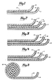
- Figure 1 is a sectional view showing one embodiment of the laminated tape used in the present invention.
- Figure 2 is a sectional view showing an alternate embodiment of the laminated tape used in the present invention.
- Figure 3 is a sectional view showing a further alternate embodiment of the laminated tape used in the present invention.
- Figure 4 is a sectional view showing a further alternate embodiment of the laminated tape used in the present invention.
- Figure 5 is a sectional view of one embodiment of the transfer tape usable with the laminated tape illustrated in Figure 1.
- Figure 6 is a pictorial view showing the laminated tape with the characters having been cut from the top layer.
- Figure 6a is a pictorial view showing the transfer tape in position to remove the cut-out characters from the laminated tape.
- Figure 7 is a pictorial view showing the cut out figures after having been transferred to the transfer tape.
- Figure 8 is a pictorial view showing the method of applying the cut out figures to the desired medium.
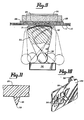
- Figure 9 is an elevational view, partially in section, showing the mechanism for applying the cutting force to the laminated tape.
- Figure 10 is a pictorial view of the cutting die in the form of a lettering chip.
- Figure 11 is a sectional view of a portion of the lettering chip as viewed along the section line 11-11 of Figure 10.
- Reference is first made to Figures 1-4 showing various embodiments of the laminated tape of the present invention. Although these embodiments illustrate various combinations of laminated structures, they all include a
first film layer 10 comprised of a relatively soft and highly flexible material capable of being cut by a cutting ridge of a cutting die. Each of these embodiments also includes asecond film layer 11 functioning to support or carry thefirst layer 10. Thissecond layer 11 is not cut during the cutting procedure. Each of the embodiments of Figures 1-4 also includes a third film layer functioning as a transfer tape to transfer the cut out figures from thefirst layer 10 to a desired medium. In the embodiment of Figure 2, this third layer is designated by thereference numeral 12, whereas in the embodiments of Figures 3 and 4, this third layer is designated by thereference numeral 13. With respect to the embodiment of Figure 1, the third layer is supplied separately from the roll oftransfer tape 22 illustrated in Figure 5. The transfer tape itself is designated by thereference numeral 14. - As will be described in greater detail below, the
first layer 10 of each of the embodiments illustrated in Figures 1-4 is capable of being cut by an elongated cutting ridge of a cutting die. In general, the physical characteristics of thisfirst layer 10 is that it is a relatively soft and flexible material. Although it is contemplated that various types of synthetic polymers such as epoxys, acrylics, vinyls and polyesters may be formulated so that they exhibit the desired physical characteristics of thefirst layer 10, thefirst layer 10 of the preferred embodiment is constructed of a low energy, cuttable polyurethane. It has been found, through testing and experimentation, that a first layer constructed of such a polyurethane provides the desired physical properties of softness and flexibility and provides a material which is capable of being cut at dramatically lower cutting forces than is needed in prior art devices. - One of the primary advantages of the softness and flexibility of the
first layer 10 is that it is cuttable with a relatively low force by a cutting ridge of a cutting die. The particular magnitude of this cutting force is one parameter which has been used by the inventor to define the desired characteristics of thefirst layer 10. A second parameter used is that of tensile strength, namely, the force needed to fracture a piece of the material by pulling two ends of the material in opposite directions. During the development of the present invention, a test was devised to determine the force needed to cut through a particular layer of material. This test was performed using a Model QC Electronic Tensile Tester manufactured by Thwing-Albert Instrument Company of Philadelphia, Pennsylvania. This device was provided with a 2, 23 kN load cell and a compression fixture to enable a compression cutting force to be exerted. A cutting die similar to thelettering chip 29 illustrated in Figure 10 was also utilized. Such cutting die included acontinuous cutting ridge 35 of finite length. As illustrated in Figure 11, the generally wedge shapedcontinuous cutting ridge 35 includes a cutting point oredge 39 and a pair of side surfaces disposed at an included angle "A" with respect to each other of approximately fifty degrees (50°). In the test apparatus, thelettering chip 29 andcutting ridge 35 was constructed of a high impact molded plastic designated as Plexiglass DR 61KO and manufactured by Rohm & Haas Company of Philadelphia, Pennsylvania. A urethane pad of Hardness 61-64 Shore C was provided to resist the cutting force. The testing . device further included means for applying and recording a given force to the cutting die. - Samples of various materials and polymer formulations were then inserted into the compression test fixture between the cutting ridge of the cutting die and the urethane pad and a cutting force was applied until the material had been cut. The force at which a 100% cut occurred was recorded and a force per linear inch of the cutting ridge was calculated. As a result of these force tests, it was determined that to obtain the advantages of the present invention and to exhibit the necessary and desired characteristics of softness and flexibility, the
first film layer 10 had to be constructed of a material which could be cut by a cutting force of no greater than about 450 N per cm length of cutting ridge. It is also contemplated that thefirst layer 10 should be at least about 25 pm thick. Materials greater than the above thickness which require a cutting force greater than 450 N per cm length, such as the cellulose acetate and materials having similar properties disclosed in the Massari Patent No. 3,558,425, do not provide the desired benefits since those materials require significantly different and more expensive types of cutting apparatus to cut thefirst layer 10. When the above test was applied to a piece ofcellulose acetate 24 pm thick, the testing apparatus which had a maximum load capability of 22.3 N, could not cut the sample. Thus, the cutting force needed for this sample of cellulose acetate was substantially greater than 880 N per cm length. Obviously, cellulose acetate or similar material with a thickness greater than 25 pm would require still greater cutting forces. Preferably, thefirst film layer 10 is constructed of a material which can be cut by a cutting force of between about 220 and 310 N per cm length of cutting ridge. - The inventor has also determined that the tensile strength of a particular material is generally linearly related to the cutting force determined in the test described above. Tensile strength of a material is conventionally determined by The American Society for Testing and Materials (ASTM) test D882. In this test, stress is applied to a material in a pulling fashion until it breaks. Tensile strength is calculated by dividing the maximum load (force) by the original cross-sectional area of the sample. The result is expressed in pounds per square inch.
- Tensile strength determinations were made on various materials and formulations which confirmed the generally linear relationship between tensile strength and cutting force. While this generally linear relationship is expected to vary somewhat for different kinds and formulations of material, it was determined that the tensile strength of the material from which the first layer is constructed should be no greater than about 70 bar and preferably no greater than about 35 bar. Tensile strength determinations conducted with respect to a sample of cellulose acetate 24 11m thick resulted in a tensile strength of about 700 bar.
- Accordingly, to achieve the benefits and advantages of the present invention, the
first layer 10 which is cuttable must be constructed of a material which is relatively soft and flexible and capable of being cut by an elongated cutting ridge of a cutting die. Further, the material of thefirst layer 10 should have a tensile strength of no greater than 70 bar. The material should also be such that a cutting force of no more than about 450 N per cm length of the cutting ridge will cut thefirst layer 10. Thefirst layer 10 should also be at least 25 11m thick. - As indicated above, the
first film layer 10 of the preferred embodiment is a urethane film formed by reacting an isocyanate monomer with one or more polyols. Specifically, the isocyanate monomer is a hexamethylene diisocyanate having an isocyanate equivalent weight of about 190. The preferred polyols include a polymeric vinyl ester acrylic copolymer (40%, by weight, solids) with a hydroxyl equivalent weight of about 400; a hydroxyl functional acrylic copolymer with a hydroxyl equivalent weight of about 800; a saturated polyester resin with a hydroxyl equivalent weight of about 1135; DB castor oil having a hydroxyl value of about 164; and a polyoxypropylene polyether having a hydroxyl equivalent weight of about 125. A catalyst such as organo tin and pigments are also added in the preferred system. Preferably, the index or ratio of isocyanate equivalence to hydroxyl equivalence is about 0.7 to 0.9 with the optimum being about 0.8. - With reference again to Figures 1-4, a
second layer 11 is disposed adjacent to and in face-to-face relationship with one surface of thefirst layer 10. The physical properties of thissecond layer 11 are not as important as the properties of thefirst layer 10 since its primary function is to provide support for and carry thefirst layer 10 during the cutting procedure. Accordingly, thesecond layer 11 can be constructed of a variety of materials such as materials having a paper base or polymer films such as polyesters or polyethylenes. Also, in general, thesecond layer 11 should be relatively hard and inflexible compared to thefirst layer 10 and should also be relatively non-elastic, to preclude the laminated film from being stretched and deformed prior or subsequent to the cutting procedure. In comparison to thefirst layer 10, thesecond layer 11 should have a tensile strength greater than 70 bar. Also, thesecond layer 11 should not be capable of being cut by a cutting ridge at cutting forces less than 450 N per cm length. - As illustrated, the lower surface of the
first layer 10 which is adjacent to the second layer 11' is provided with anadhesive coating 15. The corresponding surface of thesecond layer 11 is provided with a release liner orcoating 16 to permit portions of thefirst layer 10 to be removed or stripped from thesecond layer 11 when desired. Following removal, as will be described in greater detail below, these portions of thefirst layer 10 are positioned onto the desired medium and retained in such position by theadhesive coating 15. Accordingly, theadhesive coating 15 should be quite aggressive. In the preferred embodiment, the adhesive 15 is a generally available hot melt acrylic or water base adhesive. The specific tack or aggressiveness of the adhesive is measured by a peel test which involves placing a one-half inch wide strip of material backed with the particular adhesive in question on a substrate consisting of 1000 H Vellum drafting stock. After applying the strip with a four pound roller and waiting fifteen minutes, one end of the strip is then gripped and peeled back at 180°. The force needed to accomplish this peel is indicative of the tack or aggressiveness of the adhesive. Using this test, the preferred tack of the adhesive 15 should be about 0.4 to 0.8 N per cm for a low tack application and about 1.6 to 2.0 N per cm high tack application. The low tack is used primarily when preparing stencils, whereas the high tack is used when the adherence is intended to be permanent. - The
release coating 16 can also consist of a variety of materials. In the preferred embodiment, however, thecoating 16 is a silicone coating applied to the top surface of the second orsupport layer 11. - Each of the embodiments illustrated in Figures 1-4 also includes an associated third or transfer film layer. The primary function of this third layer is to facilitate the transfer of the cut-out figures, or the stencil as the case may be, to the desired medium. In the embodiment of Figure 2, this third or transfer layer is illustrated by the
reference numeral 12 and is disposed adjacent to the side of thefirst layer 10 opposite that of thesecond layer 11. In this particular embodiment, thethird layer 12 must be constructed of a generally flexible, hard and elastic material which enables it to be stretched without being cut during application of the cutting force. In Figure 2, thethird layer 12 is utilized to transmit the cutting force of the cutting die to thefirst layer 10 to cut thefirst layer 10 into the desired characters or figures. The material from which thethird layer 12 in Figure 2 is constructed is a material such as a polyester or polyethylene. Although thislayer 12 of Figure 2 can be constructed of a variety of materials, it must have the necessary flexibility, elasticity and toughness to prevent it from being cut by a cutting force of less than 450 N per cm length in accordance with the cutting force test previously described. - In the embodiment of Figure 2, the surface of the
third layer 12 adjacent to thefirst layer 10 is provided with a low tackadhesive layer 17 to facilitate removal of portions of thefirst layer 10 from thesecond layer 11. In such embodiment, thefirst layer 10 is provided with a release coating orsurface 18 to allow removal of the third layer.12 after the cut-out figures have been secured to the desired medium. Theadhesive coating 17 can be any common low tack adhesive such as, for example only, those having a vinyl, acrylic or urethane base. Therelease coating 18 can be any common release coating such as silicone, teflon orfluorocarbons, or can in some cases be nothing more than the top surface of thefirst layer 10. In the preferred embodiment, the adhesive 17 has a tack of less than about 0.4 N per cm as measured by the test described above. - In the embodiments of Figures 3 and 4, the third layer or transfer tape is designated by the
reference numeral 13. In these embodiments, thethird layer 13 is disposed adjacent to the surface of thesecond layer 11 opposite that of thefirst layer 10 and remains in this position during the cutting procedure. As will be described in greater detail below, after the cutting procedure, the thirdlayer transfer tape 13 is removed and placed adjacent thefirst layer 10 to transfer the cut-out figures from thefirst layer 10 to the desired medium. The third layer ortransfer tape 13 illustrated in Figures 3 and 4 can be constructed of a variety of materials since its only function, in these particular embodiments, is to facilitate the transfer of the cut-out characters from thefirst layer 10 to the desired medium. Preferably, however, thethird layer 13 in the embodiments of Figures 3 and 4 is constructed of a polyester, polypropylene, acetate, polyethylene or paper base material. - Similar to the third or
transfer layer 12 of Figure 2, thethird layer 13 of Figures 3 and 4 is provided with a low tackadhesive coating 20. Thiscoating 20 has generally the same characteristics and tack as thecoating 17 of Figure 2 and performs the same function of facilitating removal of cut-out portions of thefirst layer 10 from thesecond layer 11. In the embodiment of Figure 3 a release liner orcoating 19 is provided on the surface of thesecond layer 11 adjacent to thethird layer 13, while in the embodiment of Figure 4, the release characteristics are inherent in thesecond layer 11 itself. - In the embodiment illustrated in Figure 1, the third layer or transfer tape is provided from a
separate spool 22 as shown in Figure 5 and designated by thereference numeral 14. When using the laminated tape of Figure 1 and the third layer ortransfer tape 14 of Figure 5, thetransfer tape 14 is utilized in the same manner as thetransfer tape 13 in Figures 3 and 4 after the cutting procedure has been completed. Also, similar to the third layer ortransfer tape 13 of Figures 3 and 4, the sole purpose of thetransfer tape 14 is to assist in transferring the cut-out figures from thefirst layer 10 to the desired medium. Accordingly, it can be constructed of the same material as thethird layer 13 of Figures 3 and 4. Thetransfer tape 14 in Figure 5 is also provided with alow tack adhesive 21. This adhesive has generally the same characteristics and tack as theadhesive coating 17 of Figure 2 and theadhesive coating 20 of Figures 3 and 4 and performs the same function of facilitating removal of cut-out portions of thefirst layer 10 from thesecond layer 11. - In the cutting procedure associated with the laminated tape of the present invention, the
first layer 10 of Figures 1-4 is cut by a cutting die in the form of thelettering chip 29 illustrated in Figure 10. As shown in Figure 10, and also in Figure 11, the cutting die includes a generally wedge-shaped,continuous cutting ridge 35 having a continuous cutting point or edge 39 (Figure 11). In the preferred embodiment, thislettering chip 29 is constructed of a high impact molded plastic material such as Plexiglass DR 61 KO manufactured by Rohm & Haas Company of Philadelphia, Pennsylvania. It is contemplated, however, that different types of materials can also be used. Thelettering chip 29 includes atab 38 to facilitate handling thechip 29 and a plurality ofalignment indicia 36 to facilitate proper alignment of the character or figure 35 to be cut. - Figure 9 illustrates one embodiment of a means for applying a cutting force to the
lettering chip 29. A structure of this type is known in the art. In general, however, it includes a pair of support rails 34 (only one of which is illustrated in Figure 9) and a generally wedge shaped force generating segment rotatably mounted near its pointed end to aroller member 32 adapted for rolling movement along the support rails 34. The upper, curved surface of the wedge-shapedsegment 30 includes apad 31. This pad may be constructed of a rubber or plastic material with some resiliency. In the preferred embodiment, the pad is a urethane pad having a hardness of approximately 61-64 Shore C. The device illustrated in Figure 9 also includes a pair ofchip alignment members force resisting means 26. As shown, the cutting die orlettering chip 29 is positioned within the alignment and retainingtabs segment 30 is caused to roll against the bottom surface of thelettering chip 29 containing the cuttingridge 35 by moving theroller 32 from one end of the support rails 34 to the other. During the cutting procedure, the laminated tape comprising at least thefirst layer 10 and thesecond layer 11 is disposed between theurethane pad 31 and the bottom surface of thelettering chip 29. Then, as theroller segment 30 is rolled from one end to the other, the cutting force is applied between theurethane pad 31 and thelettering chip 29. This cutting force is sufficient to cut only thefirst layer 10, while leaving thesecond layer 11 uncut. - It should be noted that in Figure 9 the laminated tape being cut is similar to that of Figure 1. If the laminated tape of Figure 2 is cut, the cutting force applied to the cutting
ridge 35 is transmitted through the third layer 12 (Figure 2) to thefirst layer 10 which is then cut. If the embodiment of Figures 3 and 4.is cut, the cuttingridge 35 cuts only thefirst layer 10 without cutting either thesecond layer 11 or thethird layer 13. - After the cutting procedure, the laminated tape is then removed from the cutting apparatus and the cut-out figures or characters from the-
first layer 10 are transferred to the desired medium. This transfer procedure is illustrated best in Figures 6, 6a, 7 and 8. Figure 6 shows a section of the laminated tape of Figure 1 with the letters or characters having been cut-out. To transfer the cut-out letters to the desired medium, the portion of thelayer 10, except for the cut-out letters, is first removed from the base orsecond layer 11. This is accomplished by separating thelayers layer 10 off. When this is completed, the figures 24 remain on thelayer 11 as illustrated in the lower half of Figure 6a. A strip of the third layer of transfer tape 14 (Figure 5) is then cut and placed onto the top surface of the remaining cut-out figures 24 as illustrated in Figure 6a with the low tack adhesive 21 in engagement with thetop layer 10 of the cut-out figures 24. After having been placed onto the cut-out figures 24 of thefirst layer 10, thetransfer tape 14 is peeled back to remove the figures 24 from thesecond layer 11. Although the adhesive 21 on thetransfer layer 14 is a relatively low tack adhesive, it is sufficient to remove the cut-out figures 24 because of therelease layer 16 on thelayer 11. If the laminated tape of Figure 2 is used, thethird layer 12 is simply peeled back in the same manner so as to remove the cut-out figures 24 from thelayer 11. If the laminated tape of either Figures 3 or 4 is used, thetransfer tape 13 must first be removed from the lower surface of thelayer 11 and then used to remove the cut-out figures 24 in the manner described above. - Following the removal of the cut-out letters or figures 24, the resulting
transfer tape 14 includes only the cut-outletters 24 as shown in Figure 7. As illustrated, the cut-out figures 24 are aligned on thetape 14 with their adhesive side facing outwardly. To apply these cut-outcharacters 24 to the desired medium, thetransfer tape 14 is simply aligned in the desired position as illustrated in Figure 8 and placed down in that position so that the bottom surface of the cut-outletters 24 which contain theaggressive adhesive 15 secures to the desiredmedium 25. Thetransfer tape 14 which contains the relatively low tack adhesive is then removed, thereby leaving the cut-outletters 24 properly positioned on the desiredmedium 25.
Claims (5)
Priority Applications (1)
| Application Number | Priority Date | Filing Date | Title |
|---|---|---|---|
| AT83100247T ATE35110T1 (en) | 1982-01-15 | 1983-01-13 | DEVICE AND METHOD FOR PRODUCTION OF IMAGE. |
Applications Claiming Priority (2)
| Application Number | Priority Date | Filing Date | Title |
|---|---|---|---|
| US06/339,481 US4584220A (en) | 1982-01-15 | 1982-01-15 | Laminated tape |
| US339481 | 1994-11-10 |
Publications (3)
| Publication Number | Publication Date |
|---|---|
| EP0084350A2 EP0084350A2 (en) | 1983-07-27 |
| EP0084350A3 EP0084350A3 (en) | 1984-05-16 |
| EP0084350B1 true EP0084350B1 (en) | 1988-06-15 |
Family
ID=23329193
Family Applications (1)
| Application Number | Title | Priority Date | Filing Date |
|---|---|---|---|
| EP83100247A Expired EP0084350B1 (en) | 1982-01-15 | 1983-01-13 | Apparatus and method for manufacturing figures |
Country Status (6)
| Country | Link |
|---|---|
| US (1) | US4584220A (en) |
| EP (1) | EP0084350B1 (en) |
| JP (1) | JPS58164670A (en) |
| AT (1) | ATE35110T1 (en) |
| CA (1) | CA1204998A (en) |
| DE (1) | DE3377052D1 (en) |
Families Citing this family (12)
| Publication number | Priority date | Publication date | Assignee | Title |
|---|---|---|---|---|
| SE448153B (en) * | 1984-05-03 | 1987-01-26 | Frans Gunnar Waldemar Fjelkner | CLIP OR CLUTCH |
| NZ247984A (en) * | 1992-07-01 | 1994-09-27 | Lintec Corp | Plastics film for labels; produced from resin composition containing 20-80% by weight polypropylene resin and 20-80% by weight polyethylene resin |
| DE69833196T2 (en) * | 1997-06-09 | 2006-08-24 | Tesa Tape Inc. | COEXTRUDED FILMS AND THESE INCLUDING RIBBONS AND MANUFACTURED OBJECTS |
| US20070062844A1 (en) * | 2005-09-16 | 2007-03-22 | Velasquez Urey Ruben E | Cover tape and method for manufacture |
| US8247057B2 (en) * | 2005-09-16 | 2012-08-21 | 3M Innovative Properties Company | Cover tape and method for manufacture |
| EP2049609A4 (en) * | 2006-08-09 | 2014-07-09 | 3M Innovative Properties Co | Carrier tapes having tear-initiated cover tapes and methods of making thereof |
| JP2012046723A (en) * | 2010-07-30 | 2012-03-08 | Nitto Denko Corp | Application tape |
| US9524517B2 (en) * | 2011-05-06 | 2016-12-20 | Iconex Llc | Method of operating a self-service terminal to provide on-demand postage stamp labels to a postage stamp buyer and a self-service terminal therefor |
| US10016909B2 (en) | 2011-05-06 | 2018-07-10 | Iconex Llc | Roll of pre-printed stamp label stock and method of manufacturing a roll of pre-printed stamp label stock |
| US8833037B2 (en) * | 2012-04-05 | 2014-09-16 | Carlisle Intangible Company | Single ply roofing membranes with multifunctional biodegradable release liner |
| US10422138B1 (en) * | 2018-05-08 | 2019-09-24 | Carlisle Intangible, LLC | Roof membranes with removable protective sheets |
| CN114683352B (en) * | 2020-12-27 | 2023-12-01 | 上海昊佰智造精密电子股份有限公司 | Combined cutting die and use method thereof |
Family Cites Families (8)
| Publication number | Priority date | Publication date | Assignee | Title |
|---|---|---|---|---|
| GB842983A (en) * | 1955-08-30 | 1960-08-04 | Milton Alfred Bergstedt | Adhesive sheets or tapes and a method of producing them |
| US3166186A (en) * | 1962-06-25 | 1965-01-19 | Andrew B Karn | Pressure sensitive labels, label stocks, and methods for manufacturing the same |
| DE1263474B (en) * | 1962-07-25 | 1968-03-14 | Jackstaedt & Co Wilhelm | Method for producing a storage device provided with self-adhesive labels |
| US3930092A (en) * | 1969-09-24 | 1975-12-30 | Adhesive Materials Ltd | Printing characters for use in transfer printing processes |
| GB1438947A (en) * | 1972-08-08 | 1976-06-09 | Letraset International Ltd | Lettering products |
| FR2332581A1 (en) * | 1975-11-19 | 1977-06-17 | Kalbacher Bernard | Alphanumeric characters transfer system - has composition grid on which characters are arranged before transfer |
| JPS576767A (en) * | 1980-06-16 | 1982-01-13 | Teijin Ltd | Easily adhesive polyester film |
| US4374883A (en) * | 1981-10-15 | 1983-02-22 | Minnesota Mining And Manufacturing Company | Pressure-sensitive adhesive tape |
-
1982
- 1982-01-15 US US06/339,481 patent/US4584220A/en not_active Expired - Fee Related
-
1983
- 1983-01-13 EP EP83100247A patent/EP0084350B1/en not_active Expired
- 1983-01-13 DE DE8383100247T patent/DE3377052D1/en not_active Expired
- 1983-01-13 AT AT83100247T patent/ATE35110T1/en not_active IP Right Cessation
- 1983-01-14 CA CA000419525A patent/CA1204998A/en not_active Expired
- 1983-01-17 JP JP58005787A patent/JPS58164670A/en active Pending
Also Published As
| Publication number | Publication date |
|---|---|
| EP0084350A2 (en) | 1983-07-27 |
| JPS58164670A (en) | 1983-09-29 |
| US4584220A (en) | 1986-04-22 |
| CA1204998A (en) | 1986-05-27 |
| ATE35110T1 (en) | 1988-07-15 |
| EP0084350A3 (en) | 1984-05-16 |
| DE3377052D1 (en) | 1988-07-21 |
Similar Documents
| Publication | Publication Date | Title |
|---|---|---|
| US4604153A (en) | Method of manufacturing figures from a laminated tape and applying the same to a desired medium | |
| EP0084350B1 (en) | Apparatus and method for manufacturing figures | |
| US4253899A (en) | Method of making matrix free thin labels | |
| US3592722A (en) | Slidable adhesive laminate | |
| EP1685206B1 (en) | Structured paper release liner, adhesive-backed article assembly and method of making same | |
| US6440880B2 (en) | Pressure-sensitive adhesives having microstructured surfaces | |
| EP0315072B1 (en) | Pressure-sensitive adhesive layer | |
| KR100560341B1 (en) | Adhesives having a microreplicated topography and methods of making and using same | |
| US4223067A (en) | Foam-like pressure-sensitive adhesive tape | |
| EP2193769B1 (en) | Patch material | |
| JP3029047B2 (en) | Loop fastener material storage / dispensing assembly | |
| DE4431914C2 (en) | Strip of an adhesive film for a residue-free, removable adhesive and its use | |
| CA1124428A (en) | Foam-like pressure-sensitive adhesive tape | |
| EP0385647A2 (en) | Stack of pressure sensitive adhesive coated sheets | |
| EP0816462A1 (en) | Pressure-sensitive adhesive composition and pressure-sensitive adhesive sheets made therefrom, and sealants, reinforcing sheets and pressure-sensitive adhesive sheets for printing produced therefrom | |
| DE60004234T2 (en) | NOTEPAD | |
| EP1233046A1 (en) | Release liner having double-sited self-adhesive sections and use thereof in a hand-held labeler | |
| DE3801661C2 (en) | ||
| US6699565B2 (en) | Pressure-sensitive transfer adhesive tape | |
| DE69635799T2 (en) | PRESSURE-RESISTANT ADHESIVE COMPOSITION AND PRINT-SENSITIVE ADHESIVES AND SEAL MASSES, IMPRESSION FOILS, AND PRESSURE-SENSITIVE ADHESIVE PRINTED FOILS MANUFACTURED THEREFROM | |
| JPH0748551A (en) | Pressure-sensitive adhesive tape or sheet | |
| JPH0627414Y2 (en) | Decorative sheet | |
| JPH07150041A (en) | Water-base polyelectrolyte solution containing silicone for coating, its production, and its use | |
| GB1473076A (en) | ||
| EP0563510A1 (en) | Label for a polystyrene container |
Legal Events
| Date | Code | Title | Description |
|---|---|---|---|
| PUAI | Public reference made under article 153(3) epc to a published international application that has entered the european phase |
Free format text: ORIGINAL CODE: 0009012 |
|
| AK | Designated contracting states |
Designated state(s): AT BE CH DE FR GB IT LI LU NL SE |
|
| PUAL | Search report despatched |
Free format text: ORIGINAL CODE: 0009013 |
|
| AK | Designated contracting states |
Designated state(s): AT BE CH DE FR GB IT LI LU NL SE |
|
| 17P | Request for examination filed |
Effective date: 19841026 |
|
| RAP1 | Party data changed (applicant data changed or rights of an application transferred) |
Owner name: KROY INC. |
|
| GRAA | (expected) grant |
Free format text: ORIGINAL CODE: 0009210 |
|
| AK | Designated contracting states |
Kind code of ref document: B1 Designated state(s): AT BE CH DE FR GB IT LI LU NL SE |
|
| REF | Corresponds to: |
Ref document number: 35110 Country of ref document: AT Date of ref document: 19880715 Kind code of ref document: T |
|
| REF | Corresponds to: |
Ref document number: 3377052 Country of ref document: DE Date of ref document: 19880721 |
|
| ITF | It: translation for a ep patent filed |
Owner name: TOP - PATENTS - ITALO INCOLLINGO |
|
| ET | Fr: translation filed | ||
| PG25 | Lapsed in a contracting state [announced via postgrant information from national office to epo] |
Ref country code: GB Effective date: 19890113 Ref country code: AT Effective date: 19890113 |
|
| PG25 | Lapsed in a contracting state [announced via postgrant information from national office to epo] |
Ref country code: SE Effective date: 19890114 |
|
| PG25 | Lapsed in a contracting state [announced via postgrant information from national office to epo] |
Ref country code: LU Free format text: LAPSE BECAUSE OF NON-PAYMENT OF DUE FEES Effective date: 19890131 Ref country code: LI Effective date: 19890131 Ref country code: CH Effective date: 19890131 Ref country code: BE Effective date: 19890131 |
|
| PLBE | No opposition filed within time limit |
Free format text: ORIGINAL CODE: 0009261 |
|
| STAA | Information on the status of an ep patent application or granted ep patent |
Free format text: STATUS: NO OPPOSITION FILED WITHIN TIME LIMIT |
|
| 26N | No opposition filed | ||
| BERE | Be: lapsed |
Owner name: KROY INC. Effective date: 19890131 |
|
| PG25 | Lapsed in a contracting state [announced via postgrant information from national office to epo] |
Ref country code: NL Effective date: 19890801 |
|
| NLV4 | Nl: lapsed or anulled due to non-payment of the annual fee | ||
| GBPC | Gb: european patent ceased through non-payment of renewal fee | ||
| PG25 | Lapsed in a contracting state [announced via postgrant information from national office to epo] |
Ref country code: FR Free format text: LAPSE BECAUSE OF NON-PAYMENT OF DUE FEES Effective date: 19890929 |
|
| REG | Reference to a national code |
Ref country code: CH Ref legal event code: PL |
|
| PG25 | Lapsed in a contracting state [announced via postgrant information from national office to epo] |
Ref country code: DE Effective date: 19891003 |
|
| REG | Reference to a national code |
Ref country code: FR Ref legal event code: ST |
|
| EUG | Se: european patent has lapsed |
Ref document number: 83100247.2 Effective date: 19891204 |