EP0085417B1 - Biomedical stimulation lead - Google Patents
Biomedical stimulation lead Download PDFInfo
- Publication number
- EP0085417B1 EP0085417B1 EP83100823A EP83100823A EP0085417B1 EP 0085417 B1 EP0085417 B1 EP 0085417B1 EP 83100823 A EP83100823 A EP 83100823A EP 83100823 A EP83100823 A EP 83100823A EP 0085417 B1 EP0085417 B1 EP 0085417B1
- Authority
- EP
- European Patent Office
- Prior art keywords
- lead
- lead body
- tines
- helix
- electrode
- Prior art date
- Legal status (The legal status is an assumption and is not a legal conclusion. Google has not performed a legal analysis and makes no representation as to the accuracy of the status listed.)
- Expired
Links
Images
Classifications
-
- A—HUMAN NECESSITIES
- A61—MEDICAL OR VETERINARY SCIENCE; HYGIENE
- A61N—ELECTROTHERAPY; MAGNETOTHERAPY; RADIATION THERAPY; ULTRASOUND THERAPY
- A61N1/00—Electrotherapy; Circuits therefor
- A61N1/02—Details
- A61N1/04—Electrodes
- A61N1/05—Electrodes for implantation or insertion into the body, e.g. heart electrode
- A61N1/056—Transvascular endocardial electrode systems
- A61N1/057—Anchoring means; Means for fixing the head inside the heart
-
- A—HUMAN NECESSITIES
- A61—MEDICAL OR VETERINARY SCIENCE; HYGIENE
- A61N—ELECTROTHERAPY; MAGNETOTHERAPY; RADIATION THERAPY; ULTRASOUND THERAPY
- A61N1/00—Electrotherapy; Circuits therefor
- A61N1/02—Details
- A61N1/04—Electrodes
- A61N1/05—Electrodes for implantation or insertion into the body, e.g. heart electrode
- A61N1/0551—Spinal or peripheral nerve electrodes
- A61N1/0558—Anchoring or fixation means therefor
Definitions
- This invention in general relates to the field of leads for the electrical stimulation of living tissue, and more particularly, concerns a lead having improved means for anchoring the lead which result in a lead which is unusually resistant to dislodgment when placed within the epidural space.
- Electrical stimulation of the body is an increasingly important medical procedure.
- electrical stimulation of the spinal cord has proven to be effective in relieving chronic pain.
- a lead is introduced into the epidural space which surrounds the spinal cord. With the patient under local anesthesia at the point of insertion, the lead is maneuvered by the surgeon until the position is obtained in which the lead provides the maximum relief to the particular patient.
- a problem encountered in many stimulating contacts and, in particular, in the context of stimulation of the spinal cord within the epidural space, is the dislodgment of the electrode after insertion.
- US-A-4044 774 extensively discusses the techniques of spinal cord stimulation in the epidural space and the related problem of lead placement. This patent relates particularly to the structure within the lead body itself, and it does not appear to disclose anchoring apparatus external of the lead body.
- US-A-3 902 501, US-A-3 939 843, US-A-4 236 529 and US-A-4 280 551 all relate to leads employing tines for anchoring an electrical stimulation lead.
- US-A-4 236 529 also discloses flattened tines; however, the tines are flattened in a direction parallel to the axis of the lead body, and the patent discloses that the purpose of the flattening is to make the tines thinner so that they are more flexible about the lead body axis.
- the above patents all disclose that the tines engage trabeculae within the body organ such as the heart, to provide lead anchoring. Since the epidural space does not contain trabeculae or other similar tissue, extension of the tined lead to the epidural space is not evident from these patents.
- US-A-4154 247 discloses a cardiac pacer lead in which an electrode is positioned on a circular configuration of the lead so as to be displaced from the longitudinal axis of the lead and to be urged to the wall of a heart atrium by the portion of the circular configuration diametrically opposite to the electrode engaging the wall of the atrium opposite the electrode contact zone.
- US-A-4 374 527 discloses a body stimulation lead for use in the epidural space which employs a plurality of lobes defining an S-shaped configuration preformed in the lead body to assist in maintaining the position of the electrode.
- US-A-4. 285 347 discloses another electrode employing lobes for anchoring an electrode in the epidural space.
- US-A-3 866 615 and US-A-4 154 247 disclose electrodes having lobes which are employed for anchoring electrodes in the heart.
- the invention provides a biomedical stimulation lead for insertion in an epidural space comprising:
- the invention also provides a biomedical stimulation lead for insertion in an elongated narrow body cavity comprising:
- a lead 10 according to the invention is shown in FIG. 2.
- Lead 10 includes a lead body 11 and an exposed electrode 12.
- the lead body is formed in a helix shown at 15, and tines 19 are provided which resist motion of the lead through the epidural space, thus preventing lead dislodgment.
- a lead body extension member 31 spaces tines 19 from electrode 12.
- the internal structure of the lead 10 is conventional. In order to fully understand the invention, this internal structure will be briefly described with respect to the prior art epidural lead shown in FIG. 1.
- the prior art lead 20 includes a lead body 21 and an electrode 22.
- the lead body 21 includes conductor 23 and casing 24 which encloses conductor 23 and forms the external portions of the lead (except in the area of exposed electrode 22).
- conductor 23 is in the form of a helical coil having an opening or lumen 25 passing down the central axis of the coil.
- a stylet 27 having stylet handle 28 may be inserted into the lumen so that it extends axially along the length of the lead body 21 in order to stiffen the lead while it is being inserted. After the lead is inserted, the stylet 27 is removed.
- end 29 is adapted to be connected to a source of an electronic pulse, such as a pulse generator, a receiver or a lead extension (not shown) and the electrode 22 is located at or near the other end of the lead.
- a source of an electronic pulse such as a pulse generator, a receiver or a lead extension (not shown) and the electrode 22 is located at or near the other end of the lead.
- the end 29 of the lead which is connected to the pulse source is - termed the proximal end of the lead and in opposite end identifiable by the electrode 22 is termed the distal end of the lead.
- a portion of the lead body is formed into a helix.
- the helix has two full turns with the length of the two turns preferably approximately 25.4 mm (1 in) and the diameter of the helix being preferably about 5.1 mm (.2 in).
- the invention contemplates any combination of helix diameter, number of turns, and spacing which provides a helix that will fit within the epidural space without creating undesirable pressures on the dura and other structures in the i region.
- the helix is a left-hand helix looking from the forward end of the lead toward the rear.
- the casing of the lead body 10 is preferably formed of polyurethane and the helix is formed by molding the polyurethane in a heated press. Other material such as silicone rubber and other methods of forming a helix may be used.
- Lead 10 also includes the tined piece part 30.
- This piece part 30, which perhaps best can be seen in FIG. 3, consists of a hollow cylindrical extension 31, and the tines 19.
- the entire piece part is molded of polyurethane in a heat press.
- Piece part 30 is connected to lead body 10 by electrode 12.
- Electrode 12 is swaged onto the lead body 10 and piece part 30 so that the ends 13A and 13B pierce through casing 34 and hollow cylindrical extension 31 of the piece part 30 respectively to hold them together.
- the method of manufacturing using the electrode to securely fasten the piece part 30 to lead body 10 and, at the same time, make electrical contact to conductor 23 is more fully described in EP-A-0 085 416 and will not be discussed further here.
- Extension 31 extends substantially parallel to the axis of said lead body 34.
- Tines 19 are preferably formed in the form of small rectangular plank-like members about 2.0 mm (.08 in) long, 0.25 mm (.01 inch) thick and 0.30 mm (.012 in) in width, with the 0.30 mm (.012 in) width preferably being aligned in a plane substantially perpendicular to the axis of the lead body 10 and extension 31, so that they are substantially flat in this plane.
- the tines extend substantially perpendicular from the surface of extension 31.
- Extension member 31 as shown is preferably of a length which places the tines 19 about 7.6 mm (.3 in) from the end 13B of electrode 12.
- Hollow cylindrical extension 31 is preferably about 1.0 mm (.04 in) in diameter which is the same as the diameter of lead body 10.
- the invention contemplates that any size and shape of tines and any dimensions of extension 31 may be used that are consistent with: the tines and extensions being able to be inserted through a Touhy needle; with the tines serving to impede motion in the axial direction; and with the tines not being so long as to create undesirable pressure on the dura and other structures within the epidural space.
- the spacing of helix 15, electrode 12 and tines 19 are such that electrode 12 falls approximately 1/4 to 1/2 of the distance from tines 19 to helix 15.
- the tines 19 and helix 15 are close enough to the electrode to provide a significant stabilization effect, and not so close that fibrosis or other tissue buildup about the tines and helix will interfere with the electrical stimulation at the electrode.
- the helix, extension and tines as thus described cooperate to provide an electrode which is significantly more stable in the period immediately after implant than other leads previously designed for the epidural space.
- the body creates fibrosis and other tissue buildup around tines 19 which serves to firmly hold them in place.
- an electrode is provided which is secured between two fixation points.
- Helix 15 serves a dual purpose in the invention. It not only serves as a fixation point as described above, but also serves as a means for absorbing shocks supplied to the lead body.
- the helical turns expand and contract in the case of sudden forces applied to lead body 10 which tends to isolate electrode 12 from these forces.
- the drag provided by flattened tines 19 in the epidural space also tends to cooperate with the extendabil- ity of the helix 15 to help isolate electrode 12 from sudden movements or shocks to lead body 10. It is noted that the helix effectively provides significantly more surface opposing motion in a direction along the axis of the lead than other prior art lead anchoring structures.
- the helix and tines also stabilize the lead in the directions perpendicular to the axis.
- the entire lead can be inserted into the epidural space through conventional methods.
- a stylet such as shown at 27 and 28 in FIG. 1 is inserted into lead body 10 which straightens the turns of helix 15.
- the entire lead may then be inserted into the body in the conventional manner through a Touhy needle, with the tines flattening down against extension 31 upon insertion into the needle.
- the flattening of the tines serves to make entry into the needle easier.
- the tines 19 re-extend themselves after padding through the needle.
- helix 15 reforms to cooperate with the tines in stabilizing the lead.
- tines would be effective in the epidural space, since in all previous applications of tines trabeculae or other natural body tissues were always available to interact with the tines. Further, it was believed that the tines may be too traumatic for use in the epidural space. Surprisingly, the tines have proven to be an effective anchor without causing trauma. It has been found that the helix provides surprisingly increased anchoring force than other prior art lead anchoring structures. In addition, the helix has the advantage that almost any number of turns can be formed without greatly affecting the ability of the surgeon to collapse the turns by insertion of the stylet and to pass the lead through the Touhy needle.
Description
- This invention in general relates to the field of leads for the electrical stimulation of living tissue, and more particularly, concerns a lead having improved means for anchoring the lead which result in a lead which is unusually resistant to dislodgment when placed within the epidural space.
- Electrical stimulation of the body is an increasingly important medical procedure. In particular, electrical stimulation of the spinal cord has proven to be effective in relieving chronic pain. In this stimulation context, a lead is introduced into the epidural space which surrounds the spinal cord. With the patient under local anesthesia at the point of insertion, the lead is maneuvered by the surgeon until the position is obtained in which the lead provides the maximum relief to the particular patient. A problem encountered in many stimulating contacts and, in particular, in the context of stimulation of the spinal cord within the epidural space, is the dislodgment of the electrode after insertion. This problem arises from a number of factors, including: the lack of structure within the epidural space which might engage the lead and prevent it from moving; the fact that the dura and surrounding tissue of the spinal cord are extremely sensitive and considerable pain and possible permanent damage can result if this region is traumatized, making gross anchoring techniques such as penetration of fixation to the tissue impossible; and the fact that 10 cm to 20 cm of lead may extend into the epidural space from the point of entry (at which point the lead can be firmly anchored just outside the epidural space). Dislodgment of the stimulation electrode tip after insertion may substantially lessen the relief the treatment provides, or make the treatment completely ineffective.
- US-A-4044 774 extensively discusses the techniques of spinal cord stimulation in the epidural space and the related problem of lead placement. This patent relates particularly to the structure within the lead body itself, and it does not appear to disclose anchoring apparatus external of the lead body.
- US-A-3 902 501, US-A-3 939 843, US-A-4 236 529 and US-A-4 280 551 all relate to leads employing tines for anchoring an electrical stimulation lead. US-A-4 236 529 also discloses flattened tines; however, the tines are flattened in a direction parallel to the axis of the lead body, and the patent discloses that the purpose of the flattening is to make the tines thinner so that they are more flexible about the lead body axis. The above patents all disclose that the tines engage trabeculae within the body organ such as the heart, to provide lead anchoring. Since the epidural space does not contain trabeculae or other similar tissue, extension of the tined lead to the epidural space is not evident from these patents.
- US-A-4154 247 discloses a cardiac pacer lead in which an electrode is positioned on a circular configuration of the lead so as to be displaced from the longitudinal axis of the lead and to be urged to the wall of a heart atrium by the portion of the circular configuration diametrically opposite to the electrode engaging the wall of the atrium opposite the electrode contact zone.
- US-A-4 374 527 discloses a body stimulation lead for use in the epidural space which employs a plurality of lobes defining an S-shaped configuration preformed in the lead body to assist in maintaining the position of the electrode. US-A-4. 285 347 discloses another electrode employing lobes for anchoring an electrode in the epidural space. US-A-3 866 615 and US-A-4 154 247 disclose electrodes having lobes which are employed for anchoring electrodes in the heart.
- It is an object of the invention to provide a biomedical stimulation lead for insertion in an epidural space having improved anchoring characteristics without traumatizing the surrounding body tissue. It is also an object of the invention to provide a stimulation lead which is particularly well suited for stable placement within the epidural space.
- It is a further object of the invention to provide a stimulation lead which particularly resists movement in a direction parallel to the axis of the lead and which absorbs various shocks which might otherwise tend to move the lead.
- It is a further object of the invention to provide a lead which satisfies the above objects and at . the same time can be inserted into the epidural space using conventional techniques.
- The invention provides a biomedical stimulation lead for insertion in an epidural space comprising:
- - a lead body having a distal end and a proximal end, including a conductor and an external casing made of pliable material generally inert to body fluids, the casing enclosing the conductor; and
- - an exposed electrode mounted on the lead body for stimulating within the epidural space, the electrode being conductively connected to the conductor, characterized in that
- - first anchoring means are mounted adjacent the distal end of the lead body for anchoring by fibrosis within the epidural space;
- - the electrode is spaced proximally away from the first anchoring means; and
- - the lead body is formed in a helix at a location proximally spaced from the electrode, the helix defining second anchoring means to hold the lead body within its position in the epidural space and for absorbing intermittent longitudinal pressure on the lead body in a proximal direction.
- The invention also provides a biomedical stimulation lead for insertion in an elongated narrow body cavity comprising:
- - a lead body having a distal end and a proximal end, including a conductor and an external casing made of pliable material generally insert to body fluids, the casing enclosing the conductor; and
- - a stimulation electrode mounted on the lead body and conductively connected to the conductor, characterized in that
- - a plurality of pliable tines are mounted on the lead body adjacent the distal end of the lead body, generally perpendicular to a longitudinal axis of lead body, for attachment by fibrosis within the body cavity;
- - a helix is formed in the lead body at a first location spaced away from the tines, the helix being sized to define anchoring means and for absorbing intermittent longitudinal pressure on the lead body in a proximal direction; and
- - the stimulation electrode is mounted at a second location between the tines and the helix.
- It has been found that the invention as thus described provides a lead with greatly improved stability and freedom from dislodgment within the epidural space. The foregoing and additional features, objects and advantages of the invention will become apparent from the following detailed description when read in conjunction with the accompanying drawings.
- In the drawing:
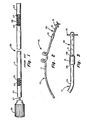
- FIG. 1 is a partial cutaway view of a prior art lead, showing the internal structure of the lead body and the placement and use of a stylet;
- FIG. 2 is a perspective view of a preferred embodiment of a lead according to the present invention; and
- FIG. 3 is a side view of the forward portion of the lead shown in FIG. 2.
- A
lead 10 according to the invention is shown in FIG. 2.Lead 10 includes a lead body 11 and an exposedelectrode 12.. The lead body is formed in a helix shown at 15, andtines 19 are provided which resist motion of the lead through the epidural space, thus preventing lead dislodgment. A leadbody extension member 31 spaces tines 19 fromelectrode 12. - The internal structure of the
lead 10 is conventional. In order to fully understand the invention, this internal structure will be briefly described with respect to the prior art epidural lead shown in FIG. 1. Theprior art lead 20 includes alead body 21 and anelectrode 22. Thelead body 21 includesconductor 23 andcasing 24 which enclosesconductor 23 and forms the external portions of the lead (except in the area of exposed electrode 22). Generally,conductor 23 is in the form of a helical coil having an opening orlumen 25 passing down the central axis of the coil. Astylet 27 havingstylet handle 28 may be inserted into the lumen so that it extends axially along the length of thelead body 21 in order to stiffen the lead while it is being inserted. After the lead is inserted, thestylet 27 is removed. In the typical lead,end 29 is adapted to be connected to a source of an electronic pulse, such as a pulse generator, a receiver or a lead extension (not shown) and theelectrode 22 is located at or near the other end of the lead. Hereinafter theend 29 of the lead which is connected to the pulse source is - termed the proximal end of the lead and in opposite end identifiable by theelectrode 22 is termed the distal end of the lead. - The principle features of the invention now are more fully described in reference to FIG. 2. Shown at 15, in the preferred embodiment of the invention, a portion of the lead body is formed into a helix. As shown, the helix has two full turns with the length of the two turns preferably approximately 25.4 mm (1 in) and the diameter of the helix being preferably about 5.1 mm (.2 in). However, the invention contemplates any combination of helix diameter, number of turns, and spacing which provides a helix that will fit within the epidural space without creating undesirable pressures on the dura and other structures in the i region. Preferably the helix is a left-hand helix looking from the forward end of the lead toward the rear. The casing of the
lead body 10 is preferably formed of polyurethane and the helix is formed by molding the polyurethane in a heated press. Other material such as silicone rubber and other methods of forming a helix may be used. -
Lead 10 also includes thetined piece part 30. Thispiece part 30, which perhaps best can be seen in FIG. 3, consists of a hollowcylindrical extension 31, and thetines 19. The entire piece part is molded of polyurethane in a heat press.Piece part 30 is connected tolead body 10 byelectrode 12.Electrode 12 is swaged onto thelead body 10 and piecepart 30 so that theends casing 34 and hollowcylindrical extension 31 of thepiece part 30 respectively to hold them together. The method of manufacturing using the electrode to securely fasten thepiece part 30 to leadbody 10 and, at the same time, make electrical contact toconductor 23 is more fully described in EP-A-0 085 416 and will not be discussed further here. - The principle features of the
piece part 30 of concern for purposes of the present invention areextension 31 andtines 19.Extension 31 extends substantially parallel to the axis of saidlead body 34.Tines 19 are preferably formed in the form of small rectangular plank-like members about 2.0 mm (.08 in) long, 0.25 mm (.01 inch) thick and 0.30 mm (.012 in) in width, with the 0.30 mm (.012 in) width preferably being aligned in a plane substantially perpendicular to the axis of thelead body 10 andextension 31, so that they are substantially flat in this plane. Preferably the tines extend substantially perpendicular from the surface ofextension 31. Substantially here means that the extension is sufficiently parallel and the tines are sufficiently flat and sufficiently perpendicular so that the major portion of the tine surface area opposes motion through the epidural space in a direction parallel to the axis of the lead.Extension member 31 as shown is preferably of a length which places thetines 19 about 7.6 mm (.3 in) from theend 13B ofelectrode 12. Hollowcylindrical extension 31 is preferably about 1.0 mm (.04 in) in diameter which is the same as the diameter oflead body 10. The invention contemplates that any size and shape of tines and any dimensions ofextension 31 may be used that are consistent with: the tines and extensions being able to be inserted through a Touhy needle; with the tines serving to impede motion in the axial direction; and with the tines not being so long as to create undesirable pressure on the dura and other structures within the epidural space. - In the preferred embodiment, the spacing of
helix 15,electrode 12 andtines 19 are such thatelectrode 12 falls approximately 1/4 to 1/2 of the distance fromtines 19 tohelix 15. Thetines 19 andhelix 15 are close enough to the electrode to provide a significant stabilization effect, and not so close that fibrosis or other tissue buildup about the tines and helix will interfere with the electrical stimulation at the electrode. The helix, extension and tines as thus described cooperate to provide an electrode which is significantly more stable in the period immediately after implant than other leads previously designed for the epidural space. Moreover, after implant, the body creates fibrosis and other tissue buildup aroundtines 19 which serves to firmly hold them in place. Thus, an electrode is provided which is secured between two fixation points. -
Helix 15 serves a dual purpose in the invention. It not only serves as a fixation point as described above, but also serves as a means for absorbing shocks supplied to the lead body. The helical turns expand and contract in the case of sudden forces applied to leadbody 10 which tends to isolateelectrode 12 from these forces. The drag provided by flattenedtines 19 in the epidural space also tends to cooperate with the extendabil- ity of thehelix 15 to help isolateelectrode 12 from sudden movements or shocks to leadbody 10. It is noted that the helix effectively provides significantly more surface opposing motion in a direction along the axis of the lead than other prior art lead anchoring structures. The helix and tines also stabilize the lead in the directions perpendicular to the axis. - The entire lead can be inserted into the epidural space through conventional methods. Prior to insertion a stylet such as shown at 27 and 28 in FIG. 1 is inserted into
lead body 10 which straightens the turns ofhelix 15. The entire lead may then be inserted into the body in the conventional manner through a Touhy needle, with the tines flattening down againstextension 31 upon insertion into the needle. The flattening of the tines serves to make entry into the needle easier. Thetines 19 re-extend themselves after padding through the needle. After removal of the stylet,helix 15 reforms to cooperate with the tines in stabilizing the lead. - Previous to the present invention, it was not believed that tines would be effective in the epidural space, since in all previous applications of tines trabeculae or other natural body tissues were always available to interact with the tines. Further, it was believed that the tines may be too traumatic for use in the epidural space. Surprisingly, the tines have proven to be an effective anchor without causing trauma. It has been found that the helix provides surprisingly increased anchoring force than other prior art lead anchoring structures. In addition, the helix has the advantage that almost any number of turns can be formed without greatly affecting the ability of the surgeon to collapse the turns by insertion of the stylet and to pass the lead through the Touhy needle.
- There has been described a novel biomedical stimulation lead that provides for greatly improved electrode stability, and at the same time can be inserted into the epidural space by conventional means. A wide variety of materials may be used for forming the
casing 34 of the lead body, theextension 31, and thetines 19, so long as the material is pliable and is resistant to body fluids. Clearly, now that the invention has been described, a wide variety of dimensions for the elements such as thehelix 15, theextension 31 and thetines 19 may be chosen by those skilled in the art to arrive at the desired characteristics as described.
Claims (8)
Applications Claiming Priority (2)
| Application Number | Priority Date | Filing Date | Title |
|---|---|---|---|
| US06/344,124 US4414986A (en) | 1982-01-29 | 1982-01-29 | Biomedical stimulation lead |
| US344124 | 1994-11-23 |
Publications (2)
| Publication Number | Publication Date |
|---|---|
| EP0085417A1 EP0085417A1 (en) | 1983-08-10 |
| EP0085417B1 true EP0085417B1 (en) | 1986-08-06 |
Family
ID=23349154
Family Applications (1)
| Application Number | Title | Priority Date | Filing Date |
|---|---|---|---|
| EP83100823A Expired EP0085417B1 (en) | 1982-01-29 | 1983-01-28 | Biomedical stimulation lead |
Country Status (5)
| Country | Link |
|---|---|
| US (1) | US4414986A (en) |
| EP (1) | EP0085417B1 (en) |
| JP (1) | JPS58133262A (en) |
| DE (1) | DE3365038D1 (en) |
| ES (1) | ES270071Y (en) |
Cited By (1)
| Publication number | Priority date | Publication date | Assignee | Title |
|---|---|---|---|---|
| US9320891B2 (en) | 2008-04-02 | 2016-04-26 | Boston Scientific Neuromodulation Corporation | Lead anchor for implantable devices and methods of manufacture and use |
Families Citing this family (169)
| Publication number | Priority date | Publication date | Assignee | Title |
|---|---|---|---|---|
| US4549556A (en) * | 1982-12-08 | 1985-10-29 | Cordis Corporation | Implantable lead |
| US4800898A (en) * | 1983-10-07 | 1989-01-31 | Cordis Corporation | Neural stimulator electrode element and lead |
| US4643202A (en) * | 1985-04-15 | 1987-02-17 | Cordis Corporation | Multi-material insulation sheath for pacer lead |
| US4706682A (en) * | 1985-08-21 | 1987-11-17 | Minnesota Mining And Manufacturing Company | External ear canal electrode to be placed proximate the tympanic membrane |
| US4722353A (en) * | 1985-09-16 | 1988-02-02 | Intermedics, Inc. | Stabilizer for implantable electrode |
| EP0328597A4 (en) * | 1987-07-24 | 1992-07-08 | Cochlear Pty. Ltd. | Apparatus and method for insertion of cochlear electrode assembly |
| US4898183A (en) * | 1987-07-24 | 1990-02-06 | Cochlear Pty. Limited | Apparatus and method for insertion of cochlear electrode assembly |
| US5002053A (en) * | 1989-04-21 | 1991-03-26 | University Of Arkansas | Method of and device for inducing locomotion by electrical stimulation of the spinal cord |
| US4998975A (en) * | 1989-10-30 | 1991-03-12 | Siemens-Pacesetter, Inc. | Travenously placed defibrillation leads |
| US5366493A (en) * | 1991-02-04 | 1994-11-22 | Case Western Reserve University | Double helix functional stimulation electrode |
| EP0559933A1 (en) * | 1992-03-10 | 1993-09-15 | Pacesetter AB | Electrode assembly for an implantable defibrillator/cardioverter |
| EP0559932A1 (en) * | 1992-03-10 | 1993-09-15 | Pacesetter AB | Implantable assembly for defibrillating or cardioverting a heart |
| US5257634A (en) * | 1992-07-16 | 1993-11-02 | Angeion Corporation | Low impedence defibrillation catheter electrode |
| SE9203733D0 (en) * | 1992-12-11 | 1992-12-11 | Siemens Elema Ab | defibrillation |
| US5387233A (en) * | 1993-01-11 | 1995-02-07 | Incontrol, Inc. | Intravenous cardiac lead with improved fixation and method |
| US5476498A (en) * | 1994-08-15 | 1995-12-19 | Incontrol, Inc. | Coronary sinus channel lead and method |
| US5733322A (en) * | 1995-05-23 | 1998-03-31 | Medtronic, Inc. | Positive fixation percutaneous epidural neurostimulation lead |
| US5609621A (en) * | 1995-08-04 | 1997-03-11 | Medtronic, Inc. | Right ventricular outflow tract defibrillation lead |
| US6073048A (en) * | 1995-11-17 | 2000-06-06 | Medtronic, Inc. | Baroreflex modulation with carotid sinus nerve stimulation for the treatment of heart failure |
| US5772693A (en) | 1996-02-09 | 1998-06-30 | Cardiac Control Systems, Inc. | Single preformed catheter configuration for a dual-chamber pacemaker system |
| US6038472A (en) * | 1997-04-29 | 2000-03-14 | Medtronic, Inc. | Implantable defibrillator and lead system |
| DE19838360A1 (en) * | 1998-04-22 | 1999-10-28 | Biotronik Mess & Therapieg | Vascular electrode line |
| EP0951920B1 (en) | 1998-04-22 | 2004-10-20 | BIOTRONIK Mess- und Therapiegeräte GmbH & Co Ingenieurbüro Berlin | Electrode cable for attachement to a vessel wall |
| US6161047A (en) | 1998-04-30 | 2000-12-12 | Medtronic Inc. | Apparatus and method for expanding a stimulation lead body in situ |
| US6319241B1 (en) * | 1998-04-30 | 2001-11-20 | Medtronic, Inc. | Techniques for positioning therapy delivery elements within a spinal cord or a brain |
| EP1149085A1 (en) | 1999-01-27 | 2001-10-31 | Eli Lilly And Company | Aminoalkylbenzofurans as serotonin (5-ht(2c)) agonists |
| US6161029A (en) * | 1999-03-08 | 2000-12-12 | Medtronic, Inc. | Apparatus and method for fixing electrodes in a blood vessel |
| US6321123B1 (en) | 1999-03-08 | 2001-11-20 | Medtronic Inc. | J-shaped coronary sinus lead |
| US6832115B2 (en) * | 2000-08-17 | 2004-12-14 | William N. Borkan | Catheter leads for the intrathecal space and method of use |
| US7200446B2 (en) * | 1999-07-21 | 2007-04-03 | Borkan William N | Catheter leads for the intrathecal space and method of use |
| US6826428B1 (en) * | 2000-04-11 | 2004-11-30 | The Board Of Regents Of The University Of Texas System | Gastrointestinal electrical stimulation |
| WO2001076690A1 (en) * | 2000-04-11 | 2001-10-18 | The Board Of Regents Of The University Of Texas System | Gastrointestinal electrical stimulation |
| US8761903B2 (en) * | 2000-10-11 | 2014-06-24 | The Board Of Regents Of The University Of Texas | Gastrointestinal electrical stimulation |
| US8467874B2 (en) * | 2000-04-11 | 2013-06-18 | The Board Of Regents Of The University Of Texas System | Gastrointestinal electrical stimulation |
| DE10114725A1 (en) * | 2001-03-21 | 2002-09-26 | Biotronik Mess & Therapieg | Intravascular lead |
| US6999819B2 (en) | 2001-08-31 | 2006-02-14 | Medtronic, Inc. | Implantable medical electrical stimulation lead fixation method and apparatus |
| US6745079B2 (en) * | 2001-11-07 | 2004-06-01 | Medtronic, Inc. | Electrical tissue stimulation apparatus and method |
| US8239045B2 (en) | 2003-06-04 | 2012-08-07 | Synecor Llc | Device and method for retaining a medical device within a vessel |
| JP4616252B2 (en) | 2003-06-04 | 2011-01-19 | シネコー・エルエルシー | Intravascular electrophysiology system and method |
| US7617007B2 (en) | 2003-06-04 | 2009-11-10 | Synecor Llc | Method and apparatus for retaining medical implants within body vessels |
| US7082336B2 (en) | 2003-06-04 | 2006-07-25 | Synecor, Llc | Implantable intravascular device for defibrillation and/or pacing |
| WO2005058415A2 (en) | 2003-12-12 | 2005-06-30 | Synecor, Llc | Implantable medical device having pre-implant exoskeleton |
| US20120277839A1 (en) | 2004-09-08 | 2012-11-01 | Kramer Jeffery M | Selective stimulation to modulate the sympathetic nervous system |
| US9205261B2 (en) | 2004-09-08 | 2015-12-08 | The Board Of Trustees Of The Leland Stanford Junior University | Neurostimulation methods and systems |
| JP5132310B2 (en) | 2004-09-08 | 2013-01-30 | スパイナル・モデュレーション・インコーポレイテッド | Neural stimulation method and system |
| US20070073354A1 (en) | 2005-09-26 | 2007-03-29 | Knudson Mark B | Neural blocking therapy |
| US20070100411A1 (en) * | 2005-10-27 | 2007-05-03 | Medtronic, Inc. | Implantable medical electrical stimulation lead fixation method and apparatus |
| US8195296B2 (en) | 2006-03-03 | 2012-06-05 | Ams Research Corporation | Apparatus for treating stress and urge incontinence |
| WO2007117538A2 (en) * | 2006-04-03 | 2007-10-18 | Innerpulse, Inc. | Flexible interconnect assembly for implantable medical devices |
| WO2007114875A1 (en) * | 2006-04-04 | 2007-10-11 | Ams Research Corporation | Apparatus for implanting neural stimulation leads |
| US8135476B2 (en) | 2006-04-27 | 2012-03-13 | Medtronic, Inc. | Implantable medical electrical stimulation lead fixation method and apparatus |
| US8204569B2 (en) * | 2006-04-27 | 2012-06-19 | Medtronic, Inc. | Implantable medical electrical stimulation lead fixation method and apparatus |
| US8145323B2 (en) * | 2006-04-27 | 2012-03-27 | Medtronic, Inc. | Implantable medical electrical stimulation lead fixation method and apparatus |
| US8200343B2 (en) * | 2006-04-27 | 2012-06-12 | Medtronic, Inc. | Implantable medical electrical stimulation lead fixation method and apparatus |
| US20070282410A1 (en) * | 2006-04-28 | 2007-12-06 | Cross Thomas E Jr | Implantable medical lead assemblies with improved flexibility and extensibility and having a substantially two-dimensional nature |
| US20070265675A1 (en) * | 2006-05-09 | 2007-11-15 | Ams Research Corporation | Testing Efficacy of Therapeutic Mechanical or Electrical Nerve or Muscle Stimulation |
| US9020597B2 (en) | 2008-11-12 | 2015-04-28 | Endostim, Inc. | Device and implantation system for electrical stimulation of biological systems |
| WO2007145913A1 (en) * | 2006-06-05 | 2007-12-21 | Ams Research Corporation | Electrical muscle stimulation to treat fecal incontinence and/or pelvic prolapse |
| US20090012592A1 (en) * | 2006-07-10 | 2009-01-08 | Ams Research Corporation | Tissue anchor |
| US8160710B2 (en) * | 2006-07-10 | 2012-04-17 | Ams Research Corporation | Systems and methods for implanting tissue stimulation electrodes in the pelvic region |
| US9724510B2 (en) | 2006-10-09 | 2017-08-08 | Endostim, Inc. | System and methods for electrical stimulation of biological systems |
| US9345879B2 (en) | 2006-10-09 | 2016-05-24 | Endostim, Inc. | Device and implantation system for electrical stimulation of biological systems |
| US20150224310A1 (en) | 2006-10-09 | 2015-08-13 | Endostim, Inc. | Device and Implantation System for Electrical Stimulation of Biological Systems |
| US11577077B2 (en) | 2006-10-09 | 2023-02-14 | Endostim, Inc. | Systems and methods for electrical stimulation of biological systems |
| US9186511B2 (en) | 2006-10-13 | 2015-11-17 | Cyberonics, Inc. | Obstructive sleep apnea treatment devices, systems and methods |
| ES2722849T3 (en) | 2006-10-13 | 2019-08-19 | Cyberonics Inc | Devices and systems for the treatment of obstructive sleep apnea |
| US9205262B2 (en) | 2011-05-12 | 2015-12-08 | Cyberonics, Inc. | Devices and methods for sleep apnea treatment |
| US8855771B2 (en) | 2011-01-28 | 2014-10-07 | Cyberonics, Inc. | Screening devices and methods for obstructive sleep apnea therapy |
| US9913982B2 (en) | 2011-01-28 | 2018-03-13 | Cyberonics, Inc. | Obstructive sleep apnea treatment devices, systems and methods |
| US9744354B2 (en) | 2008-12-31 | 2017-08-29 | Cyberonics, Inc. | Obstructive sleep apnea treatment devices, systems and methods |
| WO2008070808A2 (en) | 2006-12-06 | 2008-06-12 | Spinal Modulation, Inc. | Expandable stimulation leads and methods of use |
| WO2008070807A2 (en) | 2006-12-06 | 2008-06-12 | Spinal Modulation, Inc. | Delivery devices, systems and methods for stimulating nerve tissue on multiple spinal levels |
| US9314618B2 (en) | 2006-12-06 | 2016-04-19 | Spinal Modulation, Inc. | Implantable flexible circuit leads and methods of use |
| JP5562648B2 (en) * | 2007-01-29 | 2014-07-30 | スパイナル・モデュレーション・インコーポレイテッド | Non-stitched top retaining mechanism |
| US8244378B2 (en) | 2007-01-30 | 2012-08-14 | Cardiac Pacemakers, Inc. | Spiral configurations for intravascular lead stability |
| US20080183255A1 (en) * | 2007-01-30 | 2008-07-31 | Cardiac Pacemakers, Inc. | Side port lead delivery system |
| US7917230B2 (en) | 2007-01-30 | 2011-03-29 | Cardiac Pacemakers, Inc. | Neurostimulating lead having a stent-like anchor |
| US20080183264A1 (en) * | 2007-01-30 | 2008-07-31 | Cardiac Pacemakers, Inc. | Electrode configurations for transvascular nerve stimulation |
| US20080183187A1 (en) * | 2007-01-30 | 2008-07-31 | Cardiac Pacemakers, Inc. | Direct delivery system for transvascular lead |
| US7949409B2 (en) * | 2007-01-30 | 2011-05-24 | Cardiac Pacemakers, Inc. | Dual spiral lead configurations |
| US20080183265A1 (en) * | 2007-01-30 | 2008-07-31 | Cardiac Pacemakers, Inc. | Transvascular lead with proximal force relief |
| US9427573B2 (en) | 2007-07-10 | 2016-08-30 | Astora Women's Health, Llc | Deployable electrode lead anchor |
| US20100049289A1 (en) | 2007-07-10 | 2010-02-25 | Ams Research Corporation | Tissue anchor |
| US20090204173A1 (en) | 2007-11-05 | 2009-08-13 | Zi-Ping Fang | Multi-Frequency Neural Treatments and Associated Systems and Methods |
| US8019443B2 (en) | 2008-04-01 | 2011-09-13 | Boston Scientific Neuromodulation Corporation | Anchoring units for leads of implantable electric stimulation systems and methods of making and using |
| CN102112177A (en) * | 2008-05-02 | 2011-06-29 | 梅德特龙尼克有限公司 | Self expanding electrode cuff |
| EP2303397B1 (en) * | 2008-06-20 | 2014-04-23 | Cochlear Limited | Strain relief in an implantable electrode assembly |
| EP3714771A1 (en) * | 2008-10-01 | 2020-09-30 | Inspire Medical Systems, Inc. | System for treating sleep apnea transvenously |
| EP2373378B1 (en) | 2008-10-27 | 2017-04-26 | Spinal Modulation Inc. | Selective stimulation systems and signal parameters for medical conditions |
| US9327121B2 (en) | 2011-09-08 | 2016-05-03 | Nevro Corporation | Selective high frequency spinal cord modulation for inhibiting pain, including cephalic and/or total body pain with reduced side effects, and associated systems and methods |
| US8255057B2 (en) | 2009-01-29 | 2012-08-28 | Nevro Corporation | Systems and methods for producing asynchronous neural responses to treat pain and/or other patient conditions |
| US20100179626A1 (en) * | 2009-01-09 | 2010-07-15 | Medtronic, Inc. | System and method for implanting a paddle lead |
| US20100179561A1 (en) * | 2009-01-09 | 2010-07-15 | Medtronic, Inc. | Tool for retracting a tine element of a medical lead |
| US9539433B1 (en) | 2009-03-18 | 2017-01-10 | Astora Women's Health, Llc | Electrode implantation in a pelvic floor muscular structure |
| EP2411091A4 (en) | 2009-03-24 | 2012-09-12 | Spinal Modulation Inc | Pain management with stimulation subthreshold to paresthesia |
| JP2012521864A (en) | 2009-03-31 | 2012-09-20 | インスパイア・メディカル・システムズ・インコーポレイテッド | Percutaneous access method in a system for treating sleep-related abnormal breathing |
| ES2624748T3 (en) | 2009-04-22 | 2017-07-17 | Nevro Corporation | Selective high frequency modulation of the spinal cord for pain inhibition with reduced side effects, and associated systems and methods |
| EP2756864B1 (en) | 2009-04-22 | 2023-03-15 | Nevro Corporation | Spinal cord modulation systems for inducing paresthetic and anesthetic effects |
| US9887470B2 (en) | 2009-04-27 | 2018-02-06 | Boston Scienific Neuromodulation Corporation | Torque lock anchor and methods and devices using the anchor |
| US9352147B2 (en) | 2009-04-27 | 2016-05-31 | Boston Scientific Neuromodulation Corporation | Torque lock anchor and methods and devices using the anchor |
| US9259569B2 (en) | 2009-05-15 | 2016-02-16 | Daniel M. Brounstein | Methods, systems and devices for neuromodulating spinal anatomy |
| US8412349B2 (en) * | 2009-06-04 | 2013-04-02 | Boston Scientific Neuromodulation Corporation | Three-piece button anchor and methods and devices using the anchor |
| US8498710B2 (en) | 2009-07-28 | 2013-07-30 | Nevro Corporation | Linked area parameter adjustment for spinal cord stimulation and associated systems and methods |
| US8380312B2 (en) * | 2009-12-31 | 2013-02-19 | Ams Research Corporation | Multi-zone stimulation implant system and method |
| US8447403B2 (en) | 2010-03-05 | 2013-05-21 | Endostim, Inc. | Device and implantation system for electrical stimulation of biological systems |
| US11717681B2 (en) | 2010-03-05 | 2023-08-08 | Endostim, Inc. | Systems and methods for treating gastroesophageal reflux disease |
| JP6231384B2 (en) | 2010-05-10 | 2017-11-15 | スパイナル・モデュレーション・インコーポレイテッドSpinal Modulation Inc. | Method, system and device for suppressing misalignment |
| WO2012026202A1 (en) * | 2010-08-25 | 2012-03-01 | テルモ株式会社 | Electrical stimulator device and electrode lead |
| AU2011336606B2 (en) | 2010-11-30 | 2016-06-23 | Nevro Corporation | Extended pain relief via high frequency spinal cord modulation, and associated systems and methods |
| EP2661307A4 (en) | 2011-01-03 | 2014-08-06 | Univ California | High density epidural stimulation for facilitation of locomotion, posture, voluntary movement, and recovery of autonomic, sexual, vasomotor, and cognitive function after neurological injury |
| WO2012100260A2 (en) | 2011-01-21 | 2012-07-26 | California Institute Of Technology | A parylene-based microelectrode array implant for spinal cord stimulation |
| AU2012212150B2 (en) | 2011-02-02 | 2016-09-29 | Spinal Modulation, Inc | Devices, systems and methods for the targeted treatment of movement disorders |
| CN103608069B (en) | 2011-03-24 | 2017-03-29 | 加利福尼亚理工学院 | Nerve stimulator |
| CN103596515A (en) | 2011-04-14 | 2014-02-19 | 恩多斯提姆公司 | Systems and methods for treating gastroesophageal reflux disease |
| US9220887B2 (en) | 2011-06-09 | 2015-12-29 | Astora Women's Health LLC | Electrode lead including a deployable tissue anchor |
| US9037245B2 (en) | 2011-09-02 | 2015-05-19 | Endostim, Inc. | Endoscopic lead implantation method |
| US9925367B2 (en) | 2011-09-02 | 2018-03-27 | Endostim, Inc. | Laparoscopic lead implantation method |
| US9731112B2 (en) | 2011-09-08 | 2017-08-15 | Paul J. Gindele | Implantable electrode assembly |
| US10092750B2 (en) | 2011-11-11 | 2018-10-09 | Neuroenabling Technologies, Inc. | Transcutaneous neuromodulation system and methods of using same |
| CA2864473C (en) | 2011-11-11 | 2021-10-19 | The Regents Of The University Of California | Transcutaneous spinal cord stimulation: noninvasive tool for activation of locomotor circuitry |
| CA2856202C (en) | 2011-11-11 | 2020-02-18 | Victor Reggie EDGERTON | Non invasive neuromodulation device for enabling recovery of motor, sensory, autonomic, sexual, vasomotor and cognitive function |
| WO2013112920A1 (en) | 2012-01-25 | 2013-08-01 | Nevro Corporation | Lead anchors and associated systems and methods |
| US8676331B2 (en) | 2012-04-02 | 2014-03-18 | Nevro Corporation | Devices for controlling spinal cord modulation for inhibiting pain, and associated systems and methods, including controllers for automated parameter selection |
| US9833614B1 (en) | 2012-06-22 | 2017-12-05 | Nevro Corp. | Autonomic nervous system control via high frequency spinal cord modulation, and associated systems and methods |
| US8644953B1 (en) | 2012-08-10 | 2014-02-04 | Greatbatch Ltd. | Lead with braided reinforcement |
| EP2888000A4 (en) | 2012-08-23 | 2016-07-06 | Endostim Inc | Device and implantation system for electrical stimulation of biological systems |
| US9308022B2 (en) | 2012-12-10 | 2016-04-12 | Nevro Corporation | Lead insertion devices and associated systems and methods |
| US9498619B2 (en) | 2013-02-26 | 2016-11-22 | Endostim, Inc. | Implantable electrical stimulation leads |
| CA2906779C (en) | 2013-03-15 | 2022-08-30 | The Regents Of The University Of California | Multi-site transcutaneous electrical stimulation of the spinal cord for facilitation of locomotion |
| US9895539B1 (en) | 2013-06-10 | 2018-02-20 | Nevro Corp. | Methods and systems for disease treatment using electrical stimulation |
| US9265935B2 (en) | 2013-06-28 | 2016-02-23 | Nevro Corporation | Neurological stimulation lead anchors and associated systems and methods |
| US9216563B2 (en) | 2013-08-19 | 2015-12-22 | Boston Scientific Neuromodulation Corporation | Lead anchor with adhesive and systems and methods using the lead anchor |
| US9517334B2 (en) | 2013-08-19 | 2016-12-13 | Boston Scientific Neuromodulation Corporation | Lead anchors and systems and methods employing the lead anchors |
| CN105848708A (en) | 2013-09-03 | 2016-08-10 | 恩多斯蒂姆股份有限公司 | Methods and systems of electrode polarity switching in electrical stimulation therapy |
| WO2015048563A2 (en) | 2013-09-27 | 2015-04-02 | The Regents Of The University Of California | Engaging the cervical spinal cord circuitry to re-enable volitional control of hand function in tetraplegic subjects |
| US10149978B1 (en) | 2013-11-07 | 2018-12-11 | Nevro Corp. | Spinal cord modulation for inhibiting pain via short pulse width waveforms, and associated systems and methods |
| US20150217120A1 (en) | 2014-01-13 | 2015-08-06 | Mandheerej Nandra | Neuromodulation systems and methods of using same |
| WO2015123360A1 (en) | 2014-02-11 | 2015-08-20 | Cyberonics, Inc. | Systems and methods of detecting and treating obstructive sleep apnea |
| US9415212B2 (en) | 2014-02-28 | 2016-08-16 | Boston Scientific Neuromodulation Corporation | Side loading lead anchor and methods of making and using thereof |
| US9192759B2 (en) | 2014-03-31 | 2015-11-24 | Dennison Hamilton | System and method for stabilizing implanted spinal cord stimulators |
| US9987482B2 (en) | 2014-05-27 | 2018-06-05 | Boston Scientific Neuromodulation Corporation | Systems and methods for making and using reversible mechanical lead anchors for electrical stimulation systems |
| US9775984B2 (en) | 2014-08-01 | 2017-10-03 | Nuvectra Corporation | Apparatus with unencapsulated reinforcement |
| AU2015305237B2 (en) | 2014-08-21 | 2020-06-18 | The Regents Of The University Of California | Regulation of autonomic control of bladder voiding after a complete spinal cord injury |
| CA2959378A1 (en) | 2014-08-27 | 2016-03-03 | The Regents Of The University Of California | Multi-electrode array for spinal cord epidural stimulation |
| US9682234B2 (en) | 2014-11-17 | 2017-06-20 | Endostim, Inc. | Implantable electro-medical device programmable for improved operational life |
| JP2016154807A (en) * | 2015-02-26 | 2016-09-01 | 国立大学法人東北大学 | Auxiliary instrument for clinical application |
| US9636498B2 (en) | 2015-08-03 | 2017-05-02 | Boston Scientific Neuromodulation Corporation | Lead anchor with a wedge and systems using the lead anchor |
| WO2017035512A1 (en) | 2015-08-26 | 2017-03-02 | The Regents Of The University Of California | Concerted use of noninvasive neuromodulation device with exoskeleton to enable voluntary movement and greater muscle activation when stepping in a chronically paralyzed subject |
| US11318310B1 (en) | 2015-10-26 | 2022-05-03 | Nevro Corp. | Neuromodulation for altering autonomic functions, and associated systems and methods |
| US11097122B2 (en) | 2015-11-04 | 2021-08-24 | The Regents Of The University Of California | Magnetic stimulation of the spinal cord to restore control of bladder and/or bowel |
| AU2017211121B2 (en) | 2016-01-25 | 2022-02-24 | Nevro Corp. | Treatment of congestive heart failure with electrical stimulation, and associated systems and methods |
| US10071242B2 (en) | 2016-02-29 | 2018-09-11 | Boston Scientific Neuromodulation Corporation | Lead anchor for an electrical stimulation system |
| US10799701B2 (en) | 2016-03-30 | 2020-10-13 | Nevro Corp. | Systems and methods for identifying and treating patients with high-frequency electrical signals |
| WO2017201058A1 (en) | 2016-05-17 | 2017-11-23 | Boston Scientific Neuromodulation Corporation | Systems and methods for anchoring a lead for neurostimulation of a target anatomy |
| US11446504B1 (en) | 2016-05-27 | 2022-09-20 | Nevro Corp. | High frequency electromagnetic stimulation for modulating cells, including spontaneously active and quiescent cells, and associated systems and methods |
| WO2018094207A1 (en) | 2016-11-17 | 2018-05-24 | Endostim, Inc. | Modular stimulation system for the treatment of gastrointestinal disorders |
| US10709886B2 (en) | 2017-02-28 | 2020-07-14 | Boston Scientific Neuromodulation Corporation | Electrical stimulation leads and systems with elongate anchoring elements and methods of making and using |
| EP3579914A4 (en) | 2017-03-09 | 2020-11-25 | Nevro Corp. | Paddle leads and delivery tools, and associated systems and methods |
| US10835739B2 (en) | 2017-03-24 | 2020-11-17 | Boston Scientific Neuromodulation Corporation | Electrical stimulation leads and systems with elongate anchoring elements and methods of making and using |
| US10857351B2 (en) | 2017-04-28 | 2020-12-08 | Boston Scientific Neuromodulation Corporation | Lead anchors for electrical stimulation leads and systems and methods of making and using |
| GB2563440B (en) * | 2017-06-16 | 2019-06-05 | Cardiaccs As | Securing a sensor at the heart |
| EP3421081B1 (en) | 2017-06-30 | 2020-04-15 | GTX medical B.V. | A system for neuromodulation |
| AU2019242906A1 (en) | 2018-03-29 | 2020-10-15 | Nevro Corp. | Leads having sidewall openings, and associated systems and methods |
| DE18205821T1 (en) | 2018-11-13 | 2020-12-24 | Gtx Medical B.V. | CONTROL SYSTEM FOR MOTION RECONSTRUCTION AND / OR RECOVERY FOR A PATIENT |
| EP3653260A1 (en) | 2018-11-13 | 2020-05-20 | GTX medical B.V. | Sensor in clothing of limbs or footwear |
| AU2020207940A1 (en) | 2019-01-17 | 2021-08-12 | Nevro Corp. | Sensory threshold and/or adaptation for neurological therapy screening and/or parameter selection, and associated systems and methods |
| US11590352B2 (en) | 2019-01-29 | 2023-02-28 | Nevro Corp. | Ramped therapeutic signals for modulating inhibitory interneurons, and associated systems and methods |
| EP3695878B1 (en) | 2019-02-12 | 2023-04-19 | ONWARD Medical N.V. | A system for neuromodulation |
| DE19211698T1 (en) | 2019-11-27 | 2021-09-02 | Onward Medical B.V. | Neuromodulation system |
Citations (1)
| Publication number | Priority date | Publication date | Assignee | Title |
|---|---|---|---|---|
| US4280511A (en) * | 1980-02-25 | 1981-07-28 | Medtronic, Inc. | Ring electrode for pacing lead and process of making same |
Family Cites Families (18)
| Publication number | Priority date | Publication date | Assignee | Title |
|---|---|---|---|---|
| US3835864A (en) * | 1970-09-21 | 1974-09-17 | Rasor Ass Inc | Intra-cardiac stimulator |
| US3939843A (en) * | 1974-03-04 | 1976-02-24 | Medtronic, Inc. | Transvenous electrode |
| US3952742A (en) * | 1974-06-12 | 1976-04-27 | Taylor Duane F | Needle-carried, transthoracic, cannula-type cardiac resuscitation instrument |
| US4033357A (en) * | 1975-02-07 | 1977-07-05 | Medtronic, Inc. | Non-fibrosing cardiac electrode |
| US4026303A (en) * | 1975-11-17 | 1977-05-31 | Vitatron Medical B.V. | Endocardial pacing electrode |
| US4044774A (en) * | 1976-02-23 | 1977-08-30 | Medtronic, Inc. | Percutaneously inserted spinal cord stimulation lead |
| US4046151A (en) * | 1976-04-30 | 1977-09-06 | Medtronic, Inc. | Body implantable lead with stiffening stylet |
| US4154247A (en) * | 1977-04-01 | 1979-05-15 | Medtronic, Inc. | Formable cardiac pacer lead and method of assembly and attachment to a body organ |
| WO1980000170A1 (en) * | 1978-05-15 | 1980-02-07 | Purification Sciences Inc | Engine system |
| US4374527A (en) * | 1978-07-19 | 1983-02-22 | Medtronic, Inc. | Body stimulation lead |
| EP0009732A1 (en) * | 1978-10-06 | 1980-04-16 | Precimed S.A. | Catheter for a heart pace-maker |
| US4236529A (en) * | 1979-02-21 | 1980-12-02 | Daig Corporation | Tined lead |
| US4285347A (en) * | 1979-07-25 | 1981-08-25 | Cordis Corporation | Stabilized directional neural electrode lead |
| US4287896A (en) * | 1979-08-22 | 1981-09-08 | Grigorov Sergei S | Electrode for connecting to an internal organ of human body |
| US4269198A (en) * | 1979-12-26 | 1981-05-26 | Medtronic, Inc. | Body implantable lead |
| US4301815A (en) * | 1980-01-23 | 1981-11-24 | Telectronics Pty. Limited | Trailing tine electrode lead |
| US4360031A (en) * | 1980-09-11 | 1982-11-23 | Medtronic, Inc. | Drug dispensing irrigatable electrode |
| US4379462A (en) * | 1980-10-29 | 1983-04-12 | Neuromed, Inc. | Multi-electrode catheter assembly for spinal cord stimulation |
-
1982
- 1982-01-29 US US06/344,124 patent/US4414986A/en not_active Expired - Lifetime
-
1983
- 1983-01-28 EP EP83100823A patent/EP0085417B1/en not_active Expired
- 1983-01-28 DE DE8383100823T patent/DE3365038D1/en not_active Expired
- 1983-01-28 JP JP58012565A patent/JPS58133262A/en active Granted
- 1983-01-28 ES ES1983270071U patent/ES270071Y/en not_active Expired
Patent Citations (1)
| Publication number | Priority date | Publication date | Assignee | Title |
|---|---|---|---|---|
| US4280511A (en) * | 1980-02-25 | 1981-07-28 | Medtronic, Inc. | Ring electrode for pacing lead and process of making same |
Cited By (1)
| Publication number | Priority date | Publication date | Assignee | Title |
|---|---|---|---|---|
| US9320891B2 (en) | 2008-04-02 | 2016-04-26 | Boston Scientific Neuromodulation Corporation | Lead anchor for implantable devices and methods of manufacture and use |
Also Published As
| Publication number | Publication date |
|---|---|
| ES270071Y (en) | 1984-02-01 |
| US4414986A (en) | 1983-11-15 |
| JPS58133262A (en) | 1983-08-08 |
| JPH0341191B2 (en) | 1991-06-21 |
| EP0085417A1 (en) | 1983-08-10 |
| ES270071U (en) | 1983-07-16 |
| DE3365038D1 (en) | 1986-09-11 |
Similar Documents
| Publication | Publication Date | Title |
|---|---|---|
| EP0085417B1 (en) | Biomedical stimulation lead | |
| US4465079A (en) | Biomedical lead with fibrosis-inducing anchoring strand | |
| US4285347A (en) | Stabilized directional neural electrode lead | |
| US5733322A (en) | Positive fixation percutaneous epidural neurostimulation lead | |
| US4590949A (en) | Neural stimulating lead with stabilizing mechanism and method for using same | |
| CA1200288A (en) | Electrical lead and insertion tool | |
| US4280510A (en) | Sutureless myocardial lead introducer | |
| US5344439A (en) | Catheter with retractable anchor mechanism | |
| US5925073A (en) | Intravenous cardiac lead with wave shaped fixation segment | |
| US4722353A (en) | Stabilizer for implantable electrode | |
| EP0588927B1 (en) | Temporary cardiac lead | |
| US4381013A (en) | "J" Stylet wire | |
| US6370434B1 (en) | Cardiac lead and method for lead implantation | |
| US6842648B2 (en) | System and assembly having conductive fixation features | |
| US5800497A (en) | Medical electrical lead with temporarily stiff portion | |
| US7184842B2 (en) | Medical electrical lead anchoring | |
| US4350169A (en) | Flexible tip stiffening stylet for use with body implantable lead | |
| US4791939A (en) | Stylet for use with an implantable pacing lead | |
| US5246014A (en) | Implantable lead system | |
| US5360441A (en) | Lead with stylet capture member | |
| US20070213795A1 (en) | Implantable medical lead | |
| US6083247A (en) | Perpendicular atrial fixation/stimulation loop | |
| US7174222B2 (en) | Guide wire stylet | |
| JPS6241030B2 (en) | ||
| WO2003039657A1 (en) | Electrical tissue stimulation apparatus and method |
Legal Events
| Date | Code | Title | Description |
|---|---|---|---|
| PUAI | Public reference made under article 153(3) epc to a published international application that has entered the european phase |
Free format text: ORIGINAL CODE: 0009012 |
|
| AK | Designated contracting states |
Designated state(s): DE FR GB IT NL |
|
| 17P | Request for examination filed |
Effective date: 19840209 |
|
| ITF | It: translation for a ep patent filed |
Owner name: BARZANO' E ZANARDO ROMA S.P.A. |
|
| GRAA | (expected) grant |
Free format text: ORIGINAL CODE: 0009210 |
|
| AK | Designated contracting states |
Kind code of ref document: B1 Designated state(s): DE FR GB IT NL |
|
| REF | Corresponds to: |
Ref document number: 3365038 Country of ref document: DE Date of ref document: 19860911 |
|
| ET | Fr: translation filed | ||
| PLBE | No opposition filed within time limit |
Free format text: ORIGINAL CODE: 0009261 |
|
| STAA | Information on the status of an ep patent application or granted ep patent |
Free format text: STATUS: NO OPPOSITION FILED WITHIN TIME LIMIT |
|
| 26N | No opposition filed | ||
| PGFP | Annual fee paid to national office [announced via postgrant information from national office to epo] |
Ref country code: FR Payment date: 19921210 Year of fee payment: 11 |
|
| PGFP | Annual fee paid to national office [announced via postgrant information from national office to epo] |
Ref country code: GB Payment date: 19921231 Year of fee payment: 11 |
|
| ITTA | It: last paid annual fee | ||
| PG25 | Lapsed in a contracting state [announced via postgrant information from national office to epo] |
Ref country code: GB Effective date: 19940128 |
|
| GBPC | Gb: european patent ceased through non-payment of renewal fee |
Effective date: 19940128 |
|
| PG25 | Lapsed in a contracting state [announced via postgrant information from national office to epo] |
Ref country code: FR Effective date: 19940930 |
|
| REG | Reference to a national code |
Ref country code: FR Ref legal event code: ST |
|
| PGFP | Annual fee paid to national office [announced via postgrant information from national office to epo] |
Ref country code: DE Payment date: 19970129 Year of fee payment: 15 |
|
| PG25 | Lapsed in a contracting state [announced via postgrant information from national office to epo] |
Ref country code: DE Free format text: LAPSE BECAUSE OF NON-PAYMENT OF DUE FEES Effective date: 19981001 |
|
| PGFP | Annual fee paid to national office [announced via postgrant information from national office to epo] |
Ref country code: NL Payment date: 20011214 Year of fee payment: 20 |
|
| PG25 | Lapsed in a contracting state [announced via postgrant information from national office to epo] |
Ref country code: NL Free format text: LAPSE BECAUSE OF EXPIRATION OF PROTECTION Effective date: 20030128 |
|
| NLV7 | Nl: ceased due to reaching the maximum lifetime of a patent |
Effective date: 20030128 |