EP0087189A2 - Septum retaining means for percutaneous device - Google Patents
Septum retaining means for percutaneous device Download PDFInfo
- Publication number
- EP0087189A2 EP0087189A2 EP83200214A EP83200214A EP0087189A2 EP 0087189 A2 EP0087189 A2 EP 0087189A2 EP 83200214 A EP83200214 A EP 83200214A EP 83200214 A EP83200214 A EP 83200214A EP 0087189 A2 EP0087189 A2 EP 0087189A2
- Authority
- EP
- European Patent Office
- Prior art keywords
- insert
- septum
- stem
- retaining means
- tabs
- Prior art date
- Legal status (The legal status is an assumption and is not a legal conclusion. Google has not performed a legal analysis and makes no representation as to the accuracy of the status listed.)
- Granted
Links
Images


Classifications
-
- A—HUMAN NECESSITIES
- A61—MEDICAL OR VETERINARY SCIENCE; HYGIENE
- A61M—DEVICES FOR INTRODUCING MEDIA INTO, OR ONTO, THE BODY; DEVICES FOR TRANSDUCING BODY MEDIA OR FOR TAKING MEDIA FROM THE BODY; DEVICES FOR PRODUCING OR ENDING SLEEP OR STUPOR
- A61M39/00—Tubes, tube connectors, tube couplings, valves, access sites or the like, specially adapted for medical use
- A61M39/02—Access sites
- A61M39/0247—Semi-permanent or permanent transcutaneous or percutaneous access sites to the inside of the body
- A61M2039/027—Semi-permanent or permanent transcutaneous or percutaneous access sites to the inside of the body having a particular valve, seal or septum
Definitions
- This invention relates to a means for holding a septum in a septum closed tubular percutaneous device and to special septum configurations therefor.
- the means for retaining the septum in the stem of the percutaneous devices of the aforementioned applications, Serial Nos. 261,709, 209,058 and 314,569, is a pressure plate defining a pair of needle holes therethrough which is in turn held in place by a retaining ring fitted into a groove in the T-stem.
- This structure can be very cumbersome during removal and replacement of'the septum. Septum replacement in such a structure entails sequential removal of the retaining ring, the pressure plate and the septum followed by replacement of new piece parts. While steps may be taken to reduce blood flow during replacement, substantial blood loss can occur even when a specialized septum loading tool as described in application Serial No. 209,058 is used to simultaneously insert the new septum, pressure plate and retaining ring.
- the present invention relates to alternative septum retaining means for implantable tubular percutaneous devices.
- the retaining means comprises a tubular stem insert having an intergral pressure plate member across an intermediate portion thereof and defining at least one opening therethrough.
- the insert has a pair of outwardly extending tabs which lock into a grooved portion of the stem near the top of the stem.
- the upper portion of a modified septum fits snugly into the insert below the integral- pressure plate so that the septum and insert may be inserted and removed as a single unit. Elongated grooves in the body of the insert above the shelf portion permit the upper insert walls to flex, thereby permitting the insert to be snapped into place in the T-stem retaining grooves.
- notches in the T-stem permit access to the insert retaining tabs by a crimping toolsuch as a forceps so that the insert and septum may be rapidly removed.
- the insert is provided with a pair of lugs or slots which may be engaged by a forceps tool to crimp the retaining tab portions inward for removal of the insert.
- the septum retaining means of the present invention results in a substantial reduction in the level of technical skill necessary to accomplish a rapid septum change. Instead of fumbling with sequential removal of a small retaining ring, a pressure plate and a septum deep within the stem cavity, the present invention now permits septum to be accomplished with a forceps or similar tool applied to readily visible and easily accessible points at the top of the stem.
- Insertion of the replacement septum is also accomplished as a one-step operation, involving simply pushing a preassembled septum and insert combination into the stem cavity with an insertion rod.
- an implantable blood access device which includes a T-shaped unitary tubular body generally designated 10 having a stem portion 11 and a straight body tube portion 12.
- Body 10 is formed as a unitary body from a biologically compatible material such as titanium.
- the body 10 may be coated with pyrolytic carbon to enhance biocompatibility.
- the surfaces of body 10 below the skin may have a matte or porous finish.
- the surfaces below the skin may be coated with a porous material such as polyethyleneberephthalate to promote tissue in growth.
- the embodiment of body 10 shown in Figure 3 includes optional porous titanium layer 14 on its exterior below the skin surfaces.
- the implanted device may be placed directly in a blood vessel.
- the blood vessel would be slit longitudinally for sufficient distance for the device 10 to be inserted and the vessel drawn around the device over ridges 13 on tubular portion 12 and sutured into place.
- polymeric tubing preferably tapered tubing, may be used as an intermediary connection between the ends of tubular portion 12 and the blood vessel.
- body 10 is formed with an internal extension 15 which substantially provides a separation of the internal cavity of T-stem 11 from the internal chamber of portion 12 except for the opening 16.
- Member l5 provides a support surface of an elastomeric septum member 18 through which a needle or needle pair may gain access to the blood stream.
- the septum is held in place under sealing pressure by a novel insert member 22 which serves both as retaining means and as a pressure plate for the septum.
- Insert 22 is a generally tubular member which fits closely into the irterior cavity of stem 11.
- the upper edge of the insert is provided with a pair of outwardly extending tabs 24 on opposite sides thereof.
- the walls of insert 22 are provided with elongated notches 26 therethrough on both sides of tabs 24. Notches 26 permit the insert wall portion containing tabs 24 to flex inwardly when inward pressure is applied to the tabs.
- the undersurfaces 28 of tabs 24 are tapered so that when the insert is placed into the interior cavity of stem 11 and downard pressure applied to the insert, the insert wall portions containing tabs 24 will flex inwardly permitting the tabs to pass below the upper lip of stem 11. The tabs snap into circumferential groove 3 0 of the interior surface of stem 11.
- the lower portion of the insert body is provided with an integral shelf member or pressure plate 32 which extends across the interior cavity of insert 22, dividing the interior cavity of insert 22 into an upper chamber 33 and a lower chamber 34.
- Plate 32 defines a pair of holes 35 therethrough for which a needle pair may pass into the blood stream through the septum.
- the upper portion of septum 18 fits snugly into the lower insert chamber 34.
- septum 18 is a modified version of the septum described in co-pending application Serial No. 209,058.
- the septum which is preferably made of a silicone elastomer, has a generally circular shape with a pair of slits 37 extending from opposite sides toward the center thereof. An unslit central portion 38 holds the septum together.
- a pair of semispherical depressions 39 in the top of the septum centered on the slits and spaced correspondingly with holes 35 inflate 32 provide entry points for a needle or other cannulae.
- the bottom of the septum is provided with an elongated oval depression 40 which provides further relief for the septum when the needles are inserted therethrough.
- Circumferential groove 42 in the sides of the septum carries an elastomeric band or O-ring 44 whose interior diameter at rest is less than the diameter of groove 42. Ring 44 provides inwardly directed circumferential force to hold the septum together and to maintain the slits in sealed relationship against each other or around an inserted needle.
- the septum portions above and below groove 42, respectively do not have the same dimensions.
- the upper portion of septum 18 is sized to fit snugly within the cavity 34 of the insert member 22, the lower portion of septum 18 in the rest state is slightly larger than that of insert member 22.
- the lower portion of septum 18 conforms generally with the interior configuration of the lower stem cavity so that, when the septum is inserted in the cavity of stem 11 and held there under pressure applied by plate 32 of insert member 22, the lower portion of septum 18 seals against the interior wall of stem 11 and against supporting surface 15.
- septum of the present invention is preferably circular, some means to assure proper alingment of septum slits 37 with insert holes 35 is desirable. This may be done by providing the insert with an off-center pin 50 which projects into insert chamber 34 from plate 32. A corresponding hole 52 in septum 18 which extends partway through the septum from the top thereof, accommodates pin 50, aligning the septum slits with the insert holes.
- the upper edge of insert 22 may be provided with semi-circular outwardly extending lugs 56 which fit into correspondingly shaped depressions 58 in the upper interior wall of stem 11.
- Insertion of the septum and insert is a single step operation.
- the septum is placed in lower .chamber 34 of insert 22 as shown in Figure 8.
- a rod-like insertion tool such as member 60 which is shown in Figures 9-11 is placed in the upper chamber 33 of the insert member.
- the insert and septum assembly is placed in the cavity of stem 11 with lugs 56 in alignment with depressions 58.
- Body 10 is held by means of the portion of stem 11 extending above the skin surface, while downward pressure is exerted on plate 32 by means of rod 60.
- Rod 60 has two lower protrusions 61 which fit into holes 35 of plate 32 to maintain the rod in the center of the insert.
- Rod 60 may also be provided with two short, round ended pins, protruding downward from protrusions 61 which extend into the septum slits 37 to engage and hold the insert/septum assembly during insertion.
- the diameter of rod 60 is less than the interior diameter of chamber 33 permitting the portions of the insert wall containing tabs 24 to be flexed inwardly.
- the downward pressure on rod 60 causes the insert wall portions containing tabs 24 to flex inward and allows the septum and insert assembly to be pushed into the stem cavity until tabs 24 engage stem groove 30.
- the depth of stem groove 30 is set so as to maintain the septum in the stem cavity under slight compressionto assure proper sealing.
- a pair of grooves 62 are provided in the upper lip of stem 11. These grooves are aligned with a central portion of tabs 24 when the insert and septum are in place within the stem cavity.
- the grooves extend below the upper edge of the insert member so that access to tabs 24 may be achieved by a crimping tool such as a forceps.
- a crimping tool such as a forceps.
- the tabs 24 are squeezed inwardly and the insert pulled out of the stem cavity by means of such a tool. Because the upper portion of septum 18 is held snugly within cavity 34 of the insert member, the septum comes out with the insert in a single operation.
- Figures 12-20 show details of preferred embodiments of the present invention.
- the preferred inserts are designed so that they may be conveniently removed from the stem of a percutaneous device which does not include the notches 62, shown in Figures 2 and 3, in the upper lip of the stem.
- the preferred inserts also utilize improved alingment means for orienting the septum in the insert and for aligning the insert in the percutaneous device stem.
- the preferred insert structure is designated by the numeral 122.
- the device includes a pair of diametrically opposed outwardly extending locking tabs 124 near the upper edge thereof and elongated slots 126 through the walls of the upper chamber.
- the upper chamber 133 is divided from the lower chamber 134-by an integral pressure plate member 132, including a pair of needle openings 135 therethrough.
- Slots 126 define a portion 138 of the walls of the upper chamber from which locking tabs 124 extend outwardly.
- Wall portions 138 also include a pair of removal tabs 140, which extend inwardly to the cavity of the upper chamber 133.
- These removal tabs 140 include grooves 142 on the underside thereof which may be engaged by a forceps which includes hook-shaped ends 144 as shown in Figure 15.
- the forceps is inserted into the cavity of chamber 133 and the ends 144 thereof brought into engagement with grooves 142 of the removal tabs.
- the insert wall portions 138 will be flexed inwardly, disengaging the locking tabs 124 from the groove in the side wall of the percutaneous device, thereby permitting removal of the insert and septum assembly.
- FIG. 16-19 The alternative of Figure 16 includes an inwardly extending removal tab 145.
- Tabs 145 rather than having a groove in the underside thereof, merely have a hole 146 extending through the tab.
- the ends of a forceps 147 are passed through the hole and squeezed together to disengage tabs 124 from the percutaneous device stem.
- the forceps are preferably provided with an enlarged disk-like tip portion 148 which can engage the underside of tab 145 during the removal procedure so that the insert. and septum assembly may be easily lifted from the stem of the percutaneous device.
- Figure 17 shows another alternative removal means structure.
- the side wall portions 138 above tab member 124 include a hole 15 0 therethrough which is enlarged on the outside of the wall, leaving a thin inner wall portion 152 which may be engaged by hooked forceps ends 154 permitting the wall portion 138 to be flexed inwardly and the insert lifted from the stem of the percutaneous device.
- F igures,18 and 19 show a keyhole slot removal means similar to that of Figure 17.
- Wall portions 138 include a hole 160 therethrough with a narrow slot 162 extending upwardly. A wider slot, the width of hole 160, extends upwardly, concentric with slot 162.
- Slot 163 extends only part way through wall portion 138 from the outside thereof. This leaves a narrow shoulder portion 164 of wall 138 which may be engaged by a modified forceps tool.
- the modified forceps tool includes L-shaped ends 167 having an enlarged disk end portion 168 which may pass through hole 160 and engage the thin slot wall portion 164, so as to permit wall 138 to be flexed inwardly and the insert to be lifted from the percutaneous device.
- the invention device may also be provided with three alignment lugs 170 which fit into corresponding depressions in the upper interior wall of stem 11.
- the use of a three-lug alignment structure permits additional latitude in manufacturing tolerances of the insert while achieving the same alignment accuracy.
- the alignment lugs 56 or 170 touch the interior side walls of the stem cavity of the blood access device with slight compression. This positive contact between the alignment lugs and the interior wall of the stem cavity provides an additional incremental improvement in the alignment of the insert within the stem cavity.
- the insert member 122 preferably includes an elongated slot 171 in the bottom of pressure plate 132 and extending through the side walls of the lower chamber of the insert, as is shown in Figure 15.
- the upper portion of the septum 172 includes an elongated ridge 174, shown in Figures 12 and 14, which fits into slot 171 so as to properly orient the septum in the insert.
- the septum will be adhesively bonded to the insert so as to assure that orientation is maintained during insertion and to assure that the septum and insert come out of the stem of the percutaneous device as a single unit.
- a medical grade silicone adhesive may typically be used to bond the upper surface of the septum 172 to the insert.
- pressure plate 132 may be provided with holes 18 0 therethrough in addition to the needle holes 135.
- beads 182 of silicone adhesive may be placed in holes 180 so as to contact the septum 172 and overlap the upper surface of pressure plate 132. The septum becomes securely bonded to the insert member 122 when the adhesive beads 182 set up.
- the stem 186 of the percutaneous device into which the insert/ septum assembly of the present invention is placed preferably includes two excutaneous circumferential ridges 187 and 188, respectively.
- Ridge 187 forms a lip on the top of the stem over which a needle or cannulae assembly 189 may be snapped.
- a cap member not shown, may be snapped over lip ridge 187.
- the lower ridge 188 provides a gripping surface around which a forceps, such as disclosed in co-pending application Serial Number 209,058, may be clamped to hold the device securely during insertion and removal of the insert/septum assembly.
- the insert structures of the present invention may be manufactured of a body compatible metal. Alternatively, they may be manufactured by injection molding of an appropriate plastic, such as polycarbonate or polysulfone. A reinforcement, such as glass, mineral or carbon, may be used in the plastic composition to improve its flexural and hardness characteristics.
- the preferred insert of Figures 12-15 requires a slightly modified insertion tool from that of Figures 9-11.
- the modified tool is shown in Figure 20 and generally designated by the numeral 190.
- the tool of Figure 20 includes protrusions 192 on the lower surface thereof for engaging the tool in holes 35 so as to properly center the tool in the upper chamber of the stem.
- Pins 194 extend downwardly from protrusions 192 for engagement with the septum slits to hold the septum/insert assembly during the insertion step.
- the modified insertion tool includes slots 196 in the sides thereof which permit the tool to be passed between removal lugs 140.
- the insertion member 190 may also be provided with an enlarged upper section for convenient manipulation. Shoulder 198 between the upper and lower sections of the insertion tool is spaced so that the shoulder contacts the upper lip of the stem of the percutaneous device when insertion of the insert/septum assembly is complete.
Abstract
Description
- This invention relates to a means for holding a septum in a septum closed tubular percutaneous device and to special septum configurations therefor.
- No. 261,709 filed May 8, 1981, as a Continuation of Serial No. 138,579 filed April 8, 1980, there is disclosed an implantable generally T-shaped percutaneous structure in which the stem of the T is constructed and arranged to cooperate with a needle structure that penetrates a septum seal means at the junction of the stem of the T with the balance of the T structure. The arms of the T may be connected to a blood vessel directly or via intermediate flexible tubes of a material such as expanded polytetrafluoroethylene. The T-stem protrudes through the skin layer, thereby providing access to the circulatory system through the septum. By reason of the structure of the invention, the interior stemmed portion of the T can be rinsed clean and sterilized between each use without elaborate procedures, thus minimizing the likelihood of infection as a result of access to the circulatory system.
- In co-pending application, Serial No. 209,058, filed November 21, 1980, there are described a number of improvements and accessories for such a tubular T-shaped blood access device. These improvements include a pre-slit septum having a circumferential side groove which carries an elastomeric o-ring for extended sealing life, an improved cooperating needle carrier structure, a septum assembly insertion tool and a variety of additional structure and accessories.
- In co-pending application, Serial No. 314,569, filed October 26, 1981, as a continuation-in-part of application Serial No. 261,709, there are described similar tubular, septum closed, percutaneous devices for other applications, such as peritoneal dialysis and chemotherapy.
- The means for retaining the septum in the stem of the percutaneous devices of the aforementioned applications, Serial Nos. 261,709, 209,058 and 314,569, is a pressure plate defining a pair of needle holes therethrough which is in turn held in place by a retaining ring fitted into a groove in the T-stem. This structure can be very cumbersome during removal and replacement of'the septum. Septum replacement in such a structure entails sequential removal of the retaining ring, the pressure plate and the septum followed by replacement of new piece parts. While steps may be taken to reduce blood flow during replacement, substantial blood loss can occur even when a specialized septum loading tool as described in application Serial No. 209,058 is used to simultaneously insert the new septum, pressure plate and retaining ring.
- The present invention relates to alternative septum retaining means for implantable tubular percutaneous devices. The retaining means comprises a tubular stem insert having an intergral pressure plate member across an intermediate portion thereof and defining at least one opening therethrough. The insert has a pair of outwardly extending tabs which lock into a grooved portion of the stem near the top of the stem. The upper portion of a modified septum fits snugly into the insert below the integral- pressure plate so that the septum and insert may be inserted and removed as a single unit. Elongated grooves in the body of the insert above the shelf portion permit the upper insert walls to flex, thereby permitting the insert to be snapped into place in the T-stem retaining grooves. In one embodiment, notches in the T-stem permit access to the insert retaining tabs by a crimping toolsuch as a forceps so that the insert and septum may be rapidly removed. In the preferred embodiments, the insert is provided with a pair of lugs or slots which may be engaged by a forceps tool to crimp the retaining tab portions inward for removal of the insert.
- The septum retaining means of the present invention results in a substantial reduction in the level of technical skill necessary to accomplish a rapid septum change. Instead of fumbling with sequential removal of a small retaining ring, a pressure plate and a septum deep within the stem cavity, the present invention now permits septum to be accomplished with a forceps or similar tool applied to readily visible and easily accessible points at the top of the stem.
- Insertion of the replacement septum is also accomplished as a one-step operation, involving simply pushing a preassembled septum and insert combination into the stem cavity with an insertion rod.
- This invention will now be more completely described by way of example only, with reference to non-limitative drawings.
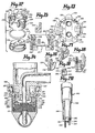
- Figure 1 is an exploded pictorial view of an implantable T-shaped blood access de7ice including the insert and septum of the present invention.
- Figure 2 is a top plan view of the implantable T-shaped assembly with the inventive insert and septum included therein;
- Figure 3 is a side view of the implantable blood access device, including an optional exterior coating of porous titanium, with pats cut away showing the insert and septum in place within the device stem;
- Figure 4 is a plan view of the top side of the septum of the present disclosure;
- Figure 5 is a side section view along lines 5-5 of Figure 4;
- Figure 6 is a plan view of the bottom interior facing side of the septum of the present disclosure;
- Figure 7 is a top plan view of the insert with septum prior to insertion into the blood access device;
- Figure 8 is a side sectional view of the insert and septum taken along the lines 8-8 of Figure 7;
- Figure 9 is a side elevational view of an insertion rod for use with the device of Figures 1 through 8;
- Figure 10 is a top plan view of the insertion rod;
- Figure 11 is a bottom plan view of the insertion rod;
- Figure 12 is an exploded view of a preferred insert and septum assembly;
- Figure 13 is a top plan view of the preferred insert and septum assembly;
- Figure 14 is an end elevational view of a preferred insert assembly in place within a blood access device with a cooperating needle assembly inserted therethrough;
- Figure 15 is a cut-away view of the preferred insert with part of a removal tool shown in association therewith;
- Figures 16, 17 and 18 show cut away portions of the insert assembly with alternative removal means and removal tools associated therewith;
- Figure 19 is an external side elevational view of a keyhole removel means element as shown in Figure 18; and
- Figure 20 is a pictorial view of a modified insertion tool for the preferred insert of Figures 12-15.
- Referring to the drawings, there will be seen in Figure 1 an implantable blood access device which includes a T-shaped unitary tubular body generally designated 10 having a stem portion 11 and a straight
body tube portion 12.Body 10 is formed as a unitary body from a biologically compatible material such as titanium. Thebody 10 may be coated with pyrolytic carbon to enhance biocompatibility. To aid in accomplishing tissue in growth onto the portion of the stem below the skin, the surfaces ofbody 10 below the skin may have a matte or porous finish. Alternatively, the surfaces below the skin may be coated with a porous material such as polyethyleneberephthalate to promote tissue in growth. The embodiment ofbody 10 shown in Figure 3 includes optionalporous titanium layer 14 on its exterior below the skin surfaces. - The implanted device may be placed directly in a blood vessel. In such a case, the blood vessel would be slit longitudinally for sufficient distance for the
device 10 to be inserted and the vessel drawn around the device overridges 13 ontubular portion 12 and sutured into place. Alter-. natively, polymeric tubing, preferably tapered tubing, may be used as an intermediary connection between the ends oftubular portion 12 and the blood vessel. - As can be seen in Figure 3,
body 10 is formed with aninternal extension 15 which substantially provides a separation of the internal cavity of T-stem 11 from the internal chamber ofportion 12 except for theopening 16. Member l5 provides a support surface of anelastomeric septum member 18 through which a needle or needle pair may gain access to the blood stream. - The septum is held in place under sealing pressure by a
novel insert member 22 which serves both as retaining means and as a pressure plate for the septum. -
Insert 22 is a generally tubular member which fits closely into the irterior cavity of stem 11. The upper edge of the insert is provided with a pair of outwardly extendingtabs 24 on opposite sides thereof. The walls ofinsert 22 are provided withelongated notches 26 therethrough on both sides oftabs 24.Notches 26 permit the insert wallportion containing tabs 24 to flex inwardly when inward pressure is applied to the tabs. Theundersurfaces 28 oftabs 24 are tapered so that when the insert is placed into the interior cavity of stem 11 and downard pressure applied to the insert, the insert wallportions containing tabs 24 will flex inwardly permitting the tabs to pass below the upper lip of stem 11. The tabs snap into circumferential groove 30 of the interior surface of stem 11. - The lower portion of the insert body is provided with an integral shelf member or
pressure plate 32 which extends across the interior cavity ofinsert 22, dividing the interior cavity ofinsert 22 into anupper chamber 33 and alower chamber 34.Plate 32 defines a pair ofholes 35 therethrough for which a needle pair may pass into the blood stream through the septum. As shown in Figure 8, the upper portion ofseptum 18 fits snugly into thelower insert chamber 34. - As shown in Figures 4, 5 and 6,
septum 18 is a modified version of the septum described in co-pending application Serial No. 209,058. The septum which is preferably made of a silicone elastomer, has a generally circular shape with a pair ofslits 37 extending from opposite sides toward the center thereof. An unslitcentral portion 38 holds the septum together. A pair ofsemispherical depressions 39 in the top of the septum centered on the slits and spaced correspondingly withholes 35 inflate 32 provide entry points for a needle or other cannulae. The bottom of the septum is provided with anelongated oval depression 40 which provides further relief for the septum when the needles are inserted therethrough.Circumferential groove 42 in the sides of the septum carries an elastomeric band or O-ring 44 whose interior diameter at rest is less than the diameter ofgroove 42.Ring 44 provides inwardly directed circumferential force to hold the septum together and to maintain the slits in sealed relationship against each other or around an inserted needle. Unlike the septum of application Serial No. 209,058, however, the septum portions above and belowgroove 42, respectively, do not have the same dimensions. Whereas,, the upper portion ofseptum 18 is sized to fit snugly within thecavity 34 of theinsert member 22, the lower portion ofseptum 18 in the rest state is slightly larger than that ofinsert member 22. The lower portion ofseptum 18 conforms generally with the interior configuration of the lower stem cavity so that, when the septum is inserted in the cavity of stem 11 and held there under pressure applied byplate 32 ofinsert member 22, the lower portion ofseptum 18 seals against the interior wall of stem 11 and against supportingsurface 15. - Since the septum of the present invention is preferably circular, some means to assure proper alingment of septum slits 37 with insert holes 35 is desirable. This may be done by providing the insert with an off-
center pin 50 which projects intoinsert chamber 34 fromplate 32. A correspondinghole 52 inseptum 18 which extends partway through the septum from the top thereof, accommodatespin 50, aligning the septum slits with the insert holes. - To assure that the needle slits are aligned with the longitudinal access of the body 10, the upper edge of
insert 22 may be provided with semi-circular outwardly extendinglugs 56 which fit into correspondingly shapeddepressions 58 in the upper interior wall of stem 11. - Insertion of the septum and insert is a single step operation. The septum is placed in lower .
chamber 34 ofinsert 22 as shown in Figure 8. A rod-like insertion tool such asmember 60 which is shown in Figures 9-11 is placed in theupper chamber 33 of the insert member. The insert and septum assembly is placed in the cavity of stem 11 withlugs 56 in alignment withdepressions 58.Body 10 is held by means of the portion of stem 11 extending above the skin surface, while downward pressure is exerted onplate 32 by means ofrod 60.Rod 60 has twolower protrusions 61 which fit intoholes 35 ofplate 32 to maintain the rod in the center of the insert.Rod 60 may also be provided with two short, round ended pins, protruding downward fromprotrusions 61 which extend into the septum slits 37 to engage and hold the insert/septum assembly during insertion. The diameter ofrod 60 is less than the interior diameter ofchamber 33 permitting the portions of the insertwall containing tabs 24 to be flexed inwardly. The downward pressure onrod 60 causes the insert wallportions containing tabs 24 to flex inward and allows the septum and insert assembly to be pushed into the stem cavity untiltabs 24 engagestem groove 30. The depth ofstem groove 30 is set so as to maintain the septum in the stem cavity under slight compressionto assure proper sealing. - For convenient removal of the septum and insert, a pair of
grooves 62 are provided in the upper lip of stem 11. These grooves are aligned with a central portion oftabs 24 when the insert and septum are in place within the stem cavity. The grooves extend below the upper edge of the insert member so that access totabs 24 may be achieved by a crimping tool such as a forceps. To remove the insert and septum, thetabs 24 are squeezed inwardly and the insert pulled out of the stem cavity by means of such a tool. Because the upper portion ofseptum 18 is held snugly withincavity 34 of the insert member, the septum comes out with the insert in a single operation. - Figures 12-20 show details of preferred embodiments of the present invention. The preferred inserts are designed so that they may be conveniently removed from the stem of a percutaneous device which does not include the
notches 62, shown in Figures 2 and 3, in the upper lip of the stem. The preferred inserts also utilize improved alingment means for orienting the septum in the insert and for aligning the insert in the percutaneous device stem. - The preferred insert structure is designated by the numeral 122. The device includes a pair of diametrically opposed outwardly extending locking
tabs 124 near the upper edge thereof andelongated slots 126 through the walls of the upper chamber. As with the embodiment of Figures 1-8, theupper chamber 133 is divided from the lower chamber 134-by an integralpressure plate member 132, including a pair ofneedle openings 135 therethrough. -
Slots 126 define aportion 138 of the walls of the upper chamber from which lockingtabs 124 extend outwardly.Wall portions 138 also include a pair ofremoval tabs 140, which extend inwardly to the cavity of theupper chamber 133. Theseremoval tabs 140 includegrooves 142 on the underside thereof which may be engaged by a forceps which includes hook-shaped ends 144 as shown in Figure 15. To remove the insert, the forceps is inserted into the cavity ofchamber 133 and theends 144 thereof brought into engagement withgrooves 142 of the removal tabs. By squeezing the forceps together, theinsert wall portions 138 will be flexed inwardly, disengaging the lockingtabs 124 from the groove in the side wall of the percutaneous device, thereby permitting removal of the insert and septum assembly. - Alternative removal means are shown in Figures 16-19. The alternative of Figure 16 includes an inwardly extending removal tab 145. Tabs 145, rather than having a groove in the underside thereof, merely have a
hole 146 extending through the tab. The ends of a forceps 147 are passed through the hole and squeezed together to disengagetabs 124 from the percutaneous device stem. The forceps are preferably provided with an enlarged disk-like tip portion 148 which can engage the underside of tab 145 during the removal procedure so that the insert. and septum assembly may be easily lifted from the stem of the percutaneous device. - Figure 17 shows another alternative removal means structure. In Figure 17, rather than utilizing inwardly extending tabs, the
side wall portions 138 abovetab member 124 include ahole 150 therethrough which is enlarged on the outside of the wall, leaving a thininner wall portion 152 which may be engaged by hooked forceps ends 154 permitting thewall portion 138 to be flexed inwardly and the insert lifted from the stem of the percutaneous device. - Figures,18 and 19 show a keyhole slot removal means similar to that of Figure 17.
Wall portions 138 include ahole 160 therethrough with anarrow slot 162 extending upwardly. A wider slot, the width ofhole 160, extends upwardly, concentric withslot 162.Slot 163 extends only part way throughwall portion 138 from the outside thereof. This leaves anarrow shoulder portion 164 ofwall 138 which may be engaged by a modified forceps tool. The modified forceps tool includes L-shaped ends 167 having an enlargeddisk end portion 168 which may pass throughhole 160 and engage the thinslot wall portion 164, so as to permitwall 138 to be flexed inwardly and the insert to be lifted from the percutaneous device. - Structures embodying one of the removal means shown in Figures 15-19 are preferred to that of Figures 1-8 because it is not necessary to provide the stem of the percutaneous device with
slots 62 in the upper lip thereof. This, in turn, permits better sealing of snap-type cap structures which are typically placed on the device when not in use to protect the interior of the stem from contamination and to retain a sterilizing fluid within the stem cavity. - The invention device may also be provided with three
alignment lugs 170 which fit into corresponding depressions in the upper interior wall of stem 11. The use of a three-lug alignment structure permits additional latitude in manufacturing tolerances of the insert while achieving the same alignment accuracy. In blood access applications where careful alignment of the needle openings with respect to the blood flow through the arms of the device is desirable. it is preferred that the alignment lugs 56 or 170 touch the interior side walls of the stem cavity of the blood access device with slight compression.This positive contact between the alignment lugs and the interior wall of the stem cavity provides an additional incremental improvement in the alignment of the insert within the stem cavity. - To accurately align the septum in the inserts so that the septum slits are always accurately oriented with respect to
holes 135 andintegral pressure plate 132, theinsert member 122 preferably includes anelongated slot 171 in the bottom ofpressure plate 132 and extending through the side walls of the lower chamber of the insert, as is shown in Figure 15. The upper portion of theseptum 172 includes anelongated ridge 174, shown in Figures 12 and 14, which fits intoslot 171 so as to properly orient the septum in the insert. - In the preferred structure, the septum will be adhesively bonded to the insert so as to assure that orientation is maintained during insertion and to assure that the septum and insert come out of the stem of the percutaneous device as a single unit. A medical grade silicone adhesive. may typically be used to bond the upper surface of the
septum 172 to the insert. To facilitate such adhesive bonding,pressure plate 132 may be provided withholes 180 therethrough in addition to the needle holes 135. As shown in Figure 14,beads 182 of silicone adhesive may be placed inholes 180 so as to contact theseptum 172 and overlap the upper surface ofpressure plate 132. The septum becomes securely bonded to theinsert member 122 when theadhesive beads 182 set up. - As indicated in Figure 14, the
stem 186 of the percutaneous device into which the insert/ septum assembly of the present invention is placed preferably includes two excutaneouscircumferential ridges Ridge 187 forms a lip on the top of the stem over which a needle orcannulae assembly 189 may be snapped. When the needle assembly is removed, a cap member, not shown, may be snapped overlip ridge 187. Thelower ridge 188 provides a gripping surface around which a forceps, such as disclosed in co-pending application Serial Number 209,058, may be clamped to hold the device securely during insertion and removal of the insert/septum assembly. - The insert structures of the present invention may be manufactured of a body compatible metal. Alternatively, they may be manufactured by injection molding of an appropriate plastic, such as polycarbonate or polysulfone. A reinforcement, such as glass, mineral or carbon, may be used in the plastic composition to improve its flexural and hardness characteristics.
- The preferred insert of Figures 12-15 requires a slightly modified insertion tool from that of Figures 9-11. The modified tool is shown in Figure 20 and generally designated by the numeral 190. The tool of Figure 20 includes
protrusions 192 on the lower surface thereof for engaging the tool inholes 35 so as to properly center the tool in the upper chamber of the stem.Pins 194 extend downwardly fromprotrusions 192 for engagement with the septum slits to hold the septum/insert assembly during the insertion step. The modified insertion tool includesslots 196 in the sides thereof which permit the tool to be passed between removal lugs 140. Theinsertion member 190 may also be provided with an enlarged upper section for convenient manipulation.Shoulder 198 between the upper and lower sections of the insertion tool is spaced so that the shoulder contacts the upper lip of the stem of the percutaneous device when insertion of the insert/septum assembly is complete. - It will be readily seen that various modifications from the specific structures disclosed herein may be made without departing from the present invention.
Claims (15)
Applications Claiming Priority (2)
| Application Number | Priority Date | Filing Date | Title |
|---|---|---|---|
| US350574 | 1982-02-22 | ||
| US06/350,574 US4405320A (en) | 1982-02-22 | 1982-02-22 | Septum retaining means for percutaneous device |
Publications (3)
| Publication Number | Publication Date |
|---|---|
| EP0087189A2 true EP0087189A2 (en) | 1983-08-31 |
| EP0087189A3 EP0087189A3 (en) | 1983-11-16 |
| EP0087189B1 EP0087189B1 (en) | 1986-04-02 |
Family
ID=23377311
Family Applications (1)
| Application Number | Title | Priority Date | Filing Date |
|---|---|---|---|
| EP83200214A Expired EP0087189B1 (en) | 1982-02-22 | 1983-02-10 | Septum retaining means for percutaneous device |
Country Status (8)
| Country | Link |
|---|---|
| US (1) | US4405320A (en) |
| EP (1) | EP0087189B1 (en) |
| JP (1) | JPS58155847A (en) |
| AU (1) | AU562617B2 (en) |
| CA (1) | CA1178154A (en) |
| DE (1) | DE3362753D1 (en) |
| MX (1) | MX154514A (en) |
| MY (1) | MY8700845A (en) |
Cited By (2)
| Publication number | Priority date | Publication date | Assignee | Title |
|---|---|---|---|---|
| EP0318358A1 (en) * | 1987-11-23 | 1989-05-31 | Société dite : LG MEDICAL S.A. | Implantable device to access to the circulatory system and his different elements to use it |
| LT3410B (en) | 1991-01-30 | 1995-09-25 | Hemapure Ab | Device for the connection offluid conduits for medical purposes |
Families Citing this family (35)
| Publication number | Priority date | Publication date | Assignee | Title |
|---|---|---|---|---|
| US4496350A (en) * | 1980-04-08 | 1985-01-29 | Renal Systems, Inc. | Blood access device |
| US4581020A (en) * | 1983-07-18 | 1986-04-08 | Trimedyne, Inc. | Medication delivery device and system for percutaneous administration of medication |
| US4781693A (en) * | 1983-09-02 | 1988-11-01 | Minntech Corporation | Insulin dispenser for peritoneal cavity |
| US4639247A (en) * | 1984-11-02 | 1987-01-27 | Carbomedics, Inc. | Percutaneous access device |
| US4634432A (en) * | 1985-05-13 | 1987-01-06 | Nuri Kocak | Introducer sheath assembly |
| US4645494A (en) * | 1985-10-22 | 1987-02-24 | Renal Systems, Inc. | Peritoneal device system |
| US4886502A (en) * | 1986-12-09 | 1989-12-12 | Thermedics, Inc. | Peritoneal access catheter |
| US5178607A (en) * | 1987-07-31 | 1993-01-12 | Lynn Lawrence A | Blood aspiration assembly septum and blunt needle aspirator |
| WO1989006553A2 (en) | 1988-01-25 | 1989-07-27 | Baxter International Inc. | Pre-slit injection site and tapered cannula |
| US5964785A (en) * | 1988-01-25 | 1999-10-12 | Baxter International Inc. | Bayonet look cannula for pre-slit y-site |
| CA1330412C (en) | 1988-07-08 | 1994-06-28 | Steven C. Jepson | Pre-slit injection site and tapered cannula |
| MX173202B (en) | 1989-03-17 | 1994-02-08 | Baxter Int | PLACE TO PLACE INJECTIONS WITH PRE-CUT AND SHARP CANNULA |
| US5171216A (en) * | 1989-08-28 | 1992-12-15 | Thermedics, Inc. | Multi-lumen catheter coupling |
| US5281199A (en) * | 1990-03-01 | 1994-01-25 | Michigan Transtech Corporation | Implantable access devices |
| US5350360A (en) * | 1990-03-01 | 1994-09-27 | Michigan Transtech Corporation | Implantable access devices |
| US5180365A (en) * | 1990-03-01 | 1993-01-19 | Ensminger William D | Implantable infusion device |
| US5226879A (en) * | 1990-03-01 | 1993-07-13 | William D. Ensminger | Implantable access device |
| US5356381A (en) * | 1990-03-01 | 1994-10-18 | Ensminger William D | Implantable access devices |
| US5263930A (en) * | 1990-03-01 | 1993-11-23 | William D. Ensminger | Implantable access devices |
| US5057084A (en) * | 1990-03-01 | 1991-10-15 | The Regents Of The University Of Michigan | Implantable infusion device |
| US5352204A (en) * | 1990-03-01 | 1994-10-04 | Ensminger William D | Implantable access devices |
| US5554117A (en) * | 1990-03-01 | 1996-09-10 | Michigan Transtech Corporation | Implantable access devices |
| US5108413A (en) * | 1990-12-20 | 1992-04-28 | Moyers Robert E | Dilator for opening the lumen of a tubular organ |
| US5776125A (en) * | 1991-07-30 | 1998-07-07 | Baxter International Inc. | Needleless vial access device |
| US5399168A (en) * | 1991-08-29 | 1995-03-21 | C. R. Bard, Inc. | Implantable plural fluid cavity port |
| US5360407A (en) * | 1991-08-29 | 1994-11-01 | C. R. Bard, Inc. | Implantable dual access port with tactile ridge for position sensing |
| DE4129782C1 (en) * | 1991-09-07 | 1992-10-08 | Hans Dipl.-Ing. Dr.Med. 3015 Wennigsen De Haindl | |
| US6042569A (en) * | 1994-01-18 | 2000-03-28 | Vasca, Inc. | Subcutaneously implanted cannula and methods for vascular access |
| DE4418910A1 (en) * | 1994-05-31 | 1995-12-07 | Mouhamed Kamal Dr Med Koudaimi | Dialysis port system and diaphragm |
| WO1996036297A1 (en) * | 1995-05-19 | 1996-11-21 | Kanji Inoue | Transplantation instrument, method of bending same and method of transplanting same |
| US5792104A (en) * | 1996-12-10 | 1998-08-11 | Medtronic, Inc. | Dual-reservoir vascular access port |
| US20110288502A1 (en) * | 2010-05-18 | 2011-11-24 | C.R. Bard, Inc. | Reinforced septum for an implantable medical device |
| US9370619B2 (en) | 2009-02-21 | 2016-06-21 | Incumed, Llc | Partially implantable medical devices and delivery/manifold tube for use with same |
| US8202260B2 (en) | 2009-02-21 | 2012-06-19 | Incumed, Llc | Partially implantable medical devices with cartridge movement sensor and associated methods |
| EP2859911A1 (en) | 2013-10-11 | 2015-04-15 | qSTAR Medical SAS | Vascular access port devices with incorporated sensors |
Citations (5)
| Publication number | Priority date | Publication date | Assignee | Title |
|---|---|---|---|---|
| US3276472A (en) * | 1963-12-03 | 1966-10-04 | Medex Inc | Medical valve |
| DE1475706A1 (en) * | 1964-02-13 | 1969-01-16 | Hoover Ltd | Tubular connection unit |
| US4143853A (en) * | 1977-07-14 | 1979-03-13 | Metatech Corporation | Valve for use with a catheter or the like |
| GB2073027A (en) * | 1980-04-08 | 1981-10-14 | Renal Systems | Blood access device |
| FR2493149A1 (en) * | 1980-11-05 | 1982-05-07 | Materiels Annexes Dialyse | DEVICE FOR PROTECTING A CONNECTION TIP BY A DISINFECTANT |
Family Cites Families (6)
| Publication number | Priority date | Publication date | Assignee | Title |
|---|---|---|---|---|
| US4043474A (en) * | 1975-06-09 | 1977-08-23 | American Home Products Corporation | Child resistant closure for a container |
| US4014328A (en) * | 1975-06-23 | 1977-03-29 | Cluff Kenneth C | Blood sampling and infusion chamber |
| US4016884A (en) * | 1975-07-02 | 1977-04-12 | Kwan Gett Clifford S | Atriotomy access device |
| US4092983A (en) * | 1977-01-31 | 1978-06-06 | General Atomic Company | Blood access device |
| DE2754348A1 (en) * | 1977-12-07 | 1979-06-13 | Juergen Berger | OIL DRAIN AND COLLECTOR |
| US4350157A (en) * | 1980-06-03 | 1982-09-21 | Bentley Laboratories | Atraumatic blood access device valve |
-
1982
- 1982-02-22 US US06/350,574 patent/US4405320A/en not_active Expired - Lifetime
- 1982-10-18 CA CA000413681A patent/CA1178154A/en not_active Expired
- 1982-10-28 AU AU89848/82A patent/AU562617B2/en not_active Ceased
-
1983
- 1983-02-10 DE DE8383200214T patent/DE3362753D1/en not_active Expired
- 1983-02-10 EP EP83200214A patent/EP0087189B1/en not_active Expired
- 1983-02-21 MX MX196337A patent/MX154514A/en unknown
- 1983-02-22 JP JP58028412A patent/JPS58155847A/en active Pending
-
1987
- 1987-12-30 MY MY845/87A patent/MY8700845A/en unknown
Patent Citations (5)
| Publication number | Priority date | Publication date | Assignee | Title |
|---|---|---|---|---|
| US3276472A (en) * | 1963-12-03 | 1966-10-04 | Medex Inc | Medical valve |
| DE1475706A1 (en) * | 1964-02-13 | 1969-01-16 | Hoover Ltd | Tubular connection unit |
| US4143853A (en) * | 1977-07-14 | 1979-03-13 | Metatech Corporation | Valve for use with a catheter or the like |
| GB2073027A (en) * | 1980-04-08 | 1981-10-14 | Renal Systems | Blood access device |
| FR2493149A1 (en) * | 1980-11-05 | 1982-05-07 | Materiels Annexes Dialyse | DEVICE FOR PROTECTING A CONNECTION TIP BY A DISINFECTANT |
Cited By (2)
| Publication number | Priority date | Publication date | Assignee | Title |
|---|---|---|---|---|
| EP0318358A1 (en) * | 1987-11-23 | 1989-05-31 | Société dite : LG MEDICAL S.A. | Implantable device to access to the circulatory system and his different elements to use it |
| LT3410B (en) | 1991-01-30 | 1995-09-25 | Hemapure Ab | Device for the connection offluid conduits for medical purposes |
Also Published As
| Publication number | Publication date |
|---|---|
| MY8700845A (en) | 1987-12-31 |
| US4405320A (en) | 1983-09-20 |
| AU562617B2 (en) | 1987-06-18 |
| AU8984882A (en) | 1983-09-01 |
| MX154514A (en) | 1987-09-24 |
| EP0087189B1 (en) | 1986-04-02 |
| EP0087189A3 (en) | 1983-11-16 |
| DE3362753D1 (en) | 1986-05-07 |
| CA1178154A (en) | 1984-11-20 |
| JPS58155847A (en) | 1983-09-16 |
Similar Documents
| Publication | Publication Date | Title |
|---|---|---|
| EP0087189B1 (en) | Septum retaining means for percutaneous device | |
| CA1169731A (en) | Blood access systems | |
| EP0143518B1 (en) | Dispenser for peritoneal cavity | |
| US4417888A (en) | Percutaneous implant | |
| EP0078565B1 (en) | Percutaneous implant | |
| EP0102342B1 (en) | Percutaneous implant for peritoneal dialysis | |
| US5906596A (en) | Percutaneous access device | |
| EP0963216B1 (en) | Longitudinally aligned dual reservoir access port | |
| EP0316096B1 (en) | Universal hemostasis cannula | |
| US4654033A (en) | Device for atraumatic access to the blood circuit | |
| EP0583388B1 (en) | Anchor pad for catheterization system | |
| EP0247590B1 (en) | Catheter-securing member and catheter assembly mounted with the same | |
| US4995856A (en) | Ventriculostomy reservoir | |
| EP0063198B1 (en) | Plug-type percutaneous access device for fluids | |
| EP1676599B1 (en) | Ventriculostomy reservoir | |
| US20050124980A1 (en) | Port stem marking for catheter placement | |
| US20040068233A1 (en) | Venous access device with detachable suture wings | |
| US20060247574A1 (en) | Introducer for a medication infusion set | |
| GB2143133A (en) | Blood access device | |
| JP2002516160A (en) | Luer receiver and fluid transfer method | |
| EP0143517B1 (en) | Implantable parenteral hyperalimentation catheter system | |
| CA1162452A (en) | Blood access device | |
| CA1184820A (en) | Blood access systems | |
| CA1183748A (en) | Percutaneous implant |
Legal Events
| Date | Code | Title | Description |
|---|---|---|---|
| PUAI | Public reference made under article 153(3) epc to a published international application that has entered the european phase |
Free format text: ORIGINAL CODE: 0009012 |
|
| AK | Designated contracting states |
Designated state(s): CH DE FR GB IT LI SE |
|
| PUAL | Search report despatched |
Free format text: ORIGINAL CODE: 0009013 |
|
| AK | Designated contracting states |
Designated state(s): CH DE FR GB IT LI SE |
|
| RHK1 | Main classification (correction) |
Ipc: A61M 1/00 |
|
| 17P | Request for examination filed |
Effective date: 19840112 |
|
| GRAA | (expected) grant |
Free format text: ORIGINAL CODE: 0009210 |
|
| AK | Designated contracting states |
Kind code of ref document: B1 Designated state(s): CH DE FR GB IT LI SE |
|
| PG25 | Lapsed in a contracting state [announced via postgrant information from national office to epo] |
Ref country code: SE Effective date: 19860430 |
|
| REF | Corresponds to: |
Ref document number: 3362753 Country of ref document: DE Date of ref document: 19860507 |
|
| ITF | It: translation for a ep patent filed |
Owner name: SAIC BREVETTI S.R.L. |
|
| ET | Fr: translation filed | ||
| PLBE | No opposition filed within time limit |
Free format text: ORIGINAL CODE: 0009261 |
|
| STAA | Information on the status of an ep patent application or granted ep patent |
Free format text: STATUS: NO OPPOSITION FILED WITHIN TIME LIMIT |
|
| 26N | No opposition filed | ||
| REG | Reference to a national code |
Ref country code: CH Ref legal event code: PFA Free format text: MINNTECH CORPORATION |
|
| REG | Reference to a national code |
Ref country code: FR Ref legal event code: CD |
|
| PGFP | Annual fee paid to national office [announced via postgrant information from national office to epo] |
Ref country code: CH Payment date: 19900116 Year of fee payment: 8 |
|
| PGFP | Annual fee paid to national office [announced via postgrant information from national office to epo] |
Ref country code: DE Payment date: 19900122 Year of fee payment: 8 |
|
| PGFP | Annual fee paid to national office [announced via postgrant information from national office to epo] |
Ref country code: GB Payment date: 19900131 Year of fee payment: 8 |
|
| ITTA | It: last paid annual fee | ||
| PG25 | Lapsed in a contracting state [announced via postgrant information from national office to epo] |
Ref country code: GB Effective date: 19910210 |
|
| PG25 | Lapsed in a contracting state [announced via postgrant information from national office to epo] |
Ref country code: CH Effective date: 19910228 Ref country code: LI Effective date: 19910228 |
|
| PGFP | Annual fee paid to national office [announced via postgrant information from national office to epo] |
Ref country code: FR Payment date: 19910805 Year of fee payment: 9 |
|
| GBPC | Gb: european patent ceased through non-payment of renewal fee | ||
| REG | Reference to a national code |
Ref country code: CH Ref legal event code: PL |
|
| PG25 | Lapsed in a contracting state [announced via postgrant information from national office to epo] |
Ref country code: DE Effective date: 19911101 |
|
| PG25 | Lapsed in a contracting state [announced via postgrant information from national office to epo] |
Ref country code: FR Effective date: 19921030 |
|
| REG | Reference to a national code |
Ref country code: FR Ref legal event code: ST |