EP0087939A2 - Surgical clip applier with serpentine spring clip feeder - Google Patents
Surgical clip applier with serpentine spring clip feeder Download PDFInfo
- Publication number
- EP0087939A2 EP0087939A2 EP83300993A EP83300993A EP0087939A2 EP 0087939 A2 EP0087939 A2 EP 0087939A2 EP 83300993 A EP83300993 A EP 83300993A EP 83300993 A EP83300993 A EP 83300993A EP 0087939 A2 EP0087939 A2 EP 0087939A2
- Authority
- EP
- European Patent Office
- Prior art keywords
- clip
- handle
- clips
- instrument
- jaws
- Prior art date
- Legal status (The legal status is an assumption and is not a legal conclusion. Google has not performed a legal analysis and makes no representation as to the accuracy of the status listed.)
- Granted
Links
- WYTGDNHDOZPMIW-RCBQFDQVSA-N alstonine Natural products C1=CC2=C3C=CC=CC3=NC2=C2N1C[C@H]1[C@H](C)OC=C(C(=O)OC)[C@H]1C2 WYTGDNHDOZPMIW-RCBQFDQVSA-N 0.000 title claims abstract description 11
- 239000000463 material Substances 0.000 claims description 5
- 230000000717 retained effect Effects 0.000 claims description 4
- 230000006835 compression Effects 0.000 claims description 3
- 238000007906 compression Methods 0.000 claims description 3
- 230000007246 mechanism Effects 0.000 abstract description 4
- 210000004204 blood vessel Anatomy 0.000 description 12
- 229910052751 metal Inorganic materials 0.000 description 5
- 239000002184 metal Substances 0.000 description 5
- 239000012815 thermoplastic material Substances 0.000 description 4
- 230000004048 modification Effects 0.000 description 3
- 238000012986 modification Methods 0.000 description 3
- 230000008901 benefit Effects 0.000 description 2
- 210000003811 finger Anatomy 0.000 description 2
- 230000002439 hemostatic effect Effects 0.000 description 2
- 239000004033 plastic Substances 0.000 description 2
- 229910001220 stainless steel Inorganic materials 0.000 description 2
- 239000010935 stainless steel Substances 0.000 description 2
- 210000003813 thumb Anatomy 0.000 description 2
- 206010072170 Skin wound Diseases 0.000 description 1
- 230000009471 action Effects 0.000 description 1
- 230000001154 acute effect Effects 0.000 description 1
- 230000009286 beneficial effect Effects 0.000 description 1
- 238000010276 construction Methods 0.000 description 1
- 230000000694 effects Effects 0.000 description 1
- 239000012530 fluid Substances 0.000 description 1
- 230000005484 gravity Effects 0.000 description 1
- 238000004519 manufacturing process Methods 0.000 description 1
- 230000013011 mating Effects 0.000 description 1
- 239000007769 metal material Substances 0.000 description 1
- 210000000056 organ Anatomy 0.000 description 1
- 229910052715 tantalum Inorganic materials 0.000 description 1
- GUVRBAGPIYLISA-UHFFFAOYSA-N tantalum atom Chemical compound [Ta] GUVRBAGPIYLISA-UHFFFAOYSA-N 0.000 description 1
Images

Classifications
-
- A—HUMAN NECESSITIES
- A61—MEDICAL OR VETERINARY SCIENCE; HYGIENE
- A61B—DIAGNOSIS; SURGERY; IDENTIFICATION
- A61B17/00—Surgical instruments, devices or methods, e.g. tourniquets
- A61B17/12—Surgical instruments, devices or methods, e.g. tourniquets for ligaturing or otherwise compressing tubular parts of the body, e.g. blood vessels, umbilical cord
- A61B17/128—Surgical instruments, devices or methods, e.g. tourniquets for ligaturing or otherwise compressing tubular parts of the body, e.g. blood vessels, umbilical cord for applying or removing clamps or clips
Definitions
- This invention relates to a surgical instrument for repeatedly applying surgical clamps or clips to tissue, blood vessels, and the like.
- Clips have been devised for clamping or strangulating various organs, vessels, and other tissue. Clips have been developed for use specifically in strangulating blood vessels in the human body. Such clips are known as hemostatic or ligating clips. The clips may be fabricated from absorbable or nonabsorbable polymeric materials as well as from metal.
- a ligating clip is typically C-shaped, U-shaped, or V-shaped with two spaced-apart or diverging legs connected together at one end in a manner that permits the clip to be squeezed together so that the legs of the clip may be clamped around the tissue or blood vessel so as to tightly constrict the tissue or blood vessel. This prevents a substantial amount of fluid from passing through the tissue or blood vessel from one side of the closed clip to the other side of the closed clip.
- the clip is made of a material and/or has a configuration that enables the clip, once it has been forced closed, to remain set or latched closed and maintain the closed orientation without outside intervention.
- the clip can be deformed to the closed position.
- the legs may be connected by a resilient hinge portion and the distal ends of the legs may be provided with latch means for holding the legs together in a closed position when the legs of the clip are squeezed together around the tissue or blood vessel.
- Such instruments typically include a magazine or cartridge which may or may not be disposable and which holds a plurality of clips. The clips are supplied from the cartridge to jaws of the instrument one at a time for application to the tissue or blood vessel.
- U.S. Patent No. 3,006,344 discloses an instrument for applying a ligating clip to a blood vessel.
- the clip is formed of flat metal or like stock and has a pair of legs extending outwardly in a generally V-shape.
- the clips are arranged in two parallel grooves in a magazine.
- a slide is positioned in each groove and is urged by a suitable conventional spring to advance the clips along the magazine toward the jaws.
- the clips are arranged in each row with one end of one clip abutting the connecting rear portion of the next adjacent front clip.
- the clips are not nestably arranged with the connecting portion of each clip received between the open legs of the next adjacent clip. Rather, the distal end of one of the legs of one clip abuts the rear connecting portion of the next adjacent clip.
- U.S. Patent No. 3,753,438 discloses an applicator for applying clips to suturing thread during the suturing of skin wounds.
- the clips are carried in a cartridge in the instrument.
- a clip is forced forwardly from the cartridge to a position between the instrument jaws by a slide which is operated by a handle. After the clip is positioned within the jaws, the handles of the instrument are squeezed together to squeeze the clip legs together.
- U.S. Patent No. 2,968,041 discloses a trigger actuated "gun" type of clip applicator wherein a flat, sinuous, stainless steel spring is provided to close the jaws when the trigger is pulled.
- the clips are merely loosely contained in a magazine and slide forward in the applicator under the influence of gravity when the applicator is tilted.
- the instrument could be provided with means for biasing the clips forwardly to the jaws but in a manner that would prevent the front clip from being urged or biased against the tissue. This would avoid imposition of an undesired force on the tissue during application of the clip.
- a preferred embodiment of the present invention is incorporated in a medical instrument for applying clips, including ligating clips made from a thermoplastic material.
- the clips each typically have two legs connected together at one end of the clip and are adapted to assume an initial open or spread-apart configuration at the other end.
- the ligating clips are made from a thermoplastic material and that have first and second legs joined at their proximal ends by a resilient hinge.
- the clip legs are spaced apart at their distal ends and each leg has a latch means at its distal end to engage the other leg of the clip for holding the clip closed in clamping engagement about tissue, such as a blood vessel, when the legs are squeezed together.
- Each clip includes a base extending along at least a portion of the first leg and includes means for being guided, by for being retained by, and for supporting the clip in, the instrument.
- the instrument includes first and second handles mounted together for pivotal movement about a pivot axis. Each handle extends forwardly beyond the pivot axis to form a clip closing jaw. The jaws have opposing clip engaging faces.
- Means associated with the first and second handles is provided for limiting the pivoting movement of the handles to a maximum opening of the jaws.
- the first handle includes a guideway for receiving a plurality of open clips in a single row with the clips arranged in end-to-end relationship with the distal end of the first end of one clip abutting the hinge of the next forwardly adjacent clip.
- the first handle includes a clip retaining means along the guideway for engaging the clip base to retain the clip in sliding engagement with the first handle in the guideway.
- Means is provided on the second handle jaw for engaging the second leg of the front clip in the row of clips when the jaws are at the maximum opening and when the open front clip is positioned between the open jaws whereby discharge of the front clip from the open jaws is prevented.
- a last clip engaging member is disposed within the guideway and is adapted to bear against the last clip in the row of clips.
- a serpentine spring is disposed within the guideway and is adapted to be compressed behind the last clip engaging member for moving the row of clips forwardly along the guideway to the jaws.
- FIG. 6 One type of clip or clamp that may be applied with the instrument of the present invention is shown in Figure 6 and is designated therein generally by the reference numeral 10.
- Two clips 10 are illustrated as being open and aligned end-to-end in a row as they would be positioned in the instrument of the present invention that is described in detail hereinafter.
- the clip 10 is seen to be formed with two legs or leg segments 11 and 12 connected at the proximal ends thereof by a hinge, a hinge portion, or a hinge section 13.
- the leg segment 12 terminates at the distal end thereof in a hook member 14 having an inner face 15 substantially parallel to an inner face 18 of the leg segment 12 and forming an acute angle with an end face 17.
- the leg segment 11 terminates at the distal end in an end face 19 which forms an obtuse angle with an inner face 16 of the leg segment 11. Additionally, the leg segment 11 is squared off at a face 25 to form a substantially right angle with a bottom face 20.
- the length and width of the inner faces 16 and 18 are substantially equal and the face 15 of the hook member 14 is spaced from the inner face 18 of the leg segment 12 by a distance corresponding to the thickness of the leg segment 11 between the planes of the inner face 16 and the bottom face 20.
- the hook member 14 is deflected by the end face 19 of the leg segment 11 until the distal end of the leg segment 11 snaps under the hook member 14 and is thereby locked in place.
- the end face 17 of the hook member 14 and the end face 19 of the leg segment 11 are angled as illustrated in Figure 6 to facilitate the passage of the hook member 14 past the leg segment 11 during clip closure.
- the surfaces of the inner faces 16 and 18 may be smooth as illustrated in Figure 6, or may be provided with ridges or grooves to increase vessel holding power.
- the leg segment 12 may also be undercut at the juncture of the hook member 14 and the inner face 18 as illustrated in Figure 6 to increase the deflectability of the hook member 14 and increase the space between the hook member 14 and the leg segment 12. This compensates for any inward deflection of the hooked member 14 during closure which might reduce the clearance between the surfaces 15 and 18 and otherwise interfere with the latching of the clip.
- the clip 10 also has a novel base 45 extending along a portion of either one of the two legs, such as the first leg 11 as illustrated.
- the base 45 terminates in a front face 47 short of the distal end of the first leg 11 whereby an open recess is defined adjacent the front face 47 and below the first leg 11.
- the recess provides clearance for latching the hook member 14.
- Flanges 48 are provided on a portion of the base 45.
- the flanges 48 extend rearwardly from a front face 47 and terminate short of the first leg proximal end.
- the flanges 48 extend laterally outwardly beyond both sides of the first leg 11 to function as guide means for engaging portions of the instrument as will be explained in detail hereinafter.
- the portion of the base that extends rearwardly from the flanges 48 to the proximal end of the clip first leg 11 has a width not greater than the width of the first leg 11.
- the rear end of clip 10, including the hinge section 13 and the back of the base 45, defines a flat surface 44.
- the first leg front face 25 of one clip can abut the rear surface 44 of the next forwardly adjacent clip when the clips are open and arranged end-to-end in a row.
- FIG. 7 A second form of a ligating clip that may be used with the instrument of the present invention is illustrated in Figure 7 and is designated generally therein by reference numeral 10'.
- Two clips 10' are illustrated as being opened and aligned end-to-end in a row as they would be positioned in the instrument of the present invention that is described in detail hereinafter.
- Each clip 10' has a basic structure substantially similar to that of the clip 10 described above with reference to Figure 6, except for the base portion 46 of clip 10' which is different than the base 45 of the clip 10.
- the features of clip 10', other than the base 46, are substantially identical in configuration and function to the features of clip 10 illustrated in Figure 6. Accordingly, the structural features of clip 10' of Figure 7 that are identical to structural features of clip 10 of Figure 6 are designated by the same reference numerals used in Figure 6 for clip 10, but with the addition of a prime mark following each such reference numeral.
- the base 46 of clip 10' extends rearwardly along the length of the first leg 11' to the end of the first leg 11'.
- the base 46 serves to support the clip in the instrument of the present invention that may be used to apply the clip 10' and which is described in detail hereinafter.
- the base 46 also serves for being engaged by and for being guided by the instrument.
- the base 46 terminates short of the distal end of the first leg 11' to define a recess for accommodating the latching of the hook member 14' of the second leg 12'.
- the base 46 has a generally right rectangular parallelpiped or prism configuration with portions 49 extending laterally outwardly from the first leg 11' on each side of the first leg.
- the portions 49 of the base 46 extending laterally outwardly function as a guide means for engaging portions of the clip applier instrument.
- Each of the above-described two novel clip structures when fabricated from a suitable thermoplastic material, is biased to the open position by the resilient hinge portion.
- the legs of the clip may be deflected inwardly toward one another a small amount in a magazine, guide channel, or jaw structure of a clip applier instrument. Owing to the resilience of the hinge joining the two legs, the two legs will exert a force outwardly against the magazine, channel, or jaw structure to thereby provide a small friction holding force which may serve to help maintain the clip in the proper orientation or position within the instrument.
- the resilient hinge plastic clip is in contrast with conventional ligating clips fabricated from relatively small diameter wire-like stock.
- Such metal clips can tolerate substantially no inward deflection of the legs without undergoing permanent deformation. Consequently, such metal clips exhibit no useful degree of resiliency and thus do not have the same inherent capability for providing the frictional holding force that is found in the above-described type of plastic clip.
- FIG 1 illustrates one form of an instrument 50 of the present invention for applying clips, such as the ligating clips 10 and 10' described above with reference to Figures 6 and 7.
- the instrument 50 includes a first scissors-type handle 51 and a second scissors-type handle 52 that are mounted together for pivotal movement, about a pivot axis defined by a pin or a shaft 54, between an open position and a closed position.
- the shaft 54 has a head 56 on either side of the second handle 52 as best illustrated in Figures 2 and 4.
- the first handle 51 extends rearwardly of the pivot shaft 54 and includes a finger or thumb ring 56.
- the second handle 52 extends rearwardly of the pivot shaft 54 and includes a finger or thumb ring 58.
- the first handle 51 extends forwardly of the pivot shaft 54 and defines a lower jaw 61.
- the second handle 52 extends forwardly of the pivot shaft 54 and defines an upper jaw 62.
- the second handle 52 includes a pair of spaced-apart sidewalls 64 and 66 which extend for a portion of the length of the second handle 52 and which merge above the pivot shaft 54 to form the upper jaw 62.
- a substantial portion of the length of each of the handles 51 and 52 lies in a common plane.
- the jaws 61 and 62 curve laterally outwardly.
- biasing means is provided for biasing the first and second handles 51 and 52, respectively, to a fully open position as illustrated in solid line in Figure 1.
- the biasing means is designated generally by reference numeral 70 in Figures 1 and 3 and is preferably a helical compression spring disposed between the first and second handles 51 and 52, respectively, rearwardly of the pivot shaft 54.
- the spring 70 biases the handles 51 and 52 apart, and hence the jaws 61 and 62, to a maximum opening as determined by a means associated with the first and second handles for limiting the pivoting movement.
- the means associated with the first and second handles for limiting the pivoting movement of the handles includes an abutment surface 72 on the first handle 51 and an engaging surface 74 on the second handle 52.
- the second handle-engaging surface 74 is oriented at an angle relative to the first handle abutment surface 72 when the handles 51 and 52 are closed.
- the surface 74 is oriented substantially parallel with, and is in contact with, the first handle abutment surface 72.
- the first handle 51 includes two mating pieces or halves 51A and 51B which are secured together by a suitable conventional means, such as by screws or snap-fit connections (not illustrated).
- the first handle halves 51A and 51B define a chamber, channel, or guideway 76 as best illustrated in Figures 1 and 3.
- the upper portion of the guideway 76 has a generally rectangular cross section that communicates along its bottom with a lower channel 78 that is wider than the upper part of the guideway 76.
- the guideway 76 receives a plurality of the open clips (e.g., clip 10 of Figure 6) in end-to-end relationship with the distal end of the first leg of one clip abutting the leg connection end or hinge of the next forwardly adjacent clip.
- the clips 10 are moved forwardly along the guideway 76 by means described hereinafter in detail.
- the lower or bottom channel 78 receives the clip base 45 and base flanges 48 of each clip 10.
- the interior portions of the handle 51 that define the upper part of the guideway 76 above the lower channel 78 project inwardly over the lower channel 78 and function as a clip retaining means along the guideway for engaging the clip flanges 48 to retain the clips in sliding engagement with the first handle 51 in the guideway 76.
- the guideway 76 is defined at the rear end of the handle 51 by a rear wall 75.
- the upper sides of the first handle 51 that define the guideway 76 do not extend forwardly beyond the handle pivot shaft 54.
- the opening into the channel 78 is defined by inwardly projecting flanges 77 on either side as best illustrated in Figure 4. These flanges 77 thus continue to retain the clips within the channel 78 forward of the pivot shaft 54.
- a last clip engaging member 80 is disposed within the guideway 76 and is adapted to bear against the last clip in the row of clips.
- the last clip engaging member 80 defines a bearing surface 82 conforming to the exterior, rearwardly facing surfaces of at least a portion of the second leg and hinge of the last clip when the last clip is in the open position as illustrated in Figure 1.
- the rear surface 44 of the clip 10, as well as the exterior surface of the leg 12 of the clip 10 would be engaged by the member 80.
- a flat, serpentine spring 84 is disposed within the guideway 76, against rear wall 75, and is adapted to be compressed behind the last clip engaging member 80 for moving the row of clips forwardly along the guideway 76 to the jaws 61 and 62.
- the flat, serpentine spring 84 has a relatively high compression ratio and one end may be secured to, or at least bear against, the last clip engaging member 80.
- the serpentine spring 84 generally occupying a volume in the shape of a right rectangular prism, is conveniently received and captured in the clip guideway 76, thus eliminating the necessity for providing suitable guiding structures that might be required if another type of spring were used.
- the serpentine spring 84 is shown in a compressed state in Figure 1.
- Figure 5A is an enlarged view of the serpentine spring 84 also in the compressed state.
- the spring 84 may be made from a suitable flat spring stock (e.g., ASTM A228-47) having a thickness of about 0.003 inch.
- a suitable flat spring stock e.g., ASTM A228-47
- Such a spring 84 preferably has a closed pitch of 0.036 inch and an open pitch of 0.385 inch.
- the height of the spring is 0.187 inch
- the radius at each bend is about 0.015 inch
- the angle between the two diverging legs at each bend is about 90 degrees.
- Figure 5B illustrates an alternate embodiment of a spring 84', shown in an open (uncompressed) state, which functions in a manner similar to the spring 84 illustrated in Figure 5A.
- Each pair of diverging legs in the spring 84 1 is joined by a circular arc bend 85'.
- the bend defines an arc 85' greater than 180 degrees but the legs diverge from the arc at an included angle of less than 90°.
- first handle half 51A and the first handle half 51B each define a bore 88.
- the bores 88 of the first handle halves 51A and 51B are aligned on a common longitudinal axis and each bore 88 extends through the handle half from the exterior of the handle to the guideway 76.
- the last clip engaging member 80 defines a transverse bore 90 (Figure 1) that can be aligned with the first handle bores 88 by locating the last clip engaging member 80 in the guideway 76 as illustrated in Figure 1 wherein the spring 84 is substantially compressed. With the member 80 at this position, a pin 92 can be at least temporarily disposed through the first handle bores 88 and through the last clip engaging member bore 90 so as to lock the last clip engaging member 80 at that position. This permits the portion of the guideway 76 that is forward of the last clip engaging member 80 to be loaded with a plurality of the open clips 10.
- the clips 10 may be loaded into the instrument 50 by pushing the clips 10 rearwardly through the open jaws.
- the second leg of each open clip will be temporarily deflected toward the first leg as the clip is forced past the jaws.
- the clips may be loaded into the instrument during the initial fabrication of the instrument before the two first handle halves 51A and 51B are secured together.
- the instrument can be designed for easy disassembly (by removing the pivot shaft 54, removing the first handle 51 from the second handle 52, and by then separating the first handle halves 51A and 51B). This would permit loading of the clips into the disassembled instrument.
- the above-described temporary locking mechanism permits the fully loaded instrument to be stored and/or transported without the spring load being imposed upon the clips 10.
- the pin 92 is removed to permit the spring to establish the forward biasing force on the row of clips in the instrument.
- the second handle upper jaw 62 includes means for engaging the second leg of the front clip in the row of clips when the jaws 61 and 62 are at the maximum opening ( Figure 1) and when the front clip is open and positioned between the open jaws. This prevents discharge of the open front clip from the open jaws.
- the engaging means on the second handle upper jaw 62 includes a downwardly projecting lip 94 as best illustrated in Figure 1. The lip 94 extends forwardly beyond the distal end of the first handle lower jaw 61 and would overlap the lower jaw 61 if the jaws were closed without a clip between the jaws.
- the lip 94 prevents the front clip from being discharged from the instrument until the front clip is latched closed.
- the front clip is latched closed,_the height of the closed clip is less than the maximum opening of the jaws 61 and 62 so that the closed clip can be discharged from the instrument when the jaws are subsequently opened to release the closed clip.
- the instrument 50 is actuated by closing the handles 51 and 52 to latch closed the front clip about a blood vessel or other tissue. Subsequent opening of the handles, and withdrawal of the instrument 50 rearwardly, effects a complete discharge of the latched closed clip from the jaws and permits the next rearwardly adjacent clip to be fed forwardly, along with the entire row of clips. With the next clip in position at the jaws and retained by the second jaw lip 94, the instrument 50 is again ready for applying the next clip.
- the last clip engaging member 80 advances into the region between the jaws 61 and 62.
- the last clip engaging member 80 is fabricated from a substantially rigid material and resists any attempt to further close the jaws. This signals the surgeon that all of the clips have been used.
- clips having other suitable configurations may be applied with the instrument.
- metal hemostatic clips with appropriate base structures may be utilized.
- Such clips, while not having resilient hinges, may be formed of tantalum or stainless steel. These clips could be deformed into the closed position and would possess sufficient strength to retain the deformation when clamped about a duct, such as a blood vessel.
Abstract
Description
- This invention relates to a surgical instrument for repeatedly applying surgical clamps or clips to tissue, blood vessels, and the like.
- Clips have been devised for clamping or strangulating various organs, vessels, and other tissue. Clips have been developed for use specifically in strangulating blood vessels in the human body. Such clips are known as hemostatic or ligating clips. The clips may be fabricated from absorbable or nonabsorbable polymeric materials as well as from metal.
- A ligating clip is typically C-shaped, U-shaped, or V-shaped with two spaced-apart or diverging legs connected together at one end in a manner that permits the clip to be squeezed together so that the legs of the clip may be clamped around the tissue or blood vessel so as to tightly constrict the tissue or blood vessel. This prevents a substantial amount of fluid from passing through the tissue or blood vessel from one side of the closed clip to the other side of the closed clip.
- Typically, the clip is made of a material and/or has a configuration that enables the clip, once it has been forced closed, to remain set or latched closed and maintain the closed orientation without outside intervention. For example, if the clip is made from a metal material, the clip can be deformed to the closed position. If the clip is made from a thermoplastic material, the legs may be connected by a resilient hinge portion and the distal ends of the legs may be provided with latch means for holding the legs together in a closed position when the legs of the clip are squeezed together around the tissue or blood vessel.
- A variety of instruments for applying such surgical clips have been developed or proposed in the past. A number of such instruments are discussed and disclosed in British patent application No. 8134724 (Publication No. 2,088,723 A). Such instruments typically include a magazine or cartridge which may or may not be disposable and which holds a plurality of clips. The clips are supplied from the cartridge to jaws of the instrument one at a time for application to the tissue or blood vessel.
- U.S. Patent No. 3,006,344 discloses an instrument for applying a ligating clip to a blood vessel. The clip is formed of flat metal or like stock and has a pair of legs extending outwardly in a generally V-shape. The clips are arranged in two parallel grooves in a magazine. A slide is positioned in each groove and is urged by a suitable conventional spring to advance the clips along the magazine toward the jaws. The clips are arranged in each row with one end of one clip abutting the connecting rear portion of the next adjacent front clip. The clips are not nestably arranged with the connecting portion of each clip received between the open legs of the next adjacent clip. Rather, the distal end of one of the legs of one clip abuts the rear connecting portion of the next adjacent clip.
- U.S. Patent No. 3,753,438 discloses an applicator for applying clips to suturing thread during the suturing of skin wounds. The clips are carried in a cartridge in the instrument. A clip is forced forwardly from the cartridge to a position between the instrument jaws by a slide which is operated by a handle. After the clip is positioned within the jaws, the handles of the instrument are squeezed together to squeeze the clip legs together.
- U.S. Patent No. 2,968,041 discloses a trigger actuated "gun" type of clip applicator wherein a flat, sinuous, stainless steel spring is provided to close the jaws when the trigger is pulled. However, the clips are merely loosely contained in a magazine and slide forward in the applicator under the influence of gravity when the applicator is tilted.
- It would be desirable to provide an improved instrument for accommodating a plurality of clips and for automatically feeding the clips seriatim into jaws where the clips may be compressed about tissue, such as blood vessels and the like.
- It would also be desirable to provide an instrument for applying clips wherein the clips could be arranged in a relatively compact orientation in order to provide an efficient and economical structure.
- It would be beneficial if the instrument could be provided with means for biasing the clips forwardly to the jaws but in a manner that would prevent the front clip from being urged or biased against the tissue. This would avoid imposition of an undesired force on the tissue during application of the clip.
- It would be advantageous to provide such an instrument with means for releasing the forward biasing force at least temporarily to permit reloading of the instrument with new clips.
- It would also be desirable to provide an instrument for applying ligating clips in which the instrument could be actuated by means of scissors-type handles in the same manner as a number of other widely used surgical instruments and in the manner to which surgeons have become accustomed over the years.
- A preferred embodiment of the present invention is incorporated in a medical instrument for applying clips, including ligating clips made from a thermoplastic material. The clips each typically have two legs connected together at one end of the clip and are adapted to assume an initial open or spread-apart configuration at the other end.
- In the preferred embodiment, the ligating clips are made from a thermoplastic material and that have first and second legs joined at their proximal ends by a resilient hinge. The clip legs are spaced apart at their distal ends and each leg has a latch means at its distal end to engage the other leg of the clip for holding the clip closed in clamping engagement about tissue, such as a blood vessel, when the legs are squeezed together.
- Each clip includes a base extending along at least a portion of the first leg and includes means for being guided, by for being retained by, and for supporting the clip in, the instrument.
- The instrument includes first and second handles mounted together for pivotal movement about a pivot axis. Each handle extends forwardly beyond the pivot axis to form a clip closing jaw. The jaws have opposing clip engaging faces.
- Means associated with the first and second handles is provided for limiting the pivoting movement of the handles to a maximum opening of the jaws.
- The first handle includes a guideway for receiving a plurality of open clips in a single row with the clips arranged in end-to-end relationship with the distal end of the first end of one clip abutting the hinge of the next forwardly adjacent clip. The first handle includes a clip retaining means along the guideway for engaging the clip base to retain the clip in sliding engagement with the first handle in the guideway.
- Means is provided on the second handle jaw for engaging the second leg of the front clip in the row of clips when the jaws are at the maximum opening and when the open front clip is positioned between the open jaws whereby discharge of the front clip from the open jaws is prevented.
- A last clip engaging member is disposed within the guideway and is adapted to bear against the last clip in the row of clips.
- A serpentine spring is disposed within the guideway and is adapted to be compressed behind the last clip engaging member for moving the row of clips forwardly along the guideway to the jaws.
- The invention of the apparatus herein described resides in the novel combination, construction, arrangement, and disposition of various component parts and elements incorporated in the apparatus in accordance with the principles of the invention.
- The present invention will be better understood and important features other than those specifically enumerated above will become apparent when consideration is given to the following details and description which, when taken in conjunction with the drawings, describes, discloses, illustrates, and shows a preferred embodiment of the present invention and what is presently believed to be the best mode of practicing the principles of the invention. Other embodiments and modifications may be suggested to those having the benefit of the teachings herein, especially as they fall within the scope and spirit of the sub-joined claims.
- In the accompanying drawings forming part of the specification and in which like numerals are employed to designate like parts throughout the same,
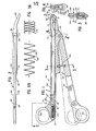
- Figure 1 is a top plan view of the instrument of the present invention with portions of the structure broken away to permit illustration of interior details and showing the instrument fully open in solid lines and showing the closed position of the instrument handles in dashed lines;
- Figure 2 is a side view of the instrument of the present invention as viewed along the planes 2-2 in Figure 1;
- Figure 3 is a cross-sectional view taken generally along the plane 3-3 in Figure 1;
- Figure 4 is an enlarged, fragmentary, cross-sectional view taken generally along the plane 4-4 in Figure 1;
- Figure 5A is a greatly enlarged, fragmentary, side view of one form of a spring for the instrument;
- Figure 5B is a greatly enlarged, fragmentary, side view of another form of a spring for the instrument;
- Figure 6 is a perspective view of a first embodiment of a surgical clip which may be applied to tissue with the instrument of the present invention; and
- Figure 7 is a perspective view of another embodiment of a surgical clip which may be applied with instrument of the present invention.
- This invention may be used in many different forms. The specification and the accompanying drawings discloses a specific embodiment as an example of the use of the invention. The invention is not intended to be limited to the embodiment illustrated, and the scope of the invention will be pointed out in the appended claims.
- The precise shapes and sizes of the components herein described are not essential to the invention unless otherwise indicated. The particular shapes and sizes are shown to best illustrate the principles of the invention.
- A variety of materials may be used for constructing the illustrated instrument as those skilled in the art will appreciate.
- One type of clip or clamp that may be applied with the instrument of the present invention is shown in Figure 6 and is designated therein generally by the
reference numeral 10. Twoclips 10 are illustrated as being open and aligned end-to-end in a row as they would be positioned in the instrument of the present invention that is described in detail hereinafter. - The
clip 10 is seen to be formed with two legs orleg segments 11 and 12 connected at the proximal ends thereof by a hinge, a hinge portion, or ahinge section 13. Theleg segment 12 terminates at the distal end thereof in ahook member 14 having aninner face 15 substantially parallel to aninner face 18 of theleg segment 12 and forming an acute angle with anend face 17. - The leg segment 11 terminates at the distal end in an
end face 19 which forms an obtuse angle with aninner face 16 of the leg segment 11. Additionally, the leg segment 11 is squared off at a face 25 to form a substantially right angle with abottom face 20. - The length and width of the inner faces 16 and 18 are substantially equal and the
face 15 of thehook member 14 is spaced from theinner face 18 of theleg segment 12 by a distance corresponding to the thickness of the leg segment 11 between the planes of theinner face 16 and thebottom face 20. - When the
leg segments 11 and 12 are pivoted about thehinge section 13 to bring the inner faces 18 and 16 into opposition, thehook member 14 is deflected by theend face 19 of the leg segment 11 until the distal end of the leg segment 11 snaps under thehook member 14 and is thereby locked in place. The end face 17 of thehook member 14 and theend face 19 of the leg segment 11 are angled as illustrated in Figure 6 to facilitate the passage of thehook member 14 past the leg segment 11 during clip closure. - The surfaces of the inner faces 16 and 18 may be smooth as illustrated in Figure 6, or may be provided with ridges or grooves to increase vessel holding power. The
leg segment 12 may also be undercut at the juncture of thehook member 14 and theinner face 18 as illustrated in Figure 6 to increase the deflectability of thehook member 14 and increase the space between thehook member 14 and theleg segment 12. This compensates for any inward deflection of the hookedmember 14 during closure which might reduce the clearance between thesurfaces - The
clip 10 also has anovel base 45 extending along a portion of either one of the two legs, such as the first leg 11 as illustrated. Thebase 45 terminates in afront face 47 short of the distal end of the first leg 11 whereby an open recess is defined adjacent thefront face 47 and below the first leg 11. The recess provides clearance for latching thehook member 14. -
Flanges 48 are provided on a portion of thebase 45. Theflanges 48 extend rearwardly from afront face 47 and terminate short of the first leg proximal end. Theflanges 48 extend laterally outwardly beyond both sides of the first leg 11 to function as guide means for engaging portions of the instrument as will be explained in detail hereinafter. The portion of the base that extends rearwardly from theflanges 48 to the proximal end of the clip first leg 11 has a width not greater than the width of the first leg 11. - The rear end of
clip 10, including thehinge section 13 and the back of thebase 45, defines aflat surface 44. Thus, the first leg front face 25 of one clip can abut therear surface 44 of the next forwardly adjacent clip when the clips are open and arranged end-to-end in a row. - A second form of a ligating clip that may be used with the instrument of the present invention is illustrated in Figure 7 and is designated generally therein by reference numeral 10'. Two clips 10' are illustrated as being opened and aligned end-to-end in a row as they would be positioned in the instrument of the present invention that is described in detail hereinafter.
- Each clip 10' has a basic structure substantially similar to that of the
clip 10 described above with reference to Figure 6, except for thebase portion 46 of clip 10' which is different than thebase 45 of theclip 10. The features of clip 10', other than the base 46, are substantially identical in configuration and function to the features ofclip 10 illustrated in Figure 6. Accordingly, the structural features of clip 10' of Figure 7 that are identical to structural features ofclip 10 of Figure 6 are designated by the same reference numerals used in Figure 6 forclip 10, but with the addition of a prime mark following each such reference numeral. - The
base 46 of clip 10' extends rearwardly along the length of the first leg 11' to the end of the first leg 11'. Thebase 46 serves to support the clip in the instrument of the present invention that may be used to apply the clip 10' and which is described in detail hereinafter. The base 46 also serves for being engaged by and for being guided by the instrument. Thebase 46 terminates short of the distal end of the first leg 11' to define a recess for accommodating the latching of the hook member 14' of the second leg 12'. - The
base 46 has a generally right rectangular parallelpiped or prism configuration withportions 49 extending laterally outwardly from the first leg 11' on each side of the first leg. Theportions 49 of the base 46 extending laterally outwardly function as a guide means for engaging portions of the clip applier instrument. - Each of the above-described two novel clip structures, when fabricated from a suitable thermoplastic material, is biased to the open position by the resilient hinge portion. Thus, if force is applied to the distal ends of the legs of the open clip so as to move the legs toward one another (but not far enough to latch the clip), then upon removal of the force from the clip legs, the clip legs will return to the substantially fully open orientation.
- It is believed that this phenomenon can be used to advantage in certain types of clip applier instruments for guiding and holding the clip in the instrument. Specifically, the legs of the clip may be deflected inwardly toward one another a small amount in a magazine, guide channel, or jaw structure of a clip applier instrument. Owing to the resilience of the hinge joining the two legs, the two legs will exert a force outwardly against the magazine, channel, or jaw structure to thereby provide a small friction holding force which may serve to help maintain the clip in the proper orientation or position within the instrument.
- The above-described action of the resilient hinge plastic clip is in contrast with conventional ligating clips fabricated from relatively small diameter wire-like stock. Such metal clips can tolerate substantially no inward deflection of the legs without undergoing permanent deformation. Consequently, such metal clips exhibit no useful degree of resiliency and thus do not have the same inherent capability for providing the frictional holding force that is found in the above-described type of plastic clip.
- Figure 1 illustrates one form of an
instrument 50 of the present invention for applying clips, such as the ligating clips 10 and 10' described above with reference to Figures 6 and 7. Theinstrument 50 includes a first scissors-type handle 51 and a second scissors-type handle 52 that are mounted together for pivotal movement, about a pivot axis defined by a pin or ashaft 54, between an open position and a closed position. Theshaft 54 has ahead 56 on either side of thesecond handle 52 as best illustrated in Figures 2 and 4. - The
first handle 51 extends rearwardly of thepivot shaft 54 and includes a finger orthumb ring 56. Similarly, thesecond handle 52 extends rearwardly of thepivot shaft 54 and includes a finger orthumb ring 58. - The
first handle 51 extends forwardly of thepivot shaft 54 and defines alower jaw 61. Similarly, thesecond handle 52 extends forwardly of thepivot shaft 54 and defines anupper jaw 62. - As best illustrated in Figures 1, 2, and 3, the
second handle 52 includes a pair of spaced-apartsidewalls second handle 52 and which merge above thepivot shaft 54 to form theupper jaw 62. Preferably, as best illustrated in Figure 2, a substantial portion of the length of each of thehandles jaws - Preferably, means is provided for biasing the first and
second handles reference numeral 70 in Figures 1 and 3 and is preferably a helical compression spring disposed between the first andsecond handles pivot shaft 54. - The
spring 70 biases thehandles jaws abutment surface 72 on thefirst handle 51 and an engaging surface 74 on thesecond handle 52. The second handle-engaging surface 74 is oriented at an angle relative to the firsthandle abutment surface 72 when thehandles handle abutment surface 72. - As best illustrated in Figures 2 and 3, the
first handle 51 includes two mating pieces orhalves 51A and 51B which are secured together by a suitable conventional means, such as by screws or snap-fit connections (not illustrated). - The
first handle halves 51A and 51B define a chamber, channel, orguideway 76 as best illustrated in Figures 1 and 3. The upper portion of theguideway 76 has a generally rectangular cross section that communicates along its bottom with alower channel 78 that is wider than the upper part of theguideway 76. Theguideway 76 receives a plurality of the open clips (e.g.,clip 10 of Figure 6) in end-to-end relationship with the distal end of the first leg of one clip abutting the leg connection end or hinge of the next forwardly adjacent clip. Theclips 10 are moved forwardly along theguideway 76 by means described hereinafter in detail. - As best illustrated in Figures 3 and 4, the lower or
bottom channel 78 receives theclip base 45 andbase flanges 48 of eachclip 10. The interior portions of thehandle 51 that define the upper part of theguideway 76 above thelower channel 78 project inwardly over thelower channel 78 and function as a clip retaining means along the guideway for engaging theclip flanges 48 to retain the clips in sliding engagement with thefirst handle 51 in theguideway 76. - As best illustrated in Figure 1, the
guideway 76 is defined at the rear end of thehandle 51 by arear wall 75. The upper sides of thefirst handle 51 that define theguideway 76 do not extend forwardly beyond thehandle pivot shaft 54. In the region of thejaw 61, the opening into thechannel 78 is defined by inwardly projectingflanges 77 on either side as best illustrated in Figure 4. Theseflanges 77 thus continue to retain the clips within thechannel 78 forward of thepivot shaft 54. - The
clips 10 are moved forwardly along theguideway 76 to the region of thejaws guideway 76 and is adapted to bear against the last clip in the row of clips. Preferably, the last clip engaging member 80 defines a bearingsurface 82 conforming to the exterior, rearwardly facing surfaces of at least a portion of the second leg and hinge of the last clip when the last clip is in the open position as illustrated in Figure 1. With reference to Figure 6, therear surface 44 of theclip 10, as well as the exterior surface of theleg 12 of theclip 10, would be engaged by the member 80. - A flat,
serpentine spring 84 is disposed within theguideway 76, againstrear wall 75, and is adapted to be compressed behind the last clip engaging member 80 for moving the row of clips forwardly along theguideway 76 to thejaws serpentine spring 84 has a relatively high compression ratio and one end may be secured to, or at least bear against, the last clip engaging member 80. - The
serpentine spring 84, generally occupying a volume in the shape of a right rectangular prism, is conveniently received and captured in theclip guideway 76, thus eliminating the necessity for providing suitable guiding structures that might be required if another type of spring were used. - The
serpentine spring 84 is shown in a compressed state in Figure 1. Figure 5A is an enlarged view of theserpentine spring 84 also in the compressed state. In a specific embodiment of theinstrument 50, such as illustrated in Figure 1, thespring 84 may be made from a suitable flat spring stock (e.g., ASTM A228-47) having a thickness of about 0.003 inch. Such aspring 84 preferably has a closed pitch of 0.036 inch and an open pitch of 0.385 inch. When thespring 84 is in the open, uncompressed state, the height of the spring is 0.187 inch, the radius at each bend is about 0.015 inch, and the angle between the two diverging legs at each bend is about 90 degrees. - Figure 5B illustrates an alternate embodiment of a spring 84', shown in an open (uncompressed) state, which functions in a manner similar to the
spring 84 illustrated in Figure 5A. Each pair of diverging legs in thespring 841 is joined by a circular arc bend 85'. When the spring 84' is in the open, uncompressed state as illustrated, the bend defines an arc 85' greater than 180 degrees but the legs diverge from the arc at an included angle of less than 90°. - Other suitable serpentine spring designs may be used instead of the designs illustrated in Figures 5A and 5B.
- As best illustrated in Figures 1 and 2, the
first handle half 51A and the first handle half 51B each define abore 88. Thebores 88 of thefirst handle halves 51A and 51B are aligned on a common longitudinal axis and each bore 88 extends through the handle half from the exterior of the handle to theguideway 76. - The last clip engaging member 80 defines a transverse bore 90 (Figure 1) that can be aligned with the first handle bores 88 by locating the last clip engaging member 80 in the
guideway 76 as illustrated in Figure 1 wherein thespring 84 is substantially compressed. With the member 80 at this position, apin 92 can be at least temporarily disposed through the first handle bores 88 and through the last clip engaging member bore 90 so as to lock the last clip engaging member 80 at that position. This permits the portion of theguideway 76 that is forward of the last clip engaging member 80 to be loaded with a plurality of the open clips 10. - The
clips 10 may be loaded into theinstrument 50 by pushing theclips 10 rearwardly through the open jaws. The second leg of each open clip will be temporarily deflected toward the first leg as the clip is forced past the jaws. Alternatively, the clips may be loaded into the instrument during the initial fabrication of the instrument before the twofirst handle halves 51A and 51B are secured together. Also, the instrument can be designed for easy disassembly (by removing thepivot shaft 54, removing thefirst handle 51 from thesecond handle 52, and by then separating thefirst handle halves 51A and 51B). This would permit loading of the clips into the disassembled instrument. - In addition to facilitating the loading of the instrument with open clips, the above-described temporary locking mechanism permits the fully loaded instrument to be stored and/or transported without the spring load being imposed upon the
clips 10. When the instrument is to be used, thepin 92 is removed to permit the spring to establish the forward biasing force on the row of clips in the instrument. - The second handle
upper jaw 62 includes means for engaging the second leg of the front clip in the row of clips when thejaws upper jaw 62 includes a downwardly projectinglip 94 as best illustrated in Figure 1. Thelip 94 extends forwardly beyond the distal end of the first handlelower jaw 61 and would overlap thelower jaw 61 if the jaws were closed without a clip between the jaws. - When the instrument is opened so that the
jaws lip 94 prevents the front clip from being discharged from the instrument until the front clip is latched closed. When the front clip is latched closed,_the height of the closed clip is less than the maximum opening of thejaws - In normal operation, the
instrument 50 is actuated by closing thehandles instrument 50 rearwardly, effects a complete discharge of the latched closed clip from the jaws and permits the next rearwardly adjacent clip to be fed forwardly, along with the entire row of clips. With the next clip in position at the jaws and retained by thesecond jaw lip 94, theinstrument 50 is again ready for applying the next clip. - After all of the
clips 10 have been applied, the last clip engaging member 80 advances into the region between thejaws - Although the
instrument 50 has been described above as being adapted to apply clips having the configuration ofclips 10 and 10' illustrated in Figures 6 and 7, it is to be realized that clips having other suitable configurations may be applied with the instrument. For example, metal hemostatic clips with appropriate base structures may be utilized. Such clips, while not having resilient hinges, may be formed of tantalum or stainless steel. These clips could be deformed into the closed position and would possess sufficient strength to retain the deformation when clamped about a duct, such as a blood vessel. - From the foregoing, it will be observed that numerous variations and modifications may be effected without departing from the true spirit and scope of the novel concept of the invention. It is to be understood that no limitation with respect to the specific apparatus illustrated herein is intended or should be inferred. It is, of course, intended to cover by the appended claims all such modifications as fall within the scope of the claims.
Claims (11)
Applications Claiming Priority (2)
| Application Number | Priority Date | Filing Date | Title |
|---|---|---|---|
| US06/352,833 US4450839A (en) | 1982-02-26 | 1982-02-26 | Surgical clip applier with serpentine spring clip feeder |
| US352833 | 1982-02-26 |
Publications (3)
| Publication Number | Publication Date |
|---|---|
| EP0087939A2 true EP0087939A2 (en) | 1983-09-07 |
| EP0087939A3 EP0087939A3 (en) | 1984-02-08 |
| EP0087939B1 EP0087939B1 (en) | 1986-10-08 |
Family
ID=23386698
Family Applications (1)
| Application Number | Title | Priority Date | Filing Date |
|---|---|---|---|
| EP83300993A Expired EP0087939B1 (en) | 1982-02-26 | 1983-02-25 | Surgical clip applier with serpentine spring clip feeder |
Country Status (10)
| Country | Link |
|---|---|
| US (1) | US4450839A (en) |
| EP (1) | EP0087939B1 (en) |
| JP (1) | JPS58157458A (en) |
| AU (1) | AU557738B2 (en) |
| BR (1) | BR8300935A (en) |
| CA (1) | CA1190825A (en) |
| DE (1) | DE3366657D1 (en) |
| ES (1) | ES520040A0 (en) |
| IN (1) | IN158303B (en) |
| ZA (1) | ZA831314B (en) |
Cited By (2)
| Publication number | Priority date | Publication date | Assignee | Title |
|---|---|---|---|---|
| EP0087941A2 (en) * | 1982-02-26 | 1983-09-07 | Ethicon, Inc. | Ligating clip with flanged base |
| EP0087940A2 (en) * | 1982-02-26 | 1983-09-07 | Ethicon, Inc. | Ligating clip and applier instrument therefor with clip engaging escapement |
Families Citing this family (30)
| Publication number | Priority date | Publication date | Assignee | Title |
|---|---|---|---|---|
| US4527562A (en) * | 1979-06-18 | 1985-07-09 | Ethicon, Inc. | Non-metallic, bio-compatible hemostatic clips |
| US4579118A (en) * | 1983-06-01 | 1986-04-01 | Ethicon, Inc. | Hemostatic clip with penetration means |
| US4616650A (en) * | 1984-07-27 | 1986-10-14 | United States Surgical Corporation | Apparatus for applying surgical clips |
| US4712549A (en) * | 1985-07-01 | 1987-12-15 | Edward Weck & Co. | Automatic hemostatic clip applier |
| US5383881A (en) * | 1989-07-18 | 1995-01-24 | United States Surgical Corporation | Safety device for use with endoscopic instrumentation |
| US5100420A (en) * | 1989-07-18 | 1992-03-31 | United States Surgical Corporation | Apparatus and method for applying surgical clips in laparoscopic or endoscopic procedures |
| US5062846A (en) * | 1989-03-28 | 1991-11-05 | Edward Weck Incorporated | Penetrating plastic ligating clip |
| US5104395A (en) * | 1989-07-03 | 1992-04-14 | Edward Weck Incorporated | Automatic hemostatic clip applicator |
| US5382254A (en) * | 1989-07-18 | 1995-01-17 | United States Surgical Corporation | Actuating handle for surgical instruments |
| US5366134A (en) * | 1991-10-18 | 1994-11-22 | United States Surgical Corporation | Surgical fastening apparatus |
| US5868761A (en) * | 1992-10-09 | 1999-02-09 | United States Surgical Corporation | Surgical clip applier |
| US5300081A (en) * | 1992-10-09 | 1994-04-05 | United States Surgical Corporation | Surgical clip applier having clip advancement control |
| US5382255A (en) * | 1993-01-08 | 1995-01-17 | United States Surgical Corporation | Apparatus and method for assembly of surgical instruments |
| US5858018A (en) * | 1993-08-25 | 1999-01-12 | Apollo Camera, Llc | Low profile tool for applying spring action ligation clips |
| US5607436A (en) * | 1993-10-08 | 1997-03-04 | United States Surgical Corporation | Apparatus for applying surgical clips |
| US5551214A (en) * | 1994-07-20 | 1996-09-03 | Ethicon, Inc. | Ligaclip loading machine and process |
| US5700270A (en) * | 1995-10-20 | 1997-12-23 | United States Surgical Corporation | Surgical clip applier |
| US5833696A (en) * | 1996-10-03 | 1998-11-10 | United States Surgical Corporation | Apparatus for applying surgical clips |
| US5868759A (en) * | 1997-10-10 | 1999-02-09 | United States Surgical Corporation | Surgical clip applier |
| US5951574A (en) * | 1998-10-23 | 1999-09-14 | Ethicon Endo-Surgery, Inc. | Multiple clip applier having a split feeding mechanism |
| US6290575B1 (en) | 1999-03-01 | 2001-09-18 | John I. Shipp | Surgical ligation clip with increased ligating force |
| US6350269B1 (en) | 1999-03-01 | 2002-02-26 | Apollo Camera, L.L.C. | Ligation clip and clip applier |
| US7678125B2 (en) * | 2002-11-12 | 2010-03-16 | Apollo Camera, L.L.C. | Surgical ligation clip |
| US8172870B2 (en) * | 2003-06-09 | 2012-05-08 | Microline Surgical, Inc. | Ligation clip applier |
| US7572266B2 (en) * | 2003-10-21 | 2009-08-11 | Young Wayne P | Clip applier tool having a discharge configuration |
| JP4673393B2 (en) * | 2008-06-05 | 2011-04-20 | 日立オムロンターミナルソリューションズ株式会社 | Paper sheet handling apparatus and method |
| JP2018537168A (en) * | 2015-11-20 | 2018-12-20 | クリップティップ メディカル リミテッド | Surgical clip and its placement control |
| CN106073853B (en) * | 2016-06-20 | 2019-03-08 | 江苏海泽医疗科技发展有限公司 | Semi-automatic medical continuously-applied Clip Applier with biology folder casket |
| USD907987S1 (en) * | 2019-03-07 | 2021-01-19 | Gen-Probe Incorporated | Serpentine retainer spring for a receptacle rack |
| USD907465S1 (en) * | 2019-03-07 | 2021-01-12 | Gen-Probe Incorporated | Serpentine retainer spring for a receptacle rack |
Citations (7)
| Publication number | Priority date | Publication date | Assignee | Title |
|---|---|---|---|---|
| US1452373A (en) * | 1921-10-15 | 1923-04-17 | Gomez Joaquin Sanchez | Surgical ligature and means for applying the same |
| US2968041A (en) * | 1958-09-25 | 1961-01-17 | John F Skold | Applicator for surgical clamps |
| US3006344A (en) * | 1959-02-24 | 1961-10-31 | Isaac J Vogelfanger | Surgical ligator and cutter |
| US3753438A (en) * | 1972-04-25 | 1973-08-21 | E Wood | Suture clip |
| US4179057A (en) * | 1978-11-17 | 1979-12-18 | Senco Products, Inc. | Disposable surgical stapling instrument |
| GB2054027A (en) * | 1979-06-18 | 1981-02-11 | Ethicon Inc | Plastic ligating clips |
| GB2074030A (en) * | 1980-04-22 | 1981-10-28 | Senco Products | Ligating device |
Family Cites Families (11)
| Publication number | Priority date | Publication date | Assignee | Title |
|---|---|---|---|---|
| US2733441A (en) * | 1956-02-07 | white | ||
| US3082426A (en) * | 1960-06-17 | 1963-03-26 | George Oliver Halsted | Surgical stapling device |
| US3780416A (en) * | 1972-07-10 | 1973-12-25 | G Rider | Surgical tubing clip clenching tool |
| US4166466A (en) * | 1976-10-08 | 1979-09-04 | Jarvik Robert K | Repeating hemostatic clip applying instruments and multi-clip cartridges therefor |
| US4226242A (en) * | 1977-09-13 | 1980-10-07 | United States Surgical Corporation | Repeating hemostatic clip applying instruments and multi-clip cartridges therefor |
| US4316468A (en) * | 1977-08-05 | 1982-02-23 | Charles H. Klieman | Surgical stapler |
| CA1082552A (en) * | 1977-08-05 | 1980-07-29 | Charles H. Klieman | Hemostatic clip applicator |
| US4201314A (en) * | 1978-01-23 | 1980-05-06 | Samuels Peter B | Cartridge for a surgical clip applying device |
| IN151996B (en) * | 1979-06-18 | 1983-09-17 | Ethicon Inc | |
| US4372316A (en) * | 1979-08-02 | 1983-02-08 | Blake Joseph W Iii | Surgical device |
| US4380238A (en) * | 1981-08-21 | 1983-04-19 | Institute Straunann | Disposable applicator for mini-laparotomy using a clip method |
-
1982
- 1982-02-26 US US06/352,833 patent/US4450839A/en not_active Expired - Lifetime
-
1983
- 1983-02-18 AU AU11657/83A patent/AU557738B2/en not_active Ceased
- 1983-02-22 CA CA000422091A patent/CA1190825A/en not_active Expired
- 1983-02-24 ES ES520040A patent/ES520040A0/en active Granted
- 1983-02-25 EP EP83300993A patent/EP0087939B1/en not_active Expired
- 1983-02-25 BR BR8300935A patent/BR8300935A/en not_active IP Right Cessation
- 1983-02-25 ZA ZA831314A patent/ZA831314B/en unknown
- 1983-02-25 DE DE8383300993T patent/DE3366657D1/en not_active Expired
- 1983-02-26 JP JP58030246A patent/JPS58157458A/en active Granted
- 1983-03-09 IN IN176/CAL/83A patent/IN158303B/en unknown
Patent Citations (7)
| Publication number | Priority date | Publication date | Assignee | Title |
|---|---|---|---|---|
| US1452373A (en) * | 1921-10-15 | 1923-04-17 | Gomez Joaquin Sanchez | Surgical ligature and means for applying the same |
| US2968041A (en) * | 1958-09-25 | 1961-01-17 | John F Skold | Applicator for surgical clamps |
| US3006344A (en) * | 1959-02-24 | 1961-10-31 | Isaac J Vogelfanger | Surgical ligator and cutter |
| US3753438A (en) * | 1972-04-25 | 1973-08-21 | E Wood | Suture clip |
| US4179057A (en) * | 1978-11-17 | 1979-12-18 | Senco Products, Inc. | Disposable surgical stapling instrument |
| GB2054027A (en) * | 1979-06-18 | 1981-02-11 | Ethicon Inc | Plastic ligating clips |
| GB2074030A (en) * | 1980-04-22 | 1981-10-28 | Senco Products | Ligating device |
Cited By (4)
| Publication number | Priority date | Publication date | Assignee | Title |
|---|---|---|---|---|
| EP0087941A2 (en) * | 1982-02-26 | 1983-09-07 | Ethicon, Inc. | Ligating clip with flanged base |
| EP0087940A2 (en) * | 1982-02-26 | 1983-09-07 | Ethicon, Inc. | Ligating clip and applier instrument therefor with clip engaging escapement |
| EP0087940A3 (en) * | 1982-02-26 | 1984-02-01 | Ethicon Inc. | Ligating clip and applier instrument therefor with clip engaging escapement |
| EP0087941A3 (en) * | 1982-02-26 | 1984-02-15 | Ethicon Inc. | Ligating clip with flanged base |
Also Published As
| Publication number | Publication date |
|---|---|
| JPS58157458A (en) | 1983-09-19 |
| IN158303B (en) | 1986-10-11 |
| CA1190825A (en) | 1985-07-23 |
| US4450839A (en) | 1984-05-29 |
| AU1165783A (en) | 1983-09-01 |
| ZA831314B (en) | 1984-10-31 |
| ES8406870A1 (en) | 1984-08-16 |
| BR8300935A (en) | 1983-11-16 |
| ES520040A0 (en) | 1984-08-16 |
| AU557738B2 (en) | 1987-01-08 |
| JPH0453539B2 (en) | 1992-08-26 |
| EP0087939B1 (en) | 1986-10-08 |
| EP0087939A3 (en) | 1984-02-08 |
| DE3366657D1 (en) | 1986-11-13 |
Similar Documents
| Publication | Publication Date | Title |
|---|---|---|
| US4450839A (en) | Surgical clip applier with serpentine spring clip feeder | |
| EP0087942B1 (en) | Multiple ligating clip applier with rocking escapement | |
| US4425915A (en) | Surgical clip applier with in-line cartridge and interruptable biased feeder | |
| CA1190827A (en) | Ligating clip with flanged base having a recessed engaging face | |
| JP7159189B2 (en) | Flexible stabilizing member for clip applier | |
| US4478218A (en) | Ligating clip and applier instrument therefor with clip engaging escapement | |
| US4448193A (en) | Surgical clip applier with circular clip magazine | |
| EP1708623B1 (en) | Ligating clip with integral interlocking latch mechanism | |
| US6880699B2 (en) | Cartridge for holding asymmetric surgical clips | |
| US5279416A (en) | Ligating device cartridge with separable retainer | |
| CA2102346C (en) | Rotatable articulating endoscopic fastening instrument | |
| EP0717962B1 (en) | Modular ligation clip applicator | |
| EP0314064A2 (en) | Plastic ligating clips | |
| JPS58138449A (en) | Shape of leading end part of scissor mounting device for bonding | |
| EP1876971A1 (en) | Reduced closure force ligating clip | |
| US4477008A (en) | Stapler | |
| CN114403977B (en) | Ligature clamp and clamping bin device | |
| CA1201351A (en) | Ligating clip and applier instrument therefor with clip engaging escapement | |
| CN116869601A (en) | Ligature clamp and clamping bin device |
Legal Events
| Date | Code | Title | Description |
|---|---|---|---|
| PUAI | Public reference made under article 153(3) epc to a published international application that has entered the european phase |
Free format text: ORIGINAL CODE: 0009012 |
|
| AK | Designated contracting states |
Designated state(s): DE FR GB IT SE |
|
| PUAL | Search report despatched |
Free format text: ORIGINAL CODE: 0009013 |
|
| AK | Designated contracting states |
Designated state(s): DE FR GB IT SE |
|
| 17P | Request for examination filed |
Effective date: 19840713 |
|
| GRAA | (expected) grant |
Free format text: ORIGINAL CODE: 0009210 |
|
| AK | Designated contracting states |
Kind code of ref document: B1 Designated state(s): DE FR GB IT SE |
|
| PG25 | Lapsed in a contracting state [announced via postgrant information from national office to epo] |
Ref country code: SE Effective date: 19861031 |
|
| REF | Corresponds to: |
Ref document number: 3366657 Country of ref document: DE Date of ref document: 19861113 |
|
| ITF | It: translation for a ep patent filed |
Owner name: SOCIETA' ITALIANA BREVETTI S.P.A. |
|
| ET | Fr: translation filed | ||
| PLBE | No opposition filed within time limit |
Free format text: ORIGINAL CODE: 0009261 |
|
| STAA | Information on the status of an ep patent application or granted ep patent |
Free format text: STATUS: NO OPPOSITION FILED WITHIN TIME LIMIT |
|
| 26N | No opposition filed | ||
| ITTA | It: last paid annual fee | ||
| REG | Reference to a national code |
Ref country code: GB Ref legal event code: IF02 |
|
| PGFP | Annual fee paid to national office [announced via postgrant information from national office to epo] |
Ref country code: FR Payment date: 20020212 Year of fee payment: 20 |
|
| PGFP | Annual fee paid to national office [announced via postgrant information from national office to epo] |
Ref country code: GB Payment date: 20020227 Year of fee payment: 20 |
|
| PGFP | Annual fee paid to national office [announced via postgrant information from national office to epo] |
Ref country code: DE Payment date: 20020314 Year of fee payment: 20 |
|
| PG25 | Lapsed in a contracting state [announced via postgrant information from national office to epo] |
Ref country code: GB Free format text: LAPSE BECAUSE OF EXPIRATION OF PROTECTION Effective date: 20030224 |
|
| REG | Reference to a national code |
Ref country code: GB Ref legal event code: PE20 Effective date: 20030224 |