EP0091311A2 - Sterile coupling and method of making same - Google Patents
Sterile coupling and method of making same Download PDFInfo
- Publication number
- EP0091311A2 EP0091311A2 EP83301906A EP83301906A EP0091311A2 EP 0091311 A2 EP0091311 A2 EP 0091311A2 EP 83301906 A EP83301906 A EP 83301906A EP 83301906 A EP83301906 A EP 83301906A EP 0091311 A2 EP0091311 A2 EP 0091311A2
- Authority
- EP
- European Patent Office
- Prior art keywords
- access means
- sterile
- container
- end portions
- molten material
- Prior art date
- Legal status (The legal status is an assumption and is not a legal conclusion. Google has not performed a legal analysis and makes no representation as to the accuracy of the status listed.)
- Granted
Links
Images


Classifications
-
- A—HUMAN NECESSITIES
- A61—MEDICAL OR VETERINARY SCIENCE; HYGIENE
- A61J—CONTAINERS SPECIALLY ADAPTED FOR MEDICAL OR PHARMACEUTICAL PURPOSES; DEVICES OR METHODS SPECIALLY ADAPTED FOR BRINGING PHARMACEUTICAL PRODUCTS INTO PARTICULAR PHYSICAL OR ADMINISTERING FORMS; DEVICES FOR ADMINISTERING FOOD OR MEDICINES ORALLY; BABY COMFORTERS; DEVICES FOR RECEIVING SPITTLE
- A61J1/00—Containers specially adapted for medical or pharmaceutical purposes
- A61J1/14—Details; Accessories therefor
- A61J1/20—Arrangements for transferring or mixing fluids, e.g. from vial to syringe
- A61J1/2089—Containers or vials which are to be joined to each other in order to mix their contents
-
- A—HUMAN NECESSITIES
- A61—MEDICAL OR VETERINARY SCIENCE; HYGIENE
- A61J—CONTAINERS SPECIALLY ADAPTED FOR MEDICAL OR PHARMACEUTICAL PURPOSES; DEVICES OR METHODS SPECIALLY ADAPTED FOR BRINGING PHARMACEUTICAL PRODUCTS INTO PARTICULAR PHYSICAL OR ADMINISTERING FORMS; DEVICES FOR ADMINISTERING FOOD OR MEDICINES ORALLY; BABY COMFORTERS; DEVICES FOR RECEIVING SPITTLE
- A61J1/00—Containers specially adapted for medical or pharmaceutical purposes
- A61J1/05—Containers specially adapted for medical or pharmaceutical purposes for collecting, storing or administering blood, plasma or medical fluids ; Infusion or perfusion containers
- A61J1/10—Bag-type containers
-
- A—HUMAN NECESSITIES
- A61—MEDICAL OR VETERINARY SCIENCE; HYGIENE
- A61J—CONTAINERS SPECIALLY ADAPTED FOR MEDICAL OR PHARMACEUTICAL PURPOSES; DEVICES OR METHODS SPECIALLY ADAPTED FOR BRINGING PHARMACEUTICAL PRODUCTS INTO PARTICULAR PHYSICAL OR ADMINISTERING FORMS; DEVICES FOR ADMINISTERING FOOD OR MEDICINES ORALLY; BABY COMFORTERS; DEVICES FOR RECEIVING SPITTLE
- A61J1/00—Containers specially adapted for medical or pharmaceutical purposes
- A61J1/14—Details; Accessories therefor
- A61J1/20—Arrangements for transferring or mixing fluids, e.g. from vial to syringe
- A61J1/2003—Accessories used in combination with means for transfer or mixing of fluids, e.g. for activating fluid flow, separating fluids, filtering fluid or venting
- A61J1/2006—Piercing means
- A61J1/201—Piercing means having one piercing end
-
- A—HUMAN NECESSITIES
- A61—MEDICAL OR VETERINARY SCIENCE; HYGIENE
- A61J—CONTAINERS SPECIALLY ADAPTED FOR MEDICAL OR PHARMACEUTICAL PURPOSES; DEVICES OR METHODS SPECIALLY ADAPTED FOR BRINGING PHARMACEUTICAL PRODUCTS INTO PARTICULAR PHYSICAL OR ADMINISTERING FORMS; DEVICES FOR ADMINISTERING FOOD OR MEDICINES ORALLY; BABY COMFORTERS; DEVICES FOR RECEIVING SPITTLE
- A61J1/00—Containers specially adapted for medical or pharmaceutical purposes
- A61J1/14—Details; Accessories therefor
- A61J1/20—Arrangements for transferring or mixing fluids, e.g. from vial to syringe
- A61J1/2003—Accessories used in combination with means for transfer or mixing of fluids, e.g. for activating fluid flow, separating fluids, filtering fluid or venting
- A61J1/2006—Piercing means
- A61J1/2017—Piercing means having three or more piercing ends
-
- A—HUMAN NECESSITIES
- A61—MEDICAL OR VETERINARY SCIENCE; HYGIENE
- A61J—CONTAINERS SPECIALLY ADAPTED FOR MEDICAL OR PHARMACEUTICAL PURPOSES; DEVICES OR METHODS SPECIALLY ADAPTED FOR BRINGING PHARMACEUTICAL PRODUCTS INTO PARTICULAR PHYSICAL OR ADMINISTERING FORMS; DEVICES FOR ADMINISTERING FOOD OR MEDICINES ORALLY; BABY COMFORTERS; DEVICES FOR RECEIVING SPITTLE
- A61J1/00—Containers specially adapted for medical or pharmaceutical purposes
- A61J1/14—Details; Accessories therefor
- A61J1/20—Arrangements for transferring or mixing fluids, e.g. from vial to syringe
- A61J1/2003—Accessories used in combination with means for transfer or mixing of fluids, e.g. for activating fluid flow, separating fluids, filtering fluid or venting
- A61J1/2068—Venting means
- A61J1/2072—Venting means for internal venting
-
- Y—GENERAL TAGGING OF NEW TECHNOLOGICAL DEVELOPMENTS; GENERAL TAGGING OF CROSS-SECTIONAL TECHNOLOGIES SPANNING OVER SEVERAL SECTIONS OF THE IPC; TECHNICAL SUBJECTS COVERED BY FORMER USPC CROSS-REFERENCE ART COLLECTIONS [XRACs] AND DIGESTS
- Y10—TECHNICAL SUBJECTS COVERED BY FORMER USPC
- Y10S—TECHNICAL SUBJECTS COVERED BY FORMER USPC CROSS-REFERENCE ART COLLECTIONS [XRACs] AND DIGESTS
- Y10S604/00—Surgery
- Y10S604/905—Aseptic connectors or couplings, e.g. frangible, piercable
Landscapes
- Health & Medical Sciences (AREA)
- Pharmacology & Pharmacy (AREA)
- Life Sciences & Earth Sciences (AREA)
- Animal Behavior & Ethology (AREA)
- General Health & Medical Sciences (AREA)
- Public Health (AREA)
- Veterinary Medicine (AREA)
- Medical Preparation Storing Or Oral Administration Devices (AREA)
- Infusion, Injection, And Reservoir Apparatuses (AREA)
- Accessories For Mixers (AREA)
- Confectionery (AREA)
- Pharmaceuticals Containing Other Organic And Inorganic Compounds (AREA)
Abstract
Description
- Many drugs are mixed with a diluent before being delivered intravenously to a patient. The diluent may be, for example, a dextrose solution, a saline solution or even water. Many such drugs are supplied in powder form and packaged in glass vials. Other drugs, such as some used in chemothrapy, are packaged in glass vials in a liquid state.
- Powdered drugs may be reconstituted in a well known manner, utilizing a syringe which is used to inject liquid into the vial for mixing, the syringe eventually withdrawing the mixed solution from the vial. When a drug must be diluted before delivery to a patient the drug is often injected into a container of diluent, where the container may be connected to an administration set for delivery to a patient. More specifically, the diluent is often packaged in glass bottles, or flexible plastic containers such as are sold under the Trade Marks MINI-BAG and VIAFLEX by Travenol Laboratories, Inc. of Deerfield, Illinois. These containers have administration ports for connection to an administration set which delivers the container contents from the container to the patient. The drug is typically added to the container through an injection site on the container.
- Drugs may be packaged separately from the diluent for various reasons. One of the most important reasons is that some drugs do not retain their efficacy when mixed with a diluent and thus cannot be stored for any substantial period of time. In some instances the drug and diluent will not stay mixed for a significant length of time. Also, drugs are often packaged separately from the diluent because many firms which manufacture drugs are not engaged in the business of providing medical fluids in containers for intravenous delivery.
- Therefore, a doctor, nurse, pharmacist or other medical personnel must mix the drug and diluent. This presents a number of problems. The reconstitution procedure is time consuming. The operator must provide the proper diluent and a syringe before beginning. Often the powdered drug is "caked" at the bottom of the vial. Thus, when liquid is injected into the vial from a syringe the surface area of contact between the liquid and the powdered drug may be quite small initially, thus making the mixing procedure even more time consuming. Because of the limited vial volume, the increasing drug concentration in the diluent makes it harder to finish the reconstitution process. The operator may attempt to solve this by repeatedly injecting solution into the vial, mixing and withdrawing the solution but this makes necessary additional injections and movement of the syringe which increase the likelihood of contamination. Also, it is sometimes difficult to get all of the drug and/or liquid out of the vial, thus increasing the time required to perform the reconstitution procedure.
- The reconstitution procedure should be performed under preferably sterile conditions. In addition to such a requirement making the operator justifiably more cautious and consuming more time, sterile conditions are often hard to maintain. In some instances, a laminar flow hood may be required under which the reconstitution procedure is performed.
- Some drugs such as, for example, some chemotherapy drugs, are toxic. Exposure of the operator to the drugs during reconstitution may be dangerous, especially if the operator works with such drugs on a daily basis and is repeatedly exposed to them.
- A further problem is that the reconstitution procedure provides a source of confusion as to which container contains which drug, because the diluent container must be marked with the drug with which it has been injected or at least the name of the patient to whom it should be delivered.
- It can be seen that a closed system for separate storage of a drug and diluent would be most beneficial. Certain factors have until recently prohibited such a closed system on a commercially feasible, reasonably inexpensive basis, however. One factor which has made difficult the manufacture of a closed system having separate, selectively communicating compartments for a drug and a diluent has been the sterilization procedure. As an example, in the case of diluent in a flexible plastic container, the container with the diluent therein is sterilized by steam sterilization, or autoclaving. However, the heat generated during such a sterilization procedure would destroy the efficacy of many drugs. On the other hand, other sterilization means such as the use of ethylene oxide gas may not harm the drug but may harm the diluent. A system for sterilizing a drug and diluent separately and combining the two components into a single, container having separate compartments for separate storage after sterilization is shown in a U.S. patent application in the name of William Schnell, entitled "Sterilized Liquid Mixing System", attorney docket no. AO-1200, filed concurrently herewith and assigned to the assignee of the present invention.
- These considerations mandate that, absent means to protect the drug and diluent during different sterilization steps, the system be formed by combining separate drug and diluent receptacles after they have been separately sterilized. This requires the manufacture of a sterile or at least an aseptic connection between the two receptacles. Sterile connectors are known, such as shown, for example, in U.S. Patent Nos. 4,157,723 and 4,265,280 and allowed U.S. patent application Serial No. 027,575, filed on April 6, 1979, all assigned to the assignee of the present invention. The connectors disclosed therein provide highly reliable, sterile connections. They do however employ a separate radiant energy source to make the connection and therefore a power supply to operate the energy source.
- Another requirement of such a closed system is that it should prevent water vapor transmission from the receptacle holding the diluent to the receptacle holding the powdered drug. As discussed earlier, the storage of some powdered drugs with even a small amount of liquid destroys drug efficacy.
- Finally, such a closed system should also be constructed in a manner which will facilitate easy and thorough mixing of the drug and the diluent.
- The present invention is directed to a sterile coupling which enables the selective establishment of a sterile pathway between two separate receptacles. The sterile coupling of the present invention can be made directly to a drug vial of standard construction without modification of the drug vial. The sterile coupling enables separate sterilization of two components in separate receptacles yet makes possible a closed system for storage of the components in a manner enabling their future combination under sterile conditions.
- Each of the receptacles includes access means. A molded junction is permanently affixed about at least the end portions of both of the access means to maintain the end portions in sterile, spaced relation. One of the access means includes a piercing element capable of piercing the junction between the end portions, thereby establishing a sterile pathway between the receptacles through the access means. In the preferred embodiment, the molded junction is a plastic material which is formed by injection molding the heated molten plastic about the end portions. The junction provides for sterilized end portions to later form a sterile coupling by means of heat transfer from the molten material to the end portions.
- The present invention is further directed to a method for establishing and maintaining a sterile, spaced relation between the access means of each of two separate receptacles, allowing for the future selective establishment of a sterile pathway between the receptacles through the access means.
- The invention further provides a method for selectively establishing a sterile pathway between access means of each of two separate receptacles.
- Finally, the invention is also directed to a method for injection molding molten material from a low pressure supply into a mold interior. Low pressure injection molding is necessary when, for example, it is desired to injection mold a junction about an easily damaged glass vial.
-
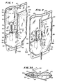
- Fig. 1 is a perspective view of the closed system.
- Fig. 2 is a perspective view of the compressible chamber seen in Fig. 1.
- Fig. 3A is a fragmentary view taken along the
line 3A-3A of Fig. 2. - Fig. 3B is an enlarged fragmentary view in partial cross-section of the retaining tube and frangible cannula.
- Fig. 4 is a partially schematic side elevational view of the closed system during manufacture rotated ninety degrees for ease of illustration on the page.
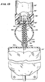
- Fig. 5 is a front elevational view in partial cross-section of the system illustrated in Fig. 1, during manufacture.
- Fig. 6 is a fragmentary, cross-sectional view of the sterile coupling used in the closed system illustrated in Fig. 1.
- Fig. 7 is a fragmentary view of the closed system in partial cross-section, illustrating the establishment of a sterile pathway.
- Fig. 8 is the view illustrated in Fig. 7 and further illustrating the open frangible cannula.
- Fig. 9 is a partially cut-away, front elevational view illustrating liquid transfer .
- Fig. 10 is a partially cut-away, front elevational view illustrating liquid exchange.
- Figs. 11, 12A and 12B are front elevational views of the container illustrating the step of emptying the liquid from the container into the chamber.
- Fig. 13 illustrates an alternate embodiment of the sterile coupling.
- Fig. 14 is a front elevational view of another alternate embodiment of the sterile coupling.
- Figs. 15 and 16 are fragmentary views in partial cross-section of the sterile coupling of Fig. 14, before and after establishment of a sterile pathway, respectively.
- Referring to Figs. 1 through 3, there is seen in Fig. 1 a
closed system 20. Acompressible chamber 22 is provided which may be made fromflexible plastic sheets external seal 28 about thecompressible chamber 22. Theplastic sheets external seal 28 may be, for example, a heat seal or a radio-frequency (RF) seal. Thecompressible chamber 22 includes areservoir compartment 30 and a selectively gas-trappingcompartment 32. The reservoir and gas-trappingcompartments internal wall 34 having aclosed end 36 and anopen end 38. Theinternal wall 34 may also be formed by heat sealing or RF sealing the two flexible plastic sheets together. Theinternal wall 34 may be an extension of theexternal seal 28. Theopen end 38 of theinternal wall 34 may be a wider,rounded seal 40 for increased strength. - The
internal wall 34 segregates the gas-trapping andreservoir compartments internal wall 34 and at theclosed end 36. Theinternal wall 34 defines anopen flow path 42 around theopen end 38, between the gas-trapping andreservoir compartments - The
external seal 28 andinternal wall 34 together define a generally "J"-shaped configuration for the .compressible chamber 22 in the preferred embodiment. Thereservoir compartment 30 corresponds to the long leg of the J-shaped configuration and the gas-trappingcompartment 32 corresponds to the short leg of the J-shaped configuration. Theinternal wall 34 separates the long and short legs. - Means 44 to access the
compressible chamber 22 is located adjacent the gas-trappingcompartment 32. In the preferred embodiment the access means includes aneedle 46 which may be of standard construction, mounted in aplastic needle hub 48. The chamber access means 44 further includes a plastic,flexible sleeve 50 such as may be made with polyvinyl chloride material. Thesleeve 50 may be bonded at itsfirst end 56 to theneedle hub 48, by conventional means such as solvent bonding . The chamber access means 44 further includes amembrane 52 bonded to and closing thesleeve 50 at thesecond end 58 of the sleeve. Themembrane 52 includesannular ribs 54. Themembrane 52 may also be a plastic material. - The
first end 56 of thesleeve 50 is secured into thehollow end 60 of afrangible cannula 62. Such frangible cannulas are known and may be constructed as shown for example, in U.S. Patent Nos. 4,181,140 and 4,294,247 and allowed U.S. patent application Serial No. 086,102 filed October 18, 1979, all assigned to the assignee of the present invention. Referring to Figs. 3A and 3B, it is seen that thefrangible cannula 62 may be housed in a hollow retainingmember 64 which includes one ormore openings 66 in thesidewall 68 of the retainingmember 64, theopenings 66 being located near the top of the short leg of the J-shapedcompressible chamber 22. Thefrangible cannula 62 includes abreakaway portion 72 which may havefins 73 and which may be selectively broken away from thehollow end 60 at thefrangible portion 70. - As seen best in Figs. 1 and 3B, the
external seal 28 is made around thesidewall 68 of the retainingmember 64. If RF sealing is utilized, thesidewall 68 of the retainingmember 64 will simultaneously seal to theplastic sheets hollow end 60 of thefrangible cannula 62 upon application of the RF source. - The
compressible chamber 22 contains afirst component 74 which may be a sterile liquid diluent such as water, dextrose solution or saline solution. Other diluents are of course possible. - The
closed system 20 preferably includes hanging means such as a definedopening 98 through theflexible plastic sheets compressible chamber 22 preferably includes a selectively openedport 100 which may be connected to an administration set (not shown) for delivery to the venous system of a patient. - Referring to Figs. 1 and 6, a
junction 76 encloses theend portion 78 of the chamber access means 44. In the preferred embodiment thejunction 76 is made from an injection moldable plastic material. Thejunction 76 connects the chamber access means 44 with acontainer 80. Thecontainer 80 contains asecond component 82 such as a powdered or liquid drug. In the preferred embodiment, thecontainer 80 is a glass drug vial of standard construction, which allows for the incorporation of drugs into theclosed system 20 from other sources in such standard vials without necessitating retooling for a new drug container. When thecontainer 80 is a drug vial of such standard construction, it typically includes arubber stopper 84 and ametal band 86 about themouth 88 of thecontainer 80, themetal band 86 retaining therubber stopper 84 in thecontainer 80. Therubber stopper 84 andmetal band 86 together form means 90 to access thecontainer 80. As will be described below, neither the chamber access means 44 nor the container access means 90 are limited to the specific construction described herein, but rather can include a wide range of configurations. - The
container 80 may be loosely retained by aflap 92 extending from theflexible plastic sheet 24 and heat sealed at itsdistal end 94 to the other flexibleplastic sheet 26. Aplastic pouch 96 is placed about thecontainer 80. Theplastic pouch 96 may be of a polyolefin material against which thecontainer 80 may easily slide. The polyolefin material has a lower coefficient of friction than, for example, polyvinyl chloride, from which theflexible plastic sheets - The
closed system 20 is manufactured by bringing together thecompressible chamber 22 and thecontainer 30 after the contents of each has been separately sterilized. For example, after theapparatus 102 seen in Fig. 2 is filled with thefirst component 74 it may be placed in a closed pouch (not shown) of a plastic material such as polypropylene. Theapparatus 102 may then be subjected to autoclaving to sterilize the interior of thecompressible chamber 22 and thefirst component 74. Theapparatus 102 is then taken out of the pouch and placed on a preferablyhorizontal surface 103 at a work station with theflexible plastic sheet 24 and theflap 92 face up, as illustrated in Fig. 4. Fig. 4 has been rotated ninety degrees for ease of illustration on the page. The pouching of theapparatus 102 before autoclaving is helpful in promoting a clean environment for the apparatus but is not claved without pouching. After this step, the apparatus can be taken directly to the work station. - The
flap 92 is folded away from the chamber access means 44. Thecontainer 80 is then placed on thehorizontal surface 103. Theend portion 104 of the container access means 90 is biased into abutting relation with theend portion 78 of the chamber access means 44. Theend portions spring mechanism 106. - As seen in Fig. 5, a mold 110 is then placed about the
end portions Molten material 112 is then injected through thesupply line 114 into themold interior 120, about theend portions molten material 112 will be a plastic, and preferably a thermoplastic; however, it is conceivable that other molten materials meeting the requirements described below will also work. In the preferred embodiment, the molten material is a plastic sold under the trademark Kraton by Shell Oil Company. It is believed that Kraton is a block copolymer of polystyrene and a rubbery polyolefin material. Another plastic which may be acceptable is Delrin , sold by E. I. DuPont de Nemours & Co. The plastic should be puncturable but resistant to coring during puncture. The pressure of the injectedmolten material 112 overcomes the bias between theend portions - In order to be in a molten state, the molten material such as molten plastic will be quite hot. It has been found that during injection molding the molten material sterilizes the
end portions molten material 112. When Kraton is used, a temperature of 500°F. or more should be maintained so as to sterilize theend portions molten material 112 will improve the sterilizing - ability of the heat transfer during injection molding. - It has been found that spraying water on the
end portions heated nolten material 112 may improve the sterilizing ability of the heat transfer, although this is not believed necessary in the preferred embodiment. - The
molten material 112 is then cooled into aunitary junction 76 which encloses theend portions needle 46 may be urged through thejunction 76 to selectively establish asterile pathway 118 between thecompressible chamber 22 andcontainer 80 through both access means 44, 90, as seen, for example, in Figs. 7 and 8. - It is believed that the above-described method for establishing and maintaining the sterile spaced relation between the access means may be accomplished without biasing the
end portions end portions end portions - It is believed that since, in the preferred embodiment, the injection molding of molten material occurs only about the container access means 90 of the
container 80, only a minimum amount of heat transfer occurs between themolten material 112 and thesecond component 82 such .as a powdered drug in thecontainer 80, thus maintaining the efficacy of the drug. When a glass vial is used as thecontainer 80, the glass serves as a good insulator against heat transfer between themolten material 112 and thesecond component 82 inside the vial. Therubber stopper 84 also is a good insulator. - It may be seen that the above-described method for establishing and maintaining a sterile spaced relation between the access means 44, 90 is not limited to access means of the specifically described
chamber 22 andcontainer 80. Indeed, any two receptacles may be used in place of thechamber 22 and thecontainer 80. - As stated, the
container 80 in the preferred embodiment is a glass vial having arubber stopper 84 in themouth 88 of the vial. Because of the use of a glass construction and arubber stopper 84, thecontainer 80 can not be subjected to strong stresses. For this reason, the injection molding step described above to form thejunction 76 must be made from a low pressure supply into themold interior 120. Themolten material 112 is injected at a pressure of less than 10 PSI and preferably at a pressure of about 5 PSI. This low pressure injection molding makes impossible an otherwise useful, known technique for determining when themold interior 120 is full. For example, completion of an injection cycle is often determined by monitoring the back pressure in the supply line. When the back pressure of the molten material rises to a certain level it is known that the mold interior is full and injection of further plastic is then stopped. Under the low injection molding pressure requirements, however, it is difficult to determine a significant rise in back pressure of themolten material 112. If the back pressure is allowed to rise, the pressure might either blow therubber stopper 84 into thecontainer 80 or break thecontainer 80. - Other means of determining injection cycle completion include measuring the quantity of molten material injected into the mold interior through the supply line. Such measurement means can be expensive and it is often difficult to perform precise measuring.
- Solving the problem of determining completion of an injection cycle is solved by providing an
open channel 122 in the mold 110, as seen in Fig. 5. Preferably, theopen channel 122 is a formed groove in the side of one of two mold halves which comprise the mold 110. Theopen channel 122 extends between themold interior 120 and the exterior of the mold 110. Theopen channel 122 is preferably placed away from thesupply line 114, although it is believed that this is not necessary. The open channel is relatively narrow compared with themold interior 120 and in the preferred embodiment is within the range of about 0.030 in. to about 0.060 in. wide, when the molten material is Kraton. Aftermolten material 112 has filled themold interior 120, it enters theopen channel 122. The presence of themolten material 112 in theopen channel 122 is then sensed, whereupon the low pressure supply of the molten material ceases. - It is believed that by placing the mold-interior end of the
open channel 122 away from thesupply line 114 and most importantly by making theopen channel 122 narrow, theopen channel 122 becomes the path of greatest resistance to themolten material 112 and is therefore filled with molten material l12 only after themold interior 120 is filled. The object is to make theopen channel 122 the path of greatest resistance but to prevent clogging of the channel and allow molten material to enter thechannel 122. Thus, when the molten material is more viscous, thechannel 122 will need to be wider so as to permitmaterial 112 to enter the open channel and to prevent clogging of thechannel 122, yet still narrow enough to be the path of greatest resistance to themolten material 112. - If the injection molding process is performed manually, the presence of the molten material in the
channel 122 may be sensed visually, whereupon the operator ceases the application of pressure to the material supply. In an automated procedure, the sensing of the molten material in thechannel 122 could be made by various means including, for example, a microswitch (not shown) connected to the inside of theopen channel 122 or at theexterior end 123 of theopen channel 122. The microswitch can be connected to and control the low pressure supply. - When the
molten material 112 cools and becomes thejunction 76, asterile coupling 124 is formed which enables the selective establishment of thesterile pathway 118 between two separate receptacles, such as thecontainer 80 and thecompressible chamber 22. In theclosed system 20 thesterile coupling 124 includes the chamber access means 44, the container access means 90 and the moldedjunction 76 affixed about at least theend portions sterile coupling 124 further includes the piercing element such as theneedle 46 which is capable of piercing thejunction 76 between theend portion sterile pathway 118 between thecontainer 80 and thecompressible chamber 22 through the access means 44, 90. In the preferred embodiment, the needle is housed within and is a part of the chamber access means 44. Theneedle 46 forms the conduit between thecontainer 80 and thechamber 22 when thesterile pathway 118 is formed. However, it is not necessary for the piercing element to be aneedle 46 and it is not necessary for the piercing element to also be the conduit. Other piercing element and conduit configurations may be used in thesterile coupling 124. Indeed, thesterile coupling 124 is not limited to use in the above-describedclosed system 20. For example, thesterile coupling 124 can include first means to access one receptacle and second means to access another receptacle, whereby thejunction 76 is permanently affixed about at least the end portions of both the first and second access means. The piercing element should be capable of piercing the preferably plastic junction from the end portion of the corresponding access means through the junction at least to the end portion of the other of the first and second access means in a manner to establish a sterile pathway through both access means, between the receptacles. - Upon formation of the
sterile coupling 124 in theclosed system 20, the loose fitting, open endedplastic pouch 96 is placed about thecontainer 80, as seen for example in Fig. 1. Theflap 92 is then brought down over thecontainer 80 and heat sealed at itsdistal end 94 to theflexible plastic sheet 26. Theplastic sheet 26,flap 92 andpouch 96 confine thecontainer 80 but allow for axial movement of the container. As stated above, theplastic sheet 26 andflap 94 may be made of polyvinyl chloride material. Such material has a very high coefficient of friction thereby hindering axial movement of thecontainer 80 relative to thecompressible chamber 22. Theplastic pouch 96 is provided merely to reduce the coefficient of friction and ease axial movement of the container. Theplastic pouch 96 may be a polyolefin such as polypropylene, for example. - The
closed system 20 provides for the separate storage of two components and the selective mixing of those components under sterile conditions. Thefirst component 74 in thecompressible chamber 22 and thesecond chamber 82 in thecontainer 80 are mixed by first forming thesterile pathway 118 within thejunction 76 of thesterile coupling 124, as illustrated in Figs. 7 and 8. In the preferred embodiment thesterile pathway 118 is made by urging the piercing element, in this case theneedle 46, through themembrane 52 and theend porticn 78 of the chamber access means 44. After piercing themembrane 52, theneedle 46 pierces thejunction 76 and then therubber stopper 84 of thecontainer 80, therubber stopper 84 being part of the container access means 90. The interior of theneedle 46 is then in communication with the interior of thecontainer 80 housing thesecond component 82. The piercing element is urged toward thecontainer 80 by simply grasping thecontainer 80 and the chamber access means 44 and pushing them toward each other. Theclosed system 20 allows for axial movement of thecontainer 80. - When the
container 80 andneedle 46 are urged together as seen in Fig. 7, thesleeve 50 collapses because of its flexible construction. Thesleeve 50 andmembrane 52 serve to hold the chamber access means 44 within the junction. Theannular ribs 54 about themembrane 52 aid in retaining themembrane 52 within thejunction 76. If thejunction 76 were molded directly about theneedle 46 it might be possible to withdraw theneedle 46 from thejunction 76. While it is believed that such a configuration of the invention will work, the chamber access means 44 including thesleeve 50 andmembrane 52, is preferred. - The
frangible cannula 62 segregates the liquidfirst component 74 from the chamber access means 44, preventing the collection of liquid within thesleeve 50 before thefrangible cannula 62 is opened. In addition, thefrangible cannula 62 provides further assurance that there will be no contamination of thefirst component 74 stored in thecompressible chamber 22. To completely open thesterile pathway 118 between the interiors of thechamber 22 andcontainer 80, thefrangible cannula 62 must be opened. This is done by manipulating thecannula 62 from exterior of thecompressible chamber 22. The break-awayportion 72 is bent relative to thehollow end 60, fracturing thecannula 62 atfrangible portion 70. If desired, the break-awayportion 72 may thereafter be urged away from thehollow end 60 down the retainingmember 64. Thefrangible cannula 62 may be designed so as to includefins 73 on the break-awayportion 72 which frictionally engage the retainingmember 64. The break-awayportion 72 is thus trapped in the retainingmember 64 and does not float loosely within thechamber 22. - After the
sterile pathway 118 is formed and after thefrangible cannula 62 is opened, fluid flow between thecontainer 80 andchamber 22 is made through theneedle 46 and around thefins 73 of thefrangible cannula 62 as well as through the definedopening 66 in the retainingmember 64. Once thesterile pathway 118 is established, the gas-trapping andreservoir compartments second components - The mixing procedure is best seen with reference to Figs. 9 through 12. The method includes the steps of transferring some of the liquid
first component 74 into thecontainer 80 after at least someair 128 is in thecontainer 80, exchanging some of the liquid in the container with some of the liquid in thechamber 22 and finally, emptying the liquid in thecontainer 80 into thechamber 22. - In the illustrated embodiment the liquid,
first component 74 is stored in thecompressible chamber 22 along with at least a small amount ofair 128 or other gas. Thefirst component 74 may be packaged without anyair 128 in the compressible chamber if there is someair 128 stored in thecontainer 80. Powdered drugs are often stored in drug vials under partial vacuums, however, and thus additional air is required for the working of the invention. Thus,air 128 is stored in thechamber 22. - Liquid transfer from the
chamber 22 into thecontainer 80 is accomplished by manipulating thechamber 22 until the liquidfirst mixing component 74 is adjacent the chamber access means 44, as seen in Fig. 9. Thechamber 22, being made of flexibleplastic sheets chamber 22 into contact with thesecond mixing component 82 in thecontainer 80. The liquid is transferred most easily if theclosed system 20 is maintained horizontally with the gas-trappingcompartment 32 and thecontainer 80 beneath thereservoir compartment 30, such as is shown in Fig. 9. It is important to stop compression of thechamber 22 before thecontainer 80 is totally filled with liquid. If the container 80-is packaged with a vacuum, it would otherwise be possible to fill the container totally with liquid. - After some of the
first component 74 is in thecontainer 80, thecontainer 80 is agitated by shaking theclosed system 20. This mixes thefirst component 74 with thesecond component 82. In those instances where thesecond component 82 is a powder, agitation of the container is most useful in initiating a mixing between the components. This is especially true where the powder has "caked" into a single piece, which provides for only small surface area contact between the components. Agitation helps to break up thesecond component 82 into smaller particles. - After the step of liquid transfer, some of the liquid in the
container 80 is exchanged with some of the liquid in thechamber 22, as best seen in Fig. 10. First, the chamber is manipulated until liquid, as opposed toair 128, is in the gas-trappingcompartment 32 of thechamber 22 adjacent the chamber access means 44 and until the chamber access means 44 is above the gas-trappingcompartment 32. The J-shaped configuration of thecompressible chamber 22 allows for liquid in thechamber 22 to be adjacent the chamber access means 44 while still holding theclosed system 20 in the upright position shown in Fig. 10. Anyair 128 in thechamber 22 can be stored entirely in thereservoir compartment 30. This is accomplished by manipulating the position of theclosed system 20 so thatair 128 in the gas-trappingcompartment 32 flows through theopen flow path 42. - The chamber may then be manually compressed, which urges some of the liquid in the gas-trapping
compartment 32 of thechamber 22 into thecontainer 80. During the compression step, air in thecontainer 80 which is above the liquid in thecontainer 80 is pressurized. Compression of the chamber is then stopped. When compression ceases the pressurized air in the container forces some of the liquid from the container into thechamber 22. The liquidfirst component 74 now has some of thesecond component 82 mixed therewith. - Were it not for the unique shape of the
compressible chamber 22, the liquid exchange step would be performed by first turning thesystem 20 upside down so that the chamber access means 44 would be below the gas-trapping compartment and then pressing the chamber. Then, while still exerting pressure on the chamber to compress it, the closed system would have to be rotated approximately 180° until the air in thecontainer 80 is positioned above the liquid in the container. Only then could compression of thechamber 22 be stopped, which would then urge liquid from thecontainer 80 into thechamber 22. - The liquid exchange step of the mixing method transfers some of the
second component 82 into thechamber 22 and places additional amounts of the liquidfirst component 74, having a lower concentration of thesecond component 82 therein, into contact with any amount of second component remaining in thecontainer 80. By placing the less highly concentrated mixture into contact with the remaining portion of thesecond component 82, thorough mixture of the twocomponents closed system 20 may be agitated to facilitate mixing. Repetition of the liquid exchange step is most useful when the second component is, for example, a powdered drug. - After a homogenous mixture between the first and second components has been created, or after all powder has been disolved, the liquid in the container is emptied into the chamber, leaving virtually none of either the first or
second components container 80. The liquid emptying step is best illustrated in Figs. 11, 12A and 12B. First, thechamber 22 is manipulated until at least some of theair 128 in thereservoir compartment 30 enters the gas-trappingcompartment 32 through theopen flow path 42 between the gas-trapping andreservoir compartments closed system 20 approximately 90° from the position of Fig. 10, shown by phamtom line in Fig. 11, to the substantially horizontal position illustrated by solid line in Fig. 11. In order to insure thanair 128 flows around theinternal wall 34, through theopen flow path 42 and into the gas-trappingcompartment 32, it is desirable to rotate theclosed system 20 until theport tube end 130 is somewhat higher than the hangingend 132. This is depicted schematically by the lines 134 in Fig. 11. - Next, the chamber is manipulated until the
air 128 in the gas-trappingcompartment 32 is adjacent the chamber access means 44. This arrangement is shown in Fig. 12A, in which theclosed system 20 has been rotated approximately 90° counterclockwise. Theinternal wall 34, in addition to defining and partially segregating the gas-trapping andreservoir compartments air 128 in the gas-trappingcompartment 32 adjacent the chamber access means 44. The next step in emptying the liquid from the container is to compress the chamber as seen in Fig. 12A. This compression urges at least some of the air in the gas-trappingcompartment 32 into thecontainer 80, thereby pressurizing theair 128 above the liquid in thecontainer 80. Compression of the chamber is then stopped and, as illustrated in Fig. 12B the now pressurized air in thecontainer 80 expels the liquid in the container through thesterile pathway 118 into thechamber 22. - Mixing is now complete. A homogenous mixture is in the
compressible chamber 22. Thecontainer 80 is virtually empty. Theclosed system 20 may now be used as a supply container to deliver the mixture in thechamber 22 directly to a patient. A spike of an administration set may be inserted into theport 100 to accomplish this fluid delivery. - The uniquely designed
compressible chamber 22 of the invention may also be utilized without thesterile coupling 124 previously described. The compressible chamber having a selectively gas-trapping compartment and a reservoir compartment with an open flow path therebetween, may, in combination with, or for future attachment to a container, comprise an apparatus for separately storing and selectively mixing components or for mixing a liquid first component stored therein with a second component stored in the future connected container. When the apparatus includes the compressible chamber and the container, theclosed system 20 is such an apparatus, but the container and chamber may be connected by any selectively opened pathway between the chamber and container and is not limited to use of thejunction 76. For example, thecontainer 80 andchamber 22 may have a selectively opened pathway which is a conduit having a frangible cannula therein. The selectively opened pathway may have a configuration different from those described above. At least one of the container and the compressible chamber also contains a gas. The apparatus is useful for mixing two components even when sterile conditions are not necessitated. - When the apparatus does not include the container, the
apparatus 102 may be as shown in Fig. 2, for example. Theapparatus 102 includes means to access the gas-trapping compartment so that this access means 44 can be selectively connected to a separate container to form a selectively opened pathway between the container and chamber. - Figs. 14 through 16 illustrate an alternate embodiment of the sterile coupling described above. In this embodiment, there is provided a
closed device 136 including a compressibleprimary chamber 138 and a compressibleauxiliary chamber 140. Thechambers Area 141 has no function other than to provide a uniform appearance to thedevice 136. A port 100' provides for selective communication between theprimary chamber 138 and the exterior of thedevice 136. -
Tubes auxiliary chambers tubes cap portion 150 which may be made of a needle pierceable plastic or rubber material. The first end 56' of a flexible sleeve 50' is attached to thecap portion 150. The second end 58' of the sleeve 50' is attached to and closed by a pierceable membrane 52'. Housed within the sleeve 50' are two doublepointed needles tubes cap portion 150, sleeve 50', membrane 52' and doublepointed needles auxiliary chambers cap portion 150, theneedles tubes - A liquid first component 74' is stored in the
primary chamber 138. A second component 82' is stored in the container 80'. Theauxiliary chamber 140 remains empty until mixing is desired, at which time the container 80' is urged toward the first access means. Both of the double pointedneedles cap portion 150. An open fluid passage is then established as seen in Fig. 16. The fluid passage extends from theprimary chamber 138 through thetube 142, and the double pointedneedle 152 into the container 80'. The fluid passage continues from the container 80', through the double pointedneedle 154 and thetube 144, into theauxiliary chamber 140. - Mixing is accomplished by first compressing the
primary chamber 138 to urge liquid therein into the container 80'and from the container into theauxiliary chamber 140. Next, theauxiliary chamber 140 is compressed, reversing the fluid flow, through the container 80' to theprimary chamber 138. This cycle is repeated until the first and second components 74', 82' are mixed. The port 100' may then be opened and the mixture delivered. The use of the primary andauxiliary chambers - The above-described
closed device 136 provides a sterile pathway utilizing the sterile coupling, without the J-shaped configuration chamber. - Yet another embodiment of the sterile coupling is seen in Fig. 13. Here, the junction 76'' is affixed about a rubber stopper 84'' serving as an access means to a container 80'' or other receptacle. The junction 76'' connects the container 80'' to another receptacle, a first
component storage unit 156. The access means to thestorage unit 156 includes aflexible balloon 158 attached at one end to aninlet port 160 of the storage unit and at the other end to the junction 76''. The storage unit access means further includes aneedle housing 162 having a doublepointed needle 164 and two singlepointed needles needle housing 162 further includescheck valves balloon interior 159 and the single pointedneedles - Communication between the
storage unit 156 and container 80'' is established by bringing the two receptacles toward each other, thereby compressing theballoon 158 as illustrated, forcing theneedle housing 162 toward both the junction 76'' and theinlet port 160. Theneedles needles inlet port 160. Fluid may then be transferred from thestorage unit 156 through the singlepointed needle 168 and into theballoon interior 159 through thecheck valve 172. The fluid may continue from theballoon interior 159 through thecheck valve 170 and theneedle 166 into thecontainer 80". Fluid is free to flow from the container 80'' into thestorage unit 156 through the double pointedneedle 164. Theballoon 158 and thecheck valves balloon 158. Theballoon 158 may be repeatedly squeezed to effect a pumping action, thereby mixing the first and second components 74'' and 82 ''.
Claims (13)
Applications Claiming Priority (3)
| Application Number | Priority Date | Filing Date | Title |
|---|---|---|---|
| US06/365,945 US4458733A (en) | 1982-04-06 | 1982-04-06 | Mixing apparatus |
| US365943 | 1982-04-06 | ||
| US06/365,943 US4411662A (en) | 1982-04-06 | 1982-04-06 | Sterile coupling |
Publications (3)
| Publication Number | Publication Date |
|---|---|
| EP0091311A2 true EP0091311A2 (en) | 1983-10-12 |
| EP0091311A3 EP0091311A3 (en) | 1984-12-12 |
| EP0091311B1 EP0091311B1 (en) | 1988-01-27 |
Family
ID=39744045
Family Applications (2)
| Application Number | Title | Priority Date | Filing Date |
|---|---|---|---|
| EP19830301906 Expired EP0091311B1 (en) | 1982-04-06 | 1983-04-05 | Sterile coupling and method of making same |
| EP83301907A Withdrawn EP0091312A3 (en) | 1982-04-06 | 1983-04-05 | Apparatus and method for mixing separately stored components |
Family Applications After (1)
| Application Number | Title | Priority Date | Filing Date |
|---|---|---|---|
| EP83301907A Withdrawn EP0091312A3 (en) | 1982-04-06 | 1983-04-05 | Apparatus and method for mixing separately stored components |
Country Status (14)
| Country | Link |
|---|---|
| US (3) | US4458733A (en) |
| EP (2) | EP0091311B1 (en) |
| JP (1) | JPS59500602A (en) |
| AU (2) | AU1478083A (en) |
| BR (1) | BR8306786A (en) |
| CA (2) | CA1208624A (en) |
| DE (1) | DE3375453D1 (en) |
| DK (1) | DK556583A (en) |
| ES (2) | ES8406876A1 (en) |
| GR (2) | GR77862B (en) |
| IL (2) | IL68160A0 (en) |
| NO (1) | NO834431L (en) |
| WO (2) | WO1983003585A1 (en) |
| ZA (2) | ZA832334B (en) |
Cited By (4)
| Publication number | Priority date | Publication date | Assignee | Title |
|---|---|---|---|---|
| DE3510166A1 (en) * | 1985-03-21 | 1987-01-22 | Tecnotrans Ag | REFILL CAP FOR CHEMICAL-PHARMACEUTICAL SUBSTANCES AND METHOD FOR THE PRODUCTION THEREOF |
| US5463361A (en) * | 1991-11-18 | 1995-10-31 | Motorola, Inc. | Surface acoustic wave filter and method |
| WO2010023564A3 (en) * | 2008-08-02 | 2010-10-28 | Walter Pobitschka | Device and method for transferring a substance from a closed source system into a target system |
| EP3659704A1 (en) * | 2014-06-16 | 2020-06-03 | Life Technologies Corporation | Reagent mixer and fluid control devices |
Families Citing this family (242)
| Publication number | Priority date | Publication date | Assignee | Title |
|---|---|---|---|---|
| US4484920A (en) * | 1982-04-06 | 1984-11-27 | Baxter Travenol Laboratories, Inc. | Container for mixing a liquid and a solid |
| US4614267A (en) * | 1983-02-28 | 1986-09-30 | Abbott Laboratories | Dual compartmented container |
| SE434700B (en) * | 1983-05-20 | 1984-08-13 | Bengt Gustavsson | DEVICE FOR AIRED TRANSFER OF SUBSTANCE FROM A KERLE TO ANOTHER |
| US4548606A (en) * | 1983-09-29 | 1985-10-22 | Abbott Laboratories | Dual compartmented container with activating means |
| US4507114A (en) * | 1983-10-21 | 1985-03-26 | Baxter Travenol Laboratories, Inc. | Multiple chamber container having leak detection compartment |
| US4573967A (en) * | 1983-12-06 | 1986-03-04 | Eli Lilly And Company | Vacuum vial infusion system |
| US4591049A (en) * | 1984-01-16 | 1986-05-27 | Kidde, Inc. | Hermetically sealed two-component mixing system |
| US4583971A (en) * | 1984-02-10 | 1986-04-22 | Travenol European Research And Development Centre (Teradec) | Closed drug delivery system |
| DK154884A (en) * | 1984-03-13 | 1985-09-14 | Medesign A S | AID FOR PREPARING INJECTIVE MEDICINES |
| US4581014A (en) * | 1984-04-03 | 1986-04-08 | Ivac Corporation | Fluid infusion system |
| IT1214872B (en) * | 1984-04-06 | 1990-01-18 | Mariano Feriani | BAG CONTAINING TWO OR MORE SUBSTANCES FOR INFUSION FOR MEDICAL USE, PLACED IN SEPARATE COMPARTMENTS, INCLUDING MEANS SUITABLE TO ALLOW THE MIXING OF SUCH SUBSTANCES ONLY AT THE TIME OF USE. |
| US4607671A (en) * | 1984-08-21 | 1986-08-26 | Baxter Travenol Laboratories, Inc. | Reconstitution device |
| US4759756A (en) * | 1984-09-14 | 1988-07-26 | Baxter Travenol Laboratories, Inc. | Reconstitution device |
| JPS6194664A (en) * | 1984-10-15 | 1986-05-13 | テルモ株式会社 | Puncture cock body |
| JPS62501270A (en) * | 1984-12-03 | 1987-05-21 | バクスタ−、インターナショナル、インコ−ポレイテッド | Drug release device to prevent local and systemic toxicity |
| EP0247704A3 (en) | 1984-12-03 | 1988-01-27 | BAXTER INTERNATIONAL INC. (a Delaware corporation) | Receptacle for intravenous delivery system |
| US4874366A (en) * | 1984-12-03 | 1989-10-17 | Baxter Internatiional Inc. | Housing enabling passive mixing of a beneficial agent with a diluent |
| DE3522645A1 (en) * | 1985-06-25 | 1987-01-08 | Hausmann Ag Labor | METHOD AND DEVICE FOR STERILY MIXING PARENTERAL LIQUIDS TO BE DELIVERED |
| US4675020A (en) * | 1985-10-09 | 1987-06-23 | Kendall Mcgaw Laboratories, Inc. | Connector |
| US4735608A (en) * | 1986-05-14 | 1988-04-05 | Del F. Kahan | Apparatus for storing and reconstituting antibiotics with intravenous fluids |
| US4961448A (en) * | 1986-06-13 | 1990-10-09 | R. E. Timm & Associates, Inc. | Pressure vessel for dispensing materials and method for filling same |
| US4832690A (en) * | 1987-01-23 | 1989-05-23 | Baxter International Inc. | Needle-pierceable cartridge for drug delivery |
| US4784259A (en) * | 1987-01-30 | 1988-11-15 | Abbott Laboratories | Container construction with vaned extractor |
| US4784658A (en) * | 1987-01-30 | 1988-11-15 | Abbott Laboratories | Container construction with helical threaded extractor |
| US4842028A (en) * | 1987-05-13 | 1989-06-27 | Baxter International Inc. | Fluid transfer apparatus |
| US4909287A (en) * | 1987-05-20 | 1990-03-20 | Surgikos, Inc. | Fluid injection system |
| CH686778A5 (en) * | 1987-05-29 | 1996-06-28 | Vifor Medical Ag | Container for separate storage of active compounds and their subsequent mixing. |
| US4902287A (en) * | 1987-09-24 | 1990-02-20 | Miles Inc. | Sterilizable system for blood storage |
| US4804366A (en) * | 1987-10-29 | 1989-02-14 | Baxter International Inc. | Cartridge and adapter for introducing a beneficial agent into an intravenous delivery system |
| US5964785A (en) * | 1988-01-25 | 1999-10-12 | Baxter International Inc. | Bayonet look cannula for pre-slit y-site |
| US5100394A (en) * | 1988-01-25 | 1992-03-31 | Baxter International Inc. | Pre-slit injection site |
| EP0544653B1 (en) | 1988-01-25 | 1996-06-05 | Baxter International Inc. | Injection site |
| US5195992A (en) * | 1988-05-13 | 1993-03-23 | Baxter International Inc. | Protector shield for needles |
| US5176673A (en) * | 1988-06-02 | 1993-01-05 | Piero Marrucchi | Method and device for manipulating and transferring products between confined volumes |
| ATE179632T1 (en) * | 1988-06-02 | 1999-05-15 | Piero Marrucchi | DEVICE FOR TREATING AND TRANSFERING SUBSTANCES BETWEEN ENCLOSED ROOMS |
| CA1330412C (en) | 1988-07-08 | 1994-06-28 | Steven C. Jepson | Pre-slit injection site and tapered cannula |
| IE72466B1 (en) | 1989-03-17 | 1997-04-09 | Baxter Int | Blunt-ended cannula device |
| US4974457A (en) * | 1989-04-13 | 1990-12-04 | Hightech Network S.C.I. Ab | Apparatus and method for providing a passage in a sealing member of a container of a fluid sample |
| US4997430A (en) * | 1989-09-06 | 1991-03-05 | Npbi Nederlands Produktielaboratorium Voor Bloedtransfusieapparatuur En Infusievloeistoffen B.V. | Method of and apparatus for administering medicament to a patient |
| US5290558A (en) * | 1989-09-21 | 1994-03-01 | Osteotech, Inc. | Flowable demineralized bone powder composition and its use in bone repair |
| US5073373A (en) * | 1989-09-21 | 1991-12-17 | Osteotech, Inc. | Flowable demineralized bone powder composition and its use in bone repair |
| US5341854A (en) * | 1989-09-28 | 1994-08-30 | Alberta Research Council | Robotic drug dispensing system |
| US5052554A (en) * | 1989-12-13 | 1991-10-01 | Leonard Peter H | Dental impression material package and method |
| US5304163A (en) * | 1990-01-29 | 1994-04-19 | Baxter International Inc. | Integral reconstitution device |
| EP0442406B1 (en) * | 1990-02-14 | 1995-07-26 | Material Engineering Technology Laboratory, Inc. | Filled and sealed, self-contained mixing container |
| US5492534A (en) * | 1990-04-02 | 1996-02-20 | Pharmetrix Corporation | Controlled release portable pump |
| US5318540A (en) * | 1990-04-02 | 1994-06-07 | Pharmetrix Corporation | Controlled release infusion device |
| US5284772A (en) * | 1990-04-13 | 1994-02-08 | T Systems Inc. | Specimen collection and analysis bag |
| US5122116A (en) * | 1990-04-24 | 1992-06-16 | Science Incorporated | Closed drug delivery system |
| US5267957A (en) * | 1990-04-24 | 1993-12-07 | Science Incorporated | Closed drug delivery system |
| US5102408A (en) * | 1990-04-26 | 1992-04-07 | Hamacher Edward N | Fluid mixing reservoir for use in medical procedures |
| US5169388A (en) * | 1990-06-07 | 1992-12-08 | Gensia Pharmaceuticals, Inc. | Pressure-activated medication dispenser |
| AU658845B2 (en) * | 1990-08-20 | 1995-05-04 | Abbott Laboratories | Medical drug formulation and delivery system |
| US5490848A (en) * | 1991-01-29 | 1996-02-13 | The United States Of America As Represented By The Administrator Of The National Aeronautics And Space Administration | System for creating on site, remote from a sterile environment, parenteral solutions |
| US5484431A (en) * | 1991-01-29 | 1996-01-16 | The United States Of America As Represented By The Administrator Of The National Aeronautics And Space Administration | System for creating at a site, remote from a sterile environment, a parenteral solution |
| US5116316A (en) * | 1991-02-25 | 1992-05-26 | Baxter International Inc. | Automatic in-line reconstitution system |
| JPH05123377A (en) * | 1991-05-29 | 1993-05-21 | Fujisawa Pharmaceut Co Ltd | Infusion device |
| US5364598A (en) * | 1991-07-30 | 1994-11-15 | T-Systems, Inc. | System for sampling fluid |
| US5776125A (en) * | 1991-07-30 | 1998-07-07 | Baxter International Inc. | Needleless vial access device |
| US5259954A (en) * | 1991-12-16 | 1993-11-09 | Sepratech, Inc. | Portable intravenous solution preparation apparatus and method |
| CA2588574A1 (en) | 1991-12-18 | 1993-06-24 | Icu Medical, Inc. | Medical valve |
| JPH05212090A (en) * | 1992-02-04 | 1993-08-24 | Material Eng Tech Lab Inc | Transfusion container |
| US5494196A (en) * | 1992-03-16 | 1996-02-27 | Healthtek, Inc. | System for filling medical nutrition containers |
| US5385545A (en) * | 1992-06-24 | 1995-01-31 | Science Incorporated | Mixing and delivery system |
| US5484410A (en) * | 1992-06-24 | 1996-01-16 | Science Incorporated | Mixing and delivery system |
| US5351383A (en) * | 1992-07-29 | 1994-10-04 | Minnesota Mining And Manufacturing Company | Method of making an injection or sampling site |
| US5300034A (en) * | 1992-07-29 | 1994-04-05 | Minnesota Mining And Manufacturing Company | Iv injection site for the reception of a blunt cannula |
| US5810398A (en) * | 1992-10-02 | 1998-09-22 | Pall Corporation | Fluid delivery systems and methods and assemblies for making connections |
| US5385547A (en) * | 1992-11-19 | 1995-01-31 | Baxter International Inc. | Adaptor for drug delivery |
| AU667623B2 (en) * | 1993-01-19 | 1996-03-28 | Baxter International Inc. | Multiple chamber container |
| US5334180A (en) * | 1993-04-01 | 1994-08-02 | Abbott Laboratories | Sterile formed, filled and sealed flexible container |
| US5364386A (en) * | 1993-05-05 | 1994-11-15 | Hikari Seiyaku Kabushiki Kaisha | Infusion unit |
| US5817083A (en) * | 1993-05-31 | 1998-10-06 | Migda Inc. | Mixing device and clamps useful therein |
| IL105852A (en) * | 1993-05-31 | 1996-09-12 | Travenol Lab Ltd | Mixing device and clamps useful therein |
| US5431174A (en) * | 1994-04-04 | 1995-07-11 | Via Medical Corporation | Method of fluid delivery and collection |
| US5470319A (en) | 1994-06-20 | 1995-11-28 | Critical Device Corporation | Needleless injection site |
| AU2945495A (en) | 1994-06-24 | 1996-01-19 | Icu Medical, Inc. | Fluid transfer device and method of use |
| US5526853A (en) * | 1994-08-17 | 1996-06-18 | Mcgaw, Inc. | Pressure-activated medication transfer system |
| SE509950C2 (en) | 1995-05-02 | 1999-03-29 | Carmel Pharma Ab | Device for the administration of toxic liquid |
| KR19990021913A (en) * | 1995-05-25 | 1999-03-25 | 피터 빌헬름 스토커 | Distribution and Preparation of Intravenous Solution |
| US5766147A (en) * | 1995-06-07 | 1998-06-16 | Winfield Medical | Vial adaptor for a liquid delivery device |
| US6277095B1 (en) | 1995-10-11 | 2001-08-21 | Science Incorporated | Fluid delivery device with full adapter |
| FR2740198B1 (en) * | 1995-10-18 | 1997-12-05 | Cooperative Bretonne D Insemin | DEVICE FOR CONNECTING A FLEXIBLE CONTAINER TO AN EXTERNAL PIPING, AND ITS APPLICATIONS |
| US5738663A (en) | 1995-12-15 | 1998-04-14 | Icu Medical, Inc. | Medical valve with fluid escape space |
| US5810792A (en) * | 1996-04-03 | 1998-09-22 | Icu Medical, Inc. | Locking blunt cannula |
| US5735320A (en) * | 1996-08-21 | 1998-04-07 | The Sherwin-Williams Company | Dispenser for a two-part composition |
| ZA978002B (en) | 1996-09-11 | 1998-03-02 | Baxter Int | Containers and methods for storing and admixing medical solutions. |
| US5865308A (en) * | 1996-10-29 | 1999-02-02 | Baxter International Inc. | System, method and device for controllably releasing a product |
| EP1716885A3 (en) | 1997-05-09 | 2006-11-15 | Pall Corporation | Connector assemblies, fluid systems, and methods for making a connection |
| US5957898A (en) | 1997-05-20 | 1999-09-28 | Baxter International Inc. | Needleless connector |
| EP0923391B1 (en) | 1997-05-20 | 2006-08-09 | Baxter International Inc. | Needleless connector |
| SE512489C2 (en) * | 1997-07-14 | 2000-03-27 | Arom Pak Ab | Aseptic connection device |
| AU9104498A (en) | 1997-08-22 | 1999-03-16 | Deka Products Limited Partnership | System and method for intelligent admixture and delivery of medications |
| US6070761A (en) | 1997-08-22 | 2000-06-06 | Deka Products Limited Partnership | Vial loading method and apparatus for intelligent admixture and delivery of intravenous drugs |
| US6159192A (en) | 1997-12-04 | 2000-12-12 | Fowles; Thomas A. | Sliding reconstitution device with seal |
| US6162206A (en) * | 1997-12-23 | 2000-12-19 | Baxter International Inc. | Resealable access site |
| EP1100566A4 (en) * | 1998-07-27 | 2002-03-20 | Medi Ject Corp | Loading mechanism for medical injector assembly |
| US7074216B2 (en) | 1998-09-15 | 2006-07-11 | Baxter International Inc. | Sliding reconstitution device for a diluent container |
| US6113583A (en) | 1998-09-15 | 2000-09-05 | Baxter International Inc. | Vial connecting device for a sliding reconstitution device for a diluent container |
| US7358505B2 (en) | 1998-09-15 | 2008-04-15 | Baxter International Inc. | Apparatus for fabricating a reconstitution assembly |
| AR021220A1 (en) | 1998-09-15 | 2002-07-03 | Baxter Int | CONNECTION DEVICE FOR ESTABLISHING A FLUID COMMUNICATION BETWEEN A FIRST CONTAINER AND A SECOND CONTAINER. |
| US7425209B2 (en) | 1998-09-15 | 2008-09-16 | Baxter International Inc. | Sliding reconstitution device for a diluent container |
| US6202708B1 (en) * | 1998-11-09 | 2001-03-20 | Sims Deltec, Inc. | Fillable cassette apparatus and method |
| US6527738B1 (en) * | 1999-04-30 | 2003-03-04 | Prismedical Corporation | Drug delivery pack |
| US7025877B1 (en) | 1999-06-03 | 2006-04-11 | Baxter International Inc. | Processing set for processing and treating a biological fluid |
| US7445756B2 (en) * | 1999-06-03 | 2008-11-04 | Fenwal, Inc. | Fluid processing sets and organizers for the same |
| US6565802B1 (en) | 1999-06-03 | 2003-05-20 | Baxter International Inc. | Apparatus, systems and methods for processing and treating a biological fluid with light |
| US7068361B2 (en) * | 1999-06-03 | 2006-06-27 | Baxter International | Apparatus, systems and methods for processing and treating a biological fluid with light |
| US6364864B1 (en) | 1999-06-03 | 2002-04-02 | Baxter International Inc. | Plastic containers having inner pouches and methods for making such containers |
| US7479131B2 (en) * | 1999-07-29 | 2009-01-20 | Fenwal, Inc. | Biological fluid sampling apparatus, assembly and method |
| US20030228288A1 (en) | 1999-10-15 | 2003-12-11 | Scarborough Nelson L. | Volume maintaining osteoinductive/osteoconductive compositions |
| US6428505B1 (en) | 1999-11-19 | 2002-08-06 | Prismedical Corporation | In-line IV drug delivery pack with controllable dilution |
| US7635390B1 (en) | 2000-01-14 | 2009-12-22 | Marctec, Llc | Joint replacement component having a modular articulating surface |
| US6406175B1 (en) | 2000-05-04 | 2002-06-18 | James F. Marino | Bone cement isovolumic mixing and injection device |
| US6695817B1 (en) | 2000-07-11 | 2004-02-24 | Icu Medical, Inc. | Medical valve with positive flow characteristics |
| US9387094B2 (en) * | 2000-07-19 | 2016-07-12 | Warsaw Orthopedic, Inc. | Osteoimplant and method of making same |
| US6610033B1 (en) | 2000-10-13 | 2003-08-26 | Incept, Llc | Dual component medicinal polymer delivery system and methods of use |
| US7323193B2 (en) * | 2001-12-14 | 2008-01-29 | Osteotech, Inc. | Method of making demineralized bone particles |
| CA2448696A1 (en) * | 2001-05-04 | 2002-11-14 | Prismedical Corporation | Dual chamber dissolution container with passive agitation |
| CN100351006C (en) * | 2001-05-14 | 2007-11-28 | 沃特海尔斯国际公司 | Powered sterile solution device |
| US7163691B2 (en) | 2001-10-12 | 2007-01-16 | Osteotech, Inc. | Bone graft |
| US6908459B2 (en) * | 2001-12-07 | 2005-06-21 | Becton, Dickinson And Company | Needleless luer access connector |
| WO2004009323A2 (en) * | 2002-07-24 | 2004-01-29 | Erik Forsberg | Apparatus and method for manufacturing and assembling sterile containers |
| US20040062694A1 (en) * | 2002-10-01 | 2004-04-01 | Vandlik Mark R. | One-piece connector for assembling a sterile medical product |
| US7086431B2 (en) * | 2002-12-09 | 2006-08-08 | D'antonio Consultants International, Inc. | Injection cartridge filling apparatus |
| AU2004247143B2 (en) | 2003-06-11 | 2010-09-23 | Warsaw Orthopedic, Inc. | Osteoimplants and methods for their manufacture |
| EP1491177A1 (en) * | 2003-06-27 | 2004-12-29 | Nipro Corporation | Displaceable-plug-containing filling/discharging port and medical container having the same |
| US7641851B2 (en) | 2003-12-23 | 2010-01-05 | Baxter International Inc. | Method and apparatus for validation of sterilization process |
| US20050133729A1 (en) * | 2003-12-23 | 2005-06-23 | Archie Woodworth | Apparatus and method for fabricating a reconstitution assembly |
| US7275640B2 (en) * | 2004-02-05 | 2007-10-02 | Boston Scientific Scimed, Inc. | Packaging for imparting anti-microbial properties to a medical device |
| US7441652B2 (en) * | 2004-05-20 | 2008-10-28 | Med Institute, Inc. | Mixing system |
| US7731678B2 (en) | 2004-10-13 | 2010-06-08 | Hyprotek, Inc. | Syringe devices and methods for mixing and administering medication |
| JP2008518719A (en) | 2004-11-05 | 2008-06-05 | アイシーユー メディカル インコーポレイテッド | Medical soft grip connector |
| US20060157507A1 (en) * | 2004-12-30 | 2006-07-20 | Chang Byeong S | Multi-functional container closure delivery system |
| US7959600B2 (en) | 2004-12-30 | 2011-06-14 | Byeong S. Chang | Container closure delivery system |
| US20060144869A1 (en) | 2004-12-30 | 2006-07-06 | Chang Byeong S | Container closure delivery system |
| US7935070B2 (en) * | 2005-01-28 | 2011-05-03 | Fresenius Medical Care North America | Systems and methods for dextrose containing peritoneal dialysis (PD) solutions with neutral pH and reduced glucose degradation product |
| US7670322B2 (en) * | 2005-02-01 | 2010-03-02 | Icu Medical, Inc. | Check valve for medical Y-site |
| US7905868B2 (en) | 2006-08-23 | 2011-03-15 | Medtronic Minimed, Inc. | Infusion medium delivery device and method with drive device for driving plunger in reservoir |
| DE202005009755U1 (en) * | 2005-06-21 | 2005-09-08 | Cervitech, Inc. | Device for temporary accommodation of implant replacing intervertebral disk, comprising stepped holding area |
| US20070074980A1 (en) * | 2005-09-02 | 2007-04-05 | Bankoski Brian R | Implant rehydration packages and methods of use |
| US20070082035A1 (en) * | 2005-10-06 | 2007-04-12 | New York Blood Center, Inc. | Anti-infective hygiene products based on cellulose acetate phthalate |
| JP2009513294A (en) * | 2005-10-30 | 2009-04-02 | メディモップ・メディカル・プロジェクツ・リミテッド | Needleless additive control valve |
| WO2007056671A1 (en) * | 2005-11-02 | 2007-05-18 | Osteotech, Inc. | Hemostatic bone graft |
| JP2009519047A (en) | 2005-11-09 | 2009-05-14 | ハイプロテック、 インク. | Syringe device, syringe device component, and method of forming component and syringe device |
| US7547300B2 (en) | 2006-04-12 | 2009-06-16 | Icu Medical, Inc. | Vial adaptor for regulating pressure |
| WO2008077180A1 (en) * | 2006-06-02 | 2008-07-03 | Michael John William Hirsch | Filling apparatus for wet cell battery |
| US7473246B2 (en) * | 2006-06-22 | 2009-01-06 | Baxter International Inc. | Medicant reconstitution container and system |
| US20080027443A1 (en) * | 2006-07-26 | 2008-01-31 | Lambert Systms, L.L.C. | Biocompatible Anchoring Device For A Soft Tissue Graft, Method Of Making And Method Of Using |
| WO2008014427A2 (en) * | 2006-07-26 | 2008-01-31 | Lambert Systems, L.L.C. | Device for delivering bone cement precursors, composites thereof, supporting members, and methods of using the same |
| US8105314B2 (en) | 2006-10-25 | 2012-01-31 | Icu Medical, Inc. | Medical connector |
| EP1935605A1 (en) * | 2006-12-21 | 2008-06-25 | BTG International Limited | Method and apparatus for producing foam |
| ES2402904T3 (en) * | 2006-12-21 | 2013-05-10 | Btg International Limited | Device and method for producing therapeutic foam |
| US9358135B2 (en) * | 2007-04-17 | 2016-06-07 | Warsaw Orthopedic, Inc. | Devices, methods and systems for hydrating a medical implant material |
| WO2008136845A2 (en) | 2007-04-30 | 2008-11-13 | Medtronic Minimed, Inc. | Reservoir filling, bubble management, and infusion medium delivery systems and methods with same |
| US7963954B2 (en) | 2007-04-30 | 2011-06-21 | Medtronic Minimed, Inc. | Automated filling systems and methods |
| DE102007046951B3 (en) * | 2007-10-01 | 2009-02-26 | B. Braun Melsungen Ag | Device for introducing a medicament into an infusion container |
| US9522097B2 (en) | 2007-10-04 | 2016-12-20 | Hyprotek, Inc. | Mixing/administration syringe devices, protective packaging and methods of protecting syringe handlers |
| US8002737B2 (en) | 2007-10-04 | 2011-08-23 | Hyprotek, Inc. | Mixing/administration syringe devices, protective packaging and methods of protecting syringe handlers |
| US20090270832A1 (en) * | 2008-04-23 | 2009-10-29 | Baxter International Inc. | Needleless port assembly for a container |
| US7905873B2 (en) * | 2008-07-03 | 2011-03-15 | Baxter International Inc. | Port assembly for use with needleless connector |
| US8172823B2 (en) * | 2008-07-03 | 2012-05-08 | Baxter International Inc. | Port assembly for use with needleless connector |
| US8062280B2 (en) * | 2008-08-19 | 2011-11-22 | Baxter Healthcare S.A. | Port assembly for use with needleless connector |
| WO2010022095A1 (en) | 2008-08-20 | 2010-02-25 | Icu Medical, Inc. | Anti-reflux vial adaptors |
| CA2742047A1 (en) | 2008-10-24 | 2010-04-29 | Warsaw Orthopedic, Inc. | Compositions and methods for promoting bone formation |
| US8864725B2 (en) | 2009-03-17 | 2014-10-21 | Baxter Corporation Englewood | Hazardous drug handling system, apparatus and method |
| US8454579B2 (en) | 2009-03-25 | 2013-06-04 | Icu Medical, Inc. | Medical connector with automatic valves and volume regulator |
| KR101715421B1 (en) | 2009-05-04 | 2017-03-10 | 발레리타스 인코포레이티드 | Fluid transfer device |
| US8394080B2 (en) | 2009-05-14 | 2013-03-12 | Baxter International Inc. | Needleless connector with slider |
| IL201323A0 (en) | 2009-10-01 | 2010-05-31 | Medimop Medical Projects Ltd | Fluid transfer device for assembling a vial with pre-attached female connector |
| WO2011049709A1 (en) | 2009-10-23 | 2011-04-28 | Fenwal, Inc. | Methods and systems for providing red blood cell products with reduced plasma |
| IL202070A0 (en) | 2009-11-12 | 2010-06-16 | Medimop Medical Projects Ltd | Inline liquid drug medical device |
| BR112012020829B1 (en) | 2010-02-24 | 2020-04-14 | Medimop Medical Projects Ltd | liquid drug transfer device for use with a medical bottle |
| CN102711712B (en) | 2010-02-24 | 2014-08-13 | 麦迪麦珀医疗工程有限公司 | Fluid transfer assembly with venting arrangement |
| USD644731S1 (en) | 2010-03-23 | 2011-09-06 | Icu Medical, Inc. | Medical connector |
| EP2371342A1 (en) * | 2010-04-01 | 2011-10-05 | Siemens Healthcare Diagnostics Products GmbH | Device for storing and metering a solution |
| US8758306B2 (en) | 2010-05-17 | 2014-06-24 | Icu Medical, Inc. | Medical connectors and methods of use |
| KR101899449B1 (en) | 2010-08-25 | 2018-09-17 | 박스앨타 게엠베하 | Assembly to facilitate user reconstitution |
| US8454059B2 (en) | 2010-09-13 | 2013-06-04 | Pall Corporation | Connector assemblies, fluid systems including connector assemblies, and procedures for making fluid connections |
| US9585810B2 (en) | 2010-10-14 | 2017-03-07 | Fresenius Medical Care Holdings, Inc. | Systems and methods for delivery of peritoneal dialysis (PD) solutions with integrated inter-chamber diffuser |
| IL209290A0 (en) | 2010-11-14 | 2011-01-31 | Medimop Medical Projects Ltd | Inline liquid drug medical device having rotary flow control member |
| JP5879366B2 (en) | 2011-01-10 | 2016-03-08 | ビョン ソン チャン、 | Compact pharmaceutical remodeling apparatus and method |
| IL212420A0 (en) | 2011-04-17 | 2011-06-30 | Medimop Medical Projects Ltd | Liquid drug transfer assembly |
| ES2934668T3 (en) | 2011-08-18 | 2023-02-23 | Icu Medical Inc | Pressure Regulating Vial Adapters |
| IL215699A0 (en) | 2011-10-11 | 2011-12-29 | Medimop Medical Projects Ltd | Liquid drug reconstitution assemblage for use with iv bag and drug vial |
| WO2013106757A1 (en) | 2012-01-13 | 2013-07-18 | Icu Medical, Inc. | Pressure-regulating vial adaptors and methods |
| USD720451S1 (en) | 2012-02-13 | 2014-12-30 | Medimop Medical Projects Ltd. | Liquid drug transfer assembly |
| USD737436S1 (en) | 2012-02-13 | 2015-08-25 | Medimop Medical Projects Ltd. | Liquid drug reconstitution assembly |
| AU2013204180B2 (en) | 2012-03-22 | 2016-07-21 | Icu Medical, Inc. | Pressure-regulating vial adaptors |
| IL219065A0 (en) | 2012-04-05 | 2012-07-31 | Medimop Medical Projects Ltd | Fluid transfer device with manual operated cartridge release arrangement |
| WO2014031150A1 (en) * | 2012-08-24 | 2014-02-27 | St. Jude Medical Puerto Rico Llc | Sealant storage, preparation, and delivery systems and related methods |
| IL221635A0 (en) | 2012-08-26 | 2012-12-31 | Medimop Medical Projects Ltd | Drug vial mixing and transfer device for use with iv bag and drug vial |
| IL221634A0 (en) | 2012-08-26 | 2012-12-31 | Medimop Medical Projects Ltd | Universal drug vial adapter |
| JP5868555B2 (en) | 2012-09-13 | 2016-02-24 | メディモップ・メディカル・プロジェクツ・リミテッド | Nested female vial adapter |
| USD734868S1 (en) | 2012-11-27 | 2015-07-21 | Medimop Medical Projects Ltd. | Drug vial adapter with downwardly depending stopper |
| US9089475B2 (en) | 2013-01-23 | 2015-07-28 | Icu Medical, Inc. | Pressure-regulating vial adaptors |
| ES2739291T3 (en) | 2013-01-23 | 2020-01-30 | Icu Medical Inc | Pressure regulation vial adapters |
| IL225734A0 (en) | 2013-04-14 | 2013-09-30 | Medimop Medical Projects Ltd | Ready-to-use drug vial assemblages including drug vial and drug vial closure having fluid transfer member, and drug vial closure therefor |
| DK2983745T3 (en) | 2013-05-10 | 2018-10-22 | West Pharma Services Il Ltd | Medical devices comprising ampoule adapter with interconnected module for dry drug |
| US20140373974A1 (en) * | 2013-06-24 | 2014-12-25 | Brandon Ragan | Pouch-type Sealant Injector |
| JP6617101B2 (en) | 2013-07-19 | 2019-12-04 | アイシーユー メディカル インコーポレイテッド | Pressure regulating fluid transfer system and method |
| USD767124S1 (en) | 2013-08-07 | 2016-09-20 | Medimop Medical Projects Ltd. | Liquid transfer device with integral vial adapter |
| CN205626622U (en) | 2013-08-07 | 2016-10-12 | 麦迪麦珀医疗工程有限公司 | Liquid transfer device that is used together with infusion container |
| USD765837S1 (en) | 2013-08-07 | 2016-09-06 | Medimop Medical Projects Ltd. | Liquid transfer device with integral vial adapter |
| WO2015088862A1 (en) | 2013-12-11 | 2015-06-18 | Icu Medical, Inc. | Check valve |
| USD794183S1 (en) | 2014-03-19 | 2017-08-08 | Medimop Medical Projects Ltd. | Dual ended liquid transfer spike |
| AU2015277135B2 (en) | 2014-06-20 | 2020-02-20 | Icu Medical, Inc. | Pressure-regulating vial adaptors |
| KR102465054B1 (en) | 2014-09-09 | 2022-11-09 | 장병선 | Solution delivery device and method |
| USD757933S1 (en) | 2014-09-11 | 2016-05-31 | Medimop Medical Projects Ltd. | Dual vial adapter assemblage |
| USD786427S1 (en) | 2014-12-03 | 2017-05-09 | Icu Medical, Inc. | Fluid manifold |
| USD793551S1 (en) | 2014-12-03 | 2017-08-01 | Icu Medical, Inc. | Fluid manifold |
| CN106999269A (en) * | 2014-12-24 | 2017-08-01 | 株式会社德山齿科 | Synthetic resin package body |
| JP6358724B2 (en) | 2015-01-05 | 2018-07-18 | ウエスト・ファーマ.サービシーズ・イスラエル,リミテッド | Dual vial adapter assembly with easy removable pill adapter to ensure accurate use |
| US10413662B2 (en) | 2015-05-14 | 2019-09-17 | Carefusion 303, Inc. | Priming apparatus and method |
| CN113143759B (en) | 2015-07-16 | 2024-01-30 | 西部制药服务以色列有限公司 | Liquid drug transfer device for secure telescopic snap-fit on an injection vial |
| USD801522S1 (en) | 2015-11-09 | 2017-10-31 | Medimop Medical Projects Ltd. | Fluid transfer assembly |
| BR112018010435B1 (en) | 2015-11-25 | 2022-06-28 | West Pharma. Services IL, Ltd. | DOUBLE AMPOULE ADAPTER SET FOR USE WITH A SYRINGE WITHOUT NEEDLE WITH A MALE CONNECTOR, A DRUG AMPOULE AND A LIQUID AMPOULE |
| US10874789B2 (en) | 2015-12-03 | 2020-12-29 | Drexel University | Medical fluid delivery system |
| CA3012733C (en) | 2016-01-29 | 2023-09-12 | Icu Medical, Inc. | Pressure-regulating vial adaptors |
| IL245803A0 (en) | 2016-05-24 | 2016-08-31 | West Pharma Services Il Ltd | Dual vial adapter assemblages including vented drug vial adapter and vented liquid vial adapter |
| IL245800A0 (en) | 2016-05-24 | 2016-08-31 | West Pharma Services Il Ltd | Dual vial adapter assemblages including identical twin vial adapters |
| IL246073A0 (en) | 2016-06-06 | 2016-08-31 | West Pharma Services Il Ltd | Fluid transfer devices for use with drug pump cartridge having slidable driving plunger |
| CN109843353A (en) | 2016-08-08 | 2019-06-04 | Unl控股公司 | For connecting drug delivery device and method using relevant fluid flow path |
| IL247376A0 (en) | 2016-08-21 | 2016-12-29 | Medimop Medical Projects Ltd | Syringe assembly |
| EP3293050A1 (en) | 2016-09-13 | 2018-03-14 | Juan Romera Ortiz | System for signalling braking |
| AU2017335746A1 (en) | 2016-09-30 | 2019-04-11 | Icu Medical, Inc. | Pressure-regulating vial access devices and methods |
| USD832430S1 (en) | 2016-11-15 | 2018-10-30 | West Pharma. Services IL, Ltd. | Dual vial adapter assemblage |
| IL249408A0 (en) | 2016-12-06 | 2017-03-30 | Medimop Medical Projects Ltd | Liquid transfer device for use with infusion liquid container and pincers-like hand tool for use therewith for releasing intact drug vial therefrom |
| IL251458A0 (en) | 2017-03-29 | 2017-06-29 | Medimop Medical Projects Ltd | User actuated liquid drug transfer devices for use in ready-to-use (rtu) liquid drug transfer assemblages |
| US11633584B2 (en) * | 2017-09-20 | 2023-04-25 | Miltenyi Biotec Gmbh | Sterile connector |
| IL254802A0 (en) | 2017-09-29 | 2017-12-31 | Medimop Medical Projects Ltd | Dual vial adapter assemblages with twin vented female vial adapters |
| EP3524292B1 (en) * | 2018-02-07 | 2020-08-26 | Becton Dickinson France | Packaging for a prefilled drug delivery device |
| US10407223B1 (en) * | 2018-03-29 | 2019-09-10 | Repligen Corporation | Device and draping method for facilitating introduction of a non-sterile container into a sterile environment |
| IT201800004116A1 (en) * | 2018-03-30 | 2019-09-30 | Adienne Pharma & Biotech Sa | Sterilized flexible packaging with pressure compensator for the dosed reconstitution of pharmaceutical or nutritional fluids that can be administered to a patient by infusion or injection. |
| USD903864S1 (en) | 2018-06-20 | 2020-12-01 | West Pharma. Services IL, Ltd. | Medication mixing apparatus |
| JP1630477S (en) | 2018-07-06 | 2019-05-07 | ||
| USD923812S1 (en) | 2019-01-16 | 2021-06-29 | West Pharma. Services IL, Ltd. | Medication mixing apparatus |
| JP1648075S (en) | 2019-01-17 | 2019-12-16 | ||
| PT3917486T (en) | 2019-01-31 | 2023-05-08 | West Pharma Services Il Ltd | Liquid transfer device |
| EP4360670A2 (en) | 2019-04-30 | 2024-05-01 | West Pharma Services IL, Ltd | Liquid transfer device with dual lumen iv spike |
| USD956958S1 (en) | 2020-07-13 | 2022-07-05 | West Pharma. Services IL, Ltd. | Liquid transfer device |
| US20220185509A1 (en) * | 2020-12-15 | 2022-06-16 | Peter Ryan | Processes for the production of saline solution bags |
Citations (3)
| Publication number | Priority date | Publication date | Assignee | Title |
|---|---|---|---|---|
| US3336924A (en) * | 1964-02-20 | 1967-08-22 | Sarnoff | Two compartment syringe package |
| US3826260A (en) * | 1971-12-27 | 1974-07-30 | Upjohn Co | Vial and syringe combination |
| FR2407417A1 (en) * | 1977-10-27 | 1979-05-25 | Pennwalt Corp | ASEPTIC CONNECTION |
Family Cites Families (75)
| Publication number | Priority date | Publication date | Assignee | Title |
|---|---|---|---|---|
| US2735430A (en) * | 1956-02-21 | huber | ||
| US29656A (en) * | 1860-08-21 | Construction of tanning apparatus | ||
| US2724383A (en) * | 1951-06-28 | 1955-11-22 | Compule Corp | Combined mixing container structure and hypodermic syringe for segregated ingredients of hypodermically injectable preparations |
| US2904043A (en) * | 1954-02-10 | 1959-09-15 | Friedman Benjamin | Hypodermic syringes |
| US2800269A (en) * | 1954-03-09 | 1957-07-23 | Milprint Inc | Valved bag |
| US2798488A (en) * | 1954-09-15 | 1957-07-09 | Merck & Co Inc | Syringe unit |
| US3059643A (en) * | 1954-12-10 | 1962-10-23 | Baxter Laboratories Inc | Pumping apparatus |
| US3033202A (en) * | 1955-10-07 | 1962-05-08 | Baxter Laboratories Inc | Parenteral solution equipment and method of using same |
| US3001525A (en) * | 1957-11-05 | 1961-09-26 | American Sterilizer Co | Parenteral equipment |
| US3123072A (en) * | 1959-03-09 | 1964-03-03 | Flexible tube coupling- and closing apparatus | |
| US2955595A (en) * | 1959-05-19 | 1960-10-11 | Fenwal Lab Inc | Therapeutic fluid sampling means |
| US3110309A (en) * | 1960-08-15 | 1963-11-12 | Brunswick Corp | Plastic cartridge needle assembly |
| US3260777A (en) * | 1962-12-07 | 1966-07-12 | American Can Co | Method of making a collapsible container structure |
| US3286010A (en) * | 1962-05-18 | 1966-11-15 | Henri Popko Van Groningen | Process for sealing tubes |
| US3150661A (en) * | 1962-09-19 | 1964-09-29 | Cook Waite Lab Inc | Disposable cartridge and needle unit |
| US3214504A (en) * | 1962-12-10 | 1965-10-26 | George W Gemberling | Method for making a swivel |
| US3191655A (en) * | 1963-03-21 | 1965-06-29 | Us Rubber Co | Molded article, especially a tubeless tire valve stem assembly |
| FR1373027A (en) * | 1963-05-22 | 1964-09-25 | Improved device for opening a container or a sealed conduit, in particular for perfusion and blood transfusion | |
| US3477432A (en) * | 1964-07-21 | 1969-11-11 | Joseph Denman Shaw | Combination mixing and injecting medical syringe |
| US3470867A (en) * | 1964-11-23 | 1969-10-07 | Sidney Goldsmith | Biopsy needle |
| US3375824A (en) * | 1965-07-08 | 1968-04-02 | Air Force Usa | Self-contained plasma administration pack |
| US3369708A (en) * | 1965-09-07 | 1968-02-20 | Lincoln Lab Inc | Means for reconstituting a dry biological and for controlled dispensing thereof |
| US3548825A (en) * | 1967-08-22 | 1970-12-22 | Joseph Denman Shaw | Combination mixing and injecting medical syringe |
| US3542023A (en) * | 1968-03-06 | 1970-11-24 | Min I Mix Corp | Minimix |
| US3519158A (en) * | 1968-09-27 | 1970-07-07 | Dave Chapman Goldsmith & Yamas | Aseptic connector and closure |
| US3608709A (en) * | 1969-09-08 | 1971-09-28 | Wayne Rogers V | Multiple compartment package |
| US3578037A (en) * | 1969-09-11 | 1971-05-11 | Thomas J Flynn | Method for filling a syringe |
| US3662930A (en) * | 1970-06-30 | 1972-05-16 | American Home Prod | A dispenser for powdered medicaments |
| GB1351284A (en) * | 1970-08-13 | 1974-04-24 | Btr Industries Ltd | Methods of providing end fittings on hoses |
| US3659602A (en) * | 1970-12-30 | 1972-05-02 | Nosco Plastics | Two component syringe |
| US3788369A (en) * | 1971-06-02 | 1974-01-29 | Upjohn Co | Apparatus for transferring liquid between a container and a flexible bag |
| US3872867A (en) * | 1971-06-02 | 1975-03-25 | Upjohn Co | Wet-dry additive assembly |
| US3826261A (en) * | 1971-12-27 | 1974-07-30 | Upjohn Co | Vial and syringe assembly |
| US3783997A (en) * | 1972-04-17 | 1974-01-08 | Sherwood Medical Ind Inc | Syringe package |
| US3841329A (en) * | 1972-09-11 | 1974-10-15 | Upjohn Co | Compact syringe |
| US3828779A (en) * | 1972-12-13 | 1974-08-13 | Ims Ltd | Flex-o-jet |
| US4030494A (en) * | 1973-11-05 | 1977-06-21 | Francis Tenczar | Fluid connectors |
| US4022205A (en) * | 1973-11-05 | 1977-05-10 | Tenczar Francis J | Fluid connectors |
| AR205565A1 (en) * | 1974-04-29 | 1976-05-14 | Abbott Lab | STORAGE AND TRANSFER UNIT FOR AN ADDITIVE PARTICULARLY APPLICABLE TO TRANSFER OF MEDICINES |
| US3976073A (en) * | 1974-05-01 | 1976-08-24 | Baxter Laboratories, Inc. | Vial and syringe connector assembly |
| US3977555A (en) * | 1974-05-07 | 1976-08-31 | Pharmaco, Inc. | Protective safety cap for medicament vial |
| US3938520A (en) * | 1974-06-10 | 1976-02-17 | Abbott Laboratories | Transfer unit having a dual channel transfer member |
| US3968195A (en) * | 1974-06-17 | 1976-07-06 | Marilyn Bishop | Method for making sterile connections |
| US3908654A (en) * | 1974-08-02 | 1975-09-30 | Rit Rech Ind Therapeut | Dispensing package for a dry biological and a liquid diluent |
| NL173477C (en) * | 1974-09-12 | 1984-02-01 | Duphar Int Res | INJECTION SYRINGE WITH TELESCOPIC BODY BETWEEN CARTRIDGE AND MEDICINE BOTTLE. |
| US3985135A (en) * | 1975-03-31 | 1976-10-12 | Baxter Laboratories, Inc. | Dual chamber reservoir |
| US4021524A (en) * | 1975-08-15 | 1977-05-03 | American Can Company | Method of making a collapsible tube with an integral cap |
| US4197942A (en) * | 1975-09-03 | 1980-04-15 | Picker Corporation | Containerized fluid supply for fluid mixing and dispensing system |
| US4019512A (en) * | 1975-12-04 | 1977-04-26 | Tenczar Francis J | Adhesively activated sterile connector |
| CH625416A5 (en) * | 1976-09-16 | 1981-09-30 | Solco Basel Ag | Flexible, transparent plastic container with connections for the withdrawal and transfusion of blood |
| US4191225A (en) * | 1976-10-20 | 1980-03-04 | Ims Limited | Pharmaceutical cocktail package |
| US4109815A (en) * | 1976-12-08 | 1978-08-29 | Aluminum Company Of America | Induction heat sealed containers |
| US4102451A (en) * | 1977-05-25 | 1978-07-25 | Eli Lilly And Company | Mixing vial |
| US4294247A (en) * | 1977-07-25 | 1981-10-13 | Baxter Travenol Laboratories, Inc. | Frangible, resealable closure for a flexible tube |
| US4181140A (en) * | 1978-02-10 | 1980-01-01 | Baxter Travenol Laboratories, Inc. | Frangible resealable closure for a flexible tube having hold open means |
| IL52695A (en) * | 1977-08-10 | 1979-11-30 | Silmet Ltd | Mixing capsule |
| US4157723A (en) * | 1977-10-19 | 1979-06-12 | Baxter Travenol Laboratories, Inc. | Method of forming a connection between two sealed conduits using radiant energy |
| US4201208A (en) * | 1977-11-30 | 1980-05-06 | Abbott Laboratories | Sterile connecting device |
| US4161178A (en) * | 1977-12-08 | 1979-07-17 | Abbott Laboratories | Additive transfer device |
| US4195632A (en) * | 1978-05-03 | 1980-04-01 | Cutter Laboratories, Inc. | Fluid flow valve |
| US4259952A (en) * | 1978-06-22 | 1981-04-07 | Avoy Donald R | Blood diluting method and apparatus |
| US4187846A (en) * | 1978-06-22 | 1980-02-12 | Union Carbide Corporation | Sterile connectors |
| US4282863A (en) * | 1978-07-20 | 1981-08-11 | Beigler Myron A | Methods of preparing and using intravenous nutrient compositions |
| US4223675A (en) * | 1978-07-24 | 1980-09-23 | Baxter Travenol Laboratories, Inc. | Solution containers such as blood bags and system for preparing same |
| US4265280A (en) * | 1979-01-23 | 1981-05-05 | Baxter Travenol Laboratories, Inc. | Connector member for sealed conduits |
| US4325417A (en) * | 1979-04-06 | 1982-04-20 | Baxter Travenol Laboratories, Inc. | Connector member for sealed conduits utilizing crystalline plastic barrier membrane |
| US4256106A (en) * | 1979-04-30 | 1981-03-17 | Becton, Dickinson And Company | Resealable device |
| IT1167051B (en) * | 1979-05-02 | 1987-05-06 | Sigma Tau Ind Farmaceuti | CONTAINER AND DOSER MIXER COMPLEX IN PARTICULAR FOR MEDICINAL SOLUTIONS |
| US4340049A (en) * | 1979-10-18 | 1982-07-20 | Baxter Travenol Laboratories, Inc. | Breakaway valve |
| CA1171030A (en) * | 1979-11-05 | 1984-07-17 | David Bellamy | Fluid transfer assembly |
| US4328802A (en) * | 1980-05-14 | 1982-05-11 | Survival Technology, Inc. | Wet dry syringe package |
| US4381776A (en) * | 1980-06-20 | 1983-05-03 | Haemonetics Corporation | Anticoagulant dispensing apparatus and method of use |
| US4392851A (en) * | 1981-11-23 | 1983-07-12 | Abbott Laboratories | In-line transfer unit |
| US4392850A (en) * | 1981-11-23 | 1983-07-12 | Abbott Laboratories | In-line transfer unit |
| US4484920A (en) * | 1982-04-06 | 1984-11-27 | Baxter Travenol Laboratories, Inc. | Container for mixing a liquid and a solid |
-
1982
- 1982-04-06 US US06/365,945 patent/US4458733A/en not_active Expired - Lifetime
- 1982-04-06 US US06/365,943 patent/US4411662A/en not_active Expired - Lifetime
-
1983
- 1983-03-14 BR BR8306786A patent/BR8306786A/en unknown
- 1983-03-14 WO PCT/US1983/000357 patent/WO1983003585A1/en unknown
- 1983-03-14 AU AU14780/83A patent/AU1478083A/en not_active Abandoned
- 1983-03-14 AU AU14722/83A patent/AU1472283A/en not_active Abandoned
- 1983-03-14 JP JP58501400A patent/JPS59500602A/en active Pending
- 1983-03-14 WO PCT/US1983/000358 patent/WO1983003540A1/en unknown
- 1983-03-17 IL IL68160A patent/IL68160A0/en unknown
- 1983-03-17 IL IL68161A patent/IL68161A0/en unknown
- 1983-03-22 GR GR70845A patent/GR77862B/el unknown
- 1983-03-22 GR GR70846A patent/GR77863B/el unknown
- 1983-03-29 CA CA000424721A patent/CA1208624A/en not_active Expired
- 1983-03-29 CA CA000424722A patent/CA1198089A/en not_active Expired
- 1983-03-31 ZA ZA832334A patent/ZA832334B/en unknown
- 1983-03-31 ZA ZA832335A patent/ZA832335B/en unknown
- 1983-04-05 EP EP19830301906 patent/EP0091311B1/en not_active Expired
- 1983-04-05 DE DE8383301906T patent/DE3375453D1/en not_active Expired
- 1983-04-05 EP EP83301907A patent/EP0091312A3/en not_active Withdrawn
- 1983-04-06 ES ES521283A patent/ES8406876A1/en not_active Expired
- 1983-04-06 ES ES521284A patent/ES521284A0/en active Granted
- 1983-05-25 US US06/497,963 patent/US4432755A/en not_active Expired - Lifetime
- 1983-12-02 NO NO834431A patent/NO834431L/en unknown
- 1983-12-02 DK DK556583A patent/DK556583A/en not_active Application Discontinuation
Patent Citations (3)
| Publication number | Priority date | Publication date | Assignee | Title |
|---|---|---|---|---|
| US3336924A (en) * | 1964-02-20 | 1967-08-22 | Sarnoff | Two compartment syringe package |
| US3826260A (en) * | 1971-12-27 | 1974-07-30 | Upjohn Co | Vial and syringe combination |
| FR2407417A1 (en) * | 1977-10-27 | 1979-05-25 | Pennwalt Corp | ASEPTIC CONNECTION |
Cited By (7)
| Publication number | Priority date | Publication date | Assignee | Title |
|---|---|---|---|---|
| DE3510166A1 (en) * | 1985-03-21 | 1987-01-22 | Tecnotrans Ag | REFILL CAP FOR CHEMICAL-PHARMACEUTICAL SUBSTANCES AND METHOD FOR THE PRODUCTION THEREOF |
| US5463361A (en) * | 1991-11-18 | 1995-10-31 | Motorola, Inc. | Surface acoustic wave filter and method |
| WO2010023564A3 (en) * | 2008-08-02 | 2010-10-28 | Walter Pobitschka | Device and method for transferring a substance from a closed source system into a target system |
| DE102008035837B4 (en) * | 2008-08-02 | 2015-04-09 | Walter Pobitschka | Device and method for transferring a substance from a closed donor system into a target system |
| EP3659704A1 (en) * | 2014-06-16 | 2020-06-03 | Life Technologies Corporation | Reagent mixer and fluid control devices |
| US10766028B2 (en) | 2014-06-16 | 2020-09-08 | Life Technologies Corporation | Reagent mixer and fluid control devices |
| US11478786B2 (en) | 2014-06-16 | 2022-10-25 | Life Technologies Corporation | Reagent mixer and fluid control devices |
Also Published As
| Publication number | Publication date |
|---|---|
| EP0091312A2 (en) | 1983-10-12 |
| EP0091312A3 (en) | 1984-09-12 |
| CA1208624A (en) | 1986-07-29 |
| DE3375453D1 (en) | 1988-03-03 |
| GR77862B (en) | 1984-09-25 |
| IL68160A0 (en) | 1983-06-15 |
| EP0091311A3 (en) | 1984-12-12 |
| EP0091311B1 (en) | 1988-01-27 |
| DK556583D0 (en) | 1983-12-02 |
| US4411662A (en) | 1983-10-25 |
| ES8502942A1 (en) | 1985-02-01 |
| ES521283A0 (en) | 1984-08-16 |
| ZA832335B (en) | 1983-12-28 |
| BR8306786A (en) | 1984-03-07 |
| US4432755A (en) | 1984-02-21 |
| NO834431L (en) | 1983-12-02 |
| JPS59500602A (en) | 1984-04-12 |
| ZA832334B (en) | 1983-12-28 |
| ES8406876A1 (en) | 1984-08-16 |
| DK556583A (en) | 1983-12-02 |
| WO1983003585A1 (en) | 1983-10-27 |
| IL68161A0 (en) | 1983-06-15 |
| ES521284A0 (en) | 1985-02-01 |
| AU1472283A (en) | 1983-11-04 |
| GR77863B (en) | 1984-09-25 |
| US4458733A (en) | 1984-07-10 |
| AU1478083A (en) | 1983-11-04 |
| CA1198089A (en) | 1985-12-17 |
| WO1983003540A1 (en) | 1983-10-27 |
Similar Documents
| Publication | Publication Date | Title |
|---|---|---|
| US4432755A (en) | Sterile coupling | |
| US4410321A (en) | Closed drug delivery system | |
| EP0172836B1 (en) | Closed drug delivery system | |
| EP0079326B1 (en) | Fluid transfer assembly | |
| US5897526A (en) | Closed system medication administering system | |
| US4507114A (en) | Multiple chamber container having leak detection compartment | |
| US5257986A (en) | Container for the separate sterile storage of at least two substances and for mixing said substances | |
| JPH03186271A (en) | Device for conveying and distribution of drug | |
| JP2023017988A (en) | Sterile flexible package with pressure compensator for reconstitution of dose of fluid medicinal or nutritional substance to be administered to patient by infusion or injection | |
| JP4552271B2 (en) | Liquid transfer tool | |
| JPH0373307B2 (en) | ||
| JPS59500601A (en) | closed drug release system | |
| AU6577280A (en) | System for the sterile mixing of materials |
Legal Events
| Date | Code | Title | Description |
|---|---|---|---|
| PUAI | Public reference made under article 153(3) epc to a published international application that has entered the european phase |
Free format text: ORIGINAL CODE: 0009012 |
|
| AK | Designated contracting states |
Designated state(s): BE CH DE FR GB IT LI LU NL SE |
|
| PUAL | Search report despatched |
Free format text: ORIGINAL CODE: 0009013 |
|
| AK | Designated contracting states |
Designated state(s): BE CH DE FR GB IT LI LU NL SE |
|
| 17P | Request for examination filed |
Effective date: 19850503 |
|
| 17Q | First examination report despatched |
Effective date: 19860303 |
|
| GRAA | (expected) grant |
Free format text: ORIGINAL CODE: 0009210 |
|
| AK | Designated contracting states |
Kind code of ref document: B1 Designated state(s): BE CH DE FR GB IT LI LU NL SE |
|
| PG25 | Lapsed in a contracting state [announced via postgrant information from national office to epo] |
Ref country code: NL Effective date: 19880127 Ref country code: LI Effective date: 19880127 Ref country code: CH Effective date: 19880127 |
|
| PG25 | Lapsed in a contracting state [announced via postgrant information from national office to epo] |
Ref country code: SE Effective date: 19880131 |
|
| REF | Corresponds to: |
Ref document number: 3375453 Country of ref document: DE Date of ref document: 19880303 |
|
| ET | Fr: translation filed | ||
| ITF | It: translation for a ep patent filed |
Owner name: MODIANO & ASSOCIATI S.R.L. |
|
| PG25 | Lapsed in a contracting state [announced via postgrant information from national office to epo] |
Ref country code: LU Free format text: LAPSE BECAUSE OF NON-PAYMENT OF DUE FEES Effective date: 19880430 |
|
| REG | Reference to a national code |
Ref country code: CH Ref legal event code: PL |
|
| NLV1 | Nl: lapsed or annulled due to failure to fulfill the requirements of art. 29p and 29m of the patents act | ||
| PLBE | No opposition filed within time limit |
Free format text: ORIGINAL CODE: 0009261 |
|
| STAA | Information on the status of an ep patent application or granted ep patent |
Free format text: STATUS: NO OPPOSITION FILED WITHIN TIME LIMIT |
|
| BECN | Be: change of holder's name |
Effective date: 19880127 |
|
| 26N | No opposition filed | ||
| REG | Reference to a national code |
Ref country code: FR Ref legal event code: CD |
|
| ITTA | It: last paid annual fee | ||
| REG | Reference to a national code |
Ref country code: GB Ref legal event code: IF02 |
|
| PGFP | Annual fee paid to national office [announced via postgrant information from national office to epo] |
Ref country code: FR Payment date: 20020319 Year of fee payment: 20 |
|
| PGFP | Annual fee paid to national office [announced via postgrant information from national office to epo] |
Ref country code: GB Payment date: 20020327 Year of fee payment: 20 |
|
| PGFP | Annual fee paid to national office [announced via postgrant information from national office to epo] |
Ref country code: BE Payment date: 20020416 Year of fee payment: 20 |
|
| PGFP | Annual fee paid to national office [announced via postgrant information from national office to epo] |
Ref country code: DE Payment date: 20020418 Year of fee payment: 20 |
|
| PG25 | Lapsed in a contracting state [announced via postgrant information from national office to epo] |
Ref country code: GB Free format text: LAPSE BECAUSE OF EXPIRATION OF PROTECTION Effective date: 20030404 |
|
| BE20 | Be: patent expired |
Owner name: *BAXTER INTERNATIONAL INC. Effective date: 20030405 |
|
| REG | Reference to a national code |
Ref country code: GB Ref legal event code: PE20 |