EP0091982A2 - Process and apparatus for separating cellulose flocks and their covers in cellulosic hygienic articles - Google Patents
Process and apparatus for separating cellulose flocks and their covers in cellulosic hygienic articles Download PDFInfo
- Publication number
- EP0091982A2 EP0091982A2 EP19820104932 EP82104932A EP0091982A2 EP 0091982 A2 EP0091982 A2 EP 0091982A2 EP 19820104932 EP19820104932 EP 19820104932 EP 82104932 A EP82104932 A EP 82104932A EP 0091982 A2 EP0091982 A2 EP 0091982A2
- Authority
- EP
- European Patent Office
- Prior art keywords
- drivers
- sieve
- pulp
- cellulose
- rotation
- Prior art date
- Legal status (The legal status is an assumption and is not a legal conclusion. Google has not performed a legal analysis and makes no representation as to the accuracy of the status listed.)
- Granted
Links
Images


Classifications
-
- B—PERFORMING OPERATIONS; TRANSPORTING
- B29—WORKING OF PLASTICS; WORKING OF SUBSTANCES IN A PLASTIC STATE IN GENERAL
- B29B—PREPARATION OR PRETREATMENT OF THE MATERIAL TO BE SHAPED; MAKING GRANULES OR PREFORMS; RECOVERY OF PLASTICS OR OTHER CONSTITUENTS OF WASTE MATERIAL CONTAINING PLASTICS
- B29B17/00—Recovery of plastics or other constituents of waste material containing plastics
- B29B17/02—Separating plastics from other materials
-
- D—TEXTILES; PAPER
- D21—PAPER-MAKING; PRODUCTION OF CELLULOSE
- D21B—FIBROUS RAW MATERIALS OR THEIR MECHANICAL TREATMENT
- D21B1/00—Fibrous raw materials or their mechanical treatment
- D21B1/02—Pretreatment of the raw materials by chemical or physical means
- D21B1/026—Separating fibrous materials from waste
- D21B1/028—Separating fibrous materials from waste by dry methods
-
- D—TEXTILES; PAPER
- D21—PAPER-MAKING; PRODUCTION OF CELLULOSE
- D21D—TREATMENT OF THE MATERIALS BEFORE PASSING TO THE PAPER-MAKING MACHINE
- D21D1/00—Methods of beating or refining; Beaters of the Hollander type
- D21D1/20—Methods of refining
- D21D1/32—Hammer mills
-
- B—PERFORMING OPERATIONS; TRANSPORTING
- B29—WORKING OF PLASTICS; WORKING OF SUBSTANCES IN A PLASTIC STATE IN GENERAL
- B29B—PREPARATION OR PRETREATMENT OF THE MATERIAL TO BE SHAPED; MAKING GRANULES OR PREFORMS; RECOVERY OF PLASTICS OR OTHER CONSTITUENTS OF WASTE MATERIAL CONTAINING PLASTICS
- B29B17/00—Recovery of plastics or other constituents of waste material containing plastics
- B29B17/04—Disintegrating plastics, e.g. by milling
- B29B17/0412—Disintegrating plastics, e.g. by milling to large particles, e.g. beads, granules, flakes, slices
-
- B—PERFORMING OPERATIONS; TRANSPORTING
- B29—WORKING OF PLASTICS; WORKING OF SUBSTANCES IN A PLASTIC STATE IN GENERAL
- B29B—PREPARATION OR PRETREATMENT OF THE MATERIAL TO BE SHAPED; MAKING GRANULES OR PREFORMS; RECOVERY OF PLASTICS OR OTHER CONSTITUENTS OF WASTE MATERIAL CONTAINING PLASTICS
- B29B17/00—Recovery of plastics or other constituents of waste material containing plastics
- B29B17/02—Separating plastics from other materials
- B29B2017/0213—Specific separating techniques
- B29B2017/0217—Mechanical separating techniques; devices therefor
- B29B2017/0224—Screens, sieves
-
- B—PERFORMING OPERATIONS; TRANSPORTING
- B29—WORKING OF PLASTICS; WORKING OF SUBSTANCES IN A PLASTIC STATE IN GENERAL
- B29K—INDEXING SCHEME ASSOCIATED WITH SUBCLASSES B29B, B29C OR B29D, RELATING TO MOULDING MATERIALS OR TO MATERIALS FOR MOULDS, REINFORCEMENTS, FILLERS OR PREFORMED PARTS, e.g. INSERTS
- B29K2001/00—Use of cellulose, modified cellulose or cellulose derivatives, e.g. viscose, as moulding material
-
- B—PERFORMING OPERATIONS; TRANSPORTING
- B29—WORKING OF PLASTICS; WORKING OF SUBSTANCES IN A PLASTIC STATE IN GENERAL
- B29L—INDEXING SCHEME ASSOCIATED WITH SUBCLASS B29C, RELATING TO PARTICULAR ARTICLES
- B29L2031/00—Other particular articles
- B29L2031/48—Wearing apparel
- B29L2031/4871—Underwear
- B29L2031/4878—Diapers, napkins
-
- Y—GENERAL TAGGING OF NEW TECHNOLOGICAL DEVELOPMENTS; GENERAL TAGGING OF CROSS-SECTIONAL TECHNOLOGIES SPANNING OVER SEVERAL SECTIONS OF THE IPC; TECHNICAL SUBJECTS COVERED BY FORMER USPC CROSS-REFERENCE ART COLLECTIONS [XRACs] AND DIGESTS
- Y02—TECHNOLOGIES OR APPLICATIONS FOR MITIGATION OR ADAPTATION AGAINST CLIMATE CHANGE
- Y02W—CLIMATE CHANGE MITIGATION TECHNOLOGIES RELATED TO WASTEWATER TREATMENT OR WASTE MANAGEMENT
- Y02W30/00—Technologies for solid waste management
- Y02W30/50—Reuse, recycling or recovery technologies
- Y02W30/52—Mechanical processing of waste for the recovery of materials, e.g. crushing, shredding, separation or disassembly
-
- Y—GENERAL TAGGING OF NEW TECHNOLOGICAL DEVELOPMENTS; GENERAL TAGGING OF CROSS-SECTIONAL TECHNOLOGIES SPANNING OVER SEVERAL SECTIONS OF THE IPC; TECHNICAL SUBJECTS COVERED BY FORMER USPC CROSS-REFERENCE ART COLLECTIONS [XRACs] AND DIGESTS
- Y02—TECHNOLOGIES OR APPLICATIONS FOR MITIGATION OR ADAPTATION AGAINST CLIMATE CHANGE
- Y02W—CLIMATE CHANGE MITIGATION TECHNOLOGIES RELATED TO WASTEWATER TREATMENT OR WASTE MANAGEMENT
- Y02W30/00—Technologies for solid waste management
- Y02W30/50—Reuse, recycling or recovery technologies
- Y02W30/62—Plastics recycling; Rubber recycling
Definitions
- the invention relates to a method for separating the pulp from their wrappings from cellulose hygiene articles, which are rejects in the manufacture, in particular of pant diapers, sanitary napkins, bedding pads with wrappings, such as plastic films, tissue, adhesive strips, rubber bands or the like, the pulp Hygiene articles are conveyed into the area of action of drivers rotating in a housing, the pulp flocks are released from the drivers and the released cellulose flakes are sucked out of the housing separately from the wrappings and the wrappings are removed from the area of action of the rotating drivers.
- the invention relates to a device for performing this method, which has a feed device for feeding the cellulose hygiene articles into the effective range of the rotating carriers and a discharge device for removing, preferably suctioning, the released pulp flocs from the housing.
- wood is becoming increasingly scarce as a raw material, and the products made from it are therefore becoming increasingly expensive.
- One of these products is high-quality processed pulp in the form of cellulose flakes, which are required for the production of absorbent pads for cellulose hygiene articles.
- the simplest method for this is to grind the entire cellulose hygiene article as a whole, so that the cellulose curls and the plastic parts are not separated from one another, and to feed the raw materials back into the production cycle in this ground state.
- the quality of the cellulose hygiene articles with regard to their absorbent pads is reduced.
- the entire working cycle consists of three working steps, and the first working step involves cutting and filling the pieces of the cellulose hygiene articles into the area of action of the drivers, the latter releasing the cellulose curls and the casings being wound onto the drivers ; the second step only serves to vacuum the flakes; and only then can the third work step be carried out, which consists in cutting the wrapped casings and vacuuming them.
- the screen cylinder sits in a housing which is provided at a distance from the screen cylinder. This housing also catches those pulp that pass through the sieve cylinder due to the movement of the stirring arms. At the end of the sieve cylinder, which is opposite the entrance of the pulp flocks, a mixture of wrapping parts and pulp flakes is collected, which have not passed through the sieve wall. This mixture is then transferred to a further, identical screening device, which differs at most by a different mesh size. In this way, several cylinder screen systems can be arranged in a cascade.
- the separation method according to the German Offenlegungsschrift 2 704 035 comprises at least four work steps, if one assumes only a single screen cylinder. With several screen cylinders, seven or more work steps easily result.
- the first step involves loading, pre-cutting and suction through the screen of the cutting mill.
- the second step involves air separation and transport to the inside of the first screening drum.
- the third step involves sieving the materials through the mesh. of the sieve can pass through.
- the fourth step represents the collection and transfer of the mixed materials to the next screen cylinder.
- the object of the invention in particular, is to provide a method and a device of the type mentioned at the outset which have a relatively small space requirement and have a relatively high degree of efficiency, the method comprising as few work steps as possible and also being able to be carried out with the above advantages should, if a pre-shredding, which takes place spatially before the actual separation process, is dispensed with.
- this object is achieved according to the invention in that the cellulose hygiene articles are essentially broken up by the rotating drivers, which are arranged on one or more rotating components, alone or in cooperation with stationary driver objects. and that the pulp lumps released in this process are sucked off through a sieve, the wrappings either being only roughly broken so that they do not pass through the sieve, or the pulp flakes being sucked off through the sieve before the wrappings are broken up so finely, that they go through the sieve.
- the device proposed by the invention for carrying out this method is characterized in that the sharply or bluntly formed drivers, which are movably or rigidly arranged on one or more rotating components, alone or together with stationary, movably or rigidly provided and sharply or bluntly Trained counterparts are arranged and / or designed such that they essentially break up the cellulose hygiene articles, and that at least one sieve is provided in whole or in part around the rotating body formed by the rotation of the carriers at such a small distance that the rough one or smooth inside of the sieve to be separated materials can be detected by the drivers.
- the invention also fiberized the tissue, which is cellulose paper without a binder. This not only prevents the tissue material from "contaminating" the wrapping material, but the tissue material is advantageously fed to the manufacturing process as a liquid-absorbent fibrous material without the quality of the absorbent pad material changing.
- the separated wrapping material can be recycled in a very advantageous manner because of its largely cellulose-free nature.
- the method and the device according to the invention have only a relatively small space requirement with a relatively high efficiency.
- the process according to the invention can be carried out batchwise or continuously;
- the above-mentioned method consists of only two work steps, with the preferably non-comminuted, pulp hygiene articles being fed batchwise to the drivers in batches, smashing and suctioning off the released cellulose flakes are removed, while in the second step the shattered wrappings are then removed from the area of action of the drivers before the next batch of cellulose hygiene articles is supplied; only a brief interruption is required for this second work step, so that the high efficiency is not impaired.
- the cellulose hygiene articles are continuously fed into one end region of a rotary body formed by the carriers by rotation, conveyed along the rotary body during the breaking in the axial direction, and the broken wrappings are continuously removed at the other end region of the rotary body, preferably suctioned off, while the pulp flakes are continuously sucked off in the intermediate region between the two end regions and optionally in one or both end regions of the rotary body.
- the conveying in the axial direction along the rotary body can be achieved by appropriate design of the rotary body itself and / or corresponding arrangement of the drivers along the axis of rotation and / or by appropriate design of the casing formed by the housing and the sieve around the rotary body.
- the former possibility can be realized in such a way that the rotational body formed by the drivers by rotation decreases in diameter continuously, in particular is a cone, while the latter two possibilities can be realized in that the drivers are arranged spirally along their axis of rotation and / or spiral guide strips are provided at a close distance from the rotary body formed by the rotation of the drivers.
- the feed device opens out in the area of the small diameter, while in the area of the large diameter a continuously working removal device for the broken sheaths opens out; and in the latter two cases the arrangement is such that at the beginning of the transport path formed by the spiral arrangement of the drivers and / or guide strips the feed device and at the end of the same a continuously working discharge device for the broken wrappings opens.
- the screen preferably between the beginning and the end of the transport path, which is defined by the axial extent of the rotating body, is arranged in whole or in part around the rotating body.
- the rotary body formed by the rotation of the drivers has no axial transport action, and the feed device and the discharge device for the pulp locos on the one hand and a discharge device for the broken wrappings on the other hand are devices which can be operated alternately discontinuously.
- the pulp can be sucked off via a plurality of sieves arranged one behind the other, furthermore it is possible in all cases to design the feed device as an axial feed device with respect to the rotary body formed by the carriers, and finally in any case a cutting device can be provided in front of or in the feed device be.
- the feed device always done the smashing of the cellulose hygiene articles and the separation of the materials from which they are made in a single housing with little space requirement.
- the active surface of the sieve is the sieve surface facing the drivers, which is also referred to as the inner surface.
- the indication "smooth" effective area refers to the area of the webs or bridges between the sieve openings.
- the device can be designed such that the driver counterparts engage or do not engage in the rotational body formed by the rotation of the drivers.
- FIG. 1 shows a first embodiment of a device which makes it possible to process cellulose hygiene articles in such a way that the cellulose flakes are separated from the wrappings.
- This embodiment can also be referred to as the basic embodiment, since it is practically the simplest embodiment.
- the device according to FIG. 1 has a feed device 1 for feeding the cellulose hygiene articles, not shown.
- This feed device 1 is designed in the embodiment shown as a funnel, but it can also be a cylindrical or other tube, this feed device 1 also being a transport device, not shown, such as an air blower for generating an air flow that promotes the cellulose hygiene articles, an endless conveyor belt , a slide or the like. may include.
- This feed device serves to convey the cellulose hygiene articles into the area of action of drivers 2, which rotate in a housing 3 directly adjoining the feed device 1.
- the drivers 2 are movably arranged on a rotating component 4 designed as a shaft. These drivers 2 can, for example, be elongated bodies, for example rods, made of an impact-resistant material, such as steel.
- the drivers 2 are each attached to the latter by means of a driver suspension 5, which enables a relative movement between the drivers 2 and the rotating component 4.
- This driver suspension 5 can a driver pin attached to each driver 2 or to a group of drivers 2, which is preferably arranged parallel to the axis of rotation of the rotating component 4 and about the axis of which the driver or the group of drivers can pivot freely.
- driver suspension 5 as a driver joint, with either each driver 2 or a group of several drivers 2 having such a driver joint, the axis of which preferably runs parallel to the axis of rotation of the rotating component 4.
- driver joints can also be designed as ball joints or other joints that allow pivoting in several directions.
- a sieve 6 is arranged around the rotary body 8 formed by the rotation of the carriers 2 indicated by the arrow 7, in such a way that it extends around half the circumference of this rotary body 8.
- the screen 6 may also extend to a smaller or larger angular range than 180 0 around the circumference of the rotating body 8 around, in particular, may be entirely around the rotary body 8 around extend when that allows for the constructional design of the feeding device 1, for example then, when the feeder, as shown in Figure 6, is an axial feeder.
- the carriers 2 are provided at such a small distance from the circumference of the rotary body 8 that materials to be separated, that is to say the materials of the cellulose hygiene articles, can still be detected by the carriers 2 when they are on the carriers facing side of the screen 6, which is referred to as the inside.
- this "small distance” need not be as small as the thickness of the pulp, for example, but that this "small distance” is equal to or less than the thickness of a material wedge, which consists of the materials to be separated and which the drivers push in front of itself during operation of the device, so that it slides past the inside of the screen 6. Maintaining this "short distance” is extremely important because otherwise the screen 6 would be clogged shortly after starting up the device.
- this discharge device 9 can be a funnel and comprise a suction tube 10 for the pulp flocks, which opens into the latter at the tapered end of the funnel.
- a discharge device 11 for the shattered wrappings (i.e. the wrapping waste) is provided in such a way that, based on the direction of flow of the released pulp flocks, it opens upstream of the sieve 6 into the interior of the housing 3, preferably in the immediate vicinity of the area of action of the drivers 2.
- This discharge device 11 is designed here as a suction pipe.
- FIG. 2 differs from that according to FIG. 1 in that a further sieve 15 is arranged after the sieve 6 for finer sieving of the cellulose flakes in the flow direction of the latter.
- the shape of this screen no longer needs to be adapted to the shape of the rotating body 11, like the screen 6, which is semi-cylindrical, but, as shown in FIG. 2, it can be flat, for example.
- a further suction pipe 16 opens into the space between the two sieves 6 and 15, as a result of which a coarse fraction of pulp flocks is sucked out, while a finer fraction of the pulp flocks is removed through the suction pipe 10.
- gate valves are provided, specifically a first gate valve 23 is arranged in the feed device 1, which has two gate valve parts which meet in the closed state in the middle of the feed channel formed by the feed device 1; these gate valve parts can be moved back and forth in the sense of the double arrows drawn next to them. Furthermore, a gate valve 17 and a gate valve 18 are provided in the suction pipe 10 and 16, respectively. Finally, a gate valve 19 is arranged in the suction pipe 11, namely this gate valve is provided directly at the mouth of the exhaust pipe 11 in the housing 3, so that no material can accumulate in front of the gate valve 19 while the driver 2 is rotating the suction pipe 11 could clog.
- the gate valves 17, 18 and 19 can be moved back and forth in the sense of the double arrows shown next to them and, due to the relatively small diameter of the suction pipes, can only have one movable slide part, but they can, if desired, also consist of two slide parts that move in opposite directions, such as the gate valve 23 be constructed.
- two rotating components 4 with drivers 2 are arranged horizontally next to one another in such a way that the axes of rotation of the rotating components 4 are parallel to one another and the rotary bodies 8 are only at a short distance from one another, which is preferably approximately equal to the distance between the rotary bodies 8 from the inside of the sieve 6, which is provided here jointly for both units made of rotating component 4 and drivers 2, in exactly the same way as the feed device 1 and the discharge devices 9 and 11.
- FIGS. 1 to 3 show devices which are operated batchwise in batches
- FIGS. 4 and 5 show two embodiments of continuously operable devices for separating the pulp flocks from the casings.
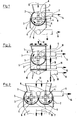
- FIG. 4 according to which the rotational body 8 formed by the carriers 2 by rotation is a cone.
- the housing 3 is adapted to this conical shape.
- the feed device 1 for feeding the cellulose hygiene articles opens into the area of the small cone diameter d, while a continuously working removal device 11 in the form of preferably several suction pipes opens into the area of the large cone diameter D.
- the mouths of these suction tubes are located near the circumference of the, since the coating waste is thrown outwards by the rotation of the drivers 2 Rotating body 8.
- the screen 6 is d. configured between the small and large cone diameter. D is at least partially arranged at a distance around the rotary body 8, as was explained with reference to the embodiment according to FIG. 1 and which also applies to all other embodiments.
- the removal device 9 with the suction pipe 10 for the pulp flocks is provided on the outside of the sieve 6, the removal device 9 with the suction pipe 10 for the pulp flocks is provided.
- the method which is carried out with this device is that the cellulose hygiene articles are fed continuously at 12 into the region of the small cone diameter d. While the pulp hygiene articles are broken up, the action of the conical rotary body 8 causes the materials to be conveyed in the axial direction along the rotary body up to the region of the large cone diameter D.
- the shredded coating waste is continuously sucked off via the discharge device 11, as indicated at 14 . At the same time, the pulp flakes are continuously sucked off via the sieve 6, as indicated at 13.
- the device of FIG. 4 Since the device of FIG. 4 is operated in this way (quantity of material supplied per unit of time, number of revolutions of the rotating component, etc.) and is constructed (sieve); that the coating waste cannot pass through the sieve 6, it is also possible to design the sieve 6 in such a way that, unlike the illustration in FIG. 4, it extends over the entire axial length of the rotary body 8.
- the embodiment according to FIG. 5 works in principle in the same way continuously as the embodiment according to FIG. 4, but differs from it in that the rotary body 8 formed by the rotation of the drivers 2 is not conical, so that the conical shape of the Rotary body 8 in Figure 4 conditional transport of the processed materials in the axial direction on which is effected.
- the drivers which are not shown individually in FIG. 5, are arranged spirally along their axis of rotation, as indicated by the spiral lines 20.
- spiral guide strips 21 are arranged on the inner wall of the housing 3 and, if appropriate, on the inside of the screen 6 at a close distance from the rotary body 8 formed by the rotation of the drivers.
- spiral guide strips 21 are arranged on the inner wall of the housing 3 and, if appropriate, on the inside of the screen 6 at a close distance from the rotary body 8 formed by the rotation of the drivers.
- there is also an axial transport of the processed materials from the feed device 1 to the discharge device 11 for the wrapping waste so that the structure of the device according to FIG. 5 corresponds
- spiral arrangement of the drivers or the arrangement of the guide strips 21 alone can be sufficient to produce a sufficient transport effect in the axial direction, so that these two measures do not necessarily have to be provided together.
- Figure 6 is shown an embodiment of a discontinuous batch operable device in which the feed is effected axially, since the Z device u Adjusts- of the rotating member 4 opens into the housing 3 axially with respect to the first
- the sieve 6 it is possible to design the sieve 6 so that it extends around the entire circumference of the rotary body formed by the rotation of the carriers 2, so that the released pulp flakes optimally via a plurality of suction tubes 10 which surround the periphery of the sieve 6 are distributed, can be suctioned off; in a corresponding manner is also an optimal suction of the coating waste by means of the suction pipes 11, which in the loading richly arranged around the circumference of the rotating body 8, possible.
- FIG. 6 can also be used in the continuously operating devices according to FIGS. 4 and 5.
- FIG. 7 shows a combination of the device according to FIG. 1 with a conventional cutting device 22.
- This cutting device can, for example, be of the type shown and described in German Offenlegungsschrift 2 704 035, and the pulp hygiene articles are thus pre-shredded.
- a gate valve 23 is provided between the cutting device 22 and the underlying device for separating the pulp and the wrappings, and a gate valve 19 is located in the suction pipe 11 for the wrapping waste.
- the gate valves 19 and 23 can otherwise be arranged and designed in the manner as explained with reference to Figure 2.
- the cutting device 22 may also be provided remotely from the device for separating the fluff pulp of the casings, in which case the ': Tr.ansport carried out the pre-comminuted pulp sanitary article between the two devices by means of conventional mechanical or pneumatic transport devices, may also be any of the be connected upstream of other devices, in particular the device according to FIG. 4 or 5.
- the axis of rotation of the rotating components 4 is otherwise designated by 24, and 25 is an arrow with which the rotation of the rotating components is indicated.
- FIG. 8 shows a fifth embodiment, the part in which the wrapping is broken is shown only half to the left of the axis line A-A.
- a rotating component 4 with rigid carriers 27, which can be completely blunt, for example made of round material, is provided in the housing 3, which is the same or similar to that according to FIG. 1, a rotating component 4 with rigid carriers 27, which can be completely blunt, for example made of round material, is provided.
- Carrier counterparts 28 are arranged stationary on the housing 3 and / or on the screen 6 on a gap to the rigid carriers 27, i.e. so that they do not come into direct contact with the drivers 27.
- driver counterparts 28 are not absolutely necessary.
- the circumference of the rotary body 8 is kept so large that cellulose hygiene articles cannot wrap it around, which can also be achieved by connecting a cutting device 22 and / or by high peripheral speed and / or by means of the driving counterparts 28.
- FIG. 8 also shows a sixth embodiment, the part of which which is different from the fifth embodiment is shown in half to the right of the axis line A-A.
- the rotating component 4 is provided with rigid knife-like drivers 26, which can also act together with driver counterparts 28.
- rigid drivers 27 are arranged on a rotating, flat component 29, preferably with increasing length of the rigid drivers 27 in the direction of increasing diameter.
- the stationary driver counterparts 28 are arranged in a gap and with a length increasing in the same direction, and in such a way that they protrude into the rotational body formed by the rotation of the drivers.
- the device works discontinuously.
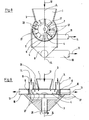
- FIG. 10 each shows half of two further embodiments, which correspond in principle to FIG. 9, but in which a longer effective distance with a relatively small diameter is achieved by the conical or conical design of the rotating component 4.
- the rotating component 4 is provided with rigid carriers 27, and stationary carrier counterparts 28 are arranged on the housing 3.
- the housing 3 is formed in the area of the small cone diameter starting as a sieve 6, partially or over the entire surface.
- the discharge device 9 is preferably placed on the housing 3 in the form of an annular channel. The cone angle of rotating component 4 and housing 3 can be different.
- the rotating component 4 is partially or completely formed as a sieve 6, preferably starting at the small diameter of the cone.
- the gap formed by the inner and outer cone, i.e. between housing 3 and rotating component 4 is formed, adjusted within limits. The device works continuously.
Abstract
Kurz zusammengefaßt wird mit der Erfindung ein Verfahren und eine Vorrichtung zur Trennung von Zellstoffflokken von deren Umhüllungen von Zellstoff-Hygieneartikeln zur Verfügung gestellt, worin die Zellstoff-Hygieneartikel von rotierenden Mitnehmern, die an einem oder mehreren rotierenden Bauteilen angeordnet sind, allein oder im Zusammenwirken mit stationären Gegenmitnehmerstücken zerschlagen und die dabei freigesetzten Zellstoffflocken über ein oder mehrere, nur die Zellstoffflocken durchlassende, Siebe abgesaugt werden, oder worin die Zellstoffflocken durch wenigstens ein Sieb abgesaugt werden, bevor die Umhüllungen so weit zerschlagen sind, daß sie durch das Sieb hindurchgehen.In brief, the invention provides a method and an apparatus for separating pulp flakes from their wrappings of cellulose hygiene articles, wherein the cellulose hygiene articles are provided by rotating drivers, which are arranged on one or more rotating components, alone or in cooperation with smash stationary counter-driver pieces and the thereby released pulp flakes are sucked off via one or more sieves which only let through the pulp flakes, or in which the pulp flakes are sucked off through at least one sieve before the wrappings are broken so far that they pass through the sieve.
Description
Die Erfindung betrifft ein Verfahren zur Trennung der Zellstofflocken von deren Umhüllungen von Zellstoff-Hygieneartikeln, welche als Ausschuß bei der Herstellung, insbesondere von Höschenwindeln, Damenbinden, Krankenbettunterlagen mit Umhüllungen, wie Kunststoffolien, Tissue, Klebestreifen, Gummibändern oder dergleichen anfallen, wobei die Zellstoff-Hygieneartikel in den Wirkungsbereich von in einem Gehäuse rotierenden Mitnehmern gefördert, die Zellstofflokken von den Mitnehmern freigesetzt sowie die freigesetzten Zellstofflocken getrennt von den Umhüllungen aus dem Gehäuse abgesaugt und die Umhüllungen aus dem Wirkungsbereich der rotierenden Mitnehmer entfernt werden. Außerdem betrifft die Erfindung eine Vorrichtung zum Durchführen dieses Verfahrens, die eine Zuführungsvorrichtung zum Zuführen der Zellstoff-Hygieneartikel in den Wirkungsbereich der rotierenden Mitnehmer und eine Abführungsvorrichtung zum Abführen, vorzugsweise Absaugen, der freigesetzten Zellstofflokken aus dem Gehäuse aufweist.The invention relates to a method for separating the pulp from their wrappings from cellulose hygiene articles, which are rejects in the manufacture, in particular of pant diapers, sanitary napkins, bedding pads with wrappings, such as plastic films, tissue, adhesive strips, rubber bands or the like, the pulp Hygiene articles are conveyed into the area of action of drivers rotating in a housing, the pulp flocks are released from the drivers and the released cellulose flakes are sucked out of the housing separately from the wrappings and the wrappings are removed from the area of action of the rotating drivers. In addition, the invention relates to a device for performing this method, which has a feed device for feeding the cellulose hygiene articles into the effective range of the rotating carriers and a discharge device for removing, preferably suctioning, the released pulp flocs from the housing.
Bekanntlich wird Holz als Rohstoff immer knapper, und die hieraus hergestellten Produkte werden daher immer teurer. Eines dieser Produkte ist hochwertig aufbereiteter Zellstoff in Form von Zellstofflocken, die zur Herstellung von Saugkissen bei Zellstoff-Hygieneartikeln benötigt werden. Ebenso verhält es sich mit Kunststoffolien und Vliesstoffen, da auch deren chemische Grundstoffe ständig Preiserhöhungen erfahren.As is well known, wood is becoming increasingly scarce as a raw material, and the products made from it are therefore becoming increasingly expensive. One of these products is high-quality processed pulp in the form of cellulose flakes, which are required for the production of absorbent pads for cellulose hygiene articles. The same applies to plastic films and nonwovens, since their chemical raw materials are constantly experiencing price increases.
Da bei der Herstellung der Zellstoff-Hygieneartikel ein nicht unbeträchtlicher Anteil an Ausschuß entsteht, ist es aufgrund der vorstehenden Verhältnisse außerordentlich wichtig, aus diesem Ausschuß, der bei der Herstellung von Zellstoff-Hygieneartikeln unvermeidbar anfällt, die Rohstoffe zurückzugewinnen, damit eine Rohstoffeinsparung ermöglicht wird.Since a not inconsiderable proportion of rejects arises in the production of the cellulose hygiene articles, it is extremely important due to the above conditions that the raw materials from this committee, which is unavoidably incurred in the production of cellulose hygiene articles recover so that raw material savings are made possible.
Das einfachste Verfahren hierfür besteht darin, die kompletten Zellstoff-Hygieneartikel insgesamt zu zermahlen, so daß also die Zellstofflocken und die Kunststoffanteile nicht voneinander getrennt werden, und die Rohstoffe in diesem zermahlenen Zustand dem Produktionskreislauf wieder zuzuführen. Da hierbei jedoch sehr viele Kunststoffanteile mit zerkleinert und den Zellstofflocken beigemischt werden, wird die Qualität der Zellstoff-Hygieneartikel hinsichtlich ihres Saugkissens herabgesetzt.The simplest method for this is to grind the entire cellulose hygiene article as a whole, so that the cellulose curls and the plastic parts are not separated from one another, and to feed the raw materials back into the production cycle in this ground state. However, since a large number of plastic parts are crushed and mixed with the pulp, the quality of the cellulose hygiene articles with regard to their absorbent pads is reduced.
Es sind außerdem auch schon Trennverfahren bekannt, die es ermöglichen, die Zellstofflocken auf mechanischem Wege von der flächigen Umhüllung weitgehend abzutrennen. Diesen Verfahren haften jedoch bestimmte wirtschaftliche und technische Nachteile an.Separation processes are also already known which make it possible to largely mechanically separate the cellulose flakes from the flat covering. However, these processes have certain economic and technical disadvantages.
So ist aus der deutschen Offenlegungsschrift 2 918 345 und der US-Patentschrift 4 303 501 ein Trennverfahren bekannt, das im wesentlichen auf einem Schwingsiebverfahren basiert: Da der zu behandelnde Ausschuß sehr voluminös ist, ist die Durchführung dieses Schwingsiebverfahrens sehr raumaufwendig, was einen wirtschaftlichen Nachteil darstellt. Außerdem muß der Ausschuß vor dem Sieben zerkleinert werden.A separation process is known from German Offenlegungsschrift 2 918 345 and US Pat. No. 4,303,501, which is essentially based on a vibrating sieve method: since the reject to be treated is very voluminous, the implementation of this vibrating sieve method is very space-consuming, which is an economic disadvantage represents. The committee must also be crushed before sieving.
Weiterhin ist in der deutschen Patentschrift 2 703 063 ein anderes Trennverfahren beschrieben, in dem die,Zellstoff-Hygieneartikel zuerst teilweise zerschnitten werden, wonach sie diskontinuierlich in den Einzugsbereich von mit hoher Umfangsgeschwindigkeit rotierenden Mitnehmern gefördert wer- . den. Hierbei werden die Hüllen aus Kunststoff auf die Mitnehmer aufgewickelt, der eingeschlossene Zellstoff wird freigesetzt und abgesaugt, und anschließend werden die Hüllen unter Zerstückelung von den Mitnehmern gelöst und abgesaugt. Dieses Verfahren besitzt aus verschiedenen Gründen einen geringen Wirkungsgrad, da die Mitnehmer nach Eingabe einer geringen Menge von Zellstoff-Hygieneartikeln sehr schnell von den Hüllen umwickelt und damit wirkungslos werden. Daher kann pro Arbeitszyklus immer nur eine geringe Menge an Zellstoff-Hygieneartikeln verarbeitet werden. Es ist weiterhin zu bedenken, daß der gesamte Arbeitszyklus aus drei Arbeitsschritten besteht, und zwar beinhaltet der erste Arbeitsschritt das Zerschneiden und Einfüllen der Stücke der Zellstoff-Hygieneartikel in den Wirkungsbereich der Mitnehmer, wobei letztere die Zellstofflocken freisetzen und die Hüllen auf den Mitnehmern aufgewickelt werden; der zweite Arbeitsschritt dient lediglich zum Absaugen der Flocken; und erst dann kann der dritte Arbeitsschritt durchgeführt werden, der im Zerschneiden der aufgewickelten Hüllen und deren Absaugung besteht. Durch diese verhältnismäßig vielen Arbeitsschritte kommt es zwangsläufig zu einer noch weiteren Verschlechterung des Wirkungsgrads.Furthermore, another separation method is described in the
Schließlich ist aus der deutschen Offenlegungsschrift . 2 704 035 ein Trennverfahren bekannt, dessen wesentliche Merkmale darin bestehen, daß die Zellstoff-Hygieneartikel zunächst in einer Schneidmühle zerkleinert werden, wobei die Schneidmühle an ihrem Ausgang ein Sieb aufweist, welches eine starke Zerkleinerung in dem für das Verfahren notwendigen Maße ermöglicht. Zum Ansaugen des zerschnittenen Gutes durch das Sieb ist der Schneidmühle ein Ventilator nachgeordnet, der auch zunächst für den weiteren pneumatischen Transport sorgt. Bei der weiteren Durchführung des Verfahrens erfolgt eine Abtrennung eines großen Teils der Luft des Luft-Transportgut-Gemisches, was durch einen Luftabscheider erreicht wird. Der Ausgang des Luftabscheiders ist mit dem Inneren eines Siebzylinders verbunden, in dessen zylindrischer Achse auf einer Welle starr angeordnete Rührarme rotieren. Der Siebzylinder sitzt in einem Gehäuse, welches im Abstand von dem Siebzylinder vorgesehen ist. Dieses Gehäuse fängt auch jene Zellstofflocken auf, die durch die Bewegung der Rührarme durch den Siebzylinder hindurchtreten. An dem Ende des Siebzylinders, das dem Eintritt der Zellstofflokken gegenüberliegt, wird ein Gemisch von Umhüllungsteilen und Zellstofflocken aufgefangen, welche nicht durch die Siebwandung hindurchgetreten sind. Dieses Gemisch wird dann in eine weitere, identische Siebeinrichtung überführt, die sich allenfalls durch eine andere Siebmäschenweite unterscheidet. Auf diese Weise können kaskadenartig mehrere Zylindersiebanlagen hintereinander angeordnet werden.Finally, is from the German patent application. 2 704 035 a separation process is known, the main features of which are that the cellulose hygiene articles are first comminuted in a cutting mill, the cutting mill having a sieve at its outlet, which enables strong comminution to the extent necessary for the process. To suck the cut material through the sieve, the cutting mill is followed by a fan, which also initially provides for further pneumatic transport. When the method is carried out further, a large part of the air of the air / cargo mixture is separated, which is achieved by an air separator. The outlet of the air separator is connected to the inside of a sieve cylinder, in the cylindrical axis of which stirrer arms rigidly arranged on a shaft animals. The screen cylinder sits in a housing which is provided at a distance from the screen cylinder. This housing also catches those pulp that pass through the sieve cylinder due to the movement of the stirring arms. At the end of the sieve cylinder, which is opposite the entrance of the pulp flocks, a mixture of wrapping parts and pulp flakes is collected, which have not passed through the sieve wall. This mixture is then transferred to a further, identical screening device, which differs at most by a different mesh size. In this way, several cylinder screen systems can be arranged in a cascade.
Diesem Verfahren haften erhebliche Mängel an. So ist zum Beispiel der räumliche Aufwand zu seiner Durchführung noch größer als bei dem Schwingsiebverfahren nach der vorgenannten deutschen Offenlegungsschrift 2 918 345 bzw. der US-Patentschrift 4 303 501. Das Trennverfahren nach der deutschen Offenlegungsschrift 2 704 035 umfaßt mindestens vier Arbeitsschritte, wenn man von nur einem einzigen Siebzylinder ausgeht. Bei mehreren Siebzylindern ergeben sich leicht sieben oder mehr Arbeitsschritte. Der erste Arbeitsschritt beinhaltet die Beschickung, das Vorschneiden und das Absaugen durch das Sieb der Schneidmühle. Der zweite Arbeitsschritt betrifft das Luftabscheiden und den Transport zum Inneren der ersten Siebtrommel. Der dritte Arbeitsschritt beinhaltet das Sieben der Materialien, die durch die Maschen. des Siebes hindurchtreten können. Der vierte Arbeitsschritt stellt die Sammlung und Übergabe der Mischmaterialien an den nächsten Siebzylinder dar. Anschließend können der vorerwähnte dritte und vierte Arbeitsschritt mehrfach wiederholt werden. Die Schwierigkeit dieses Verfahrens besteht jedoch nicht nur in.dem erheblichen Raumbedarf zu seiner Durchführung, sondern noch nachteiliger ist es, daß in der Praxis keine zufriedenstellende Trennung der Zellstofflocken von ihren Umhüllungen mit diesem Verfahren zu erreichen ist Das liegt insbesondere daran, daß die flächigen Umhüllungsteile an die Innenseite des Siebzylinders gepreßt werden, da eine völlige Abtrennung der Luft am Ausgang des Luftabscheiders nicht möglich ist, denn ein Teil der Luft wird zum Zweck des weiteren Transports benötigt. Weiter haftet diesem Verfahren der Mangel an, daß nicht nur Zellstofflokken sondern auch kleingeschnitzelte Umhüllungsteile in größerer Menge durch die Siebtrommeln hindurchtreten, ohne daß die dadurch entstehende Mischung noch einmal nachbehandelt wird. Der Einsatz dieses Verfahrens ist also in der Praxis nicnt in zufriedenstellender Weise möglich.There are significant shortcomings in this process. For example, the space required to carry it out is even greater than with the vibrating sieve method according to the aforementioned German Offenlegungsschrift 2 918 345 or US Pat. No. 4,303,501. The separation method according to the
Aufgabe der Erfindung ist es demgegenüber insbesondere, ein Verfahren und eine Vorrichtung der eingangs genannten Art zu schaffen, die einen verhältnismäßig geringen Raumbedarf hat und einen relativ großen Wirkungsgrad besitzen, wobei das Verfahren aus möglichst wenigen Arbeitsschritten bestehen und auch dann mit den obigen Vorteilen durchführbar sein soll, wenn auf eine Vorzerkleinerung, welche räumlich vor dem eigentlichen Trennverfahren erfolgt, verzichtet wird.In contrast, the object of the invention, in particular, is to provide a method and a device of the type mentioned at the outset which have a relatively small space requirement and have a relatively high degree of efficiency, the method comprising as few work steps as possible and also being able to be carried out with the above advantages should, if a pre-shredding, which takes place spatially before the actual separation process, is dispensed with.
Diese Aufgabe wird, ausgehend von einem Verfahren der eingangs genannten Art, erfindungsgemäß dadurch gelöst, daß die Zellstoff-Hygieneartikel von den rotierenden Mitnehmern, die an einem oder mehreren rotierenden Bauteilen angeordnet sind, allein oder in Zusammenwirken mit stationären Mitnehmergegenständen im wesentlichen zersc;hlagen.werden, und daß die dabei freigesetzten Zellstofflocken über ein Sieb abgesaugt werden, wobei entweder die Umhüllungen nur so grob zerschlagen werden, daß sie nicht durch das Sieb hindurchgehen, oder'die Zellstofflocken über das Sieb abgesaugt werden, bevor die Umhüllungen so fein zerschlagen sind, daß sie durch das Sieb hindurchgehen.Starting from a method of the type mentioned at the outset, this object is achieved according to the invention in that the cellulose hygiene articles are essentially broken up by the rotating drivers, which are arranged on one or more rotating components, alone or in cooperation with stationary driver objects. and that the pulp lumps released in this process are sucked off through a sieve, the wrappings either being only roughly broken so that they do not pass through the sieve, or the pulp flakes being sucked off through the sieve before the wrappings are broken up so finely, that they go through the sieve.
Die mit der Erfindung vorgeschlagene Vorrichtung zum Durchführen dieses Verfahrens zeichnet sich dadurch aus, daß die scharf oder stumpf ausgebildeten Mitnehmer, die an einem oder mehreren rotierenden Bauteilen beweglich oder starr angeordnet sind, allein oder zusammen mit stationären, beweglich oder starr vorgesehenen sowie scharf oder stumpf ausgebildeten Mitnehmergegenstücken so angeordnet und/oder ausgebildet sind, daß sie die Zellstoff-Hygieneartikel im wesentlichen zerschlagen, und daß zumindest ein Sieb ganz oder teilweise um den durch die Rotation der Mitnehmer gebildeten Rotationskörper herum in einem derart geringen Abstand vorgesehen ist, daß auf der rauhen oder glatten Innenseite des Siebes befindliche zu trennende Materialien von den Mitnehmern erfaßbar sind.The device proposed by the invention for carrying out this method is characterized in that the sharply or bluntly formed drivers, which are movably or rigidly arranged on one or more rotating components, alone or together with stationary, movably or rigidly provided and sharply or bluntly Trained counterparts are arranged and / or designed such that they essentially break up the cellulose hygiene articles, and that at least one sieve is provided in whole or in part around the rotating body formed by the rotation of the carriers at such a small distance that the rough one or smooth inside of the sieve to be separated materials can be detected by the drivers.
Es wurde nämlich überraschenderweise gefunden, daß es durch dieses Verfahren und mit dieser Vorrichtung, worin die rotierenden, starren oder beweglichen Mitnehmer allein oder zusammen mit den stationären, starren oder beweglichen Mitnehmergegenstücken ein Wirkungsfeld bilden, in dessen Lücken sich die zerrissenen Zellstoff-Hygieneartikel ausreichend ausbreiten können, ein Zerschlagen der Umhüllungen erreicht wird, anstatt daß sich die Umhüllungen um die Mitnehmer herumwickeln und diese in kurzer Zeit wirkungslos machen, wie es bei dem Verfahren und der Vorrichtung nach der weiter ober erörterten deutschen Patentschrift P 2 703 063 der Fall ist. Bei diesem Zerschlagen kommt es, wie weiter bei den Untersuchungen, die zur::vorliegenden Erfindung geführt haben, gefunden wurde, dazu, daß der bei dem Zerschlagen der Umhüllungen entstehende Umhüllungsabfall gegenüber den Zellstofflocken zunächst relativ grobkörnig ist und bleibt, so daß beim Absaugen der Zellstofflocken durch ein entsprechendes Sieb eine hervorragende, praktisch quantitative Trennung von Zellstofflocken.und Umhüllungen erzielt wird. Das konnte durch Versuche mit besonders markant gefärbten Umhüllungen nachgewiesen werden. Diese ausgezeichnete Trennung erfolgt aufgrund eines weiteren Effekts nicht nur in dem Sinn, daß die abgetrennten Zellstofflocken frei von Umhüllungswerkstoffen sind, sondern auch in dem Sinn, daß das abgetrennte Umhüllungsmaterial, bei dem es sich um Kunststoff handelt, seinerseits weitgehend cellulosefrei ist. Es wurde nämlich festgestellt, daß im Gegensatz zu dem Verfahren nach der deutschen Patentschrift 2 703 063 bei der Erfindung auch eine Zerfaserung des Tissue erfolgt, bei dem es sich um Cellulosepapier ohne Binder handelt. Dadurch wird nicht nur verhindert, daß das Tissuematerial das Umhüllungsmaterial "verunreinigt", sondern das Tissuematerial wird in vorteilhafter Weise dem Herstellungsprozeß als flüssigkeitsaufnahmefähiger Faserstoff zugeführt, ohne daß eine Qualitäts- änderung des Saugkissenmaterials stattfindet. Das abgetrennte Umhüllungsmaterial kann wegen seiner weitgehenden Cellulosefreiheit in sehr vorteilhafter Weise der Wiederverwendung zugeführt werden.Surprisingly, it was found that this process and this device, in which the rotating, rigid or movable carriers, alone or together with the stationary, rigid or movable carrier counterparts, form a field of action, in the gaps of which the torn pulp hygiene articles spread sufficiently can, a shattering of the wrappings is achieved instead of the wrappings wrapping around the drivers and rendering them ineffective in a short time, as is the case with the method and the device according to the
Diese Vorteile ergeben sich besonders ausgeprägt durch eine bewegliche Anordnung der Mitnehmer an dem rotierenden Bauteil, zum Beispiel an einer Welle, in welchem Falle eine besonders hervorragende Wirkung erzielt wird, und zwar auch ohne Mitnehmergegenstücke.These advantages are particularly pronounced through a movable arrangement of the drivers on the rotating component, for example on a shaft, in which case a particularly excellent effect is achieved, even without driver counterparts.
Hinsichtlich des vorstehenden Wirkungsfeldes ist zu beachten, daß es nicht zu dicht ist, denn ein zu dichtes Wirkungsfeld, in dem sich also die zerrissenen Zellstoff-Hygieneartikel nicht ausreichend ausbreiten können, hätte ein Verstopfen und/oder ein Aufreißen der Umhüllungen in zu kleine Stücke bei gleichzeitig hoher Leistungsaufnahme des Antriebes zur Folge.With regard to the above field of action, it should be noted that it is not too dense, because a too dense field of action, in which the torn pulp hygiene articles cannot spread sufficiently, would lead to clogging and / or tearing of the wrappings into pieces that are too small at the same time high power consumption of the drive.
Weiterhin haben das Verfahren und die Vorrichtung nach der Erfindung nur einen verhältnismäßig geringen Raumbedarf bei relativ hohem Wirkungsgrad.Furthermore, the method and the device according to the invention have only a relatively small space requirement with a relatively high efficiency.
Das Verfahren nach der Erfindung läßt sich sowohl diskontinuierlich als auch kontinuierlich durchführen; im ersteren Fall ergibt sich gegenüber dem Stand der Technik der zusätzliche Vorteil, daß das genannte Verfahren aus nur zwei Arbeitsschritten besteht, wobei im ersten Arbeitsschritt die, vorzugsweise nichtvorzerkleinerten, Zellstoff-Hygieneartikel diskontinuierlich chargenweise zu den Mitnehmern zugeführt, zerschlagen und dabei die freigesetzten Zellstoffflocken abgesaugt werden, während im zweiten Arbeitsschritt daran anschließend die zerschlagenen Umhüllungen vor Zuführung der nächsten Charge von Zellstoff-Hygieneartikeln aus dem Wirkungsbereich der Mitnehmer entfernt werden; für diesen zweiten Arbeitsschritt ist nur eine kurzzeitige Unterbrechung erforderlich, so daß der hohe Wirkungsgrad nicht beeinträchtigt wird.The process according to the invention can be carried out batchwise or continuously; In the former case, there is the additional advantage over the prior art that the above-mentioned method consists of only two work steps, with the preferably non-comminuted, pulp hygiene articles being fed batchwise to the drivers in batches, smashing and suctioning off the released cellulose flakes are removed, while in the second step the shattered wrappings are then removed from the area of action of the drivers before the next batch of cellulose hygiene articles is supplied; only a brief interruption is required for this second work step, so that the high efficiency is not impaired.
Bei der kontinuierlichen Ausführung des Verfahrens werden gemäß der Erfindung die Zellstoff-Hygieneartikel in den einen Endbereich eines von den Mitnehmern durch Rotation gebildeten Rotationskörpers kontinuierlich zugeführt, während des Zerschlagens in Axialrichtung längs des Rotationskörpers gefördert und die zerschlagenen Umhüllungen am anderen Endbereich des Rotationskörpers kontinuierlich abgeführt, vorzugsweise abgesaugt, während die Zellstofflocken in dem Zwischenbereich zwischen den beiden Endbereichen und gegebenenfalls in einem oder beiden Endbereichen des Rotationskörpers kontinuierlich abgesaugt werden.In the continuous execution of the method, according to the invention, the cellulose hygiene articles are continuously fed into one end region of a rotary body formed by the carriers by rotation, conveyed along the rotary body during the breaking in the axial direction, and the broken wrappings are continuously removed at the other end region of the rotary body, preferably suctioned off, while the pulp flakes are continuously sucked off in the intermediate region between the two end regions and optionally in one or both end regions of the rotary body.
Das Fördern in Axialrichtung längs des Rotationskörpers kann durch entsprechende Ausbildung'des Rotationskörpers selbst und/oder entsprechende Anordnung der Mitnehmer entlang der Rotationsachse und/oder durch entsprechende Ausbildung des von dem Gehäuse und dem Sieb gebildeten Mantels um den Rotationskörper herum erzielt werden. Die erstere Möglichkeit läßt sich in der Weise verwirklichen, daß der von den Mitnehmern durch Rotation gebildete Rotationskörper in seinem Durchmesser fortlaufend abnimmt, insbesondere ein Kegel ist, während sich die letzteren beiden Möglichkeiten dadurch verwirklichen lassen, daß die Mitnehmer entlang ihrer Rotationsachse spiralig angeordnet sind und/oder in engem Abstand von dem durch die Rotation der Mitnehmer gebildeten Rotationskörper spiralförmige Führungsleisten vorgesehen sind. Im ersteren Fall mündet die Zuführungsvorrichtung im Bereich des kleinen Durchmessers, während im Bereich des großen Durchmessers eine kontinuierlich arbeitende Abführungsvorrichtung für die zerschlagenen Umhüllungen mündet; und in den letzteren beiden Fällen ist die Anordnung so, daß am Anfang des durch die spiralförmige Anordnung der Mitnehmer und/oder Führungsleisten gebildeten Transportwegs die Zuführungsvorrichtung und am Ende desselben eine kontinuierlich arbeitende Abführungsvorrichtung für die zerschlagenen Umhüllungen mündet. In allen diesen Fällen ist das Sieb, vorzugsweise zwischen dem Anfang und dem Ende des Transportwegs, der durch die axiale Erstreckung des Rotationskörpers festgelegt ist, ganz oder teilweise um den Rotationskörper angeordnet.The conveying in the axial direction along the rotary body can be achieved by appropriate design of the rotary body itself and / or corresponding arrangement of the drivers along the axis of rotation and / or by appropriate design of the casing formed by the housing and the sieve around the rotary body. The former possibility can be realized in such a way that the rotational body formed by the drivers by rotation decreases in diameter continuously, in particular is a cone, while the latter two possibilities can be realized in that the drivers are arranged spirally along their axis of rotation and / or spiral guide strips are provided at a close distance from the rotary body formed by the rotation of the drivers. In the former case, the feed device opens out in the area of the small diameter, while in the area of the large diameter a continuously working removal device for the broken sheaths opens out; and in the latter two cases the arrangement is such that at the beginning of the transport path formed by the spiral arrangement of the drivers and / or guide strips the feed device and at the end of the same a continuously working discharge device for the broken wrappings opens. In all these cases, the screen, preferably between the beginning and the end of the transport path, which is defined by the axial extent of the rotating body, is arranged in whole or in part around the rotating body.
Im Falle einer diskontinuierlichen Vorrichtung hat der durch die Rotation der Mitnehmer gebildete Rotationskörper keine axiale Transportwirkung, und die Zuführungsvorrichtung sowie die Abführungsvorrichtung für die Zellstofflokken einerseits und eine Abführungsvorrichtung für die zerschlagenen Umhüllungen andererseits sind abwechselnd diskontinuierlich betreibbare Vorrichtungen.In the case of a discontinuous device, the rotary body formed by the rotation of the drivers has no axial transport action, and the feed device and the discharge device for the pulp locos on the one hand and a discharge device for the broken wrappings on the other hand are devices which can be operated alternately discontinuously.
In allen Fällen können die Zellstofflocken über mehrere hintereinander angeordnete Siebe abgesaugt werden, weiter ist es in allen Fällen möglich, die Zuführungsvorrichtung bezüglich des von den Mitnehmern gebildeten Rotationskörpers als axiale Zuführungsvorrichtung auszubilden, und schließlich kann in jedem Falle vor oder in der Zuführungsvorrichtung eine Schneidvorrichtung vorgesehen sein. Stets erfolgt das Zerschlagen der Zellstoff-Hygieneartikel und das Trennen der Stoffe, aus denen diese bestehen, in einem einzigen Gehäuse bei geringem Raumaufwand.In all cases, the pulp can be sucked off via a plurality of sieves arranged one behind the other, furthermore it is possible in all cases to design the feed device as an axial feed device with respect to the rotary body formed by the carriers, and finally in any case a cutting device can be provided in front of or in the feed device be. Always done the smashing of the cellulose hygiene articles and the separation of the materials from which they are made in a single housing with little space requirement.
Das verwendete Sieb kann insbesondere eines der folgenden sein:
- (a) ein Blechsieb mit glatter Wirkfläche;
- (b) ein Blechsieb mit rauher Wirkfläche, bei dem die durch--die Lochung verbliebenen Stege oder Randzonen (Wulste) der Lochung ganz oder teilweise deformiert sind, vorzugsweise ein Schlitz-, Rund- oder Dreieck-Brückenlochsieb oder ein Sieb mit Raspellochungen, bei dem die Lochung mittels Durchdrücken des Materials mit spitzem Dorn hergestellt ist;
- (c) ein Drahtsieb aus Drahtgeflecht oder Drahtgewebe, das eine rauhe Oberflächenstruktur aufweist; oder
- (d) ein Drahtsieb oder Drahtgeflecht mit glatter Wirkfläche, die beispielsweise durch Walzen oder Pressen des Siebes geglättet worden ist.
- (a) a sheet metal screen with a smooth active surface;
- (b) a sheet metal sieve with a rough active surface, in which the webs or edge zones (beads) of the perforation remaining through the perforation are deformed in whole or in part, preferably a slotted, round or triangular bridge perforated sieve or a sieve with rasp perforations the perforation is made by pushing the material with a pointed mandrel;
- (c) a wire mesh or wire mesh wire screen that has a rough surface structure; or
- (d) a wire screen or wire mesh with a smooth active surface that has been smoothed, for example, by rolling or pressing the screen.
Die Wirkfläche des Siebes ist die den Mitnehmern zugewandte Siebfläche, die auch als Innenfläche bezeichnet wird. Die Angabe "glatte" Wirkfläche bezieht sich auf die Fläche der Stege oder Brücken zwischen den Sieböffnungen.The active surface of the sieve is the sieve surface facing the drivers, which is also referred to as the inner surface. The indication "smooth" effective area refers to the area of the webs or bridges between the sieve openings.
Weiter kann die Vorrichtung so ausgebildet sein, daß die Mitnehmergegenstücke in den durch die Rotation der Mitnehmer gebildeten Rotationskörper eingreifen oder nicht eingreifen.Furthermore, the device can be designed such that the driver counterparts engage or do not engage in the rotational body formed by the rotation of the drivers.
Schließlich zeichnet sich eine weitere bevorzugte Ausführungsform dadurch aus, daß
- (a) die Mitnehmer auf einem ebenen rotierenden Bauteil angeordnet sind und daß vorzugsweise die Mitnehmer und/oder die Mitnehmergegenstücke so ausgebildet sind, daß ihre Länge in Richtung des größeren Durchmessers zunimmt; oder daß
- (b) die Mitnehmer auf einem konischen rotierenden Bauteil angeordnet sind, wobei entweder das konische Bauteil oder das Gehäuse ganz oder teilflächig als Sieb ausgebildet ist, und in letzterem Falle die Abführungsvorrichtung für die Zellstofflocken vorzugsweise ringkanalförmig auf dem Gehäuse vorgesehen ist.
- (a) the drivers are arranged on a flat rotating component and that preferably the drivers and / or the driver counterparts are designed such that their length increases in the direction of the larger diameter; or that
- (b) the drivers are arranged on a conical rotating component, wherein either the conical component or the housing is formed entirely or partially as a sieve, and in the latter case the removal device for the pulp flocks is preferably provided on the housing in the form of an annular channel.
Die Erfindung sei nachfolgend anhand einiger in den Figuren 1 bis 7 der Zeichnung im Prinzip dargestellter, besonders bevorzugter Ausführungsformen näher erläutert; es zeigen:
- Figur 1 eine erste Ausführungsform einer Vorrichtung nach der Erfindung, die eine Grundausführung darstellt;
Figur 2 eine Abwandlung der Grundausführung nach Figur 1, in der ein zusätzliches Sieb und mehrere Absperrschieber vorgesehen sind;Figur 3 eine Abwandlung der Grundausführung nach Figur 1, in welcher die rotierenden Mitnehmer und das als Welle ausgebildete rotierende Bauteil, an dem die Mitnehmer gemäß Figur 1 beweglich angeordnet sind, in doppelter Ausführung horizontal nebeneinander vorgesehen sind;- Figur 4 eine zweite Ausführungsform einer Vorrichtung nach der Erfindung, die kontinuierlich arbeitet, wobei die Mitnehmerenden konisch angeordnet sind, so daß sich ein kegelförmiger Aufbau ergibt;
Figur 5 eine dritte Ausführungsform einer erfindungsgemäßen Vorrichtung, die ebenfalls kontinuierlich arbeitet, wobei jedoch die Mitnehmer eine spiralige Anordnung bilden und/oder eine spiralige Anordnung von Führungsleisten auf der Innenwandung des Gehäuses vorgesehen ist; wobei inFigur 5 sowohl die spiralige Anordnung als auch die Führungsleisten eingezeichnet sind;Figur 6 eine vierte Ausführungsform der Erfindung, die diskontinuierlich arbeitet, wobei die Beschickung axial erfolgt und um die Mitnehmer herum ein Zylindersieb angeordnet ist oder ein oder mehrere Siebsegmente vorgesehen sind;Figur 7 eine Kombination einer an sich bekannten Schneidvorrichtung, die der Grundausführung nach Figur 1 unmittelbar vorgeordnet ist, die jedoch auch einer der anderen Ausführungsformen der erfindungsgemäßen Vorrichtung unmittelbar vorgeordnet sein kann; die Schneidvorrichtung kann auch entfernt von der eigentlichen erfindungsgemäßen Vorrichtung aufgestellt sein, wobei dann der Transport der durch die Schneidvorrichtung vorzerschnittenen Zellstoff-Hygieneartikel mit einer herkömmlichen mechanischen oder pneumatischen Vorrichtung vorgenommen werden kann;Figur 8 eine fünfte und sechste Ausführungsform der Erfindung, die sich hinsichtlich der Mitnehmer und bezüglich des Vorsehens von Mitnehmergegenstücken unterschei- den, wobei diese unterschiedlichen Teile jeweils auf einer seitlichen Hälfte der Figur 8 dargestellt sind;Figur 9 eine siebente Ausführungsform der Erfindung; undFigur 10 eine achte und neunte Ausführungsform der Erfindung, jeweils hälftig von der Mittellinie.
- Figure 1 shows a first embodiment of a device according to the invention, which is a basic embodiment;
- Figure 2 shows a modification of the basic version of Figure 1, in which an additional screen and a plurality of gate valves are provided;
- 3 shows a modification of the basic embodiment according to FIG. 1, in which the rotating drivers and the rotating component designed as a shaft, on which the drivers according to FIG. 1 are movably arranged, are provided horizontally next to one another in duplicate;
- Figure 4 shows a second embodiment of a device according to the invention, which operates continuously, the driver ends are arranged conically, so that there is a conical structure;
- Figure 5 shows a third embodiment of a device according to the invention, which also works continuously, but the drivers bil a spiral arrangement the and / or a spiral arrangement of guide strips is provided on the inner wall of the housing; 5 shows both the spiral arrangement and the guide strips;
- FIG. 6 shows a fourth embodiment of the invention, which operates discontinuously, the loading taking place axially and a cylinder screen being arranged around the drivers or one or more screen segments being provided;
- FIG. 7 shows a combination of a cutting device known per se, which is directly upstream of the basic embodiment according to FIG. 1, but which can also be upstream of one of the other embodiments of the device according to the invention; the cutting device can also be set up remotely from the actual device according to the invention, in which case the pulp hygiene articles pre-cut by the cutting device can then be transported using a conventional mechanical or pneumatic device;
- Figure 8 is a fifth and sixth embodiment of the invention, the carrier and with respect to the provision of Mitnehmergegenstücken in terms under failed -, where these different parts are each represented on a side half of the figure 8 the;
- Figure 9 shows a seventh embodiment of the invention; and
- Figure 10 shows an eighth and ninth embodiment of the invention, each half from the center line.
Im übrigen sind in allen Figuren der Zeichnung gleichartige oder entsprechende Bauteile weitgehendst mit den gleichen Bezugszeichen bezeichnet und daher nicht in jedem Falle erneut erläutert.Otherwise, similar or corresponding components are largely the same in all figures of the drawing Reference numerals denoted and therefore not explained again in every case.
Es sei nun zunächst auf die Figur 1 Bezug genommen, die eine erste Ausführungsform einer Vorrichtung, die es ermöglicht, Zellstoff-Hygieneartikel in der Weise zu verarbeiten, daß die Zellstofflocken von den Umhüllungen getrennt werden, zeigt.Reference is first made to FIG. 1, which shows a first embodiment of a device which makes it possible to process cellulose hygiene articles in such a way that the cellulose flakes are separated from the wrappings.
Diese Ausführungsform kann auch als Grundausführung bezeichnet werden, da sie praktisch die einfachste Ausführungsform ist.This embodiment can also be referred to as the basic embodiment, since it is practically the simplest embodiment.
Im einzelnen besitzt die Vorrichtung nach Figur 1 eine Zuführungsvorrichtung 1 zum Zuführen der nichtdargestellten Zellstoff-Hygieneartikel. Diese Zuführungsvorrichtung 1 ist in der dargestellten Ausführungsform als Trichter ausgebildet, sie kann jedoch auch ein zylindrisches oder sonstiges Rohr sein, wobei diese Zuführungsvorrichtung 1 außerdem noch eine nichtdargestellte Transportvorrichtung, wie beispielsweise ein Luftgebläse zum Erzeugen eines die Zellstoff-Hygieneartikel fördernden Luftstroms, ein endloses Förderband, eine Rutsche o.dgl. umfassen kann. Diese Zuführungsvorrichtung dient dazu, die Zellstoff-Hygieneartikel in den Wirkungsbereich von Mitnehmern 2 zu fördern, die in einem an die Zuführungsvorrichtung 1 unmittelbar anschließenden Gehäuse 3 rotieren.In detail, the device according to FIG. 1 has a feed device 1 for feeding the cellulose hygiene articles, not shown. This feed device 1 is designed in the embodiment shown as a funnel, but it can also be a cylindrical or other tube, this feed device 1 also being a transport device, not shown, such as an air blower for generating an air flow that promotes the cellulose hygiene articles, an endless conveyor belt , a slide or the like. may include. This feed device serves to convey the cellulose hygiene articles into the area of action of
Die Mitnehmer 2 sind beweglich an einem als Welle ausgebildeten rotierenden Bauteil 4 angeordnet. Diese Mitnehmer 2 können beispielsweise längliche Körper, zum Beispiel Stäbe, aus einem schlagfesten Material, wie beispielsweise aus Stahl, sein. Die Mitnehmer 2 sind jeweils mittels einer Mitnehmeraufhängung 5, welche eine Relativbewegung zwischen den Mitnehmern 2 und dem rotierenden Bauteil 4 ermöglicht, an letzterem angebracht. Diese Mitnehmeraufhängung 5 kann ein an jedem Mitnehmer 2 oder je an einer Gruppe von Mitnehmern 2 angebrachter Mitnehmerbolzen sein, der vorzugsweise parallel zu der Drehachse des rotierenden Bauteils 4 angeordnet ist und um dessen Achse sich der Mitnehmer oder die Gruppe von Mitnehmern frei schwenken kann. Es ist jedoch auch möglich, die Mitnehmeraufhängung 5 als Mitnehmergelenk auszubilden, wobei entweder jeder einzelne Mitnehmer 2 oder je eine Gruppe von mehreren Mitnehmern 2 ein solches Mitnehmergelenk besitzt, dessen Gelenkachse vorzugsweise parallel zur Drehachse des rotierenden Bauteils 4 verläuft. Die Mitnehmergelenke können auch als Kugelgelenke oder sonstige, ein Schwenken in mehreren Richtungen ermöglichende Gelenke ausgebildet sein.The
Ein Sieb 6 ist um den durch die mittels des Pfeils 7 angedeutete Rotation der Mitnehmer 2 gebildeten Rotationskörper 8 herum angeordnet, und zwar so, daß es sich um den halben Umfang dieses Rotationskörpers 8 herum erstreckt. Das Sieb 6 kann sich auch um einen kleineren oder größeren Winkelbereich als 1800 um den Umfang des Rotationskörpers 8 herum erstrecken, insbesondere kann es sich vollständig um den Rotationskörper 8 herum erstrecken, wenn das die konstruktive Ausbildung der Zuführungsvorrichtung 1 zuläßt, zum Beispiel dann, wenn die Zuführungsvorrichtung, wie in Figur 6 dargestellt, eine axiale Zuführungsvorrichtung ist.A
Wesentlich ist, daß die Mitnehmer 2 in einem derart geringen Abstand von dem Umfang des Rotationskörpers 8 vorgesehen sind, daß zu trennende Materialien, also die Materialien der Zellstoff-Hygieneartikel, noch von den Mitnehmern 2 erfaßt werden können, wenn sie sich auf der den Mitnehmern zugewandten Seite des Siebes 6, die als Innenseite bezeichnet ist, befinden. Es ist hierbei zu beachten, daß dieser "geringe Abstand" keineswegs so klein sein muß, wie es beispielsweise die Dicke der Zellstofflocken ist, sondern daß dieser "geringe Abstand" gleich der oder kleiner als die Dicke eines Materialkeils ist, der aus den zu trennenden Materialien besteht und den die Mitnehmer im Betrieb der Vorrichtung vor sich her schieben, so daß er an der Innenseite des Siebes 6 vorbeigleitet. Die Einhaltung dieses "geringen Abstands" ist deswegen äußerst wichtig, weil sonst das Sieb 6 kurz nach Inbetriebnahme cer Vorrichtung verstopft werden würde.It is essential that the
Auf der den Mitnehmern 2 abgewandten Seite des Siebes 6, die hier auch als Außenseite bezeichnet wird, ist eine Abführungsvorrichtung 9 zum Abführen der freigesetzten Zellstofflocken aus dem Gehäuse 3 vorgesehen. Diese Abführungsvorrichtung 9 kann, wie dargestellt, ein Trichter sein und ein Absaugrohr 10 für die Zellstofflocken umfassen, das am verjüngten Ende des Trichters in letzteren mündet.On the side of the
Weiterhin ist eine Abführungsvorrichtung 11 für die zerschlagenen Umhüllungen (also den Umhüllungsabfall) so vorgesehen, daß sie, bezogen auf die Strömungsrichtung der freigesetzten Zellstofflocken, stromaufwärts vom Sieb 6 in das Innere des Gehäuses 3 mündet, und zwar vorzugsweise in unmittelbarer Nähe des Wirkungsbereichs der Mitnehmer 2. Diese Abführungsvorrichtung 11 ist vorliegend als Absaugrohr ausgebildet.Furthermore, a
Es sei nun anhand der Betriebsweise der Vorrichtung nach Figur 1 die Durchführung einer bevorzugten Ausführungsform des Verfahrens zur Trennung der Zellstofflocken von deren Umhüllungen erläutert:
- (1) In einem ersten Verfahrensschritt werden die aufzuarbeitenden Zellstoff-Hygieneartikel in einer Charge durch die Zuführungsvorrichtung 1 zu
den rotierenden Mitnehmehrn 2 zugeführt; diese Zuführung istdurch den Pfeil 12 angedeutet. Hierbei werden die Zellstoff-Hygieneartikel durch die Mitnehmer zerschlagen und die darin befindlichen Zellstofflocken über dieAbführungsvorrichtung 9durch das Absaugrohr 10 laufend abgesaugt, wiedurch den Pfeil 13 angedeutet ist. Während dieses Verfahrensschritts ist dieAbführungsvorrichtung 11 nicht in Betrieb, da andernfalls die freigesetzten Zellstoffflocken auch durch diese Abführungsvorrichtung mit abgesaugt werden würden. Der erste Verfahrensschritt wird so lange betrieben, daß praktisch alle Zellstofflocken freigesetzt-werden, jedoch nur so lange, daß der Umhüllungsabfall nicht zu feinkörnig wird, also noch nicht durchdas Sieb 6 durchgehen kann, sondern sich vielmehr im Inneren des Gehäuses ansammelt. - (2) Im zweiten Verfahrensschritt wird die Zuführung der Zellstoff-Hygieneartikel kurzzeitig gestoppt, und die zerschlagenen Umhüllungen werden mittels der Abführungsvorrichtung 11 aus dem Wirkungsbereich der rotierenden Mitnehmer 2 entfernt, wie
durch den Pfeil 14 angedeutet ist. Hierzu ist eine nur verhältnismäßig sehr kurze Unterbrechung der Beschickung der Vorrichtung mit Zellstoff-Hygieneartikeln erforderlich, so daß der hohe Wirkungsgrad dieser Vorrichtung dadurch praktisch nicht beeinträchtigt wird.
- (1) In a first process step, the pulp hygiene articles to be processed are fed in one batch through the feed device 1 to the rotating
carriers 2; this feed is through thearrow 12 indicated. In this case, the cellulose hygiene articles are smashed by the drivers and the cellulose flakes therein are continuously sucked off via thedischarge device 9 through thesuction pipe 10, as indicated by thearrow 13. During this process step, theremoval device 11 is not in operation, since otherwise the released cellulose flakes would also be sucked off by this removal device. The first process step is carried out for so long that practically all cellulose lumps are released, but only so long that the coating waste does not become too fine-grained, that is to say cannot pass through thescreen 6, but rather accumulates inside the housing. - (2) In the second process step, the supply of the cellulose hygiene articles is briefly stopped, and the broken wrappings are removed from the effective area of the rotating
carriers 2 by means of thedischarge device 11, as indicated by thearrow 14. This requires only a relatively short interruption in the loading of the device with cellulose hygiene articles, so that the high efficiency of this device is practically not affected.
Die vorstehenden Verfahrensschritte (1) und (2) werden fortlaufend in der genannten Reihenfolge wiederholt, wodurch ein hoher Durchsatz an zu verarbeitenden Zellstoff-Hygieneartikeln erzielt werden kann.The above process steps (1) and (2) are repeated continuously in the order mentioned, as a result of which a high throughput of cellulose hygiene articles to be processed can be achieved.
Es sei nun auf Figur 2 Bezug genommen, in der ebenso wie in den anderen Figuren der Zeichnung gleiche bzw. gleichartige Bauteile, Pfeile o.dgl., wie sie in Figur 1 verwendet worden sind, mit den gleichen Bezugszeichen versehen sind. Die . Vorrichtung nach Figur 2 unterscheidet sich von derjenigen nach Figur 1 dadurch, daß zur feineren Siebung der Zellstoffflocken in der Strömungsrichtung der letzteren dem Sieb 6 ein weiteres Sieb 15 nachgeordnet ist. Dieses Sieb braucht in seiner Form nicht mehr, wie das Sieb 6, das halbzylindrisch ausgebildet ist, der Form des Rotationskörpers 11 angepaßt zu sein, sondern es kann, wie die Figur 2 zeigt, zum Beispiel eben sein. In den Raum zwischen den beiden Sieben 6 und 15 mündet ein weiteres Absaugrohr 16, wodurch gewissermaßen eine grobe Fraktion von Zellstofflocken abgesaugt wird, während durch das Absaugrohr 10 eine feinere Fraktion der Zellstofflocken entnommen wird.Reference is now made to FIG. 2, in which, like in the other figures of the drawing, identical or similar components, arrows or the like, as used in FIG. 1 which are provided with the same reference numerals. The . The device according to FIG. 2 differs from that according to FIG. 1 in that a
Außerdem sind in der Vorrichtung nach Figur 2 Absperrschieber vorgesehen, und zwar ist ein erster Absperrschieber 23 in der Zuführungsvorrichtung 1 angeordnet, der zwei Absperrschieberteile aufweist, die in der Mitte des von der Zuführungsvorrichtung 1 gebildeten Zuführungskanals im geschlossenen Zustand aufeinandertreffen; diese Absperrschieberteile sind im Sinne der daneben eingezeichneten Doppelpfeile hin- und herbewegbar. Weiterhin ist ein Absperrschieber 17 und ein Absperrschieber 18 in dem Absaugrohr 10 bzw. 16 vorgesehen. Schließlich ist noch ein Absperrschieber 19 in dem Absaugrohr 11 angeordnet, und zwar ist dieser Absperrschieber unmittelbar an der Mündung des Ab-saugrohrs 11 in das Gehäuse 3 vorgesehen, damit sich vor dem Absperrschieber 19 während des Rotierens der Mitnehmer 2 kein Material ansammeln kann, welches das Absaugrohr 11 verstopfen könnte. Die Absperrschieber 17, 18 und 19 sind im Sinne der daneben eingezeichneten Doppelpfeile hin- und herbewegbar und können wegen des verhältnismäßig nicht so großen Durchmessers der Absaugrohre jeweils nur ein bewegliches Schieberteil haben, sie können aber gewünschtenfalls auch aus zwei gegensinnig zueinander beweglichen Schieberteilen wie der Absperrschieber 23 aufgebaut sein.In addition, in the device according to FIG. 2, gate valves are provided, specifically a
Es sei hinsichtlich der Betriebsweise der Vorrichtung nach Figur 2 noch darauf hingewiesen, daß natürlich beim Betrieb des Absaugrohrs 11 außer dem Absperrschieber 19 noch wenigstens einer der anderen Absperrschieber 17, 18 oder 23 geöffnet sein muß, da sonst ein zu starker Unterdruck im Gehäuse 3 entstehen bzw. ein nicht genügend starker Luftstrom zum Absaugen des Umhüllungsabfalls verfügbar sein würde.It should also be pointed out with regard to the operation of the device according to FIG. 2 that, of course, when the
In der Ausführungsform nach Figur 3 sind zwei rotierende Bauteile 4 mit Mitnehmern 2 horizontal nebeneinander so angeordnet, daß die Rotationsachsen der rotierenden Bauteile 4 parallel zueinander sind und sich die Rotationskörper 8 nur in einem geringen Abstand voneinander befinden, der vorzugsweise etwa gleich dem Abstand der Rotationskörper 8 von der Innenseite des Siebes 6 ist, das hier gemeinsam für beide Einheiten aus rotierendem Bauteil 4 und Mitnehmern 2 vorgesehen ist, und zwar ebenso wie die Zuführungsvorrichtung 1 und die Abführungsvorrichtungen 9 und 11.In the embodiment according to FIG. 3, two rotating components 4 with
Während in den Figuren 1 bis 3 Vorrichtungen dargestellt sind, die diskontinuierlich chargenweise betrieben werden, sind in den Figuren 4 und 5 zwei Ausführungsformen von kontinuierlich betreibbaren Vorrichtungen zum Trennen der Zellstofflocken von den Umhüllungen dargestellt.While FIGS. 1 to 3 show devices which are operated batchwise in batches, FIGS. 4 and 5 show two embodiments of continuously operable devices for separating the pulp flocks from the casings.
Es sei zunächst auf Figur 4 Bezug genommen, wonach der von den Mitnehmern 2 durch Rotation gebildete Rotationskörper 8 ein Kegel ist. Das Gehäuse 3 ist dieser Kegelform entsprechend angepaßt. Die Zuführungsvorrichtung 1 zum Zuführen der Zellstoff-Hygieneartikel mündet im Bereich des kleinen Kegeldurchmessers d, während im Bereich des großen Kegeldurchmessers D eine kontinuierlich arbeitende Abführungsvorrichtung 11 in Form von vorzugsweise mehreren Absaugrohren mündet. Die Mündungen dieser Absaugrohre befinden sich, da der Umhüllungsabfall durch die Rotation der Mitnehmer 2 nach außen geschleudert wird, in der Nähe des Umfangs des Rotationskörpers 8. Das Sieb 6 ist zwischen dem kleinen und großen Kegeldurchmesser d.bzw. D zumindest teilweise um den Rotationskörper 8 herum in einem Abstand angeordnet, wie er anhand der Ausführungsform nach der Figur 1 erläutert wurde und der im übrigen auch für alle anderen Ausführungsformen gilt. Auf der Außenseite des Siebes 6 ist die Abführungsvorrichtung 9 mit dem Absaugrohr 10 für die Zellstofflocken vorgesehen. Das Verfahren, das mit dieser Vorrichtung durchgeführt wird, besteht darin, daß die Zellstoff-Hygieneartikel bei 12 in den Bereich des kleinen Kegeldurchmessers d kontinuierlich zugeführt werden. Während des Zerschlagens der Zellstoff-Hygieneartikel erfolgt durch die Wirkung des kegelförmigen Rotationskörpers 8 ein Fördern der Materialien in Axialrichtung längs des Rotationskörpers bis zu dem Bereich des großen Kegeldurchmessers D. Der zerkleinerte Umhüllungsabfall wird dabei kontinuierlich über die Abführungsvorrichtung 11 abgesaugt, wie bei 14 angedeutet ist. Gleichzeitig werden die Zellstofflocken kontinuierlich über das Sieb 6 abgesaugt, wie bei 13 angedeutet.Reference is first made to FIG. 4, according to which the
Da die Vorrichtung der Figur 4 so betrieben (zugeführte Materialmenge pro Zeiteinheit, Umdrehungszahl des rotierenden Bauteils, etc.) und aufgebaut ist (Sieb); daß der Umhüllungsabfall nicht durch das Sieb 6 hindurchgehen kann, ist es auch möglich, das Sieb 6 so auszubilden, daß es sich, abweichend von der Darstellung der Figur 4,'über die gesamte axiale Länge des Rotationskörpers 8 erstreckt.Since the device of FIG. 4 is operated in this way (quantity of material supplied per unit of time, number of revolutions of the rotating component, etc.) and is constructed (sieve); that the coating waste cannot pass through the
Die Ausführungsform nach Figur 5 arbeitet im Prinzip in der gleichen Weise kontinuierlich wie die Ausführungsform nach Figur 4, sie unterscheidet sich von dieser jedoch dadurch, daß der durch die Rotation der Mitnehmer 2 gebildete Rotationskörper 8 nicht kegelförmig ist, so daß der durch die Kegelform des Rotationskörpers 8 in Figur 4 bedingte Transport der verarbeiteten Materialien in Axialrichtung auf andere Weise bewirkt wird. Das geschieht nach Figur 5 dadurch, daß die Mitnehmer, die in Figur 5 nicht einzeln eingezeichnet sind, entlang ihrer Rotationsachse spiralig angeordnet sind, wie durch die Spirallinien 20 angedeutet ist. Außerdem sind in engem Abstand von dem durch die Rotation der Mitnehmer gebildeten Rotationskörper 8 spiralförmige Führungsleisten 21 auf der Innenwand des Gehäuses 3 sowie gegebenenfalls auf der Innenseite des Siebes 6 angeordnet. Auf diese Weise ergibt sich ebenfalls ein axialer Transport der verarbeiteten Materialien von der Zuführungsvorrichtung 1 bis zu der Abführungsvorrichtung 11 für den Umhüllungsabfall, so daß also die Vorrichtung nach Figur 5 in ihrem Aufbau im übrigen der Vorrichtung nach Figur 4 entspricht.The embodiment according to FIG. 5 works in principle in the same way continuously as the embodiment according to FIG. 4, but differs from it in that the
Es sei darauf hingewiesen, daß an sich die spiralige Anordnung der Mitnehmer oder die Anordnung der Führungsleisten 21 allein schon zum Erzeugen einer ausreichenden Transportwirkung in axialer Richtung ausreichend sein kann, so daß nicht unbedingt diese beiden Maßnahmen gemeinsam vorgesehen sein müssen. Andererseits ist es auch, zur Verstärkung der axialen Transportwirkung, in der Vorrichtung nach Figur 4 möglich, dort entsprechende Führungsleisten 21 vorzusehen.It should be noted that the spiral arrangement of the drivers or the arrangement of the guide strips 21 alone can be sufficient to produce a sufficient transport effect in the axial direction, so that these two measures do not necessarily have to be provided together. On the other hand, it is also possible, in order to reinforce the axial transport effect, in the device according to FIG. 4 to provide corresponding guide strips 21 there.
In Figur 6 ist eine Ausführungsform einer diskontinuierlich chargenweise betreibbaren Vorrichtung gezeigt, in welcher die Beschickung axial erfolgt, da hier die Zuführungs- vorrichtung 1 axial bezüglich des rotierenden Bauteils 4 in das Gehäuse 3 mündet. Auf diese Weise ist es möglich, das Sieb 6 so auszubilden, daß es sich um den gesamten Umfang des durch die Rotation der Mitnehmer 2 gebildeten Rotationskörpers erstreckt, so daß die freigesetzten Zellstofflocken optimal über mehrere Absaugrohre 10, die um den Umfang des Siebes 6 herum verteilt sind, abgesaugt werden können; in entsprechender Weise ist auch eine optimale Absaugung des Umhüllungsabfalls mittels der Absaugrohre 11, die im Bereich des Umfangs des Rotationskörpers 8 angeordnet sind, möglich.In Figure 6 is shown an embodiment of a discontinuous batch operable device in which the feed is effected axially, since the Z device uführungs- of the rotating member 4 opens into the
Selbstverständlich ist die Art der Ausführungsform der Figur 6 auch bei den kontinuierlich arbeitenden Vorrichtungen nach den Figuren 4 und 5 anwendbar.Of course, the type of embodiment of FIG. 6 can also be used in the continuously operating devices according to FIGS. 4 and 5.
Schließlich ist in Figur 7 eine Kombination der Vorrichtung nach Figur 1 mit einer üblichen Schneidvorrichtung 22 dargestellt. Diese Schneidvorrichtung kann beispielsweise von der Art sein, wie sie in der deutschen Offenlegungsschrift 2 704 035 dargestellt und beschrieben ist, und damit wird eine Vorzerkleinerung der Zellstoff-Hygieneartikel durchgeführt. Außerdem ist ein Absperrschieber 23 zwischen der Schneidvorrichtung 22 und der darunter befindlichen Vorrichtung zum Trennen der Zellstofflocken und der Umhüllungen vorgesehen, und ein Absperrschieber 19 befindet sich in dem Absaugrohr 11 für den Umhüllungsabfall. Die Absperrschieber 19 und 23 können im übrigen in der Weise angeordnet und ausgebildet sein, wie anhand der Figur 2 erläutert.Finally, FIG. 7 shows a combination of the device according to FIG. 1 with a
Die Schneidvorrichtung 22, die auch entfernt von der Vorrichtung zum Trennen der Zellstofflocken von deren Umhüllungen vorgesehen sein kann, wobei dann der':Tr.ansport der vorzerkleinerten Zellstoff-Hygieneartikel zwischen den beiden Vorrichtungen mittels üblicher mechanischer oder pneumatischer Transportvorrichtungen erfolgt, kann auch irgendeiner der anderen Vorrichtungen vorgeschaltet sein, insbesondere der Vorrichtung nach Figur 4,oder 5.The cutting
Die Drehachse der rotierenden Bauteile 4 ist im übrigen mit 24 bezeichnet, mit 25 ist ein Pfeil, mit dem die Umdrehung der rotierenden Bauteile angedeutet ist, bezeichnet.The axis of rotation of the rotating components 4 is otherwise designated by 24, and 25 is an arrow with which the rotation of the rotating components is indicated.
Im übrigen sei darauf hingewiesen, daß die Merkmale der verschiedenen Vorrichtungen, soweit sich diese nicht gegenseitig ausschließen, miteinander kombiniert werden können; so kann zum Beispiel die Anordnung mehrerer Siebe, wie sie in der Figur 2 dargestellt ist, auch bei den anderen Vorrichtungen vorgesehen sein, und es können auch mehr als zwei Siebe hintereinander angeordnet sein, um noch mehr verschiedene Fraktionen von Zellstofflocken gewinnen zu können.Furthermore, it should be noted that the characteristics of the various devices, insofar as they do not conflict exclude each other, can be combined; for example, the arrangement of a plurality of sieves, as shown in FIG. 2, can also be provided in the other devices, and more than two sieves can also be arranged in succession in order to be able to obtain even more different fractions of pulp flocks.
Die Figur 8 zeigt eine fünfte Ausführungsform, deren Teil, in welchem das Zerschlagen der Umhüllungen erfolgt, nur zur Hälfte links von der Achslinie A-A dargestellt ist. In dem Gehäuse 3, das gleich oder ähnlich wie das nach Figur 1 ist, ist ein rotierendes Bauteil 4 mit starren Mitnehmern 27, die völlig stumpf sein können, zum Beispiel aus Rundmaterial, vorgesehen. Mitnehmergegenstücke 28 sind stationär am Gehäuse 3 und/oder am Sieb 6 auf Lücke zu den starren Mitnehmern 27 angeordnet, d.h. so, daß sie nicht direkt mit den Mitnehmern 27 in Berührung kommen.FIG. 8 shows a fifth embodiment, the part in which the wrapping is broken is shown only half to the left of the axis line A-A. In the
Wenn das Sieb 6 eine rauhe Oberfläche auf seiner den Mitnehmern 27 zugewandten Seite aufweist, dann sind Mitnehmergegenstücke 28 nicht zwingend erforderlich. Der Umfang des Rotationskörpers 8 ist so groß gehalten, daß Zellstoff-Hygieneartikel ihn nicht umwickeln können, was auch durch Vorschalten einer Schneidvorrichtung 22 und/oder durch hohe Umfangsgeschwindigkeit und/oder mittels der Mitnehmergegenstücke 28 erreicht werden kann.If the
Außerdem zeigt Figur 8 eine sechste Ausführungsform, deren von der fünften Ausführungsform unterschiedlicher Teil hälftig rechts der Achslinie A-A gezeigt ist. Hier ist das rotierende Bauteil 4 mit starren messerartigen Mitnehmern 26 versehen, diese können auch gemeinsam mit Mitnehmergegenstücken 28 wirken.FIG. 8 also shows a sixth embodiment, the part of which which is different from the fifth embodiment is shown in half to the right of the axis line A-A. Here, the rotating component 4 is provided with rigid knife-like drivers 26, which can also act together with
Die Vorrichtungen gemäß Figur 8 arbeiten diskontinuierlich. In der Ausführungsform nach Figur 9 sind starre Mitnehmer 27 auf einem rotierenden ebenen Bauteil 29 angeordnet, vorzugsweise mit zunehmender Länge der starren Mitnehmer 27 in Richtung zunehmenden Durchmessers. Die stationären Mitnehmergegenstücke 28 sind auf Lücke und mit gleichsinnig zunehmender Länge angeordnet sowie derart, daß sie in den durch die Rotation der Mitnehmer gebildeten Rotationskörper hineinragen. Die Vorrichtung arbeitet diskontinuierlich.The devices according to FIG. 8 work discontinuously. In the embodiment according to FIG. 9,
Die Figur 10 zeigt jeweils hälftig zwei weitere Ausführungsformen, die prinzipiell der Figur 9 entsprechen, bei denen jedoch durch kegelförmige bzw. konische Gestaltung des rotierenden Bauteils 4 eine längere Wirkungsstrecke bei relativ kleinem Durchmesser erzielt wird.FIG. 10 each shows half of two further embodiments, which correspond in principle to FIG. 9, but in which a longer effective distance with a relatively small diameter is achieved by the conical or conical design of the rotating component 4.
In der Ausführungsform, die links.der Achslinie B-B dargestellt ist, ist das rotierende Bauteil 4 mit starren Mitnehmern 27 versehen, und es sind sind stationäre Mitnehmergegenstücke 28 am Gehäuse 3 angeordnet. Das Gehäuse 3 ist im Bereich des kleinen Kegeldurchmessers beginnend als Sieb 6, partiell oder ganzflächig, ausgebildet. Die Abführungsvorrichtung 9 ist vorzugsweise ringkanalförmig auf dem Gehäuse 3 aufgesetzt. Die Kegelwinkel von rotierendem Bauteil 4 und Gehäuse 3 können unterschiedlich sein.In the embodiment shown on the left of the axis line B-B, the rotating component 4 is provided with
In der Ausführungsform, die rechts der Achslinie B-B gezeigt ist, ist das rotierende Bauteil 4 partiell oder ganzflächig als Sieb 6 ausgebildet, und zwar vorzugsweise am kleinen Durchmesser des Kegels beginnend. Durch Verschieben des rotierenden Bauteils 4 längs seiner Drehachse 24 kann der Spalt, der durch den Innen- und Außenkegel, d.h. zwischen Gehäuse 3 und rotierendem Bauteil 4, gebildet wird, in Grenzen verstellt werden. Die Vorrichtung arbeitet kontinuierlich.In the embodiment shown to the right of the axis line B-B, the rotating component 4 is partially or completely formed as a
Claims (13)
Priority Applications (4)
| Application Number | Priority Date | Filing Date | Title |
|---|---|---|---|
| AT82104932T ATE27625T1 (en) | 1982-04-19 | 1982-06-04 | METHOD AND APPARATUS FOR SEPARATING PULP FLOODS FROM THEIR WRAPPINGS OF PULP HYGIENE ARTICLES. |
| BR8203850A BR8203850A (en) | 1982-04-19 | 1982-07-01 | PROCESS AND DEVICE FOR THE SEPARATION OF CELLULOSE FLAKES FROM ITS CELLULOSE HYGIENIC ARTICLES |
| AU13257/83A AU547125B2 (en) | 1982-04-19 | 1983-04-08 | Separating cellulose flocks from covers |
| US06/670,822 US4664320A (en) | 1982-04-19 | 1984-11-13 | Apparatus for separating the components of cellulose sanitary articles |
Applications Claiming Priority (2)
| Application Number | Priority Date | Filing Date | Title |
|---|---|---|---|
| DE3214294 | 1982-04-19 | ||
| DE3214294A DE3214294C1 (en) | 1982-04-19 | 1982-04-19 | Process for the recovery of cellulose curls and flat wrappings from cellulose hygiene articles |
Publications (3)
| Publication Number | Publication Date |
|---|---|
| EP0091982A2 true EP0091982A2 (en) | 1983-10-26 |
| EP0091982A3 EP0091982A3 (en) | 1984-08-22 |
| EP0091982B1 EP0091982B1 (en) | 1987-06-03 |
Family
ID=6161214
Family Applications (1)
| Application Number | Title | Priority Date | Filing Date |
|---|---|---|---|
| EP19820104932 Expired EP0091982B1 (en) | 1982-04-19 | 1982-06-04 | Process and apparatus for separating cellulose flocks and their covers in cellulosic hygienic articles |
Country Status (5)
| Country | Link |
|---|---|
| US (1) | US4500040A (en) |
| EP (1) | EP0091982B1 (en) |
| JP (1) | JPS58186615A (en) |
| CA (1) | CA1200805A (en) |
| DE (2) | DE3214294C1 (en) |
Cited By (7)
| Publication number | Priority date | Publication date | Assignee | Title |
|---|---|---|---|---|
| EP0180696A1 (en) * | 1984-11-06 | 1986-05-14 | Mo Och Domsjö Aktiebolag | Apparatus for the separation of waste |
| DE3809255A1 (en) * | 1988-03-19 | 1989-09-28 | Bert Steffens | Process for the recovery of nontextile absorbent materials such as shredded cellulose and/or gel-forming granules or powder from the production scrap from the manufacture of cellulose hygiene articles |
| US7959579B2 (en) | 2002-07-12 | 2011-06-14 | Laborie Medical Technologies, Inc. | Apparatus for medical measurement |
| US7976475B2 (en) | 2003-09-12 | 2011-07-12 | Laborie Medical Technologies, Inc. | Method for preparation and use of a two part medical measurement device |
| CN104755186A (en) * | 2012-11-02 | 2015-07-01 | 尤妮佳股份有限公司 | Separating device and separating method of material of absorbent article |
| WO2016066159A1 (en) * | 2014-10-27 | 2016-05-06 | Mirko Winter | Apparatus and method for reducing the size of fiber composite materials |
| EP2915602A4 (en) * | 2012-11-02 | 2016-07-27 | Unicharm Corp | Method for separating and device for separating material pertaining to absorbent article |
Families Citing this family (29)
| Publication number | Priority date | Publication date | Assignee | Title |
|---|---|---|---|---|
| DE3214294C1 (en) * | 1982-04-19 | 1984-01-05 | Bert 5470 Andernach Steffens | Process for the recovery of cellulose curls and flat wrappings from cellulose hygiene articles |
| US4990244A (en) * | 1989-02-02 | 1991-02-05 | Anderson Gene F | Recycling the components of used single use human waste collecting and/or absorbing products |
| DE3907401C1 (en) * | 1989-03-08 | 1990-03-29 | Wilfried 4425 Billerbeck De Holzknecht | |
| DE4012157A1 (en) * | 1990-04-14 | 1991-10-17 | Schickedanz Ver Papierwerk | Absorbent cellulose product - has web of recycled paper fluff |
| RU2112096C1 (en) | 1990-10-29 | 1998-05-27 | Ноувейст Текноложис Инк. | Method of treatment of hygienic products from absorbing paper, method of treatment of superabsorbing polymer, solidified superabsorbing polymer and device for treatment of hygienic products |
| US5322225A (en) * | 1991-05-23 | 1994-06-21 | Diatec Recycling Technologies Ltd. | Process of recycling of disposable diapers and the machine components thereof |
| US5429311A (en) * | 1992-05-22 | 1995-07-04 | Dia Tec Recycling Technologies, Ltd. | Process of recycling of disposable diapers and the machine components thereof |
| US5292075A (en) * | 1992-05-29 | 1994-03-08 | Knobbe, Martens, Olson & Bear | Disposable diaper recycling process |
| US5324389A (en) * | 1992-06-19 | 1994-06-28 | The Black Clawson Company | Waste paper disintegration, classification and pulping system |
| ES2152311T3 (en) * | 1994-03-15 | 2001-02-01 | Diatec Recycling Tech | PROCEDURE AND APPLIANCE FOR RECYCLING DISPOSABLE DIES |
| US5421528A (en) * | 1994-03-16 | 1995-06-06 | Ronning Engineering Company, Inc. | Leaf and stem fractionating and separating hammermill for dry fibrous products |
| US5618003A (en) * | 1995-03-09 | 1997-04-08 | Bot Chan, Inc. | Process and apparatus for reclaiming the components of used disposable sanitary articles |
| DE19616623B4 (en) * | 1996-04-25 | 2004-12-23 | Der Grüne Punkt - Duales System Deutschland Ag | Device for the separation of tough elastic materials such as plastics and of materials that shred under mechanical stress such as paper |
| SE506804C2 (en) * | 1996-06-24 | 1998-02-16 | Cellwood Machinery Ab | Methods and plant for recycling various components in multilayer material |
| ATE198169T1 (en) * | 1998-08-31 | 2001-01-15 | Oelde Gmbh Ventilatorfab | METHOD AND DEVICE FOR MATERIAL SEPARATION OF FROZEN MATERIAL |
| DE19860425C1 (en) * | 1998-12-28 | 2000-10-12 | Badenia Bettcomfort Gmbh & Co | Device for separating cover and fill materials in the manufacture of quilts |
| DE10135398A1 (en) * | 2001-07-25 | 2003-02-20 | Recover System Recycling Gmbh | Method and device for classifying valuable material with at least one fiber fraction |
| JP2005524532A (en) * | 2002-05-04 | 2005-08-18 | ムター・クリストフ | Method and apparatus for processing materials or composite materials and mixtures |
| NO326890B1 (en) * | 2006-05-02 | 2009-03-16 | Norsk Biogass As | Sorting Machine |
| JP5334080B2 (en) * | 2006-05-29 | 2013-11-06 | 株式会社大貴 | Absorber or sheet using the absorber |
| WO2008027325A1 (en) * | 2006-08-28 | 2008-03-06 | Jacob Cernomous Jeffrey | Compositions and methods for producing articles from recycled materials |
| CN101235559B (en) * | 2008-02-29 | 2010-06-23 | 尹金良 | Method for producing leather fibre cotton and leather flocking machine |
| CN102225415A (en) * | 2011-03-31 | 2011-10-26 | 广州市万绿达集团有限公司 | Recovering and treating method for discarded disposable sanitary products |
| US20130037639A1 (en) * | 2011-08-08 | 2013-02-14 | Aurora Office Equipment Co., Ltd. Shanghai | Waste bin leveling system for a paper shredder |
| JP5934631B2 (en) * | 2012-11-02 | 2016-06-15 | ユニ・チャーム株式会社 | Separation device for materials related to absorbent articles |
| GB2507817A (en) * | 2012-11-13 | 2014-05-14 | Electrical Waste Recycling Group Ltd | Mercury vapour removal from a recycling plant |
| CN105188961B (en) | 2013-02-15 | 2018-06-12 | 株式会社大贵 | Separator and separation method |
| JP6170997B2 (en) * | 2013-02-15 | 2017-07-26 | 株式会社大貴 | Separation device |
| JP6170998B2 (en) | 2013-02-15 | 2017-07-26 | 株式会社大貴 | Separation device |
Citations (9)
| Publication number | Priority date | Publication date | Assignee | Title |
|---|---|---|---|---|
| DE260750C (en) * | 1900-01-01 | |||
| AT153960B (en) * | 1936-03-16 | 1938-08-10 | E Et M Lamort Fils Fa | Device for shredding and sifting cellulose u. like |
| AT185679B (en) * | 1954-11-13 | 1956-05-25 | Ferdinand Dipl Ing Dr Wultsch | Wet separator |
| AT208209B (en) * | 1956-10-08 | 1960-03-25 | Arne Ing Fransson | Shredding machine, in particular for paper pulp |
| DE2513853A1 (en) * | 1974-04-01 | 1975-10-02 | Matsumoto Keishin | DEVICE AND METHOD FOR PULVERIZING AND SORTING URBAN WASTE |
| DE2704035A1 (en) * | 1977-02-01 | 1978-08-03 | Condux Werk | Cellulose fibre recovery from disposable diapers etc. - by disintegrating into strips and sepg. cellulose fibres by dry sieving |
| DE2918345A1 (en) * | 1979-05-07 | 1980-11-20 | Bert Steffens | METHOD FOR THE CONTINUOUS SEPARATION OF DISPOSAL OF DISPOSABLE HYGIENE ITEMS IN FLUFFY AND / OR CHIPPED SUCTION MATERIAL ON THE ONE SIDE AND ITS FLAT SURFACES ON THE OTHER SIDE |
| US4236676A (en) * | 1978-07-31 | 1980-12-02 | Reed Ltd. | Paper sorting apparatus |
| DE2703063B2 (en) * | 1977-01-26 | 1980-12-04 | Bert Steffens | Method and device for the recovery of cellulose and plastic from cellulose hygiene articles |
Family Cites Families (12)
| Publication number | Priority date | Publication date | Assignee | Title |
|---|---|---|---|---|
| DE153960C (en) * | ||||
| US2306857A (en) * | 1942-12-29 | Grinding disk fob disk mills | ||
| US2705596A (en) * | 1950-10-23 | 1955-04-05 | H R Marsden Ltd | Machine for breaking stone and similar material by means of impact |
| DE931510C (en) * | 1952-10-31 | 1955-08-11 | Eisen & Stahlind Ag | Hammer mill |
| US2980350A (en) * | 1957-05-24 | 1961-04-18 | Lejeune Emile Jean Albert | Fibre disintegrating apparatus |
| US3305183A (en) * | 1964-06-15 | 1967-02-21 | Morden Machines Company | Machine for treating pulp material |
| US3978179A (en) * | 1973-09-04 | 1976-08-31 | Reprocess Textile Associates | Production of non-woven fabrics |
| DE2917814C2 (en) * | 1979-05-03 | 1983-12-08 | J.M. Voith Gmbh, 7920 Heidenheim | Pulpers for the production of paper stock suspensions |
| SU841681A1 (en) * | 1979-08-24 | 1981-06-30 | Ивановский сельскохозяйственный институт | Disintegrator |
| US4303206A (en) * | 1979-09-06 | 1981-12-01 | Jack Prince, Inc. | Deboning method and apparatus |
| AT381123B (en) * | 1980-07-10 | 1986-08-25 | Voith Gmbh J M | PLANT FOR DISPOSING AND DISCARDING FIBER FIBERS TO BE RECOVERED FOR THE PRODUCTION OF PAPER, CARDBOARD OR CARDBOARD |
| DE3214294C1 (en) * | 1982-04-19 | 1984-01-05 | Bert 5470 Andernach Steffens | Process for the recovery of cellulose curls and flat wrappings from cellulose hygiene articles |
-
1982
- 1982-04-19 DE DE3214294A patent/DE3214294C1/en not_active Expired
- 1982-06-04 EP EP19820104932 patent/EP0091982B1/en not_active Expired
- 1982-06-04 DE DE8282104932T patent/DE3276486D1/en not_active Expired
- 1982-06-10 US US06/386,935 patent/US4500040A/en not_active Expired - Fee Related
- 1982-08-13 JP JP57141589A patent/JPS58186615A/en active Pending
-
1983
- 1983-04-14 CA CA000425911A patent/CA1200805A/en not_active Expired
Patent Citations (10)
| Publication number | Priority date | Publication date | Assignee | Title |
|---|---|---|---|---|
| DE260750C (en) * | 1900-01-01 | |||
| AT153960B (en) * | 1936-03-16 | 1938-08-10 | E Et M Lamort Fils Fa | Device for shredding and sifting cellulose u. like |
| AT185679B (en) * | 1954-11-13 | 1956-05-25 | Ferdinand Dipl Ing Dr Wultsch | Wet separator |
| AT208209B (en) * | 1956-10-08 | 1960-03-25 | Arne Ing Fransson | Shredding machine, in particular for paper pulp |
| DE2513853A1 (en) * | 1974-04-01 | 1975-10-02 | Matsumoto Keishin | DEVICE AND METHOD FOR PULVERIZING AND SORTING URBAN WASTE |
| DE2703063B2 (en) * | 1977-01-26 | 1980-12-04 | Bert Steffens | Method and device for the recovery of cellulose and plastic from cellulose hygiene articles |
| DE2704035A1 (en) * | 1977-02-01 | 1978-08-03 | Condux Werk | Cellulose fibre recovery from disposable diapers etc. - by disintegrating into strips and sepg. cellulose fibres by dry sieving |
| US4236676A (en) * | 1978-07-31 | 1980-12-02 | Reed Ltd. | Paper sorting apparatus |
| DE2918345A1 (en) * | 1979-05-07 | 1980-11-20 | Bert Steffens | METHOD FOR THE CONTINUOUS SEPARATION OF DISPOSAL OF DISPOSABLE HYGIENE ITEMS IN FLUFFY AND / OR CHIPPED SUCTION MATERIAL ON THE ONE SIDE AND ITS FLAT SURFACES ON THE OTHER SIDE |
| US4303501A (en) * | 1979-05-07 | 1981-12-01 | Bert Steffens | Process for the continuous separation of discarded hygiene articles into their components |
Cited By (10)
| Publication number | Priority date | Publication date | Assignee | Title |
|---|---|---|---|---|
| EP0180696A1 (en) * | 1984-11-06 | 1986-05-14 | Mo Och Domsjö Aktiebolag | Apparatus for the separation of waste |
| DE3809255A1 (en) * | 1988-03-19 | 1989-09-28 | Bert Steffens | Process for the recovery of nontextile absorbent materials such as shredded cellulose and/or gel-forming granules or powder from the production scrap from the manufacture of cellulose hygiene articles |
| US7959579B2 (en) | 2002-07-12 | 2011-06-14 | Laborie Medical Technologies, Inc. | Apparatus for medical measurement |
| US8708927B2 (en) | 2002-07-12 | 2014-04-29 | Laborie Medical Technologies Canada Ulc | Apparatus and method for medical measurement |
| US7976475B2 (en) | 2003-09-12 | 2011-07-12 | Laborie Medical Technologies, Inc. | Method for preparation and use of a two part medical measurement device |
| CN104755186A (en) * | 2012-11-02 | 2015-07-01 | 尤妮佳股份有限公司 | Separating device and separating method of material of absorbent article |
| EP2915601A4 (en) * | 2012-11-02 | 2016-07-27 | Unicharm Corp | Method for separating and device for separating material pertaining to absorbent article |
| EP2915602A4 (en) * | 2012-11-02 | 2016-07-27 | Unicharm Corp | Method for separating and device for separating material pertaining to absorbent article |
| US9814628B2 (en) | 2012-11-02 | 2017-11-14 | Unicharm Corporation | Separating device and separating method of material of absorbent article |
| WO2016066159A1 (en) * | 2014-10-27 | 2016-05-06 | Mirko Winter | Apparatus and method for reducing the size of fiber composite materials |
Also Published As
| Publication number | Publication date |
|---|---|
| CA1200805A (en) | 1986-02-18 |
| EP0091982A3 (en) | 1984-08-22 |
| EP0091982B1 (en) | 1987-06-03 |
| US4500040A (en) | 1985-02-19 |
| DE3214294C1 (en) | 1984-01-05 |
| JPS58186615A (en) | 1983-10-31 |
| DE3276486D1 (en) | 1987-07-09 |
Similar Documents
| Publication | Publication Date | Title |
|---|---|---|
| EP0091982B1 (en) | Process and apparatus for separating cellulose flocks and their covers in cellulosic hygienic articles | |
| DE3343788A1 (en) | Process and apparatus for the separation of products or mixtures of fibrous materials and non-fibrous materials | |
| DE102018123096B4 (en) | Agitator ball mill and method for operating an agitator ball mill | |
| DE3311433A1 (en) | CLASSIFICATION OF GRIND FROM VERTICAL ROLL MILLS | |
| DE2039439B2 (en) | Device for producing a solid-free meat mass | |
| EP2945788B1 (en) | Device and method for removing impurities from shredded plastic | |
| EP0201052B1 (en) | Process for the production of pelleted feed and apparatus for carrying out the process | |
| EP0243819B1 (en) | Method of and device for fractionating a heterogeneous mixture of solid materials | |
| EP0164428A1 (en) | Apparatus for pulping and sorting waste paper | |
| DE102020100907A1 (en) | DEVICE AND METHOD FOR ROUNDING GRAPHITE FLAKES OF A GRAPHITE MATERIAL | |
| EP0487772B1 (en) | Method and device for processing meat | |
| DE4206054C2 (en) | Method and device for producing a tobacco rod | |
| DE3202156A1 (en) | Tearing machine for dissolving waste material, especially rags in the textile industry | |
| DE2217394A1 (en) | Method and device for homogenizing, separating and purifying mixtures of fibers | |
| DE2704035A1 (en) | Cellulose fibre recovery from disposable diapers etc. - by disintegrating into strips and sepg. cellulose fibres by dry sieving | |
| DE10149515A1 (en) | Producing plastic extrusions or moldings from cellulose-contaminated thermoplastic wastes, post-comminutes them in hammer mill and brushes off cellulosic particles | |
| DE4213608C2 (en) | Device for crushing rubber chunks | |
| CH672441A5 (en) | ||
| DE10135398A1 (en) | Method and device for classifying valuable material with at least one fiber fraction | |
| DE19601594C2 (en) | Method and device for comminuting materials, in particular for sample preparation for analysis | |
| DE1202055B (en) | Device for making pressed fodder cakes | |
| DE2254844A1 (en) | METHOD AND EQUIPMENT FOR THE PROCESSING OF MUELL | |
| DE3703399A1 (en) | METHOD AND TEARING DEVICE FOR THE PRODUCTION OF DISSOLVED FIBER MATERIALS AND WINDIFIER | |
| DE625874C (en) | Impact shredder for grinding grainy substances such as grain or the like. | |
| DE4345322C2 (en) | Paper shredder for commercial recycling |
Legal Events
| Date | Code | Title | Description |
|---|---|---|---|
| PUAI | Public reference made under article 153(3) epc to a published international application that has entered the european phase |
Free format text: ORIGINAL CODE: 0009012 |
|
| AK | Designated contracting states |
Kind code of ref document: A2 Designated state(s): AT BE CH DE FR GB IT LI NL SE |
|
| PUAL | Search report despatched |
Free format text: ORIGINAL CODE: 0009013 |
|
| AK | Designated contracting states |
Kind code of ref document: A3 Designated state(s): AT BE CH DE FR GB IT LI NL SE |
|
| 17P | Request for examination filed |
Effective date: 19840912 |
|
| GRAA | (expected) grant |
Free format text: ORIGINAL CODE: 0009210 |
|
| AK | Designated contracting states |
Kind code of ref document: B1 Designated state(s): AT BE CH DE FR GB IT LI NL SE |
|
| REF | Corresponds to: |
Ref document number: 27625 Country of ref document: AT Date of ref document: 19870615 Kind code of ref document: T |
|
| ITF | It: translation for a ep patent filed |
Owner name: ING. A. GIAMBROCONO & C. S.R.L. |
|
| REF | Corresponds to: |
Ref document number: 3276486 Country of ref document: DE Date of ref document: 19870709 |
|
| ET | Fr: translation filed | ||
| PLBE | No opposition filed within time limit |
Free format text: ORIGINAL CODE: 0009261 |
|
| STAA | Information on the status of an ep patent application or granted ep patent |
Free format text: STATUS: NO OPPOSITION FILED WITHIN TIME LIMIT |
|
| 26N | No opposition filed | ||
| PG25 | Lapsed in a contracting state [announced via postgrant information from national office to epo] |
Ref country code: FR Free format text: LAPSE BECAUSE OF NON-PAYMENT OF DUE FEES Effective date: 19890228 |
|
| REG | Reference to a national code |
Ref country code: FR Ref legal event code: ST |
|
| PG25 | Lapsed in a contracting state [announced via postgrant information from national office to epo] |
Ref country code: GB Effective date: 19890604 |
|
| ITTA | It: last paid annual fee | ||
| PGFP | Annual fee paid to national office [announced via postgrant information from national office to epo] |
Ref country code: CH Payment date: 19891220 Year of fee payment: 8 |
|
| PGFP | Annual fee paid to national office [announced via postgrant information from national office to epo] |
Ref country code: SE Payment date: 19891221 Year of fee payment: 8 |
|
| PGFP | Annual fee paid to national office [announced via postgrant information from national office to epo] |
Ref country code: AT Payment date: 19891228 Year of fee payment: 8 |
|
| BERE | Be: lapsed |
Owner name: STEFFENS BERT Effective date: 19890630 |
|
| GBPC | Gb: european patent ceased through non-payment of renewal fee | ||
| PGFP | Annual fee paid to national office [announced via postgrant information from national office to epo] |
Ref country code: BE Payment date: 19900223 Year of fee payment: 8 |
|
| PG25 | Lapsed in a contracting state [announced via postgrant information from national office to epo] |
Ref country code: DE Effective date: 19900301 |
|
| PG25 | Lapsed in a contracting state [announced via postgrant information from national office to epo] |
Ref country code: AT Effective date: 19900604 |
|
| PG25 | Lapsed in a contracting state [announced via postgrant information from national office to epo] |
Ref country code: SE Effective date: 19900605 |
|
| PG25 | Lapsed in a contracting state [announced via postgrant information from national office to epo] |
Ref country code: BE Effective date: 19900630 Ref country code: CH Effective date: 19900630 Ref country code: LI Effective date: 19900630 |
|
| PGFP | Annual fee paid to national office [announced via postgrant information from national office to epo] |
Ref country code: NL Payment date: 19900630 Year of fee payment: 9 |
|
| BERE | Be: lapsed |
Owner name: STEFFENS BERT Effective date: 19900630 |
|
| REG | Reference to a national code |
Ref country code: CH Ref legal event code: PL |
|
| PG25 | Lapsed in a contracting state [announced via postgrant information from national office to epo] |
Ref country code: NL Effective date: 19920101 |
|
| NLV4 | Nl: lapsed or anulled due to non-payment of the annual fee | ||
| EUG | Se: european patent has lapsed |
Ref document number: 82104932.7 Effective date: 19910206 |