EP0093969B1 - Method, apparatus and recording medium for error correction - Google Patents
Method, apparatus and recording medium for error correction Download PDFInfo
- Publication number
- EP0093969B1 EP0093969B1 EP83104173A EP83104173A EP0093969B1 EP 0093969 B1 EP0093969 B1 EP 0093969B1 EP 83104173 A EP83104173 A EP 83104173A EP 83104173 A EP83104173 A EP 83104173A EP 0093969 B1 EP0093969 B1 EP 0093969B1
- Authority
- EP
- European Patent Office
- Prior art keywords
- data
- packs
- symbols
- error correction
- information
- Prior art date
- Legal status (The legal status is an assumption and is not a legal conclusion. Google has not performed a legal analysis and makes no representation as to the accuracy of the status listed.)
- Expired - Lifetime
Links
- 238000012937 correction Methods 0.000 title claims description 75
- 238000000034 method Methods 0.000 title claims description 25
- 238000012545 processing Methods 0.000 claims description 43
- 238000001514 detection method Methods 0.000 claims description 27
- 230000005540 biological transmission Effects 0.000 claims description 9
- 238000010276 construction Methods 0.000 description 13
- 238000010586 diagram Methods 0.000 description 11
- 208000011580 syndromic disease Diseases 0.000 description 7
- 239000011159 matrix material Substances 0.000 description 4
- 230000005236 sound signal Effects 0.000 description 4
- 239000000872 buffer Substances 0.000 description 3
- 230000009977 dual effect Effects 0.000 description 2
- 238000011084 recovery Methods 0.000 description 2
- 230000001360 synchronised effect Effects 0.000 description 2
- 238000006243 chemical reaction Methods 0.000 description 1
- 238000011161 development Methods 0.000 description 1
- 230000018109 developmental process Effects 0.000 description 1
- 230000003028 elevating effect Effects 0.000 description 1
- 239000012464 large buffer Substances 0.000 description 1
- 238000005259 measurement Methods 0.000 description 1
- 230000003287 optical effect Effects 0.000 description 1
- 239000013307 optical fiber Substances 0.000 description 1
- 238000007493 shaping process Methods 0.000 description 1
Images


Classifications
-
- H—ELECTRICITY
- H03—ELECTRONIC CIRCUITRY
- H03M—CODING; DECODING; CODE CONVERSION IN GENERAL
- H03M13/00—Coding, decoding or code conversion, for error detection or error correction; Coding theory basic assumptions; Coding bounds; Error probability evaluation methods; Channel models; Simulation or testing of codes
- H03M13/29—Coding, decoding or code conversion, for error detection or error correction; Coding theory basic assumptions; Coding bounds; Error probability evaluation methods; Channel models; Simulation or testing of codes combining two or more codes or code structures, e.g. product codes, generalised product codes, concatenated codes, inner and outer codes
- H03M13/2906—Coding, decoding or code conversion, for error detection or error correction; Coding theory basic assumptions; Coding bounds; Error probability evaluation methods; Channel models; Simulation or testing of codes combining two or more codes or code structures, e.g. product codes, generalised product codes, concatenated codes, inner and outer codes using block codes
- H03M13/2921—Coding, decoding or code conversion, for error detection or error correction; Coding theory basic assumptions; Coding bounds; Error probability evaluation methods; Channel models; Simulation or testing of codes combining two or more codes or code structures, e.g. product codes, generalised product codes, concatenated codes, inner and outer codes using block codes wherein error correction coding involves a diagonal direction
- H03M13/2924—Cross interleaved Reed-Solomon codes [CIRC]
-
- G—PHYSICS
- G06—COMPUTING; CALCULATING OR COUNTING
- G06F—ELECTRIC DIGITAL DATA PROCESSING
- G06F11/00—Error detection; Error correction; Monitoring
- G06F11/07—Responding to the occurrence of a fault, e.g. fault tolerance
- G06F11/08—Error detection or correction by redundancy in data representation, e.g. by using checking codes
- G06F11/10—Adding special bits or symbols to the coded information, e.g. parity check, casting out 9's or 11's
-
- G—PHYSICS
- G11—INFORMATION STORAGE
- G11B—INFORMATION STORAGE BASED ON RELATIVE MOVEMENT BETWEEN RECORD CARRIER AND TRANSDUCER
- G11B20/00—Signal processing not specific to the method of recording or reproducing; Circuits therefor
- G11B20/10—Digital recording or reproducing
- G11B20/18—Error detection or correction; Testing, e.g. of drop-outs
- G11B20/1806—Pulse code modulation systems for audio signals
- G11B20/1809—Pulse code modulation systems for audio signals by interleaving
-
- G—PHYSICS
- G11—INFORMATION STORAGE
- G11B—INFORMATION STORAGE BASED ON RELATIVE MOVEMENT BETWEEN RECORD CARRIER AND TRANSDUCER
- G11B27/00—Editing; Indexing; Addressing; Timing or synchronising; Monitoring; Measuring tape travel
- G11B27/10—Indexing; Addressing; Timing or synchronising; Measuring tape travel
- G11B27/19—Indexing; Addressing; Timing or synchronising; Measuring tape travel by using information detectable on the record carrier
- G11B27/28—Indexing; Addressing; Timing or synchronising; Measuring tape travel by using information detectable on the record carrier by using information signals recorded by the same method as the main recording
- G11B27/30—Indexing; Addressing; Timing or synchronising; Measuring tape travel by using information detectable on the record carrier by using information signals recorded by the same method as the main recording on the same track as the main recording
- G11B27/3027—Indexing; Addressing; Timing or synchronising; Measuring tape travel by using information detectable on the record carrier by using information signals recorded by the same method as the main recording on the same track as the main recording used signal is digitally coded
- G11B27/3063—Subcodes
-
- G—PHYSICS
- G11—INFORMATION STORAGE
- G11B—INFORMATION STORAGE BASED ON RELATIVE MOVEMENT BETWEEN RECORD CARRIER AND TRANSDUCER
- G11B27/00—Editing; Indexing; Addressing; Timing or synchronising; Monitoring; Measuring tape travel
- G11B27/10—Indexing; Addressing; Timing or synchronising; Measuring tape travel
- G11B27/34—Indicating arrangements
-
- G—PHYSICS
- G11—INFORMATION STORAGE
- G11B—INFORMATION STORAGE BASED ON RELATIVE MOVEMENT BETWEEN RECORD CARRIER AND TRANSDUCER
- G11B5/00—Recording by magnetisation or demagnetisation of a record carrier; Reproducing by magnetic means; Record carriers therefor
- G11B5/02—Recording, reproducing, or erasing methods; Read, write or erase circuits therefor
- G11B5/09—Digital recording
-
- G—PHYSICS
- G11—INFORMATION STORAGE
- G11B—INFORMATION STORAGE BASED ON RELATIVE MOVEMENT BETWEEN RECORD CARRIER AND TRANSDUCER
- G11B20/00—Signal processing not specific to the method of recording or reproducing; Circuits therefor
- G11B20/10—Digital recording or reproducing
- G11B20/10527—Audio or video recording; Data buffering arrangements
- G11B2020/10537—Audio or video recording
- G11B2020/10592—Audio or video recording specifically adapted for recording or reproducing multichannel signals
-
- G—PHYSICS
- G11—INFORMATION STORAGE
- G11B—INFORMATION STORAGE BASED ON RELATIVE MOVEMENT BETWEEN RECORD CARRIER AND TRANSDUCER
- G11B2220/00—Record carriers by type
- G11B2220/20—Disc-shaped record carriers
- G11B2220/25—Disc-shaped record carriers characterised in that the disc is based on a specific recording technology
- G11B2220/2537—Optical discs
- G11B2220/2545—CDs
-
- H—ELECTRICITY
- H03—ELECTRONIC CIRCUITRY
- H03M—CODING; DECODING; CODE CONVERSION IN GENERAL
- H03M13/00—Coding, decoding or code conversion, for error detection or error correction; Coding theory basic assumptions; Coding bounds; Error probability evaluation methods; Channel models; Simulation or testing of codes
- H03M13/03—Error detection or forward error correction by redundancy in data representation, i.e. code words containing more digits than the source words
- H03M13/05—Error detection or forward error correction by redundancy in data representation, i.e. code words containing more digits than the source words using block codes, i.e. a predetermined number of check bits joined to a predetermined number of information bits
- H03M13/13—Linear codes
- H03M13/15—Cyclic codes, i.e. cyclic shifts of codewords produce other codewords, e.g. codes defined by a generator polynomial, Bose-Chaudhuri-Hocquenghem [BCH] codes
Definitions
- This invention relates to a method and an apparatus for error correction which are applied to digital information data when digital information signals are transmitted through a transmission line, such as a record medium, optical fiber, or the like, and to a method and an apparatus for reproducing the digital information signals coded thereby.
- a "mother” disc a "stamper” disc, or the like is produced on the basis of the data reproduced from a master tape by an optically cutting apparatus similarly to a conventional analog disc.
- a primary channel or main channel consisting of digital audio signals and secondary channels or subchannels consisting of the data for control, display, or the like, and frames and syncs are recorded in spiral-like signal tracks.
- a number of replica discs are stamped from the "mother” disc.
- Figure 4 of document D1 can be interpreted that each " sample " consisting of L, R and P which can be compared with each PACK of the invention and each " block " of ten words like L1, R71, P36, L2, R72, P37, L3, R73, P38 and CRC can be compared with each PACKET and one unit of 105 x 3 words is comparable with a plurality of PACKETS.
- Figure 4 of document D1 furthermore shows interleaving the bits of a PACK beyond the extent of at least one PACK.
- the error correction coding processing which has been already described in detail in EP 86 566 B1 is performed to the primary channel or main channel.
- Eight channels called P, Q, R, S, T, U, V, and W are predetermined for the secondary channels or subchannels.
- the P and Q channels among these eight secondary channels or subchannels are used for selection of music programs and for rapid access operation to reproduce the beginnings of music programs when a compact disc is played back.
- a display data or an audio data is interposed in the remaining six channels of R through W. For example, a picture or audio data to explain a composer, performers, or the like of a music program recorded in the primary channel or main channel is recorded in these 6 channels of R - W.
- the object of the invention is solved by the features of claim 1 or 13; regarding the apparatus the object of the invention is solved by the features of claim 7 or 15, respectively and regarding the recording medium the object of the invention is solved by the features of claim 20.
- the claimed method essentially comprises the error correction coding processing and the interleaving and de-interleaving processings for digital information data in the secondary channels or subchannels to be transmitted. And the apparatus comprises means for performing those processings.
- the improved method for error correction of the present invention comprises the steps of: dividing digital information data in one PACKET divided by sync signals into a plurality of PACKs as dividing units; adding a first redundant code for error detection and/or error correction to each of the dividing units; and interleaving the digital information data in each of the dividing units and the first redundant code for error detection or error correction; whereby the interleaved data is transmitted together with frame sync signals and primary data or main data.
- the data in the subchannels is coded and interleaved and then recorded so that the distances between the data become large. Therefore, if errors should occur, the interpolation can be properly done, thereby elevating the error correcting ability without requiring any complicated error correction circuit and any larger buffer memory such as those for the data in the primary channel or main channel.
- Fig. 1 shows the data stream recorded on a compact disc.
- One FRAME consists of 588 bits of record data, and each FRAME has at its head a 24- bit frame sync pulse FS of a specific bit pattern.
- the frame sync pulse FS is followed by DC-restriction bits RB (3 bits), which are used to suppress the DC components of the digital data to be transmitted.
- DC-restriction bits RB 3 bits
- the 32 combinations consisting of the Oth - 32nd data bits DBs each having 14 bits and the 3-bit DC-restriction bits RB, alternately, are further recorded.
- the Oth bits among these data bits DBs are called a secondary or subchannel signal or user's bits, and used to control the playback of a disc and to display the relating information or the like.
- the 1 st - 12th and 17th - 28th data bits DBs are assigned for audio data in the primary or main channel.
- the remaining 13th - 16th and 29th - 32nd data bits DBs are assigned for check data of the error correction code in the primary or main channel.
- Each of the data bits DBs consists of 14 bits into which the 8-bit data has been converted by the 8 - 14 conversion upon recording.
- One BLOCK consists of the above-mentioned 98 FRAMEs of digital signals, and various processings can be performed on the basis of such a BLOCK unit.
- Fig. 2 shows the data constructional state of one BLOCK (98 FRAMEs) in that 98 FRAMEs are arranged sequentially in parallel, wherein each of the data bits DBs is represented by 8 bits and the respective DC-restriction bits are excluded for simplicity of the figure.
- the subcoding signals P-W in the Oth and 1st FRAMEs form the sync patterns which are predetermined bit patterns.
- the CRC codes for error detection are inserted in the latter 16 FRAMEs among the 98 FRAMEs.
- the P-channel signal may be a flag to indicate a music program and a pause in that program.
- the P-channel signal may be a two-level signal having a relatively lower level throughout the duration of a music program and a relatively higher level throughout the duration of a pause within or between such programs.
- the P-channel signal may appear as an alternating signal having a frequency on the order of about 2 Hz to define the lead-out section of the record disc. It will be appreciated, therefore, that detection and counting of this 2 Hz signal in the P channel are indicative of the lead-out section of the disc so as to suitably select and play back the designated music programs.
- the Q channel enables the more complicated control of this type.
- the Q-channel information is stored in a microcomputer equipped in the record disc playback device, it is possible to shift quickly from one music program to another and, moreover, from one portion of a program to yet another portion of a still further program during the playback of a music program; thus, respective ones of the recorded music programs may be selected at random by detecting and processing the above-mentioned Q-channel information.
- the other R through W channels can be used to indicate or explain by audible voice an author, composer, performers, explanation, poetry, title or the like of the music programs recorded on the record disc.
- One PACKET consists of the 96-FRAME data excluding the sync pattern and P and Q channels among one BLOCK. As shown in Fig. 3A, this PACKET of (6x96) bits is further divided into four PACKs of A, B, C, and D, each having 24 SYMBOLs. The first SYMBOL of each PACK is a COMMAND and the subsequent 19 SYMBOLs are data, and the remaining 4 SYMBOLs are check data of the error correction code of each PACK.
- This COMMAND has six bits consisting of the 3-bit MODE and the 3-bit ITEM as shown in Fig. 3B.
- the three bits of the ITEM represent the information of the more detailed operational mode in each of the aforementioned operational modes.
- the ZERO-mode represents the case where no information is recorded in the R to W channels of the secondary or subchannel signals.
- all bits in the PACK including the six bits of MODE and ITEM are zero.
- the error correction coding processing is performed to the two SYMBOLs of COMMAND and INSTRUCTION in this GRAPHIC-mode, and the resultant 2-SYMBOL check data is added.
- the 16 SYMBOLs in the PACK are used as a data area.
- the error correction coding processing is performed to the total 20 SYMBOLs in the PACK, and the resultant 4-SYMBOL check data is added.
- a (24, 20) REED-SOLOMON code is used as an error correction code for the PACK of (6x24) bits.
- This REED-SOLOMON code is expressed by a polynomial, over GF(2 6 ), wherein GF represents a Galois field.
- the check matrix Hp of this REED-SOLOMON code such as shown in Fig. 5A or 5B is used.
- the primitive element a over GF(2 6 ) is
- One PACK of the reproduction data is expressed by the reproduction data matrix Vp as shown in Fig. 5C.
- Each suffix added to the respective 24 SYMBOLs indicates the SYMBOL number of the secondary or subchannel signals, and a character n in this suffix represents a PACK No.
- S 24n is a COMMAND
- S 24n+1 is an INSTRUCTION
- Q24n+2 and Q 24n+3 are check data SYMBOLs for this COMMAND and INSTRUCTION
- P 24n + 20 , P 24 n+21, P24n+22, and P 24n+23 are check data SYMBOLs of such PACKs as described above.
- the (4, 2) REED-SOLOMON code is used as an error correction code for COMMAND and INSTRUCTION.
- This REED-SOLOMON code is expressed by a polynomial, over GF(2 6 ).
- the check matrix Hq and the reproduction data matrix Vq are as shown in Figs. 6A and 6B.
- the REED-SOLOMON code including four P-check-data SYMBOLs can correct 1-SYMBOL error and 2-SYMBOL error and detect 3-or-more-SYMBOL errors.
- the REED-SOLOMON code including two Q SYMBOLs can correct 1-SYMBOL error and detect 2-or-more-SYMBOL errors.
- Fig. 7 shows the block diagram of the fundamental circuitry construction of the recording system to produce the data to be recorded on a compact disc.
- reference numerals 1 and 2 indicate input terminals to which 2-channel audio signals such as stereophonic signals are supplied from a tape-recorder or other sources. Audio signals in each channel are supplied through low-pass filters 3 and 4 to sample holding circuits 5 and 6, and further converted into 16-bit signals in each sample by A/D converters 7 and 8. These 2-channel audio PCM signals are converted into 1-channel signal by a multiplexer 9 and supplied to an error correction encoder 10.
- the error correction encoder 10 cross-interleaves the audio PCM signal to code for allowing the error correction to be performed by the REED-SOLOMON code.
- the cross-interleave-processing serves to rearrange the data sequence so that each SYMBOL is contained in the two different error correction code series.
- the output of this error correction encoder 10 is supplied to a multiplexer 11.
- the output of the multiplexer 11 is supplied to a digital modulator 15, where it is modulated from 8 bits to 14 bits.
- Frame syncs from a sync signal generator 16 are added to the digital modulator 15 and output from an output terminal 17.
- the encoder 12 for the P and Q channels has such a construction that it adds a 16-bit CRC code to the Q-channel data.
- the encoder 13 for the R - W channels performs the error correction coding using the REED-SOLOMON code and the interleave-processing.
- Clock pulses and timing signals formed by a timing generator 18 are supplied to each circuit of the sample holding circuits 5 and 6, A/D converters 7 and 8, multiplexers 9, 11 and 14, or the like.
- a reference numeral 19 indicates an oscillator for generating master clocks.
- Fig. 8 shows the block diagram of the circuitry construction of the reproducing system to process the reproduction signals of a compact disc.
- the signal reproduced optically from a compact disc is supplied to an input terminal indicated by a reference numeral 20.
- This reproduction signal is supplied through a waveform shaping circuit 21 to a digital demodulator 22, clock recovery circuit 23, and a sync detection circuit 24.
- the bit clock which is synchronized with the reproduction data is taken out by the clock recovery circuit 23 having the PLL construction.
- the sync detection circuit 24 detects the frame sync and generates the timing signals synchronized with the reproduction data, and supplies predetermined timing signals to each circuit of the reproducing system.
- the data in the main channel among the outputs of the digital demodulator 22 is subject to the processings for error detection, error correction, and interpolation by an error correction circuit 25.
- the secondary or subchannel signals are subject to the processings for error detection and error correction by a decoder 33.
- the output of the error correction circuit 25 is supplied to a demultiplexer 26 to be divided into two channels.
- the respective outputs in each channel pass through a D/A converter 27 and a low-pass filter 29, and a D/A converter 28 and a low-pass filter 30.
- the reproduction audio signals in each channel appear at output terminals 31 and 32.
- the data in the P and Q channels of the secondary or subchannel signals obtained from the decoder 33 is supplied to a system controller 34 comprising a microcomputer. This data is used to execute the rapid access operation for reproducing the beginnings of music programs, random selecting operation, or other operations.
- the time code included in the Q channel is supplied to a line display 35 for indication on the display.
- the picture display data included in the R - W channels is converted into analog data by a D/A converter 36, then taken out at an output terminal 38 through a low-pass filter 37.
- This display signal is supplied to a CRT display.
- the audio data such as explanations of music programs which are included in the R through W channels is taken out at an output terminal 41 through a D/A converter 39 and a low-pass filter 40, then supplied through a low-frequency amplifier to a speaker (not shown).
- the encoder 13 concerning the R - W channels is provided with an error correction encoder shown in Fig. 9.
- the error correction encoder consists of, as shown by the broken lines, a Q-check-data generator 51 of the previously mentioned (4, 2) REED-SOLOMON code, a P-check-data generator 52 of the aforementioned (24, 20) REED-SOLOMON code, and an interleaving circuit 53.
- the total 18 SYMBOLs of S 24 n, S24n+ 1, and S 24n + 4 through S 24n+i g in the nth PACK are input to this error correction encoder.
- the two SYMBOLs S 24n and S24n+ are supplied to the Q-check-data generator 51 to generate the two check data SYMBOLs of Q 24n+2 and Q 24n + 3 .
- the 20 SYMBOLs including this Q check data are input to the P-check-data generator 52 to generate the four check data SYMBOLs.
- the 24 SYMBOLs to be output from this P-check-data generator 52 are supplied to the interleaving circuit 53.
- the interleaving circuit 53 is constructed by an RAM and its address controller and generates the output data of which a predetermined delay time value has been added to each SYMBOL of the input data by controlling the write addresses and the read addresses. As shown in Fig. 9, means for adding the predetermined delay time value to each SYMBOL is represented as a plurality of delay elements for simplicity of understanding. The following delay elements are used:
- the delay time value of the SYMBOL in which no delay element is inserted is set to 0. As described above, the three combinations consisting of the eight kinds of delay time values of 0 to 7 PACKs are provided.
- This interleaving circuit 53 performs such an interleave-processing as shown in Fig. 10.
- Fig. 10 there are shown in parallel the eight sequential PACKs in the input data series and the output data series having the same length as the input data series.
- the 24 SYMBOLs in this PACK A are interleaved into the locations which are apart by only a distance of 8 or 9 SYMBOLs in the output data series.
- the 3 SYMBOLs in the PACK A are arranged as the head SYMBOL into each of the first to third 8-SYMBOL groups in the output data series.
- the next three SYMBOLs in the above-mentioned PACK A are arranged as the second SYMBOL into each of the 4th to 6th 8-SYMBOL groups.
- the respective 3 SYMBOLs in the PACK A are arranged into the locations where each SYMBOL is shifted for every three 8-SYMBOL groups. Consequently, the 3 SYMBOLs in the PACK A are arranged as the 8th SYMBOL of each group into the final three 8-SYMBOL groups in the output data series shown in Fig. 10.
- the SYMBOLs in the above-mentioned PACK A are arranged with the distance of each eight SYMBOLs. In the boundary between the three 8-SYMBOL groups and the next three 8-SYMBOL groups, the distance of nine SYMBOLs exists since one SYMBOL is shifted.
- the SYMBOLs in a plurality of PACKs with the timings which are later than the PACK A are arranged by being interleaved in the same manner as the PACK A into the locations before the locations where the SYMBOLs in the PACK A have been arranged among the 8-SYMBOL groups. Furthermore, the SYMBOLs in a plurality of PACKs with the timing periods before the PACK A are arranged by being interleaved similarly to the PACK A into the locations after the locations where the SYMBOLs in the PACK A have been arranged among the 8-SYMBOL groups.
- the burst errors of four or more SYMBOLs were hardly detected. Therefore, by dispersedly recording (namely, by interleaving) the 24 SYMBOLs included in the same series of the (24, 20) REED-SOLOMON code in such a manner as described above, it is possible to effectively prevent that the error correction becomes impossible due to the occurrence of 2-or-more-SYMBOL errors.
- the interleaving circuit 53 serves to interleave so that the distances between the COMMANDS, INSTRUCTIONs, and SYMBOLs of these Q check data which are included in the same PACK become larger than those of the other SYMBOls.
- the interleaving circuit 53 includes the six oblique supplying lines, in other words, all of the supplying lines of the input SYMBOLs for each delay element are not parallel.
- Fig. 9 shows the construction shown in Fig. 9 so that all of the supplying lines of the input SYMBOLs are parallel.
- Fig. 11 shows the relationship between the 24 SYMBOLs in one PACK and the locations of the data in the output series after interleaving in such a case.
- the time width of one PACK of the input data is increased by eight times the inherent time width.
- the delay time values of 0, 1, 2, 3, ... 7 PACKs are respectively given to the first eight SYMBOLs S 24n , S 24n +1, Q 24 n+2, Q 24 n+3, ... S 24n+7 of the input SYMBOLs.
- these eight SYMBOLs change to the SYMBOLs whose SYMBOL numbers are (-24), (-24 x 2), (-24 x 3), ... (-24 x 7) in the output data series.
- the delay time values of 0, 1, ... 7 PACKs are also given to the next eight SYMBOls S 24n+8 , ... S 24n+15 of the input SYMBOLs, respectively.
- the interleaving circuit 53 is used so that the SYMBOL S 24n+l is supplied to the delay element 82, the SYMBOL S 24n+18 is supplied to the delay element 61; similarly, the SYMBOL Q 24n+2 to the delay element 65, the SYMBOL S 24n+5 to the delay element 62, the SYMBOL Q 24n + 3 to the delay element 87, and the SYMBOL P 24n+23 to the delay element 63. Therefore, a pair of mutual locations of the above-mentioned SYMBOLs are exchanged, so that the relationship between the input data series and the data series after interleaving is as shown in Fig. 12. As will be obvious from Fig. 12, the mutual distances of the first four SYMBOLs in the PACK are as shown below.
- Fig. 13 shows an error correction decoder with respect to the R through W channels provided in the decoder 33 for the subchannel or secondary signals of the reproducing system.
- This error correction decoder comprises, as shown by the broken lines, a de-interleaving circuit 91 to which the 24 SYMBOLs in one PACK of the reproduced secondary or subchannel signals are supplied, a P-decoder 92 of the (24, 20) REED-SOLOMON code to which the output of this de-interleaving circuit 91 is supplied, and a Q-decoder 93 of the (4, 2) REED-SOLOMON code to which the four SYMBOLs to be output from this P-decoder 92 are supplied.
- the Q-decoder 93 may be provided at the front stage of the P-decoder 92. It may be also possible to generate the flag code indicating the contents (i.e., no error, the correction of 1-SYMBOL error, correction of 2-SYMBOL error, and detection of 3-or-more-SYMBOL errors) of the error detection and error correction which have been executed by the P-decoder 92 (or Q-decoder 93) and to utilize this flag code for the error correction processing in the Q-decoder 93 (or P-decoder 92).
- the flag code indicating the contents (i.e., no error, the correction of 1-SYMBOL error, correction of 2-SYMBOL error, and detection of 3-or-more-SYMBOL errors) of the error detection and error correction which have been executed by the P-decoder 92 (or Q-decoder 93) and to utilize this flag code for the error correction processing in the Q-decoder 93 (or P-decoder 92).
- the input data to the de-interleaving circuit 91 corresponds to the output data from the interleaving circuit 53 in Fig. 9.
- the deinterleave-processing is performed so that the delay time values given by this interleaving circuit 53 are cancelled and each SYMBOL has evenly the delay time values of seven PACKs.
- this de-interleaving is performed by controlling the write addresses and read addresses in the RAM.
- the de-interleaving circuit 91 is constructed such that the delay elements having predetermined delay time values are arranged in the transmission lines of each SYMBOL.
- the delay elements of seven PACKs are inserted into the transmission lines of the SYMBOLs having the delay time value of 0 in the interleaving circuit 53, respectively.
- the delay elements of 6, 5, 4, 3, 2, and 1 PACKs are inserted respectively into the transmission lines of the SYMBOLs having the delay time values of 1, 2, 3, 4, 5, and 6 PACKs in the interleaving circuit 53.
- No delay element is inserted into the transmission line of the SYMBOL having the delay time value of seven PACKs in the interleaving circuit 53.
- the P-decoder 92 has a syndrome generator to generate four syndromes by calculation of (Hp• Vp). If there is no error, these four syndromes are all zero. Checking these four syndromes enables the detections of a 1-SYMBOL error, 2-SYMBOL error, and 3-or-more-SYMBOL errors, and obtaining the error locations of the 1-SYMBOL error and 2-SYMBOL error enables the corrections or these errors.
- the Q-decoder 93 has a syndrome generator to generate two syndromes by calculation of (Hq ⁇ Vq). By utilizing these two syndromes, it is possible to correct a 1-SYMBOL error and to detect 2-or-more-SYMBOL errors.
- the PACK A includes the twenty information SYMBOLs of S OA , S 1A , ... S 19A and the four check codes of P OA , P 1A , P 2A , and P 3A .
- SYMBOLs in the four PACKs A, B, C, and D are interleaved.
- the encoder and decoder are constituted so that they can correspond to the two check codes similarly to those shown in Figs. 9 and 13, and that it is appropriately selected by the control data (e.g., INSTRUCTION) that whether the Q-check-data generator and the Q-decoder are made operative or not.
- control data e.g., INSTRUCTION
- the interleave-processing shown in Fig. 14 is performed as follows. That is to say, the recording areas for the 96 SYMBOLs divided by the syncs of the secondary or subchannel signals are divided into 24 areas each having four SYMBOLs.
- the SYMBOL taken out of the PACK A is arranged as the first SYMBOL.
- the SYMBOL taken out of the PACK B is arranged as the second SYMBOL.
- the SYMBOL taken out of the PACK C is arranged as the third SYMBOL.
- the SYMBOL taken out of the PACK D is arranged as the fourth SYMBOL.
- the ten information SYMBOLs bearing even numbers among the 20 information SYMBOLs included in each PACK are recorded into the sections for the former 40 SYMBOLs.
- the ten information SYMBOLs bearing odd numbers are recorded into the sections of the latter 40 SYMBOLs.
- the parity SYMBOLs are recorded into the sections for the 16 SYMBOLs locating intermediately in the order of (Po - P2 - P 1 - P 3 ).
- Fig. 15 shows the error detection and correction codings of the secondary or subchannel signals in still another embodiment of the present invention.
- the recording areas for the 96 SYMBOLs are divided into four areas, and the SYMBOL series in the PACK A is recorded in the inherent recording areas for the 96 SYMBOLs as shown by the oblique lines in Fig. 15.
- the six SYMBOLs among the SYMBOLs in this PACK A are recorded in the first locations in the sections divided so as to have four SYMBOLs respectively.
- each group consisting of the six SYMBOLs is recorded into the second, third, and fourth locations, respectively.
- the SYMBOL series in the PACK B is recorded between the locations from the second position among the four areas thus divided to the second position among the recording areas of the next 96 SYMBOLs.
- the SYMBOL series in the PACK C is recorded between the locations from the third position to the third position among the next recording areas.
- the SYMBOL series in the PACK D is recorded between the locations from the fourth position to the fourth position among the next recording areas.
- the restricted lengths of the codes are 96 SYMBOLs in the case of PACK A, and 98 SYMBOLs (because the sync pattern is included) in the cases of PACKs B, C and D. Therefore, the interpolated length, for example, the length when the SYMBOL S 2A is interpolated by a mean value of the SYMBOLs S lA and S 3A becomes 58 SYMBOLs.
- the same error correction coding and error correction decoding processings are performed for the 96 SYMBOLs (PACKs A - D) of the secondary or subchannel signals. However, different processings may be performed for each PACK in accordance with the contents of information of the secondary or subchannel signals.
- the first SYMBOL (in Fig. 2, the second data FRAME) among the 96 SYMBOLs is used as a header indicating the contents of information in each PACK and a difference between the error correction processings as described above. This header is included in the PACK A.
- the present invention is not limited to the data to be recorded on a compact disc, but it may be applied to the data to be recorded on other record media such as a magnetic tape or the like and to the error correction coding of the transmission data of the videotex system.
- Any codes other than the REED-SOLOMON code may be used as an error correction code. It is also possible to use an error detection code such as a CRC code as one of the two kinds of data and to use an error correction code as the other one.
- An error correction code of the bit unit such as a BCH code may be used instead of an error correction code of the SYMBOL unit.
- the present invention different from the error detection by CRC, it is possible to realize the error correcting method which can provide the high correcting ability by combining the interleave-processing and the error correction coding processing in each dividing unit without requiring any complicated circuit and any large buffer memory such as the error correction code for the data in the primary or main channel. Moreover, according to the present invention, it is possible to perform the different error detection and correction on the dividing unit basis due to a difference in the picture information and the audio information since the error detection and correction processings are performed on the dividing unit basis. Furthermore, since the data rate of the secondary or subchannel signals to be reproduced from a compact disc is relatively slow, the error correction processing can be performed using a microcomputer, resulting in the simple and low-priced construction.
- the transmission data if there are two kinds of data as the transmission data, it is possible to code one of them so that it has the error correcting ability which is more effective than that of the other one.
- the dual error correction coding processings of the (24, 20) REED-SOLOMON code and the independent (4, 2) REED-SOLOMON code are performed to the four SYMBOLs having the information concerning the operational mode and the contents of controls.
- the interleave-processing is performed for these four SYMBOLs so that they are interleaved mutually as far as possible as compared with the distances between other SYMBOLs.
Description
- This invention relates to a method and an apparatus for error correction which are applied to digital information data when digital information signals are transmitted through a transmission line, such as a record medium, optical fiber, or the like, and to a method and an apparatus for reproducing the digital information signals coded thereby.
- In an optical digital audio disc system (generally, referred to as a compact disc system), a "mother" disc a "stamper" disc, or the like is produced on the basis of the data reproduced from a master tape by an optically cutting apparatus similarly to a conventional analog disc. On such a "mother" disc, a primary channel or main channel consisting of digital audio signals and secondary channels or subchannels consisting of the data for control, display, or the like, and frames and syncs are recorded in spiral-like signal tracks. A number of replica discs are stamped from the "mother" disc.
- An error correction code for two-channel data has been disclosed in the US-A-4 281 355 (document D1 Parity words are produced from the respective two words of the two (L,R) channels data before interleaved. The respective 105 x 3 words of L and R channels audio data and the parity data constitutes one unit for interleaving in one bank, in which L channel data words, R channel data words and the parity words are interleaved to each other. Three groups of three words of L and R channels words and parity word form one block, which is transmitted during one line interval together with a block sync. signal, and 245 clocks are transmitted together with sync. data during one field. The respective L and R channel data words and parity words themselves are not interleaved and transmitted sequentially.
- Figure 4 of document D1 can be interpreted that each " sample " consisting of L, R and P which can be compared with each PACK of the invention and each " block " of ten words like L1, R71, P36, L2, R72, P37, L3, R73, P38 and CRC can be compared with each PACKET and one unit of 105 x 3 words is comparable with a plurality of PACKETS. Figure 4 of document D1 furthermore shows interleaving the bits of a PACK beyond the extent of at least one PACK.
- The error correction coding processing which has been already described in detail in
EP 86 566 B1 is performed to the primary channel or main channel. Eight channels called P, Q, R, S, T, U, V, and W are predetermined for the secondary channels or subchannels. The P and Q channels among these eight secondary channels or subchannels are used for selection of music programs and for rapid access operation to reproduce the beginnings of music programs when a compact disc is played back. A display data or an audio data is interposed in the remaining six channels of R through W. For example, a picture or audio data to explain a composer, performers, or the like of a music program recorded in the primary channel or main channel is recorded in these 6 channels of R - W. - It is necessary to record in these secondary channels or subchannels not only the data to be actually displayed and output but also the control data such as instructions or the like to indicate the kind of above-mentioned inherent output data and to process the data in the secondary channels or subchannels. However, the data format of the secondary channels or subchannels is not defined in detail and a method for error correction thereof is not yet proposed. Furthermore, this control data is inevitable to correctly process the display or audio data in the secondary channels or subchannels and is more significant than the display or audio data. Therefore, it is necessary to prevent the control data from including errors upon playback as possible.
- It is an object of the present invention to provide a method and an apparatus for processing primary data or main data and secondary data or subchannel data to be transmitted together with redundant code bits and synchronizing signals and to provide an apparatus for reproducing the such processed data.
- Regarding the method the object of the invention is solved by the features of
claim claim claim 20. - The claimed method essentially comprises the error correction coding processing and the interleaving and de-interleaving processings for digital information data in the secondary channels or subchannels to be transmitted. And the apparatus comprises means for performing those processings. In more detail, the improved method for error correction of the present invention comprises the steps of: dividing digital information data in one PACKET divided by sync signals into a plurality of PACKs as dividing units; adding a first redundant code for error detection and/or error correction to each of the dividing units; and interleaving the digital information data in each of the dividing units and the first redundant code for error detection or error correction; whereby the interleaved data is transmitted together with frame sync signals and primary data or main data. The data in the subchannels is coded and interleaved and then recorded so that the distances between the data become large. Therefore, if errors should occur, the interpolation can be properly done, thereby elevating the error correcting ability without requiring any complicated error correction circuit and any larger buffer memory such as those for the data in the primary channel or main channel.
- Further developments of the invention are defined by claims 2-6, 8-12, 14 and 16-20.
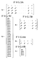
- The invention will be described in the following with reference to the drawings. In the drawings:
- Figs. 1 and 2 are schematic diagrams which are used for describing the constructions of the digital information data recorded on a compact disc in accordance with an embodiment of the present invention;
- Figs. 3A, 3B, 4A, and 4B are schematic diagrams which are used for describing the secondary or subchannel signals of a compact disc;
- Figs. 5A-5C, 6A, and 6B show the parity check matrices and the reproduction data matrices of the error correction code in an embodiment of the present invention;
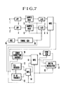
- Fig. 7 is a block diagram showing the circuitry construction of the recording system of an embodiment of the present invention;
- Fig 8 is a block diagram showing the circuitry construction of the reproducing system of an embodiment of the present invention;
- Fig. 9 is a block diagram showing the construction of the error correction encoder in an embodiment of the present invention;
- Figs. 10-12 are schematic diagrams which are used for describing the interleave-processing by the error correction encoder according to the present invention;
- Fig. 13 is a block diagram showing the construction by the error correction decoder in an embodiment of the present invention; and
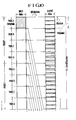
- Figs. 14 and 15 are schematic diagrams which are used for describing the interleave-processing in other embodiments by the error correction encoder according to the present invention.
- The data construction of the signal to be recorded on a compact disc will be described with reference to Figs. 1 and 2.
- Fig. 1 shows the data stream recorded on a compact disc. One FRAME consists of 588 bits of record data, and each FRAME has at its head a 24- bit frame sync pulse FS of a specific bit pattern. The frame sync pulse FS is followed by DC-restriction bits RB (3 bits), which are used to suppress the DC components of the digital data to be transmitted. Thereafter, the 32 combinations consisting of the Oth - 32nd data bits DBs each having 14 bits and the 3-bit DC-restriction bits RB, alternately, are further recorded. The Oth bits among these data bits DBs are called a secondary or subchannel signal or user's bits, and used to control the playback of a disc and to display the relating information or the like. The 1 st - 12th and 17th - 28th data bits DBs are assigned for audio data in the primary or main channel. The remaining 13th - 16th and 29th - 32nd data bits DBs are assigned for check data of the error correction code in the primary or main channel. Each of the data bits DBs consists of 14 bits into which the 8-bit data has been converted by the 8 - 14 conversion upon recording.
- One BLOCK consists of the above-mentioned 98 FRAMEs of digital signals, and various processings can be performed on the basis of such a BLOCK unit.
- Fig. 2 shows the data constructional state of one BLOCK (98 FRAMEs) in that 98 FRAMEs are arranged sequentially in parallel, wherein each of the data bits DBs is represented by 8 bits and the respective DC-restriction bits are excluded for simplicity of the figure. The subcoding signals P-W in the Oth and 1st FRAMEs form the sync patterns which are predetermined bit patterns. For the Q channel, the CRC codes for error detection are inserted in the latter 16 FRAMEs among the 98 FRAMEs.
- The P-channel signal may be a flag to indicate a music program and a pause in that program. In a specific embodiment, the P-channel signal may be a two-level signal having a relatively lower level throughout the duration of a music program and a relatively higher level throughout the duration of a pause within or between such programs. In addition, the P-channel signal may appear as an alternating signal having a frequency on the order of about 2 Hz to define the lead-out section of the record disc. It will be appreciated, therefore, that detection and counting of this 2 Hz signal in the P channel are indicative of the lead-out section of the disc so as to suitably select and play back the designated music programs. The Q channel enables the more complicated control of this type. For example, when the Q-channel information is stored in a microcomputer equipped in the record disc playback device, it is possible to shift quickly from one music program to another and, moreover, from one portion of a program to yet another portion of a still further program during the playback of a music program; thus, respective ones of the recorded music programs may be selected at random by detecting and processing the above-mentioned Q-channel information. The other R through W channels can be used to indicate or explain by audible voice an author, composer, performers, explanation, poetry, title or the like of the music programs recorded on the record disc.
- One PACKET consists of the 96-FRAME data excluding the sync pattern and P and Q channels among one BLOCK. As shown in Fig. 3A, this PACKET of (6x96) bits is further divided into four PACKs of A, B, C, and D, each having 24 SYMBOLs. The first SYMBOL of each PACK is a COMMAND and the subsequent 19 SYMBOLs are data, and the remaining 4 SYMBOLs are check data of the error correction code of each PACK. This COMMAND has six bits consisting of the 3-bit MODE and the 3-bit ITEM as shown in Fig. 3B.
- The four 3-bit MODEs are defined:
- (0 0 0) : the ZERO-mode
- (0 0 1) : the GRAPHIC-mode
- (0 1 0) : the STILL-PICTURE-mode
- (0 1 1) : the SOUND-mode
- The three bits of the ITEM represent the information of the more detailed operational mode in each of the aforementioned operational modes. The ZERO-mode represents the case where no information is recorded in the R to W channels of the secondary or subchannel signals. In this ZERO-mode, as shown in Fig. 4A, all bits in the PACK including the six bits of MODE and ITEM are zero.
- In the GRAPHIC-mode where the three bits of MODE are (0 0 1), as shown in Fig. 4B, the data in each PACK is arranged. When executing the GRAPHIC operation of the font such as characters, sentences, or the like with this GRAPHIC-mode, three bits of ITEM become (0 0 1 in the case of full-GRAPHIC to control the data in the entire display areas of the display device, three bits of ITEM become (0 1 0). The second SYMBOL in each PACK in this GRAPHIC-mode is INSTRUCTION. This INSTRUCTION gives an instruction necessary for control in the operational mode specified by a COMMAND consisting of MODE and ITEM.
- The error correction coding processing is performed to the two SYMBOLs of COMMAND and INSTRUCTION in this GRAPHIC-mode, and the resultant 2-SYMBOL check data is added. The 16 SYMBOLs in the PACK are used as a data area. The error correction coding processing is performed to the total 20 SYMBOLs in the PACK, and the resultant 4-SYMBOL check data is added.
- Even in the STILL-PICTURE-mode or SOUND-mode, when predetermined COMMAND and INSTRUCTION are used, the error correction coding processing is also performed in the same way as above.
- A (24, 20) REED-SOLOMON code is used as an error correction code for the PACK of (6x24) bits. This REED-SOLOMON code is expressed by a polynomial,

-

- One PACK of the reproduction data is expressed by the reproduction data matrix Vp as shown in Fig. 5C. Each suffix added to the respective 24 SYMBOLs indicates the SYMBOL number of the secondary or subchannel signals, and a character n in this suffix represents a PACK No. S24n is a COMMAND, S24n+1 is an INSTRUCTION, Q24n+2 and Q24n+3 are check data SYMBOLs for this COMMAND and INSTRUCTION, and P24n+20, P24n+21, P24n+22, and P24n+23 are check data SYMBOLs of such PACKs as described above. The check data of these four SYMBOLs satisfies (Hp. Vp = 0).
- The (4, 2) REED-SOLOMON code is used as an error correction code for COMMAND and INSTRUCTION. This REED-SOLOMON code is expressed by a polynomial,


- The REED-SOLOMON code including four P-check-data SYMBOLs can correct 1-SYMBOL error and 2-SYMBOL error and detect 3-or-more-SYMBOL errors. The REED-SOLOMON code including two Q SYMBOLs can correct 1-SYMBOL error and detect 2-or-more-SYMBOL errors.
- Fig. 7 shows the block diagram of the fundamental circuitry construction of the recording system to produce the data to be recorded on a compact disc. In Fig. 7,
reference numerals pass filters circuits D converters multiplexer 9 and supplied to anerror correction encoder 10. - The
error correction encoder 10 cross-interleaves the audio PCM signal to code for allowing the error correction to be performed by the REED-SOLOMON code. The cross-interleave-processing serves to rearrange the data sequence so that each SYMBOL is contained in the two different error correction code series. The output of thiserror correction encoder 10 is supplied to amultiplexer 11. - There are further provided an
encoder 12 with respect to the P and Q channels of the secondary or subchannel signals and anencoder 13 with respect to the R through W channels, and their respective outputs are synthesized by amultiplexer 14 and supplied to themultiplexer 11. The output of themultiplexer 11 is supplied to adigital modulator 15, where it is modulated from 8 bits to 14 bits. Frame syncs from async signal generator 16 are added to thedigital modulator 15 and output from anoutput terminal 17. Theencoder 12 for the P and Q channels has such a construction that it adds a 16-bit CRC code to the Q-channel data. Theencoder 13 for the R - W channels performs the error correction coding using the REED-SOLOMON code and the interleave-processing. - Clock pulses and timing signals formed by a
timing generator 18 are supplied to each circuit of thesample holding circuits D converters multiplexers reference numeral 19 indicates an oscillator for generating master clocks. - Fig. 8 shows the block diagram of the circuitry construction of the reproducing system to process the reproduction signals of a compact disc. In Fig. 8, the signal reproduced optically from a compact disc is supplied to an input terminal indicated by a
reference numeral 20. - This reproduction signal is supplied through a
waveform shaping circuit 21 to adigital demodulator 22,clock recovery circuit 23, and async detection circuit 24. The bit clock which is synchronized with the reproduction data is taken out by theclock recovery circuit 23 having the PLL construction. Thesync detection circuit 24 detects the frame sync and generates the timing signals synchronized with the reproduction data, and supplies predetermined timing signals to each circuit of the reproducing system. - The data in the main channel among the outputs of the
digital demodulator 22 is subject to the processings for error detection, error correction, and interpolation by anerror correction circuit 25. The secondary or subchannel signals are subject to the processings for error detection and error correction by adecoder 33. - The output of the
error correction circuit 25 is supplied to ademultiplexer 26 to be divided into two channels. The respective outputs in each channel pass through a D/A converter 27 and a low-pass filter 29, and a D/A converter 28 and a low-pass filter 30. The reproduction audio signals in each channel appear atoutput terminals - The data in the P and Q channels of the secondary or subchannel signals obtained from the
decoder 33 is supplied to asystem controller 34 comprising a microcomputer. This data is used to execute the rapid access operation for reproducing the beginnings of music programs, random selecting operation, or other operations. The time code included in the Q channel is supplied to aline display 35 for indication on the display. - The picture display data included in the R - W channels is converted into analog data by a D/
A converter 36, then taken out at anoutput terminal 38 through a low-pass filter 37. This display signal is supplied to a CRT display. Furthermore, the audio data such as explanations of music programs which are included in the R through W channels is taken out at an output terminal 41 through a D/A converter 39 and a low-pass filter 40, then supplied through a low-frequency amplifier to a speaker (not shown). - The
encoder 13 concerning the R - W channels is provided with an error correction encoder shown in Fig. 9. - The error correction encoder consists of, as shown by the broken lines, a Q-check-
data generator 51 of the previously mentioned (4, 2) REED-SOLOMON code, a P-check-data generator 52 of the aforementioned (24, 20) REED-SOLOMON code, and aninterleaving circuit 53. The total 18 SYMBOLs of S24n,S24n+ 1, and S24n+4 through S24n+ig in the nth PACK are input to this error correction encoder. - The two SYMBOLs S24nand S24n+ are supplied to the Q-check-
data generator 51 to generate the two check data SYMBOLs of Q24n+2 and Q24n+3. The 20 SYMBOLs including this Q check data are input to the P-check-data generator 52 to generate the four check data SYMBOLs. The 24 SYMBOLs to be output from this P-check-data generator 52 are supplied to theinterleaving circuit 53. - The
interleaving circuit 53 is constructed by an RAM and its address controller and generates the output data of which a predetermined delay time value has been added to each SYMBOL of the input data by controlling the write addresses and the read addresses. As shown in Fig. 9, means for adding the predetermined delay time value to each SYMBOL is represented as a plurality of delay elements for simplicity of understanding. The following delay elements are used: - Delay
elements - Delay
elements - Delay
elements - Delay
elements - Delay
elements - Delay
elements - Delay
elements - The delay time value of the SYMBOL in which no delay element is inserted is set to 0. As described above, the three combinations consisting of the eight kinds of delay time values of 0 to 7 PACKs are provided.
- This
interleaving circuit 53 performs such an interleave-processing as shown in Fig. 10. In Fig. 10, there are shown in parallel the eight sequential PACKs in the input data series and the output data series having the same length as the input data series. Referring to the first PACK A (shown by the area indicated by the oblique lines) in the input data series, the 24 SYMBOLs in this PACK A are interleaved into the locations which are apart by only a distance of 8 or 9 SYMBOLs in the output data series. If the output data series are divided into equal intervals each consisting of 8 SYMBOLs, the 3 SYMBOLs in the PACK A are arranged as the head SYMBOL into each of the first to third 8-SYMBOL groups in the output data series. The next three SYMBOLs in the above-mentioned PACK A are arranged as the second SYMBOL into each of the 4th to 6th 8-SYMBOL groups. - In the same manner as above, the respective 3 SYMBOLs in the PACK A are arranged into the locations where each SYMBOL is shifted for every three 8-SYMBOL groups. Consequently, the 3 SYMBOLs in the PACK A are arranged as the 8th SYMBOL of each group into the final three 8-SYMBOL groups in the output data series shown in Fig. 10. Among 24 SYMBOLs consisting of these three 8-SYMBOL groups, the SYMBOLs in the above-mentioned PACK A are arranged with the distance of each eight SYMBOLs. In the boundary between the three 8-SYMBOL groups and the next three 8-SYMBOL groups, the distance of nine SYMBOLs exists since one SYMBOL is shifted.
- The SYMBOLs in a plurality of PACKs with the timings which are later than the PACK A are arranged by being interleaved in the same manner as the PACK A into the locations before the locations where the SYMBOLs in the PACK A have been arranged among the 8-SYMBOL groups. Furthermore, the SYMBOLs in a plurality of PACKs with the timing periods before the PACK A are arranged by being interleaved similarly to the PACK A into the locations after the locations where the SYMBOLs in the PACK A have been arranged among the 8-SYMBOL groups.
- According to the actual measurement of the error states in the secondary or subchannel signals reproduced from a compact disc, the burst errors of four or more SYMBOLs were hardly detected. Therefore, by dispersedly recording (namely, by interleaving) the 24 SYMBOLs included in the same series of the (24, 20) REED-SOLOMON code in such a manner as described above, it is possible to effectively prevent that the error correction becomes impossible due to the occurrence of 2-or-more-SYMBOL errors.
- Returning to Fig 9, the
interleaving circuit 53 serves to interleave so that the distances between the COMMANDS, INSTRUCTIONs, and SYMBOLs of these Q check data which are included in the same PACK become larger than those of the other SYMBOls. For this purpose, as shown in Fig. 9, theinterleaving circuit 53 includes the six oblique supplying lines, in other words, all of the supplying lines of the input SYMBOLs for each delay element are not parallel. - According to an embodiment of the present invention, the construction shown in Fig. 9 is changed so that all of the supplying lines of the input SYMBOLs are parallel. Fig. 11 shows the relationship between the 24 SYMBOLs in one PACK and the locations of the data in the output series after interleaving in such a case. In Fig. 11 and Fig. 12, which will be described later, the time width of one PACK of the input data is increased by eight times the inherent time width.
- As shown in Fig. 11, the delay time values of 0, 1, 2, 3, ... 7 PACKs are respectively given to the first eight SYMBOLs S24n, S24n+1, Q24n+2, Q24n+3, ... S24n+7 of the input SYMBOLs. Hence, these eight SYMBOLs change to the SYMBOLs whose SYMBOL numbers are (-24), (-24 x 2), (-24 x 3), ... (-24 x 7) in the output data series. The delay time values of 0, 1, ... 7 PACKs are also given to the next eight SYMBOls S24n+8, ... S24n+15 of the input SYMBOLs, respectively. Furthermore, the same delay time values are also given to the next eight SYMBOLs S24n+16, ... S24n+23, respectively. As a result of such an interleave-processing, the mutual distances of the first four SYMBOLs in the PACK become equally 24 SYMBOLs.
- In another embodiment of the present invention, as shown in Fig. 9, the
interleaving circuit 53 is used so that the SYMBOL S24n+l is supplied to thedelay element 82, the SYMBOL S24n+18 is supplied to thedelay element 61; similarly, the SYMBOL Q24n+2 to thedelay element 65, the SYMBOL S24n+5 to thedelay element 62, the SYMBOL Q24n+3 to thedelay element 87, and the SYMBOL P24n+23 to thedelay element 63. Therefore, a pair of mutual locations of the above-mentioned SYMBOLs are exchanged, so that the relationship between the input data series and the data series after interleaving is as shown in Fig. 12. As will be obvious from Fig. 12, the mutual distances of the first four SYMBOLs in the PACK are as shown below. - The distance between S24n and S24n=1 : 65 SYMBOLs
- The distance between SZqn+1 and Q24n+2 : 58 SYMBOLs
- The distance between Q24n+2 and Q24n+3 65 SYMBOLs
- As described above, it is possible to increase the mutual distances of the four SYMBOLs by two or more times as compared with the 25 SYMBOLs, and to elevate the error correcting ability for the burst errors which may occur in the reproduction data.
- As described above, it is desirable to set the distances between the SYMBOLs of the control data after interleave-processing so as to be maximum; however, there is also an exceptional case where it is not always necessary to set the maximum distance in consideration of the length of the burst errors which could be caused in the transmission line to be used.
- Fig. 13 shows an error correction decoder with respect to the R through W channels provided in the
decoder 33 for the subchannel or secondary signals of the reproducing system. - This error correction decoder comprises, as shown by the broken lines, a
de-interleaving circuit 91 to which the 24 SYMBOLs in one PACK of the reproduced secondary or subchannel signals are supplied, a P-decoder 92 of the (24, 20) REED-SOLOMON code to which the output of thisde-interleaving circuit 91 is supplied, and a Q-decoder 93 of the (4, 2) REED-SOLOMON code to which the four SYMBOLs to be output from this P-decoder 92 are supplied. - On the contrary to Fig. 13, the Q-
decoder 93 may be provided at the front stage of the P-decoder 92. It may be also possible to generate the flag code indicating the contents (i.e., no error, the correction of 1-SYMBOL error, correction of 2-SYMBOL error, and detection of 3-or-more-SYMBOL errors) of the error detection and error correction which have been executed by the P-decoder 92 (or Q-decoder 93) and to utilize this flag code for the error correction processing in the Q-decoder 93 (or P-decoder 92). - The input data to the
de-interleaving circuit 91 corresponds to the output data from theinterleaving circuit 53 in Fig. 9. The deinterleave-processing is performed so that the delay time values given by thisinterleaving circuit 53 are cancelled and each SYMBOL has evenly the delay time values of seven PACKs. Actually, this de-interleaving is performed by controlling the write addresses and read addresses in the RAM. As shown in Fig. 13, thede-interleaving circuit 91 is constructed such that the delay elements having predetermined delay time values are arranged in the transmission lines of each SYMBOL. The delay elements of seven PACKs are inserted into the transmission lines of the SYMBOLs having the delay time value of 0 in theinterleaving circuit 53, respectively. The delay elements of 6, 5, 4, 3, 2, and 1 PACKs are inserted respectively into the transmission lines of the SYMBOLs having the delay time values of 1, 2, 3, 4, 5, and 6 PACKs in theinterleaving circuit 53. No delay element is inserted into the transmission line of the SYMBOL having the delay time value of seven PACKs in theinterleaving circuit 53. - The P-
decoder 92 has a syndrome generator to generate four syndromes by calculation of (Hp• Vp). If there is no error, these four syndromes are all zero. Checking these four syndromes enables the detections of a 1-SYMBOL error, 2-SYMBOL error, and 3-or-more-SYMBOL errors, and obtaining the error locations of the 1-SYMBOL error and 2-SYMBOL error enables the corrections or these errors. - The Q-
decoder 93 has a syndrome generator to generate two syndromes by calculation of (Hq·Vq). By utilizing these two syndromes, it is possible to correct a 1-SYMBOL error and to detect 2-or-more-SYMBOL errors. - It may be possible to use a complete-type interleave-processing in that the SYMBOLs in a plurality of PACKs are written in the RAM and the above-mentioned SYMBOLs in a plurality of PACKs are read from the RAM using the read addresses in a sequence different from a change in these write addresses.
- As shown in an enlarged schematic diagrams of Fig. 14, for example, the PACK A includes the twenty information SYMBOLs of SOA, S1A, ... S19A and the four check codes of POA, P1A, P2A, and P3A. When recording on a disc, these SYMBOLs in the four PACKs A, B, C, and D are interleaved.
- In the example shown in Fig. 14, all of the 20 SYMBOLs in one PACK are used as the data and the two P and Q check data as described above are not used. However, this difference will not cause the essential difference between the constructions of the error correction encoder and the error correction decoder. Namely, the encoder and decoder are constituted so that they can correspond to the two check codes similarly to those shown in Figs. 9 and 13, and that it is appropriately selected by the control data (e.g., INSTRUCTION) that whether the Q-check-data generator and the Q-decoder are made operative or not.
- The interleave-processing shown in Fig. 14 is performed as follows. That is to say, the recording areas for the 96 SYMBOLs divided by the syncs of the secondary or subchannel signals are divided into 24 areas each having four SYMBOLs. The SYMBOL taken out of the PACK A is arranged as the first SYMBOL. The SYMBOL taken out of the PACK B is arranged as the second SYMBOL. The SYMBOL taken out of the PACK C is arranged as the third SYMBOL. And the SYMBOL taken out of the PACK D is arranged as the fourth SYMBOL. By performing such an interleave-processing, it is possible to diminish the occurrence of 3-or-more-word errors due to the burst error.
- Furthermore, as shown in Fig 14, the ten information SYMBOLs bearing even numbers among the 20 information SYMBOLs included in each PACK are recorded into the sections for the former 40 SYMBOLs. The ten information SYMBOLs bearing odd numbers are recorded into the sections of the latter 40 SYMBOLs. The parity SYMBOLs are recorded into the sections for the 16 SYMBOLs locating intermediately in the order of (Po - P2 - P1 - P3). As described above, since the information SYMBOLs bearing even and odd numbers are recorded in the locations which are as far as possible, it is possible to elevate the interpolating ability when the error correction is impossible.
- In another embodiment of the present invention, the buffer required to decode is (96 x 6 bits = 576 bits), the restricted length (in each PACK) of the code is 93 SYMBOLs, and the length which can be interpolated is 52 SYMBOLs.
- Fig. 15 shows the error detection and correction codings of the secondary or subchannel signals in still another embodiment of the present invention.
- In the same manner as Fig. 14 described above, the recording areas for the 96 SYMBOLs are divided into four areas, and the SYMBOL series in the PACK A is recorded in the inherent recording areas for the 96 SYMBOLs as shown by the oblique lines in Fig. 15. The six SYMBOLs among the SYMBOLs in this PACK A are recorded in the first locations in the sections divided so as to have four SYMBOLs respectively. In the same way as above, each group consisting of the six SYMBOLs is recorded into the second, third, and fourth locations, respectively.
- The SYMBOL series in the PACK B is recorded between the locations from the second position among the four areas thus divided to the second position among the recording areas of the next 96 SYMBOLs. The SYMBOL series in the PACK C is recorded between the locations from the third position to the third position among the next recording areas. The SYMBOL series in the PACK D is recorded between the locations from the fourth position to the fourth position among the next recording areas.
- The interleave-processing for the SYMBOL series in these PACKs B, C and D is the same as PACK A.
- As described above, the buffer of (104 x 6 bits = 624 bits) is required to decode in the specific embodiment of the present invention in this case where the secondary or subchannel signals are recorded over other recording areas. The restricted lengths of the codes are 96 SYMBOLs in the case of PACK A, and 98 SYMBOLs (because the sync pattern is included) in the cases of PACKs B, C and D. Therefore, the interpolated length, for example, the length when the SYMBOL S2A is interpolated by a mean value of the SYMBOLs SlA and S3A becomes 58 SYMBOLs.
- In the above description, the same error correction coding and error correction decoding processings are performed for the 96 SYMBOLs (PACKs A - D) of the secondary or subchannel signals. However, different processings may be performed for each PACK in accordance with the contents of information of the secondary or subchannel signals. The first SYMBOL (in Fig. 2, the second data FRAME) among the 96 SYMBOLs is used as a header indicating the contents of information in each PACK and a difference between the error correction processings as described above. This header is included in the PACK A.
- Therefore, in the case of picture information in which errors are inconspicuous, it may be possible to perform the error correction processing for only the PACK A which includes a header and to perform the interpolation processing for other PACKs.
- Furthermore, the present invention is not limited to the data to be recorded on a compact disc, but it may be applied to the data to be recorded on other record media such as a magnetic tape or the like and to the error correction coding of the transmission data of the videotex system.
- Any codes other than the REED-SOLOMON code may be used as an error correction code. It is also possible to use an error detection code such as a CRC code as one of the two kinds of data and to use an error correction code as the other one. An error correction code of the bit unit such as a BCH code may be used instead of an error correction code of the SYMBOL unit.
- According to the present invention, different from the error detection by CRC, it is possible to realize the error correcting method which can provide the high correcting ability by combining the interleave-processing and the error correction coding processing in each dividing unit without requiring any complicated circuit and any large buffer memory such as the error correction code for the data in the primary or main channel. Moreover, according to the present invention, it is possible to perform the different error detection and correction on the dividing unit basis due to a difference in the picture information and the audio information since the error detection and correction processings are performed on the dividing unit basis. Furthermore, since the data rate of the secondary or subchannel signals to be reproduced from a compact disc is relatively slow, the error correction processing can be performed using a microcomputer, resulting in the simple and low-priced construction.
- According to the invention, if there are two kinds of data as the transmission data, it is possible to code one of them so that it has the error correcting ability which is more effective than that of the other one.
- In an example of the secondary or subchannel signals of a compact disc, the dual error correction coding processings of the (24, 20) REED-SOLOMON code and the independent (4, 2) REED-SOLOMON code are performed to the four SYMBOLs having the information concerning the operational mode and the contents of controls. The interleave-processing is performed for these four SYMBOLs so that they are interleaved mutually as far as possible as compared with the distances between other SYMBOLs.
- These dual processings cause the error correcting ability for the four SYMBOLs to be elevated. Moreover, it will be easily understood that such processings will not affect the error correction coding at all which is performed on the PACK unit basis so as to reduce its error correcting ability.
Claims (20)
error correction to each of said PACKs,
subchannel data for transmission together with frame synchronizing signals (FS).
characterized by
redundant code added to each of the PACKs, thereby reproducing said grouped secondary data or subchannel data, and
data.
Priority Applications (1)
| Application Number | Priority Date | Filing Date | Title |
|---|---|---|---|
| AT83104173T ATE94679T1 (en) | 1982-04-28 | 1983-04-28 | PROCEDURE, ARRANGEMENT AND RECORDING MEDIA FOR ERROR CORRECTION. |
Applications Claiming Priority (4)
| Application Number | Priority Date | Filing Date | Title |
|---|---|---|---|
| JP7222082A JPS58188315A (en) | 1982-04-28 | 1982-04-28 | Disc reproducer |
| JP72220/82 | 1982-04-28 | ||
| JP25815/83 | 1983-02-18 | ||
| JP58025815A JPH0767088B2 (en) | 1983-02-18 | 1983-02-18 | Error correction coding method |
Publications (3)
| Publication Number | Publication Date |
|---|---|
| EP0093969A2 EP0093969A2 (en) | 1983-11-16 |
| EP0093969A3 EP0093969A3 (en) | 1987-01-07 |
| EP0093969B1 true EP0093969B1 (en) | 1993-09-15 |
Family
ID=26363507
Family Applications (1)
| Application Number | Title | Priority Date | Filing Date |
|---|---|---|---|
| EP83104173A Expired - Lifetime EP0093969B1 (en) | 1982-04-28 | 1983-04-28 | Method, apparatus and recording medium for error correction |
Country Status (10)
| Country | Link |
|---|---|
| US (1) | US4541093A (en) |
| EP (1) | EP0093969B1 (en) |
| KR (1) | KR920000164B1 (en) |
| AU (2) | AU562742B2 (en) |
| BR (1) | BR8302210A (en) |
| CA (1) | CA1196106A (en) |
| DE (1) | DE3382713T2 (en) |
| DK (1) | DK172468B1 (en) |
| ES (2) | ES521876A0 (en) |
| HK (1) | HK120795A (en) |
Cited By (1)
| Publication number | Priority date | Publication date | Assignee | Title |
|---|---|---|---|---|
| CN106708652A (en) * | 2016-12-29 | 2017-05-24 | 清华大学 | No-parity controller and parity server serial port communication method |
Families Citing this family (42)
| Publication number | Priority date | Publication date | Assignee | Title |
|---|---|---|---|---|
| US4949326A (en) * | 1986-12-10 | 1990-08-14 | Matsushita Electric Industrial Co., Ltd. | Optical information recording and reproducing system using optical disks having an error correction function |
| JP2533076B2 (en) * | 1983-04-30 | 1996-09-11 | ソニー株式会社 | Encoding method for error correction |
| JPS59207413A (en) * | 1983-05-11 | 1984-11-24 | Sony Corp | Information recording method |
| JPH0661156B2 (en) * | 1983-05-21 | 1994-08-10 | ソニー株式会社 | Encoding method for error correction |
| JPS6029073A (en) * | 1983-06-17 | 1985-02-14 | Hitachi Ltd | Digital signal configuration system |
| US4677622A (en) * | 1983-06-22 | 1987-06-30 | Hitachi, Ltd. | Error correction method and system |
| JPS6052960A (en) * | 1983-09-01 | 1985-03-26 | Sony Corp | Disk reproducer |
| JPH0634304B2 (en) * | 1983-09-01 | 1994-05-02 | ソニー株式会社 | Disk playback device |
| JPH0787021B2 (en) * | 1983-10-14 | 1995-09-20 | ヤマハ株式会社 | Subcode signal reading circuit |
| DE3485541D1 (en) * | 1983-12-16 | 1992-04-09 | Sony Corp | DEVICE FOR DISK PLAYBACK. |
| JPS60185263A (en) * | 1984-03-02 | 1985-09-20 | Hitachi Ltd | Error correcting system |
| DE3575646D1 (en) * | 1984-03-24 | 1990-03-01 | Philips Nv | METHOD FOR TRANSMITTING INFORMATION WITH ERROR CORRECTION FOR DATA WORDS, AN ERROR CORRECTION DECODING METHOD FOR SUCH DATA WORDS, AN ARRANGEMENT FOR INFORMATION TRANSFER FOR USE WITH THE METHOD, AND A METHOD FOR USING AN APPARATUS. |
| JPH07111815B2 (en) * | 1984-07-23 | 1995-11-29 | 株式会社日立製作所 | Digital signal recording system |
| US4661955A (en) * | 1985-01-18 | 1987-04-28 | Ibm Corporation | Extended error correction for package error correction codes |
| JPS62120670A (en) * | 1985-11-20 | 1987-06-01 | Sony Corp | Method for correcting error of data |
| NL192151C (en) * | 1986-02-24 | 1997-02-04 | Philips Electronics Nv | Method and device for storing and reading digitally encoded information, optionally protected or not by an error-correcting code. |
| GB2187364B (en) * | 1986-02-26 | 1989-10-25 | Sony Corp | Methods of and apparatus for coding digital data |
| JP2637401B2 (en) * | 1986-06-26 | 1997-08-06 | キヤノン株式会社 | Recording device |
| JPS6333028A (en) * | 1986-07-26 | 1988-02-12 | Nec Corp | Signal detection system |
| JPH0690853B2 (en) * | 1986-12-23 | 1994-11-14 | ソニー株式会社 | Digital signal time base corrector |
| US4864572A (en) * | 1987-05-26 | 1989-09-05 | Rechen James B | Framing bitstreams |
| US4998252A (en) * | 1987-08-06 | 1991-03-05 | Sony Corporation | Method and apparatus for transmitting digital data |
| JPH0193933A (en) * | 1987-10-06 | 1989-04-12 | Sony Corp | Error correction encoder |
| US4932018A (en) * | 1987-11-19 | 1990-06-05 | Sanyo Electric Co., Ltd. | Integrated circuit for generating indexing data in a CD player |
| CZ284768B6 (en) * | 1988-01-19 | 1999-02-17 | Philips Electronics N. V. | Method of transmission information signals and apparatus for making the same |
| JPH0722367B2 (en) * | 1988-01-29 | 1995-03-08 | パイオニア株式会社 | Image data recording / playback method |
| JP2811445B2 (en) * | 1988-03-22 | 1998-10-15 | パイオニア株式会社 | Recording method and reproduction method of image information |
| JPH01256061A (en) * | 1988-04-04 | 1989-10-12 | Pioneer Electron Corp | Information recording and reproducing system |
| US4942551A (en) * | 1988-06-24 | 1990-07-17 | Wnm Ventures Inc. | Method and apparatus for storing MIDI information in subcode packs |
| WO1991019293A1 (en) * | 1990-05-21 | 1991-12-12 | Ted Hugh Wilburn | Musicsee/lyricsee |
| NL9100285A (en) * | 1991-02-19 | 1992-09-16 | Koninkl Philips Electronics Nv | TRANSMISSION SYSTEM, AND RECEIVER FOR USE IN THE TRANSMISSION SYSTEM. |
| JP2970008B2 (en) * | 1991-02-22 | 1999-11-02 | ソニー株式会社 | Disk-shaped recording medium playback device |
| KR100272118B1 (en) * | 1991-11-06 | 2000-11-15 | 이데이 노부유끼 | Optical disk player and tracking servo circuit with digital servo control circuit |
| GB9213272D0 (en) | 1992-06-23 | 1992-08-05 | Digital Equipment Int | Check sequence preservation |
| JP3170920B2 (en) * | 1992-12-25 | 2001-05-28 | ソニー株式会社 | Error correction method and correction circuit |
| EP0671738B1 (en) * | 1993-09-29 | 2001-07-11 | Sony Corporation | Method and device for reproducing data |
| CN1147854C (en) | 1994-02-28 | 2004-04-28 | 索尼公司 | Method and device for recording data, data recording medium, and method and device for reproducing data |
| US6079041A (en) * | 1995-08-04 | 2000-06-20 | Sanyo Electric Co., Ltd. | Digital modulation circuit and digital demodulation circuit |
| DE19535358C1 (en) * | 1995-09-22 | 1997-03-06 | Siemens Ag | Utility data processing method for telecommunication system |
| DE59606260D1 (en) * | 1995-09-22 | 2001-02-01 | Siemens Ag | METHOD AND CIRCUIT ARRANGEMENT FOR PROCESSING USER DATA |
| US6334024B1 (en) | 1996-02-13 | 2001-12-25 | Victor Company Of Japan, Ltd. | Helical scan data recording apparatus and a helical scan data reproducing apparatus |
| GB2390785B (en) * | 2002-07-12 | 2005-10-19 | Nokia Corp | Information service broadcasting or multicasting |
Family Cites Families (10)
| Publication number | Priority date | Publication date | Assignee | Title |
|---|---|---|---|---|
| JPS5380105A (en) * | 1976-12-24 | 1978-07-15 | Sony Corp | Digital signal transmission method |
| US4281355A (en) * | 1978-02-01 | 1981-07-28 | Matsushita Electric Industrial Co., Ltd. | Digital audio signal recorder |
| US4211997A (en) * | 1978-11-03 | 1980-07-08 | Ampex Corporation | Method and apparatus employing an improved format for recording and reproducing digital audio |
| JPS5758210A (en) * | 1980-09-26 | 1982-04-07 | Hitachi Ltd | Error correction range controlling circuit |
| US4467373A (en) * | 1980-10-09 | 1984-08-21 | Micro Consultants Limited | Storage and retrieval of digital data on video tape recorders |
| US4380071A (en) * | 1981-02-02 | 1983-04-12 | Sony Corporation | Method and apparatus for preventing errors in PCM signal processing apparatus |
| US4455635A (en) * | 1981-10-14 | 1984-06-19 | Rca Corporation | Coding system for recorded digital audio |
| DE3575646D1 (en) * | 1984-03-24 | 1990-03-01 | Philips Nv | METHOD FOR TRANSMITTING INFORMATION WITH ERROR CORRECTION FOR DATA WORDS, AN ERROR CORRECTION DECODING METHOD FOR SUCH DATA WORDS, AN ARRANGEMENT FOR INFORMATION TRANSFER FOR USE WITH THE METHOD, AND A METHOD FOR USING AN APPARATUS. |
| CA1265250A (en) * | 1985-03-04 | 1990-01-30 | Alan Douglas Clark | Data transmission |
| DE3685991T2 (en) * | 1985-05-21 | 1993-03-04 | Sony Corp | ARRANGEMENT FOR DECODING AN ERROR CORRECTING CODE. |
-
1983
- 1983-04-22 CA CA000426562A patent/CA1196106A/en not_active Expired
- 1983-04-25 US US06/488,373 patent/US4541093A/en not_active Expired - Lifetime
- 1983-04-27 AU AU13976/83A patent/AU562742B2/en not_active Expired
- 1983-04-27 KR KR1019830001780A patent/KR920000164B1/en not_active IP Right Cessation
- 1983-04-27 DK DK198301876A patent/DK172468B1/en not_active IP Right Cessation
- 1983-04-27 ES ES521876A patent/ES521876A0/en active Granted
- 1983-04-28 DE DE83104173T patent/DE3382713T2/en not_active Expired - Lifetime
- 1983-04-28 EP EP83104173A patent/EP0093969B1/en not_active Expired - Lifetime
- 1983-04-28 BR BR8302210A patent/BR8302210A/en not_active IP Right Cessation
-
1984
- 1984-05-24 ES ES532760A patent/ES532760A0/en active Granted
-
1987
- 1987-08-27 AU AU77652/87A patent/AU610078B2/en not_active Expired
-
1995
- 1995-07-20 HK HK120795A patent/HK120795A/en not_active IP Right Cessation
Cited By (2)
| Publication number | Priority date | Publication date | Assignee | Title |
|---|---|---|---|---|
| CN106708652A (en) * | 2016-12-29 | 2017-05-24 | 清华大学 | No-parity controller and parity server serial port communication method |
| CN106708652B (en) * | 2016-12-29 | 2019-01-04 | 清华大学 | No parity controller and the serial port communication method for having even-odd check servomechanism |
Also Published As
| Publication number | Publication date |
|---|---|
| AU610078B2 (en) | 1991-05-16 |
| BR8302210A (en) | 1984-01-03 |
| DE3382713T2 (en) | 1994-01-13 |
| DK172468B1 (en) | 1998-09-07 |
| AU562742B2 (en) | 1987-06-18 |
| DE3382713D1 (en) | 1993-10-21 |
| DK187683D0 (en) | 1983-04-27 |
| KR840004840A (en) | 1984-10-24 |
| EP0093969A3 (en) | 1987-01-07 |
| EP0093969A2 (en) | 1983-11-16 |
| AU7765287A (en) | 1987-12-03 |
| US4541093A (en) | 1985-09-10 |
| ES8507749A1 (en) | 1985-09-01 |
| AU1397683A (en) | 1983-11-03 |
| CA1196106A (en) | 1985-10-29 |
| HK120795A (en) | 1995-07-28 |
| ES8407276A1 (en) | 1984-09-01 |
| KR920000164B1 (en) | 1992-01-09 |
| ES521876A0 (en) | 1984-09-01 |
| DK187683A (en) | 1983-10-29 |
| ES532760A0 (en) | 1985-09-01 |
Similar Documents
| Publication | Publication Date | Title |
|---|---|---|
| EP0093969B1 (en) | Method, apparatus and recording medium for error correction | |
| EP0137855B1 (en) | Data transfer system using digital disc | |
| SU1505451A3 (en) | Device for decoding information with error correction | |
| EP0127687B1 (en) | Method of recording pcm signal | |
| KR920008229B1 (en) | Digital data signal recording method | |
| US4630272A (en) | Encoding method for error correction | |
| US4866636A (en) | Method and apparatus for uniformly encoding data occurring with different word lengths | |
| KR900000630B1 (en) | Method and apparatus for recording and reproducing a digital signal with a stationary head | |
| EP0130091A1 (en) | Apparatus for recording and/or reproducing digital information signals | |
| GB2037036A (en) | Format for digital tape recorder | |
| JPH01119127A (en) | Digital signal transmission equipment | |
| EP0395125B1 (en) | A PCM recording and reproducing apparatus | |
| EP0144431B1 (en) | Error-correcting apparatus | |
| JPH0377589B2 (en) | ||
| USRE33332E (en) | Apparatus for correcting errors | |
| KR970008641B1 (en) | Method of recording and/or reproducing digital signals | |
| US4853798A (en) | Method and apparatus for reproducing digital or analog signals | |
| JPH0555950B2 (en) | ||
| JPH053773B2 (en) | ||
| JPS6338897B2 (en) | ||
| JPS6135620B2 (en) | ||
| JPH0767088B2 (en) | Error correction coding method | |
| JP2674022B2 (en) | Digital signal processor | |
| JPH0767087B2 (en) | Error correction device | |
| JPH0544750B2 (en) |
Legal Events
| Date | Code | Title | Description |
|---|---|---|---|
| PUAI | Public reference made under article 153(3) epc to a published international application that has entered the european phase |
Free format text: ORIGINAL CODE: 0009012 |
|
| AK | Designated contracting states |
Designated state(s): AT BE CH DE FR GB IT LI NL SE |
|
| PUAL | Search report despatched |
Free format text: ORIGINAL CODE: 0009013 |
|
| AK | Designated contracting states |
Kind code of ref document: A3 Designated state(s): AT BE CH DE FR GB IT LI NL SE |
|
| 17P | Request for examination filed |
Effective date: 19870522 |
|
| 17Q | First examination report despatched |
Effective date: 19890307 |
|
| GRAA | (expected) grant |
Free format text: ORIGINAL CODE: 0009210 |
|
| AK | Designated contracting states |
Kind code of ref document: B1 Designated state(s): AT BE CH DE FR GB IT LI NL SE |
|
| REF | Corresponds to: |
Ref document number: 94679 Country of ref document: AT Date of ref document: 19931015 Kind code of ref document: T |
|
| REF | Corresponds to: |
Ref document number: 3382713 Country of ref document: DE Date of ref document: 19931021 |
|
| ITF | It: translation for a ep patent filed |
Owner name: SOCIETA' ITALIANA BREVETTI S.P.A. |
|
| ET | Fr: translation filed | ||
| ITTA | It: last paid annual fee | ||
| PLBE | No opposition filed within time limit |
Free format text: ORIGINAL CODE: 0009261 |
|
| STAA | Information on the status of an ep patent application or granted ep patent |
Free format text: STATUS: NO OPPOSITION FILED WITHIN TIME LIMIT |
|
| 26N | No opposition filed | ||
| EAL | Se: european patent in force in sweden |
Ref document number: 83104173.6 |
|
| REG | Reference to a national code |
Ref country code: GB Ref legal event code: IF02 |
|
| PGFP | Annual fee paid to national office [announced via postgrant information from national office to epo] |
Ref country code: SE Payment date: 20020405 Year of fee payment: 20 |
|
| PGFP | Annual fee paid to national office [announced via postgrant information from national office to epo] |
Ref country code: FR Payment date: 20020410 Year of fee payment: 20 |
|
| PGFP | Annual fee paid to national office [announced via postgrant information from national office to epo] |
Ref country code: AT Payment date: 20020411 Year of fee payment: 20 |
|
| PGFP | Annual fee paid to national office [announced via postgrant information from national office to epo] |
Ref country code: GB Payment date: 20020424 Year of fee payment: 20 |
|
| PGFP | Annual fee paid to national office [announced via postgrant information from national office to epo] |
Ref country code: NL Payment date: 20020426 Year of fee payment: 20 |
|
| PGFP | Annual fee paid to national office [announced via postgrant information from national office to epo] |
Ref country code: CH Payment date: 20020430 Year of fee payment: 20 |
|
| PGFP | Annual fee paid to national office [announced via postgrant information from national office to epo] |
Ref country code: DE Payment date: 20020502 Year of fee payment: 20 |
|
| PGFP | Annual fee paid to national office [announced via postgrant information from national office to epo] |
Ref country code: BE Payment date: 20020619 Year of fee payment: 20 |
|
| PG25 | Lapsed in a contracting state [announced via postgrant information from national office to epo] |
Ref country code: LI Free format text: LAPSE BECAUSE OF EXPIRATION OF PROTECTION Effective date: 20030427 Ref country code: GB Free format text: LAPSE BECAUSE OF EXPIRATION OF PROTECTION Effective date: 20030427 Ref country code: CH Free format text: LAPSE BECAUSE OF EXPIRATION OF PROTECTION Effective date: 20030427 |
|
| PG25 | Lapsed in a contracting state [announced via postgrant information from national office to epo] |
Ref country code: NL Free format text: LAPSE BECAUSE OF EXPIRATION OF PROTECTION Effective date: 20030428 Ref country code: AT Free format text: LAPSE BECAUSE OF EXPIRATION OF PROTECTION Effective date: 20030428 |
|
| BE20 | Be: patent expired |
Owner name: *SONY CORP. Effective date: 20030428 |
|
| REG | Reference to a national code |
Ref country code: GB Ref legal event code: PE20 |
|
| REG | Reference to a national code |
Ref country code: CH Ref legal event code: PL |
|
| EUG | Se: european patent has lapsed | ||
| NLV7 | Nl: ceased due to reaching the maximum lifetime of a patent |
Effective date: 20030428 |