EP0094868B1 - Method of manufacturing footwear inflated at different pressures in different regions, and rough shape for manufacturing such footwear - Google Patents
Method of manufacturing footwear inflated at different pressures in different regions, and rough shape for manufacturing such footwear Download PDFInfo
- Publication number
- EP0094868B1 EP0094868B1 EP83400922A EP83400922A EP0094868B1 EP 0094868 B1 EP0094868 B1 EP 0094868B1 EP 83400922 A EP83400922 A EP 83400922A EP 83400922 A EP83400922 A EP 83400922A EP 0094868 B1 EP0094868 B1 EP 0094868B1
- Authority
- EP
- European Patent Office
- Prior art keywords
- footwear
- cavities
- rough shape
- inflated
- passages
- Prior art date
- Legal status (The legal status is an assumption and is not a legal conclusion. Google has not performed a legal analysis and makes no representation as to the accuracy of the status listed.)
- Expired
Links
Images

Classifications
-
- A—HUMAN NECESSITIES
- A43—FOOTWEAR
- A43B—CHARACTERISTIC FEATURES OF FOOTWEAR; PARTS OF FOOTWEAR
- A43B17/00—Insoles for insertion, e.g. footbeds or inlays, for attachment to the shoe after the upper has been joined
- A43B17/02—Insoles for insertion, e.g. footbeds or inlays, for attachment to the shoe after the upper has been joined wedge-like or resilient
- A43B17/03—Insoles for insertion, e.g. footbeds or inlays, for attachment to the shoe after the upper has been joined wedge-like or resilient filled with a gas, e.g. air
- A43B17/035—Insoles for insertion, e.g. footbeds or inlays, for attachment to the shoe after the upper has been joined wedge-like or resilient filled with a gas, e.g. air provided with a pump or valve
Definitions
- the present invention relates to footwear, this term encompassing the soles added in shoes of all types, the uppers and uppers, associated or not with a sole, incorporated in the same shoes and the slippers or light footwear which can be worn. alone or placed in other footwear.
- the present invention more specifically aims to produce an orthopedic footwear capable of providing selective support or maintenance of the different parts of the foot, possibly of the leg, associated or not with a compression of some of these parts.
- the footwear because of its characteristics, can also be used as a comfort element in sports shoes and other footwear in common use.
- the inflatable part can be limited to the sole, to the upper or to a part thereof, in particular to the interlocking of the tarsus, or to surround a large part of the foot and even to go back up to fit the leg as in ski boots, as described in FR-A 2144464.
- the chamber or chambers constituting the inflatable part are produced by sealed waterproof pockets optionally removable as described in US-A 4083127, networks of tubes or cavities formed in particular in the sole as described in FR-A 4083127, networks of tubes or cavities formed in particular in the sole as described in FR-A 2458239 and the different chambers are in communication with each other when the article is actually inflatable but they can be isolated when it is a "pneumatic" sole "
- the invention aims to create an inflatable footwear which overcomes the disadvantages and inadequacies of articles of the same kind previously known and which, by its constitution, is capable of producing a real orthopedic article.
- the method for producing an article of footwear inflated pneumatically to different pressures in its different zones in which a blank is used consisting of a set of cavities intercommunicating by passages of reduced section and connected to at least one inflation fitting is characterized in that the blank is inflated to the desired pressure for the cavity furthest from the fitting and isolates the latter by closing the passages ensuring its communication with the other cavities of the blank and repeating the operation successively for each cavity not yet inflated and furthest from the inflation fitting by modifying the pressure until all the cavities are inflated to the desired pressures and isolated.
- the draft footwear for the implementation of the method according to the invention has on its surface cavities intercommunicating by passages of reduced section and connected to at least one inflation fitting and is characterized in that at least some of the passages of reduced section ensuring intercommunication between the inflation fitting and some of the cavities, can be closed after pneumatic inflation of the cavities.
- certain parts corresponding to certain cavities must provide a compression which can be variable over time, for example during the evolution of the mal-position, or which can vary because the shape assembly of these parts is not fixed, for example the assembly of the parts constituting an ankle which must be separated to fit the article, the cavities of these parts preferably remain in communication with the inflation fitting (s).
- the assembly of the inflatable pocket subdivided into the different cavities is secured with at least one skin or lining layer arranged on its two faces.
- At least certain cavities are preformed in their deformation by junction elements joining the two walls of the cavity concerned so as to avoid the balloon deformation of said cavity under the effect of the inflation pressure.
- One of the walls of the cavity can be made of a thermoformable material, said wall being preformed substantially to the shape which it must have after pneumatic inflation in the finished footwear.
- the two walls of the inflatable bag are made of a heat-sealable material, the subdivision into the different cavities and the junction elements being produced by heat-sealings.
- the two walls are made of polyurethane sheets and the heat seals are made by high frequency welding.
- the passages of closable reduced section are produced by interruptions of the heat seals of the blank and their sealing during the implementation of the process is ensured by a heat seal.
- the locations of the closable communication passages between the cavities are identified on at least one of the lining layers or skins, for example by windows for engaging the welding electrodes.
- the sole surface is subdivided into a heel wedge zone, sub-scaphoid and sub-cuboid support zones, zones corresponding to the retro-capital, sub-capital and ante-capital bars and the sole is associated. with an ankle brace.
- Some of the zones can themselves be subdivided so that their different parts can be inflated differently. This is particularly so of the parts constituting the ankle which are subdivided into vertical chambers and of the sub-capital bar subdivided into longitudinal chambers.
- references 1 and 2 denote the polyurethane sheets constituting the upper wall and the lower wall of the inflatable bag; 3 denotes the textile lining applied to the upper wall and 4 the skin applied to the lower wall.
- the forming heat seals are designated by 5 and the various passages by the reference 6 assigned a letter and possibly an exponent when they are intended to be closed.
- Reference 7 designates an orifice or window in the skin 4 for the passage of the welding electrodes.
- the reference 8 designates the assembly bands of the ankle forming part behind the Achilles tendon, the reference 9 the closure bands, for example covered with adhering fabric of the type sold under the brand "Velcro", of the front part of the ankle and 10 the malleoli release windows.
- Reference 11 designates the inflation fitting.
- the liner shown is specific for a straight foot, but it is possible, by assembling polyurethane sheets flat and not preformed and identical leathers on both sides, to produce a blank usable for both feet.
- the surface of the blank is divided into various zones respectively the anterior-capital bar 12, the sub-capital bar 13, the retro-capital bar 14, the internal 15 and external 16 sub-cuboid supports, the internal sub-scaphoid supports 17 and external 18, the heel wedge 19, the anterior parts 20 of the ankle and the posterior parts 21.
- the posterior parts 21 of the ankle are in communication by a channel 23 bypassing the heel.
- the sub-capital 13 and retro-capital 15 bars and the parts of the ankle are subdivided by bridging heat seals 5a and the polyurethane sheet 2 is thermoformed in the parts forming the ankle to give tubular cavities 22 of larger section under moderate inflation pressure. The thicknesses are exaggerated in Figure 2.
- the sub-capital part 13 is in communication with the cavity of the ante-capital bar 12 by passages 6a and the sub-capital part can be subdivided by welding passages 6b.
- the retro-capital part 14 communicates with the ante-capital bar by closable passages 6c.
- the ante-capital bar communicates with the sub-cuboid and sub-scaphoid supports by 6d closable passages; the internal and external supports, sub-cuboid and sub-scaphoid, are in communication by closable passages 6e.
- the sub-cuboid and sub-scaphoid supports 16 and 18 communicate with the heel wedge 19 by closable passages 6f and with the parts of the anterior ankles 20 by passages 6g.
- the heel wedge communicates with the posterior ankle parts by 6h passages and the anterior and posterior ankle parts communicate together by 6i passages.
- the one part of the posterior ankle is in communication with the inflation valve 11.
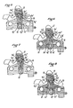
- Figure 3 illustrates the use of the slipper for the treatment of flat foot with ankle instability characterized more particularly by ligament instability of the ankle, heel instability, sub-scaphoid sagging and a flat forefoot.
- Figure 4 corresponds to a hollow foot with instability of the ankle and claw toes.
- the sub- and retro-capitals bars are isolated by welding the passages 6a ′ and 6c ′, the external sub-cuboid support 16, the tallon landlocking 19 and the parts forming an ankle 20 and 21.
- Figure 5 concerns the treatment of a typically feminine hollow foot.
- the sub-capital bar 13 is isolated by welding the two passages 6a ', after having inflated it to normal pressure. The pressure is then reduced and the anterior capital bar 12, the front part of the retro-capital bar 14, the sub-scaphoid supports 17-18, the internal sub-cuboid support 15 and possibly the anterior ankle parts 20 are isolated.
- the sub-cuboid and the retro-capital bar can be isolated by welding the passage 6f "to avoid the transmission of air between the two bearings.
- Figure 6 corresponds to the indication of a hollow anterior anterior arcuate foot with hammer toes, requiring an ankle, a wedge heel, sub-cuboid support and an ante-capital bar.
- the sub-capital and retro-capital bars are isolated by welding passages 6a 'and 6c', the passage 6d 'is closed between the ante-capital bar 12 and the sub-scaphoid supports 17-18, the passage 6f 'between the sub-scaphoid and the heel wedge, the passages 6i' and the passage 6g 'between the sub-cuboid and the anterior part of the ankle joint after which the intercommunicating cavities are inflated.
- welds 6 0 'substituted for welds 6c' it is possible, by welds 6 0 'substituted for welds 6c', to pressurize the rear strip of the retro-capital part and also to isolate after inflation the different zones by closing the passages 6d ', 6h', etc. .
- Figure 7 illustrates the treatment of a flat foot with spread out forefoot. After moderate inflation, a lateral part of the sub-capital bar and the front strip of the retro-capital bar are isolated by the welds 6a ′, 6b ′′ and 6p ′. internal scaphoid and sub-cuboid 15 and 17 after which the other cavities of the sole are inflated which can be isolated between them and isolate parts forming the ankle which can be brought to a moderate pressure.
- Figure 8 illustrates the treatment of a hollow foot with convex forefoot.
- a lateral part of the sub-capital bar is isolated by closing the passage 6b 'and a lateral passage 6a'.
- a moderate pressure is then established and closes the passages 6f ', 6i', 6d ', 6 0 ', 6p ', 6g' and 6e 'indicated to isolate at this pressure the rear strip of the retro-capital bar the sub-scaphoid internal 17, the sub-scuboid 15-16 and the anterior parts of the ankle, after which the pressure is inflated to normal pressure and the various inflated pads are isolated if necessary.
Abstract
Description
La présente invention concerne les articles chaussants, ce terme englobant les semelles rapportées dans les chaussures de tous types, les tiges basses et montantes, associées ou non à une semelle, incorporées dans les mêmes chaussures et les chaussons ou articles chaussants légers qui peuvent être portés seuls ou placés dans d'autres articles chaussants.The present invention relates to footwear, this term encompassing the soles added in shoes of all types, the uppers and uppers, associated or not with a sole, incorporated in the same shoes and the slippers or light footwear which can be worn. alone or placed in other footwear.
La présente invention a plus spécialement pour but de réaliser un article chaussant orthopédique susceptible d'assurer un soutien ou maintien sélectif des différentes parties du pied, éventuellement de la jambe, associé ou non à une contention de certaines de ces parties. L'article chaussant, du fait des ses caractéristiques, peut également être utilisé comme élément de confort dans les chaussures de sport et autres articles chaussants d'usage courant.The present invention more specifically aims to produce an orthopedic footwear capable of providing selective support or maintenance of the different parts of the foot, possibly of the leg, associated or not with a compression of some of these parts. The footwear, because of its characteristics, can also be used as a comfort element in sports shoes and other footwear in common use.
On a déjà proposé des articles chaussants gonflables de conceptions très diverses. Dans ces articles connus la partie gonflable peut être limitée à la semelle, à la tige ou à une partie de celle-ci, notamment à l'emboîtement du tarse, ou entourer une partie importante du pied et même remonter pour emboîter la jambe comme dans les chaussures de ski, comme décrit dans FR-A 2144464.Inflatable footwear of very different designs has already been proposed. In these known articles, the inflatable part can be limited to the sole, to the upper or to a part thereof, in particular to the interlocking of the tarsus, or to surround a large part of the foot and even to go back up to fit the leg as in ski boots, as described in FR-A 2144464.
La ou les chambres constituant la partie gonflable sont réalisées par des poches étanches rapportées éventuellement amovibles comme décrit dans US-A 4083127, des réseaux de tubes ou des cavités ménagées notamment dans la semelle comme décrit dans FR-A 4083127, des réseaux de tubes ou des cavités ménagées notamment dans la semelle comme décrit dans FR-A 2458239 et les différentes chambres sont en communication les unes avec les autres lorsque l'article est réellement gonflable mais elles peuvent être isolées lorsqu'il s'agit d'une semelle «pneumatique».The chamber or chambers constituting the inflatable part are produced by sealed waterproof pockets optionally removable as described in US-A 4083127, networks of tubes or cavities formed in particular in the sole as described in FR-A 4083127, networks of tubes or cavities formed in particular in the sole as described in FR-A 2458239 and the different chambers are in communication with each other when the article is actually inflatable but they can be isolated when it is a "pneumatic" sole "
Les inconvénients des articles chaussans gonflables antérieurs résident dans la pression de gonflage uniforme de toutes les chambres et dans l'instabilité d'une semelle comportant des chambres étendues en intercommunication, l'air étant, pendant l'usage, chassé des parties les plus chargées vers les parties les moins chargées. L'avantage de ces articles est par contre d'assurer un meilleur confort et d'absorber les chocs pendant la marche et la course. En outre ces articles chaussants sont standardisés et ne présentent qu'une possibilité d'adaptation très faible au pied à chausser, savoir une pointure et une pression de gonflage. Enfin ils ne permettent pas de répartir les coussins gonflés en fonction des caractéristiques morphologiques du pied à chausser. Ces inconvénients se retrouvent notamment das FR-A 2 458 239 dans lequel la semelle comporte des chambres à air réparties en chambres communicantes et chambres non communicantes. Il est proposé dans ce brevet de gonfler les chambres non communicantes à des pression différentes mais aucun moyen pratiques n'est décrit pour gonfler les différentes chambres à des pressions différentes.The disadvantages of previous inflatable footwear reside in the uniform inflation pressure of all the chambers and in the instability of a sole comprising extended chambers in intercommunication, the air being, during use, expelled from the most loaded parts. to the less loaded parts. The advantage of these articles, on the other hand, is to provide better comfort and absorb shocks during walking and running. In addition, these footwear is standardized and presents only a very slight possibility of adaptation to the foot, namely a size and an inflation pressure. Finally, they do not allow the inflated cushions to be distributed according to the morphological characteristics of the foot to be fitted. These drawbacks are found in particular in FR-A 2 458 239 in which the sole comprises air chambers distributed in communicating rooms and non-communicating rooms. It is proposed in this patent to inflate the non-communicating chambers to different pressures, but no practical means is described for inflating the different chambers to different pressures.
L'invention a pour but de créer un article chaussant gonflable qui remédie aux inconvénients et insuffisances des articles du même genre antérieurement connus et qui, de par sa constitution, est susceptible de réaliser un véritable article orthopédique.The invention aims to create an inflatable footwear which overcomes the disadvantages and inadequacies of articles of the same kind previously known and which, by its constitution, is capable of producing a real orthopedic article.
Le procédé de réalisation d'un article chaussant gonflé pneumatiquement à des pressions différentes dans ses différentes zones dans lequel on utilise une ébauche constituée par un ensemble de cavités intercommuniquant par des passages de section réduite et reliées à au moins un raccord de gonflage, est caractérisé en ce que l'on gonfle l'ébauche à la pression recherchée pour la cavité la plus éloignée du raccord et isole celle-ci en obturant les passages assurant sa mise en communication avec les autres cavités de l'ébauche et répète l'opération successivement pour chaque cavité non encore gonflée et la plus éloignée du raccord de gonflage en modifiant la pression jusqu'à ce que toutes les cavités soient gonflées aux pressions voulues et isolées.The method for producing an article of footwear inflated pneumatically to different pressures in its different zones in which a blank is used consisting of a set of cavities intercommunicating by passages of reduced section and connected to at least one inflation fitting, is characterized in that the blank is inflated to the desired pressure for the cavity furthest from the fitting and isolates the latter by closing the passages ensuring its communication with the other cavities of the blank and repeating the operation successively for each cavity not yet inflated and furthest from the inflation fitting by modifying the pressure until all the cavities are inflated to the desired pressures and isolated.
L'ébauche d'article chaussant pour la mise en oeuvre du procédé conforme à l'invention présente sur sa surface des cavités intercommuniquant par des passages de section réduite et reliées à au moins un raccord de gonflage et est caractérisée en ce qu'au moins certains des passages de section réduite assurant l'intercommunication entre le raccord de gonflage et certaines des cavités, sont obturables après gonflage pneumatique des cavités.The draft footwear for the implementation of the method according to the invention has on its surface cavities intercommunicating by passages of reduced section and connected to at least one inflation fitting and is characterized in that at least some of the passages of reduced section ensuring intercommunication between the inflation fitting and some of the cavities, can be closed after pneumatic inflation of the cavities.
Dans l'article chaussant gonflé obtenu par le procédé conforme à l'invention, on évite la circulation d'air entre les cavités laquelle est responsable de l'instabilité de la semelle, on peut gonfler plus ou moins certaines cavités pour réaliser des barres de soutien anté-capitale, rétro-capitale ou sous-capitale, des soutiens sous scaphoïdien ou sous cuboïdien, un enclavement talonnier ou une chevillère parfaitement adaptés au pied, et, de ce fait, traiter médicalement des mal-positions, sub-luxations ou luxations, traumatiques ou congénitales, du couple de torsion astragalo-calcanéen résultant d'une insuffisance ligamentaire ou d'une insuffisance musculaire des valgisants et du court péronier latéral.In the inflated footwear obtained by the process according to the invention, air circulation between the cavities is avoided which is responsible for the instability of the sole, it is possible to inflate more or less certain cavities to make bars of ante-capital, retro-capital or sub-capital support, support under the scaphoid or under the cuboid, a wedge heel or ankle brace perfectly suited to the foot, and, therefore, medically treat mal-positions, sub-luxations or dislocations , traumatic or congenital, of the astragalo-calcaneal torsion couple resulting from a ligament insufficiency or a muscular insufficiency of the valgisants and the short lateral peroneal.
Lorsque, dans l'article chaussant gonflé obtenu, certaines parties correspondant à certaines cavités doivent assurer une contention qui peut être variable dans le temps, par exemple au cours de l'évolution de la mal-position, ou qui peut varier parce que l'assemblage de forme de ces parties n'est pas fixe, par exemple l'assemblage des parties constituant une chevillère qui doivent être séparées pour chausser l'article, les cavités de ces parties restent de préférence en communication avec le ou les raccords de gonflage.When, in the inflated footwear obtained, certain parts corresponding to certain cavities must provide a compression which can be variable over time, for example during the evolution of the mal-position, or which can vary because the shape assembly of these parts is not fixed, for example the assembly of the parts constituting an ankle which must be separated to fit the article, the cavities of these parts preferably remain in communication with the inflation fitting (s).
Selon une autre caractéristique de la l'invention, l'ensemble de la poche gonflable subdivisée en les différentes cavités, est solidarisé avec au moins une peausserie ou couche de doublage disposées sur ses deux faces.According to another characteristic of the invention, the assembly of the inflatable pocket subdivided into the different cavities, is secured with at least one skin or lining layer arranged on its two faces.
Selon un mode de réalisation préférentiel, au moins certaines cavités sont préformées dans leur déformation par des éléments de jonction réunissant les deux parois de la cavité concernée de manière à éviter la déformation en ballonet de ladite cavité sous l'effet de la pression de gonflage. L'une des parois de la cavité peut être réalisée en un matériau thermoformable, ladite paroi étant préformée sensiblement à la forme qu'elle doit avoir après gonflage pneumatique dans l'article chaussant terminé.According to a preferred embodiment, at least certain cavities are preformed in their deformation by junction elements joining the two walls of the cavity concerned so as to avoid the balloon deformation of said cavity under the effect of the inflation pressure. One of the walls of the cavity can be made of a thermoformable material, said wall being preformed substantially to the shape which it must have after pneumatic inflation in the finished footwear.
De préférence les deux parois de la poche gonflable sont en un matériau thermosoudable, la subdivision en les différentes cavités et les éléments de jonction étant réalisés par des thermosoudures. En pratique les deux parois sont réalisées par des feuilles de polyuréthane et les thermosoudures sont réalisées par soudage à haute fréquence. Dans ce cas et selon le mode de réalisation préférentiel, les passages de section réduite obturables sont réalisés par des interruptions des thermosoudures de l'ébauche et leur obturation pendant la mise en oeuvre du procédé est assurée par une thermosoudure. De préférence les emplacements des passages obturables de communication entre les cavités sont repérés sur au moins une des couches ou peausseries de doublage, par exemple par des fenêtres d'engagement des électrodes de soudage.Preferably the two walls of the inflatable bag are made of a heat-sealable material, the subdivision into the different cavities and the junction elements being produced by heat-sealings. In practice, the two walls are made of polyurethane sheets and the heat seals are made by high frequency welding. In this case and according to the preferred embodiment, the passages of closable reduced section are produced by interruptions of the heat seals of the blank and their sealing during the implementation of the process is ensured by a heat seal. Preferably, the locations of the closable communication passages between the cavities are identified on at least one of the lining layers or skins, for example by windows for engaging the welding electrodes.
De préférence la surface de la semelle est subdivisée en une zone d'enclavement talonnier, des zones de soutien sous-scaphoïdienne et sous- cuboïdienne, des zones correspondant aux barres rétro-capitale, sous-capitale et anté-capitale et la semelle est associée avec une chevillère. Certaines des zones peuvent elles-même être subdivisées pour que leurs différentes parties puissent être gonflées différemment. Il en est ainsi notamment des parties constituant la chevillère qui sont subdivisées en chambres verticales et de la barre sous-capitale subdivisée en chambres longitudinales.Preferably the sole surface is subdivided into a heel wedge zone, sub-scaphoid and sub-cuboid support zones, zones corresponding to the retro-capital, sub-capital and ante-capital bars and the sole is associated. with an ankle brace. Some of the zones can themselves be subdivided so that their different parts can be inflated differently. This is particularly so of the parts constituting the ankle which are subdivided into vertical chambers and of the sub-capital bar subdivided into longitudinal chambers.
L'invention pourra être mieux comprise à la lecture de la description du procédé appliqué à la réalisation d'un chausson orthopédique, cette descpription étant faite avec référence aux dessins ci-annexés dans lesquels:
- La figure 1 est une vue en plan du tracé de l'ébauche utilisée dans le procédé;
- la figure 2 est une vue en coupe par II-II de figure 1;
- les figures 3 à 8 illustrent différentes combinaisons susceptibles d'être réalisées avec le chausson orthopédique de l'invention pour assurer divers traitements orthopédiques.
- Figure 1 is a plan view of the outline of the blank used in the process;
- Figure 2 is a sectional view through II-II of Figure 1;
- Figures 3 to 8 illustrate different combinations that can be made with the orthopedic liner of the invention to provide various orthopedic treatments.
Dans les dessins, les références 1 et 2 désignent les feuilles de polyuréthane constituant la paroi supérieure et la paroi inférieure de la poche gonflable; 3 désigne la doublure textile appliquée sur la paroi supérieure et 4 la peausserie appliquée sur la paroi inférieure. Les thermosoudures de formage sont désignées par 5 et les différents passages par la référence 6 affectée d'une lettre et éventuellement d'un exposant lorsqu'ils sont prévus pour être obturés. La référence 7 désigne un orifice ou fenêtre dans la peausserie 4 pour le passage des électrodes de soudage. La référence 8 désigne les bandes d'assemblage de la partie formant chevillère derrière le tendon d'Achille, la référence 9 les bandes de fermeture, par exemple garnies en tissu adhérant du type vendu sous la marque «Velcro», de la partie avant de la chevillère et 10 les fenêtres de dégagement des malléoles. La référence 11 désigne le raccord de gonflage.In the drawings,
Dans les figures 1 et 2, le chausson représenté est spécifique d'un pied droit mais il est possible, en assemblant des feuilles de polyuréthane à plat et non préformées et des peausseries identiques sur les deux faces, de réaliser une ébauche utilisable pour les deux pieds.In FIGS. 1 and 2, the liner shown is specific for a straight foot, but it is possible, by assembling polyurethane sheets flat and not preformed and identical leathers on both sides, to produce a blank usable for both feet.
La surface de l'ébauche est répartie en diverses zones respectivement la barre anté-capitale 12, la barre sous-capitale 13, la barre rétro-capitale 14, les soutiens sous cuboïdens interne 15 et externe 16, les soutiens sous-scaphoïdens interne 17 et externe 18, l'enclavement talonnier 19, les parties antérieures 20 de la chevillère et les parties postérieures 21. Les parties postérieures 21 de la chevillère sont en communication par un canal 23 contournant le talon. Les barres sous-capitale 13 et rétro-capitale 15 et les parties de la chevillère sont subdivisées par des thermosoudures de pontage 5a et la feuille de polyuréthane 2 est thermoformée dans les parties formant la chevillère pour donner des cavités tubulaires 22 de plus grande section sous une pression de gonflage modérée. Les épaisseurs sont exagérées dans la figure 2.The surface of the blank is divided into various zones respectively the anterior-
La partie sous-capitale 13 est en communication avec la cavité de la barre anté-capitale 12 par des passages 6a et la partie sous-capitale peut être subdivisée par soudage de passages 6b. La partie rétro-capitale 14 communique avec la barre anté-capitale par des passages obturables 6c. La barre anté-capitale communique avec les soutiens sous-cuboïdien et sous-scaphoïdien par des passages obturables 6d; les soutiens interne et externe, sous-cuboïdien et sous-scaphoïdien, sont en communication par des passages obturables 6e. Les soutiens sous-cuboidien et sous-scaphoïdien 16 et 18 communiquent avec l'enclavement talonnier 19 par des passages obturables 6f et avec les parties de chevilles antérieures 20 par des passages 6g. L'enclavement talonnier communique avec les parties de chevillère postérieures par des passages 6h et les parties de chevillère antérieures et postérieures communiquent ensemble par des passages 6i. L'une parties de chevillère postérieure est en communication avec la valve de gonflage 11.The
La figure 3 illustre l'utilisation du chausson pour le traitement du pied plat avec une instabilité de la cheville caractérisé plus particulièrement par une instabilité ligamentaire de la cheville, une instabilité talonnière, un affaissement sous-scaphoïdien et un avant pied plat. On obture par soudure haute fréquence l'un des passages 6d' entre les sous-cuboïdiens et la barre anté-capitale, le passage 6e' entre les sous-scaphoïdiens interne et externe, le passage 6f entre l'enclavement talonnier et les sous-cuboïdiens et on fongle très modérement après quoi on obture les deux passages 6i' et le passage 6g' entre la partie de chevillère antérieure et les sous-scaphoïdien et on fongle à une pression normale les barres anté-, sous- et rétro-capitales, le soutien sous-scaphoïdien externe, l'enclavement talonnier et les parties postérieures de la chevillère.Figure 3 illustrates the use of the slipper for the treatment of flat foot with ankle instability characterized more particularly by ligament instability of the ankle, heel instability, sub-scaphoid sagging and a flat forefoot. One of the
La figure 4 correspond à un pied creux avec instabilité de la cheville et orteils en griffes. Après gonflage modéré, on isole les barres sous- et rétro-capitales par soudage des passages 6a' et 6c', le soutien sous-cuboïdien externe 16, l'enclavement tallonier 19 et les parties formant chevillère 20 et 21.Figure 4 corresponds to a hollow foot with instability of the ankle and claw toes. After moderate inflation, the sub- and retro-capitals bars are isolated by welding the
La figure 5 concerne le traitement d'un pied creux typiquement féminin. Dans le procédé de traitement, on isole la barre sous-capitale 13 par soudage des deux passages 6a', après l'avoir gonflée à pression normale. On réduit alors la pression et isole la barre anté-capitale 12, la partie avant de la barre rétro-capitale 14, les soutiens sous-scaphoïdiens 17-18, le soutien sous-cuboïdien interne 15 et éventuellement les parties de chevillère antérieures 20 par soudage du passage 6d' entre le sous-cuboïdien externe et la barre anté-capitale, du passage 6e' entre les sous-cuboïdien interne et externe, de passages 61' et m' entre les extrémités des soudures transversales de la barre rétro-capitale, du passage 6f' entre l'enclavement talonnier et le soutien sous-scaphoïdien et des passages 6i' ou 6j'. On gonfle ensuite la partie arrière de la barre rétro-capitale, le soutien sous-cuboïdien et l'enclavement talonnier ainsi que les parties formant chevillère. Le sous-cuboïdien et la barre rétro-capitale peuvent être isolés par soudage du passage 6f" pour éviter la transmission d'air entre les deux coussinets.Figure 5 concerns the treatment of a typically feminine hollow foot. In the treatment process, the
La figure 6 correspond à l'indication d'un pied creux antérointerne arciforme avec orteils en marteaux, nécessitant une chevillère, un enclavement talonnier, un soutien sous-cuboïdien et une barre anté-capitale. Après gonflage modéré, on isole les barres sous-capitale et rétro-capitale par soudage des passages 6a' et 6c', on obture le passage 6d' entre la barre anté-capitale 12 et les soutiens sous-scaphoïdiens 17-18, le passage 6f' entre les sous-scaphoïdiens et l'enclavement talonnier, les passages 6i' et le passage 6g' entre les sous cuboïdiens et la partie antérieure de la chevillère après quoi on gonfle les cavités inter- communicantes. Il est possible, par des soudures 60' substituées aux soudures 6c', de mettre sous pression la bande arrière de la partie rétro-capitale et également d'isoler après gonflage les différentes zones en fermant les passages 6d', 6h', etc.Figure 6 corresponds to the indication of a hollow anterior anterior arcuate foot with hammer toes, requiring an ankle, a wedge heel, sub-cuboid support and an ante-capital bar. After moderate inflation, the sub-capital and retro-capital bars are isolated by
La figure 7 illustre le traitement d'un pied plat avec avant pied étalé. Après gonflage modéré, on isole par les soudures 6a', 6b" et 6p' une partie latérale de la barre sous-capitale et la bande avant de la barre rétro-capitale. On isole également par obturation des passages 6e', les sous-scaphoïdien et sous-cuboïdien internes 15 et 17 après quoi on gonfle les autres cavités de la semelle que l'on peut isoler entre elles et isoler des parties formant la chevillère qui peuvent être ramenées à une pression modérée.Figure 7 illustrates the treatment of a flat foot with spread out forefoot. After moderate inflation, a lateral part of the sub-capital bar and the front strip of the retro-capital bar are isolated by the
La figure 8 illustre le traitement d'un pied creux avec avant pied convexe. Après gonflage à une pression moyenne on isole par obturation du passage 6b' et d'un passage latéral 6a', une partie latérale de la barre sous-capitale. On établit ensuite une pression modérée et obture les passages 6f', 6i', 6d', 60', 6p', 6g' et 6e' indiqués pour isoler à cette pression la bande arrière de la barre rétro-capitale le sous-scaphoïdien interne 17, les sous-scuboïdiens 15-16 et les parties antérieures de la chevillère après quoi on gonfle à pression normale et isole si nécessaire les divers coussinets gonflés.Figure 8 illustrates the treatment of a hollow foot with convex forefoot. After inflation at a medium pressure, a lateral part of the sub-capital bar is isolated by closing the passage 6b 'and a
Les indications thérapeutiques données ci- dessus à titre d'exemples illustrent parfaitement l'intérêt technique de l'article chaussant conforme à l'invention.The therapeutic indications given above by way of examples perfectly illustrate the technical advantage of the footwear according to the invention.
Claims (10)
Priority Applications (1)
| Application Number | Priority Date | Filing Date | Title |
|---|---|---|---|
| AT83400922T ATE24100T1 (en) | 1982-05-14 | 1983-05-06 | METHOD OF MAKING AN INFLATABLE SHOE WITH DIFFERENT PRINTS AT DIFFERENT PLACES AND BLANK FOR MAKING SUCH SHOE. |
Applications Claiming Priority (2)
| Application Number | Priority Date | Filing Date | Title |
|---|---|---|---|
| FR8208541A FR2526643A1 (en) | 1982-05-14 | 1982-05-14 | METHOD FOR MAKING PUSHED FOOTWEAR ARTICLES AT DIFFERENT PRESSURES IN THEIR DIFFERENT ZONES AND DRAFT FOR ITS IMPLEMENTATION |
| FR8208541 | 1982-05-14 |
Publications (2)
| Publication Number | Publication Date |
|---|---|
| EP0094868A1 EP0094868A1 (en) | 1983-11-23 |
| EP0094868B1 true EP0094868B1 (en) | 1986-12-10 |
Family
ID=9274093
Family Applications (1)
| Application Number | Title | Priority Date | Filing Date |
|---|---|---|---|
| EP83400922A Expired EP0094868B1 (en) | 1982-05-14 | 1983-05-06 | Method of manufacturing footwear inflated at different pressures in different regions, and rough shape for manufacturing such footwear |
Country Status (4)
| Country | Link |
|---|---|
| EP (1) | EP0094868B1 (en) |
| AT (1) | ATE24100T1 (en) |
| DE (1) | DE3368186D1 (en) |
| FR (1) | FR2526643A1 (en) |
Cited By (15)
| Publication number | Priority date | Publication date | Assignee | Title |
|---|---|---|---|---|
| US5416988A (en) | 1989-03-17 | 1995-05-23 | Nike, Inc. | Customized fit shoe and bladder therefor |
| US5765298A (en) | 1989-03-17 | 1998-06-16 | Nike, Inc. | Athletic shoe with pressurized ankle collar |
| US6374514B1 (en) | 2000-03-16 | 2002-04-23 | Nike, Inc. | Footwear having a bladder with support members |
| US6385864B1 (en) | 2000-03-16 | 2002-05-14 | Nike, Inc. | Footwear bladder with controlled flex tensile member |
| US6402879B1 (en) | 2000-03-16 | 2002-06-11 | Nike, Inc. | Method of making bladder with inverted edge seam |
| US6457262B1 (en) | 2000-03-16 | 2002-10-01 | Nike, Inc. | Article of footwear with a motion control device |
| US6571490B2 (en) | 2000-03-16 | 2003-06-03 | Nike, Inc. | Bladder with multi-stage regionalized cushioning |
| US7707745B2 (en) | 2003-07-16 | 2010-05-04 | Nike, Inc. | Footwear with a sole structure incorporating a lobed fluid-filled chamber |
| US7707744B2 (en) | 2003-07-16 | 2010-05-04 | Nike, Inc. | Footwear with a sole structure incorporating a lobed fluid-filled chamber |
| US7774955B2 (en) | 2005-10-03 | 2010-08-17 | Nike, Inc. | Article of footwear with a sole structure having fluid-filled support elements |
| US7810255B2 (en) | 2007-02-06 | 2010-10-12 | Nike, Inc. | Interlocking fluid-filled chambers for an article of footwear |
| US7950169B2 (en) | 2007-05-10 | 2011-05-31 | Nike, Inc. | Contoured fluid-filled chamber |
| US8540838B2 (en) | 2005-07-01 | 2013-09-24 | Reebok International Limited | Method for manufacturing inflatable footwear or bladders for use in inflatable articles |
| US8572786B2 (en) | 2010-10-12 | 2013-11-05 | Reebok International Limited | Method for manufacturing inflatable bladders for use in footwear and other articles of manufacture |
| US8657979B2 (en) | 2003-12-23 | 2014-02-25 | Nike, Inc. | Method of manufacturing a fluid-filled bladder with a reinforcing structure |
Families Citing this family (7)
| Publication number | Priority date | Publication date | Assignee | Title |
|---|---|---|---|---|
| GB2168234B (en) * | 1984-11-19 | 1988-04-27 | John Alan Drew | Orthopaedic footwear |
| US5353459A (en) * | 1993-09-01 | 1994-10-11 | Nike, Inc. | Method for inflating a bladder |
| FR2717350B1 (en) * | 1994-03-17 | 1996-05-10 | Jesus Garcia | Shoes for sports activities. |
| US5753061A (en) * | 1995-06-05 | 1998-05-19 | Robert C. Bogert | Multi-celled cushion and method of its manufacture |
| US6430843B1 (en) | 2000-04-18 | 2002-08-13 | Nike, Inc. | Dynamically-controlled cushioning system for an article of footwear |
| ITFO20110002A1 (en) * | 2011-04-11 | 2012-10-12 | Ebro Bondi | FOOTBALL FOR FOOTWEAR |
| US9737114B2 (en) | 2014-08-06 | 2017-08-22 | Nike, Inc. | Articles of footwear with upper incorporating chamber element |
Family Cites Families (4)
| Publication number | Priority date | Publication date | Assignee | Title |
|---|---|---|---|---|
| US2677906A (en) * | 1952-08-14 | 1954-05-11 | Reed Arnold | Cushioned inner sole for shoes and meth od of making the same |
| US3758964A (en) * | 1971-10-25 | 1973-09-18 | Onitsuka Co Ltd | Sports shoe |
| US4083127A (en) * | 1977-03-17 | 1978-04-11 | Hanson Industries Incorporated | Adjustable, pressure-compensating, custom fitting pads having predetermined amount of fitting material and their use in boots |
| IT7960923V0 (en) * | 1979-06-07 | 1979-06-07 | Garzia Carmine Bolla Luigi | INSOLE FOR FOOTWEAR AND SIMILAR PREPARATION MORE PARTIALLY COMMUNICATING AIR CHAMBERS SUITABLE TO DISTRIBUTE PRESSURE OVER THE ENTIRE PLANT OF THE FOOT. |
-
1982
- 1982-05-14 FR FR8208541A patent/FR2526643A1/en active Granted
-
1983
- 1983-05-06 DE DE8383400922T patent/DE3368186D1/en not_active Expired
- 1983-05-06 EP EP83400922A patent/EP0094868B1/en not_active Expired
- 1983-05-06 AT AT83400922T patent/ATE24100T1/en not_active IP Right Cessation
Cited By (22)
| Publication number | Priority date | Publication date | Assignee | Title |
|---|---|---|---|---|
| US5416988A (en) | 1989-03-17 | 1995-05-23 | Nike, Inc. | Customized fit shoe and bladder therefor |
| US5765298A (en) | 1989-03-17 | 1998-06-16 | Nike, Inc. | Athletic shoe with pressurized ankle collar |
| US6374514B1 (en) | 2000-03-16 | 2002-04-23 | Nike, Inc. | Footwear having a bladder with support members |
| US6385864B1 (en) | 2000-03-16 | 2002-05-14 | Nike, Inc. | Footwear bladder with controlled flex tensile member |
| US6402879B1 (en) | 2000-03-16 | 2002-06-11 | Nike, Inc. | Method of making bladder with inverted edge seam |
| US6457262B1 (en) | 2000-03-16 | 2002-10-01 | Nike, Inc. | Article of footwear with a motion control device |
| US6571490B2 (en) | 2000-03-16 | 2003-06-03 | Nike, Inc. | Bladder with multi-stage regionalized cushioning |
| US7707745B2 (en) | 2003-07-16 | 2010-05-04 | Nike, Inc. | Footwear with a sole structure incorporating a lobed fluid-filled chamber |
| US7707744B2 (en) | 2003-07-16 | 2010-05-04 | Nike, Inc. | Footwear with a sole structure incorporating a lobed fluid-filled chamber |
| US8657979B2 (en) | 2003-12-23 | 2014-02-25 | Nike, Inc. | Method of manufacturing a fluid-filled bladder with a reinforcing structure |
| US8540838B2 (en) | 2005-07-01 | 2013-09-24 | Reebok International Limited | Method for manufacturing inflatable footwear or bladders for use in inflatable articles |
| US8312643B2 (en) | 2005-10-03 | 2012-11-20 | Nike, Inc. | Article of footwear with a sole structure having fluid-filled support elements |
| US8302328B2 (en) | 2005-10-03 | 2012-11-06 | Nike, Inc. | Article of footwear with a sole structure having fluid-filled support elements |
| US8302234B2 (en) | 2005-10-03 | 2012-11-06 | Nike, Inc. | Article of footwear with a sole structure having fluid-filled support elements |
| US7810256B2 (en) | 2005-10-03 | 2010-10-12 | Nike, Inc. | Article of footwear with a sole structure having fluid-filled support elements |
| US7774955B2 (en) | 2005-10-03 | 2010-08-17 | Nike, Inc. | Article of footwear with a sole structure having fluid-filled support elements |
| US8656608B2 (en) | 2005-10-03 | 2014-02-25 | Nike, Inc. | Article of footwear with a sole structure having fluid-filled support elements |
| US7810255B2 (en) | 2007-02-06 | 2010-10-12 | Nike, Inc. | Interlocking fluid-filled chambers for an article of footwear |
| US7950169B2 (en) | 2007-05-10 | 2011-05-31 | Nike, Inc. | Contoured fluid-filled chamber |
| US8911577B2 (en) | 2007-05-10 | 2014-12-16 | Nike, Inc. | Contoured fluid-filled chamber |
| US9345286B2 (en) | 2007-05-10 | 2016-05-24 | Nike, Inc. | Contoured fluid-filled chamber |
| US8572786B2 (en) | 2010-10-12 | 2013-11-05 | Reebok International Limited | Method for manufacturing inflatable bladders for use in footwear and other articles of manufacture |
Also Published As
| Publication number | Publication date |
|---|---|
| DE3368186D1 (en) | 1987-01-22 |
| FR2526643B1 (en) | 1985-01-11 |
| ATE24100T1 (en) | 1986-12-15 |
| FR2526643A1 (en) | 1983-11-18 |
| EP0094868A1 (en) | 1983-11-23 |
Similar Documents
| Publication | Publication Date | Title |
|---|---|---|
| EP0094868B1 (en) | Method of manufacturing footwear inflated at different pressures in different regions, and rough shape for manufacturing such footwear | |
| EP0032084B1 (en) | Shoes, particularly sports shoes | |
| US3084695A (en) | Method of making arch supporting cushion innersole | |
| CN104981342B (en) | Band whether there is the article of footwear and its manufacture method of the chamber of the fluid filling of filling passage | |
| US5295314A (en) | Shoe with sole including hollow space inflatable through removable bladder | |
| CN103025188B (en) | There is the manufacture method of the contouring fluid filled chamber of tension member | |
| US4005532A (en) | Insulated insole construction | |
| US20110131832A1 (en) | Fluid-Filled Structure | |
| KR20190104255A (en) | Article of footwear having a flexible fluid-filled chamber | |
| US20230389654A1 (en) | Orthopedic insoles for use in open footwear | |
| EP1494627B1 (en) | Splint for a joint connection and methods for production of such a splint | |
| CN106687000A (en) | Articles of footwear with upper incorporating chamber element | |
| US6149852A (en) | Method for obtaining a shoe, and shoe obtained with said method | |
| US20180295939A1 (en) | Footwear with improved upper | |
| JPH05507220A (en) | Athletic shoes with inflatable bag | |
| FR2803495A1 (en) | FOAM FOOTWEAR SOLE, FOOTWEAR AND METHODS OF MAKING SAME | |
| USD979187S1 (en) | Sandal | |
| EP0470358A1 (en) | Innerboot with improved fit | |
| CN200987400Y (en) | Liquid shoe pad with massaging function | |
| CN110089799B (en) | Inflatable sports shoes | |
| FR2551394A1 (en) | WATERPROOF SHOE AND MANUFACTURING METHOD THEREOF | |
| CN210054768U (en) | Shoes capable of improving wrapping degree | |
| US1567714A (en) | Golosh or overshoe | |
| FR2973657A1 (en) | Method for producing three-dimensional insoles with support for shoe, involves compressing only one of elastic material layers into deeper level of depth of base walls of shaped mold cavities, during compression of material in cavities | |
| ITTV950072A1 (en) | ANKLE SUPPORT DEVICE, ESPECIALLY FOR SPORTS SHOES |
Legal Events
| Date | Code | Title | Description |
|---|---|---|---|
| PUAI | Public reference made under article 153(3) epc to a published international application that has entered the european phase |
Free format text: ORIGINAL CODE: 0009012 |
|
| AK | Designated contracting states |
Designated state(s): AT BE CH DE GB IT LI LU NL SE |
|
| 17P | Request for examination filed |
Effective date: 19840511 |
|
| ITF | It: translation for a ep patent filed |
Owner name: ING. ZINI MARANESI & C. S.R.L. |
|
| GRAA | (expected) grant |
Free format text: ORIGINAL CODE: 0009210 |
|
| AK | Designated contracting states |
Kind code of ref document: B1 Designated state(s): AT BE CH DE GB IT LI LU NL SE |
|
| REF | Corresponds to: |
Ref document number: 24100 Country of ref document: AT Date of ref document: 19861215 Kind code of ref document: T |
|
| REF | Corresponds to: |
Ref document number: 3368186 Country of ref document: DE Date of ref document: 19870122 |
|
| PG25 | Lapsed in a contracting state [announced via postgrant information from national office to epo] |
Ref country code: LU Free format text: LAPSE BECAUSE OF NON-PAYMENT OF DUE FEES Effective date: 19870531 |
|
| PGFP | Annual fee paid to national office [announced via postgrant information from national office to epo] |
Ref country code: NL Payment date: 19870531 Year of fee payment: 5 |
|
| PLBE | No opposition filed within time limit |
Free format text: ORIGINAL CODE: 0009261 |
|
| STAA | Information on the status of an ep patent application or granted ep patent |
Free format text: STATUS: NO OPPOSITION FILED WITHIN TIME LIMIT |
|
| 26N | No opposition filed | ||
| PG25 | Lapsed in a contracting state [announced via postgrant information from national office to epo] |
Ref country code: GB Effective date: 19880506 Ref country code: AT Effective date: 19880506 |
|
| PG25 | Lapsed in a contracting state [announced via postgrant information from national office to epo] |
Ref country code: SE Effective date: 19880507 |
|
| PG25 | Lapsed in a contracting state [announced via postgrant information from national office to epo] |
Ref country code: LI Effective date: 19880531 Ref country code: CH Effective date: 19880531 |
|
| BERE | Be: lapsed |
Owner name: TECHNISYNTHESE Effective date: 19880531 |
|
| PG25 | Lapsed in a contracting state [announced via postgrant information from national office to epo] |
Ref country code: NL Effective date: 19881201 |
|
| NLV4 | Nl: lapsed or anulled due to non-payment of the annual fee | ||
| REG | Reference to a national code |
Ref country code: CH Ref legal event code: PL |
|
| GBPC | Gb: european patent ceased through non-payment of renewal fee | ||
| PG25 | Lapsed in a contracting state [announced via postgrant information from national office to epo] |
Ref country code: DE Effective date: 19890201 |
|
| PG25 | Lapsed in a contracting state [announced via postgrant information from national office to epo] |
Ref country code: BE Effective date: 19890531 |
|
| EUG | Se: european patent has lapsed |
Ref document number: 83400922.7 Effective date: 19890518 |