EP0097905A2 - Water-air convector with chimney effect for space-heating, and method of producing such a convector - Google Patents
Water-air convector with chimney effect for space-heating, and method of producing such a convector Download PDFInfo
- Publication number
- EP0097905A2 EP0097905A2 EP83106033A EP83106033A EP0097905A2 EP 0097905 A2 EP0097905 A2 EP 0097905A2 EP 83106033 A EP83106033 A EP 83106033A EP 83106033 A EP83106033 A EP 83106033A EP 0097905 A2 EP0097905 A2 EP 0097905A2
- Authority
- EP
- European Patent Office
- Prior art keywords
- convector
- tube
- sleeves
- fins
- vertical
- Prior art date
- Legal status (The legal status is an assumption and is not a legal conclusion. Google has not performed a legal analysis and makes no representation as to the accuracy of the status listed.)
- Withdrawn
Links
Images

Classifications
-
- F—MECHANICAL ENGINEERING; LIGHTING; HEATING; WEAPONS; BLASTING
- F28—HEAT EXCHANGE IN GENERAL
- F28D—HEAT-EXCHANGE APPARATUS, NOT PROVIDED FOR IN ANOTHER SUBCLASS, IN WHICH THE HEAT-EXCHANGE MEDIA DO NOT COME INTO DIRECT CONTACT
- F28D1/00—Heat-exchange apparatus having stationary conduit assemblies for one heat-exchange medium only, the media being in contact with different sides of the conduit wall, in which the other heat-exchange medium is a large body of fluid, e.g. domestic or motor car radiators
- F28D1/02—Heat-exchange apparatus having stationary conduit assemblies for one heat-exchange medium only, the media being in contact with different sides of the conduit wall, in which the other heat-exchange medium is a large body of fluid, e.g. domestic or motor car radiators with heat-exchange conduits immersed in the body of fluid
- F28D1/04—Heat-exchange apparatus having stationary conduit assemblies for one heat-exchange medium only, the media being in contact with different sides of the conduit wall, in which the other heat-exchange medium is a large body of fluid, e.g. domestic or motor car radiators with heat-exchange conduits immersed in the body of fluid with tubular conduits
- F28D1/047—Heat-exchange apparatus having stationary conduit assemblies for one heat-exchange medium only, the media being in contact with different sides of the conduit wall, in which the other heat-exchange medium is a large body of fluid, e.g. domestic or motor car radiators with heat-exchange conduits immersed in the body of fluid with tubular conduits the conduits being bent, e.g. in a serpentine or zig-zag
- F28D1/0475—Heat-exchange apparatus having stationary conduit assemblies for one heat-exchange medium only, the media being in contact with different sides of the conduit wall, in which the other heat-exchange medium is a large body of fluid, e.g. domestic or motor car radiators with heat-exchange conduits immersed in the body of fluid with tubular conduits the conduits being bent, e.g. in a serpentine or zig-zag the conduits having a single U-bend
-
- F—MECHANICAL ENGINEERING; LIGHTING; HEATING; WEAPONS; BLASTING
- F28—HEAT EXCHANGE IN GENERAL
- F28F—DETAILS OF HEAT-EXCHANGE AND HEAT-TRANSFER APPARATUS, OF GENERAL APPLICATION
- F28F21/00—Constructions of heat-exchange apparatus characterised by the selection of particular materials
- F28F21/06—Constructions of heat-exchange apparatus characterised by the selection of particular materials of plastics material
- F28F21/062—Constructions of heat-exchange apparatus characterised by the selection of particular materials of plastics material the heat-exchange apparatus employing tubular conduits
- F28F21/063—Constructions of heat-exchange apparatus characterised by the selection of particular materials of plastics material the heat-exchange apparatus employing tubular conduits for domestic or space-heating systems
Definitions
- the number of concentric sleeves is nine.
- the wall of the tube is 0.8 mm thick, as are the fins.
- the tube with its two fins has a height of 21.6 mm, and it makes three complete turns in each sleeve.
- the distance between two fins facing two neighboring sleeves is 7 mm.
- Vertical spacers E (see Figures 3 and 4) maintain the positions of the sleeves while letting the air circulate vertically.
Abstract
Description
L'invention concerne un convecteur eau-air à effet de cheminée pour chauffer un local. Elle s'étend en outre à un procédé de fabrication d'un tel convecteur.The invention relates to a water-air convector with a chimney effect for heating a room. It further extends to a method of manufacturing such a convector.
On sait que les installations dites de "chauffage central" pour le chauffage des locaux comportent, dans chaque pièce, un échangeur de chaleur du type radiateur ou convecteur, le convecteur étant, par rapport au radiateur, caractérisé par le fait que la quasi totalité de la chaleur est évacuée vers le local par convection d'air.It is known that the so-called "central heating" installations for space heating comprise, in each room, a heat exchanger of the radiator or convector type, the convector being, relative to the radiator, characterized in that almost all of the heat is removed to the room by air convection.
Il est connu de réaliser les convecteurs eau-air à l'aide de tôles d'acier constituant d'une part des conduites pour l'eau chaude d'autre part des ailettes qui sont échauffées par ces conduites par conduction thermique dans le métal et qui transmettent efficacement la chaleur à l'air grâce à leur grande surface de contact avec celui-ci. Il est également connu que cette transmission de chaleur est rendue plus active grâce à la vitesse ascensionnelle de l'air échauffé au contact de ces ailettes, et que cette vitesse peut être augmentée par effet de cheminée, c'est-à-dire en canalisant l'air dans une cheminée verticale autour et au-dessus des ailettes.It is known to produce water-air convectors using steel sheets constituting on the one hand pipes for hot water on the other hand fins which are heated by these pipes by thermal conduction in the metal and which efficiently transmit heat to the air thanks to their large contact surface with it. It is also known that this heat transmission is made more active by virtue of the rising speed of the air heated up in contact with these fins, and that this speed can be increased by chimney effect, that is to say by channeling the air in a vertical chimney around and above the fins.
Ces convecteurs classiques présentent l'inconvénient d'être relativement coûteux, car leur fabrication nécessite une forte dépense d'énergie, de nombreuses soudures, pliages, assemblages etc..... et de nécessiter un certain entretien (peinture) pour les protéger contre la rouille, c'est pourquoi on a proposé, dans le document FR-A n° 2.478.277, un convecteur eau-air à effet de cheminée, comportant :
- - des conduites d'eau chaude,
- - des surfaces d'échange thermique en contact thermique avec ces conduites
- - et une cheminée dont les parois sont disposées sensiblement verticalement autour et au-dessus de ces surfaces d'échange thermique pour canaliser et accélérer la circulation ascensionnelle de l'air échauffé au contact de ces surfaces, de manière à accélérer l'échange thermique entre ces surfaces et l'air circulant à leur contact, ce convecteur connu étant caractérisé par le fait que ces conduites et ces surfaces d'échange thermique sont constituées par des plaques à canaux internes, le matériau de ces plaques étant un haut polymère organique extrudable comportant une charge thermiquement conductrice.
- - hot water pipes,
- - heat exchange surfaces in thermal contact with these pipes
- - And a chimney whose walls are arranged substantially vertically around and above these heat exchange surfaces to channel and accelerate the upward circulation of the heated air in contact with these surfaces, so as to accelerate the heat exchange between these surfaces and the air flowing in contact with them, this known convector being characterized by the fact that these pipes and these heat exchange surfaces consist of plates with internal channels, the material of these plates being a high extrudable organic polymer comprising a thermally conductive filler.
Ces plaques à canaux internes peuvent présenter la forme de plaques verticales dont les canaux sont horizontaux et font saillies sur les deux faces de la plaque. La disposition utilisant des canaux permet d'avoir une vitesse de l'eau suffisante pour un bon échange thermique avec l'eau. Sa réalisation est assez facile. Le fait que les canaux sont horizontaux tend à provoquer un décollement de la couche limite à chaque passage de l'air ascendant au niveau d'un canal.These internal channel plates can be in the form of vertical plates, the channels of which are horizontal and protrude on both sides of the plate. The arrangement using channels makes it possible to have a sufficient water speed for good heat exchange with the water. Its realization is quite easy. The fact that the channels are horizontal tends to cause the boundary layer to become detached each time the ascending air passes through a channel.
Il est cependant apparu qu'on pouvait abaisser encore le prix de revient du convecteur.However, it appeared that the cost of the convector could be lowered further.
La présente invention a pour but d'augmenter encore la facilité de réalisation d'un convecteur eau-air à effet de cheminée pour chauffer un local, en conservant une bonne efficacité de transfert de chaleur, et sans imposer aucun entretien particulier du convecteur.The object of the present invention is to further increase the ease of making a water-air convector with a chimney effect for heating a room, while retaining good heat transfer efficiency, and without requiring any particular maintenance of the convector.
Elle a pour objet un convecteur eau-air à effet de cheminée pour chauffer un local, ce convecteur comportant :
- - une succession de panneaux chauffants verticaux parallèles laissant circuler entre eux des lames d'air ascendant, ces panneaux s'étendant selon une direction horizontale longitudinale, se succédant selon une direction horizontale transversale, étant constitués d'un haut polymère organique extrudable muni d'une charge thermiquement conductrice, et comportant chacun
- - des surfaces d'échange thermique verticales,
- - une succession verticale de tubes longitudinaux parcourus par de l'eau chaude, formés par des parois en continuité de matériau avec ces surfaces d'échange en formant saillie sur ces surfaces,
- - et une cheminée dont les parois sont disposées sensiblement verticalement autour et au-dessus de ces surfaces d'échange thermique pour canaliser et accélérer la circulation ascensionnelle de l'air échauffé au contact de ces surfaces, de manière à augmenter l'échange thermique entre ces surfaces et l'air circulant à leur contact,
- - ce convecteur étant caractérisé par le fait que lesdits tubes et surfaces d'échange thermique sont constitués par des manchons présentant chacun une paroi avant et une paroi arrière verticales longitudinales constituant lesdits panneaux, et deux parois latérales verticales incurvées raccordant ces parois avant et arrière, ces manchons s'entourant les uns les autres en formant une succession radiale à partir d'un volume central
- - chacun de ces manchons étant constitué par un tube portant des ailettes et enroulé en hélice et faisant plusieurs fois le tour du manchon et en montant d'un étage à chaque tour, ces ailettes étant verticales, s'étendant toutes deux selon la longueur de ce tube, et étant au nombre de deux, l'une en position supérieure, l'autre en position inférieure, ces deux ailettes occupant au moins 80% de l'intervalle vertical entre deux sections du même tube à deux étages adjacents, de manière à copstituer lesdites surfaces d'échange thermique sous la forme d'une paroi verticale sensiblement continue.
- - a succession of parallel vertical heating panels allowing ascending air spaces to circulate between them, these panels extending in a longitudinal horizontal direction, succeeding in a horizontal transverse direction, being made of a high extrudable organic polymer provided with a thermally conductive filler, and each comprising
- - vertical heat exchange surfaces,
- a vertical succession of longitudinal tubes traversed by hot water, formed by walls in continuity of material with these exchange surfaces by forming a projection on these surfaces,
- - And a chimney whose walls are arranged substantially vertically around and above these heat exchange surfaces to channel and accelerate the upward circulation of the heated air in contact with these surfaces, so as to increase the heat exchange between these surfaces and the air circulating in contact with them,
- - This convector being characterized in that said tubes and heat exchange surfaces consist of sleeves each having a longitudinal vertical front wall and rear wall constituting said panels, and two curved vertical side walls connecting these front and rear walls, these sleeves surrounding each other forming a radial succession from a central volume
- each of these sleeves being constituted by a tube carrying fins and wound in a helix and making several turns around the sleeve and going up one stage at each turn, these fins being vertical, both extending along the length of this tube, and being two in number, one in the upper position, the other in the lower position, these two fins occupying at least 80% of the vertical interval between two sections of the same tube with two adjacent stages, so co-constituting said heat exchange surfaces in the form of a substantially continuous vertical wall.
On adopte de plus, de préférence selon les circonstances, les dispositions suivantes :
- - les deux ailettes du tube sont, l'une large et l'autre étroite, les manchons successifs étant alternativement constitués par un tube dont l'ailette étroite est, en position inférieure et en position supérieure, de manière à permettre à la fois de décaler verticalement les tubes des manchons successifs pour éviter un rétrécissement excessif de la lame d'air ascendant, et de supporter les parties inférieures de ces manchons successifs sur un même support s'étendant horizontalement à partir du volume central. L'épaisseur des ailettes est de préférence sensiblement égale à celle de la paroi du tube.
- - the two fins of the tube are, one wide and the other narrow, the successive sleeves being alternately constituted by a tube whose narrow fin is in the lower position and in the upper position, so as to allow both vertically offset the tubes of the successive sleeves to avoid excessive narrowing of the rising air knife, and to support the lower parts of these successive sleeves on the same support extending horizontally from the central volume. The thickness of the fins is preferably substantially equal to that of the wall of the tube.
La présente invention a encore pour objet un procédé de fabrication d'un convecteur , ce procédé étant caractérisé par le fait que le tube est fabriqué en continu avec ses ailettes par une seule opération d'extrusion, puis sectionné en tronçons, puis cintré à chaud pour constituer les manchons.The present invention also relates to a method of manufacturing a convector, this method being characterized in that the tube is manufactured continuously with its fins by a single extrusion operation, then sectioned into sections, then bent hot to form the sleeves.
A l'aide des figures schématiques ci-jointes on va décrire ci-après, à titre non limitatif, comment l'invention peut être mise en oeuvre. Il doit être compris que les éléments décrits et représentés peuvent, sans sortir du cadre de l'invention, être remplacés par d'autres éléments assurant les mêmes fonctions techniques. Lorsqu'un même élément est représenté sur plusieurs figures il y est désigné par la même signe de référence.
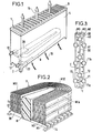
- La figure 1 représente une vue d'ensemble en perspective d'un convecteur selon l'invention.
- La figure 2 représente une vue en perspective coupée de ce eonveo- teur sans son boîtier formant cheminée.
- La figure 3 représente une vue en coupe de plusieurs manchons de ce convecteur.
- La figure 4 représente une vue en perspective à échelle agrandie de l'une des entretoises verticales équidistantes constituant des espaceurs pour la circulation de l'air entre les manchons successifs de ce convecteur.
- FIG. 1 represents an overall perspective view of a convector according to the invention.
- FIG. 2 represents a cut view in perspective of this unveiler without its casing forming a chimney.
- Figure 3 shows a sectional view of several sleeves of this convector.
- FIG. 4 represents a perspective view on an enlarged scale of one of the equidistant vertical spacers constituting spacers for the circulation of air between the successive sleeves of this convector.
Le convecteur qui est représenté sur la figure 1, comporte un boîtier rectangulaire 1 à parois verticales porté par quatre pieds 2 et constituant une cheminée 4 à section rectangulaire de 20 cm de large et de 75 cm de haut munie d'un couvercle perforé 6.The convector which is shown in FIG. 1 comprises a rectangular box 1 with vertical walls carried by four
Dans la cheminée, au bas de celle-ci, sont disposées neuf manchons verticaux concentriques constituant un échangeur thermique 8 alimenté en eau chaude par une arrivée haute 10, la sortie 12 étant au bas.In the chimney, at the bottom thereof, are arranged nine concentric vertical sleeves constituting a
La répartition du débit d'eau chaude en parallèle dans les neuf manchons verticaux est effectuée dans un collecteur d'entrée 20 situé à la partie supérieure de l'échangeur thermique, alimenté par l'arrivée haute 10.The distribution of the hot water flow in parallel in the nine vertical sleeves is carried out in an
De même, un collecteur de sortie 22 situé à la partie inférieure de l'échangeur thermique regroupe les débits d'eau en parallèle issus des neuf manchons verticaux, évacués par la sortie 12.Similarly, an
La circulation de l'air est représentée par les flèches 16. Elle part du fond perforé 14 du boîtier. l'air chauffé par l'échangeur s'élève dans la cheminée et sort par le couvercle 6.The air circulation is represented by the
Le matériau de cet échangeur peut être un mélange de polyéthylène haute densité avec 40% en poids de polyéthylène chloré, ce dernier comportant 35% de chlore en poids avec 2 à 2,5% d'un agent antioxydant classique (mélange de polyphénols alcoylés et de thiodipropionates) et un agent de couplage classique (1% d'un titanate organique). La charge est constituée par 80% en poids d'un mélange de noir de carbone avec 10% de fibres de carbone de 1 à 3 mm de long pour un diamètre. de 8 micromètres. Un tel matériau peut être mis en forme par extrusion et recevoir ultérieurement à chaud des déformations limitées.The material of this exchanger can be a mixture of high density polyethylene with 40% by weight of chlorinated polyethylene, the latter comprising 35% of chlorine by weight with 2 to 2.5% of a conventional antioxidant agent (mixture of alkylated polyphenols and of thiodipropionates) and a conventional coupling agent (1% of an organic titanate). Load consists of 80% by weight of a mixture of carbon black with 10% of carbon fibers from 1 to 3 mm long for a diameter. of 8 micrometers. Such a material can be shaped by extrusion and subsequently receive limited deformations when hot.
L'échangeur thermique 8 comporte comme connu :
- - une succession de panneaux chauffants verticaux parallèles laissant circuler entre eux des lames d'air ascendant, ces panneaux s'étendant selon une direction horizontale longitudinale, se succédant selon une direction horizontale transversale, étant constitués d'un haut polymère organique extrudable muni d'une charge thermiquement conductrice, et comportant chacun :
- - des surfaces d'échange thermique verticales,
- - une succession verticale de tubes longitudinaux parcourus par de l'eau chaude, formés par des parois en continuité de matériau avec ces surfaces d'échange en formant saillie sur ces surfaces,
- - et une cheminée dont les parois sont disposées sensiblement verticalement autour et au-dessus de ces surfaces d'échange thermique pour canaliser et accélérer la circulation ascensionnelle de l'air échauffé au contact de ces surfaces, de manière à augmenter l'échange thermique entre ces surfaces et l'air circulant à leur contact.
- - a succession of parallel vertical heating panels allowing ascending air spaces to circulate between them, these panels extending in a longitudinal horizontal direction, succeeding in a horizontal transverse direction, being made of a high extrudable organic polymer provided with a thermally conductive filler, and each comprising:
- - vertical heat exchange surfaces,
- a vertical succession of longitudinal tubes traversed by hot water, formed by walls in continuity of material with these exchange surfaces by forming a projection on these surfaces,
- - And a chimney whose walls are arranged substantially vertically around and above these heat exchange surfaces to channel and accelerate the upward circulation of the heated air in contact with these surfaces, so as to increase the heat exchange between these surfaces and the air flowing in contact with them.
Selon l'invention et comme représenté sur les figures 2 et 3, lesdits tubes et surfaces d'échange thermique sont constitués par des manchons présentant chacun une paroi avant et une paroi arrière verticales longitudinales constituant lesdits panneaux, et deux parois latérales verticales incurvées raccordant ces parois avant et arrière, ces manchons s'entourant les uns les autres en formant une succession radiale à partir d'un volume central - chacun de ces manchons étant constitué par un tube (T1, T2) portant des ailettes et enroulé en hélice et faisant plusieurs fois le tour du manchon et en montant d'un étage à chaque tour, ces ailettes étant verticales s'étendant toutes deux selon la longueur de ce tube, et étant au nombre de deux l'une en position supérieure (B1, B2), l'autre en position inférieure (A1, B2) ces deux ailettes occupant au moins 80% de l'intervalle vertical entre deux sections (Tla, T1b) du même tube (T1) à deux étages adjacents, de manière à constituer lesdites surfaces d'échange thermique sous la forme d'une paroi verticale sensiblement continue.According to the invention and as shown in Figures 2 and 3, said tubes and heat exchange surfaces are constituted by sleeves each having a front wall and a longitudinal vertical rear wall constituting said panels, and two curved vertical side walls connecting these front and rear walls, these sleeves surrounding each other by forming a radial succession from a central volume - each of these sleeves being constituted by a tube (T1, T2) carrying fins and wound in a helix and making several times around the sleeve and going up one stage at each turn, these fins being vertical both extending along the length of this tube, and being two in number one in the upper position (B1, B2) , the other in the lower position (A1, B2) these two fins occupying at least 80% of the vertical interval between two sections (Tla, T1b) of the same tube (T1) with two adjacent stages, so as to constitute said surfaces. these heat exchange in the form of a substantially continuous vertical wall.
De préférence, les deux ailettes du tube (T1, T2) sont, l'une large (B1, B2) et l'autre étroite (A1, A2) , les manchons successifs (M1, M2) étant alternativement constitués par un tube (T1, T2) dont l'ailette étroite (A1, A2) est, en position inférieure (A1) et en position supérieure ((A2), de manière à permettre à la fois de décaler verticalement les tubes des manchons successifs pour éviter un rétrécissement excessif de la lame d'air ascendant, et de supporter les parties inférieures de ces manchons successifs sur un même support (20) s'étendant horizontalement à partir du volume central (18).Preferably, the two fins of the tube (T1, T2) are, one wide (B1, B2) and the other narrow (A1, A2), the successive sleeves (M1, M2) being alternately constituted by a tube ( T1, T2), the narrow fin (A1, A2) of which is in the lower position (A1) and in the upper position ((A2), so as to allow both the tubes to be vertically offset from the successive sleeves to avoid shrinking excess of the rising air knife, and to support the lower parts of these successive sleeves on the same support (20) extending horizontally from the central volume (18).
La différence de largeur entre les ailettes étroites A1, A2 et les ailettes larges B1, B2 est choisie de manière que la section de passage offerte à l'air entre deux tubes voisins T1, T2 ne soit pas inférieure à celle offerte entre un tube T1 et l'ailette B2, du manchon voisin en regard de ce tube. Cette différence doit cependant rester suffisamment petite pour que la chaleur du tube parvienne facilement jusqu'à l'extrémité de l'ailette large.The difference in width between the narrow fins A1, A2 and the wide fins B1, B2 is chosen so that the passage section offered to the air between two neighboring tubes T1, T2 is not less than that offered between a tube T1 and the fin B2, of the neighboring sleeve opposite this tube. This difference must however remain small enough for the heat from the tube to easily reach the end of the wide fin.
De préférence encore, l'épaisseur des ailettes est sensiblement égale à celle de la paroi du tube.More preferably, the thickness of the fins is substantially equal to that of the wall of the tube.
Un tel échangeur peut être fabriqué d'une manière particulièrement simple.Such an exchanger can be manufactured in a particularly simple manner.
Lorsque le tube muni de deux ailettes est cintré à chaud pour constituer l'une des spires d'un manchon, la déformation résultante des ailettes constitue des éléments de surface cylindrique d'axe vertical, de telle sorte que les extrémités des ailettes de deux spires consécutives d'un même manchon restent en vis-à-vis, assurant la continuité de la paroi d'échange avec l'air.When the tube provided with two fins is bent hot to constitute one of the turns of a sleeve, the resulting deformation of the fins constitutes cylindrical surface elements of vertical axis, so that the ends of the fins of two turns consecutive of the same sleeve remain vis-à-vis, ensuring the continuity of the exchange wall with the air.
La mise en place de chaque spire d'un manchon s'effectue en prenant appui sur un ensemble d'entretoises verticales équidistantes constituant des espaceurs entre les manchons ; ces entretoises sont représentées sur la figure 4 ; elles sont disposées parallèlement aux veines d'air circulant verticalement entre les manchons ; ces entretoises assurent une répartition régulière de la vitesse de l'air et des échanges de chaleur.The positioning of each turn of a sleeve is carried out by resting on a set of equidistant vertical spacers constituting spacers between the sleeves; these spacers are shown in Figure 4; they are arranged parallel to the air streams flowing vertically between the sleeves; these spacers ensure an even distribution of air speed and heat exchange.
La répartition en parallèle du débit d'eau entre les divers manchons a pour effet :
- - de maintenir l'égalité des températures dans les spires en vis-à-vis des divers manchons,
- - de constituer une disposition régulière des tubes restant équidistants dans l'ensemble de l'échangeur,
- - de limiter convenablement la vitesse de circulation d'eau et la perte de charge.
- - to maintain equal temperatures in the turns vis-à-vis the various sleeves,
- - to constitute a regular arrangement of the tubes remaining equidistant throughout the exchanger,
- - appropriately limit the speed of water circulation and the pressure drop.
Dans le mode de réalisation particulier représenté, le nombre de manchons concentriques est de neuf. La paroi du tube est épaisse de 0,8 mm de même que les ailettes. Le tube présente avec ses deux ailettes une hauteur de 21,6 mm, et il fait trois tours complets dans chaque manchon. La distance entre deux ailettes en regard de deux manchons voisins est de 7 mm. Des entretoises verticales E (voir figures 3 et 4) assurent le maintien des positions des manchons tout en laissant l'air circuler verticalement.In the particular embodiment shown, the number of concentric sleeves is nine. The wall of the tube is 0.8 mm thick, as are the fins. The tube with its two fins has a height of 21.6 mm, and it makes three complete turns in each sleeve. The distance between two fins facing two neighboring sleeves is 7 mm. Vertical spacers E (see Figures 3 and 4) maintain the positions of the sleeves while letting the air circulate vertically.
Claims (4)
Applications Claiming Priority (2)
| Application Number | Priority Date | Filing Date | Title |
|---|---|---|---|
| FR8211084 | 1982-06-24 | ||
| FR8211084A FR2529309B1 (en) | 1982-06-24 | 1982-06-24 | WATER-AIR CONVECTOR WITH CHIMNEY EFFECT FOR HEATING A PREMISES |
Publications (2)
| Publication Number | Publication Date |
|---|---|
| EP0097905A2 true EP0097905A2 (en) | 1984-01-11 |
| EP0097905A3 EP0097905A3 (en) | 1984-10-24 |
Family
ID=9275365
Family Applications (1)
| Application Number | Title | Priority Date | Filing Date |
|---|---|---|---|
| EP83106033A Withdrawn EP0097905A3 (en) | 1982-06-24 | 1983-06-21 | Water-air convector with chimney effect for space-heating, and method of producing such a convector |
Country Status (2)
| Country | Link |
|---|---|
| EP (1) | EP0097905A3 (en) |
| FR (1) | FR2529309B1 (en) |
Cited By (15)
| Publication number | Priority date | Publication date | Assignee | Title |
|---|---|---|---|---|
| GB2158215A (en) * | 1984-04-26 | 1985-11-06 | Fook Chong Chai | Cooling plant |
| GB2192704A (en) * | 1986-07-16 | 1988-01-20 | Runtal Holding Co Sa | A room heating radiator body |
| EP0350453A1 (en) * | 1988-07-08 | 1990-01-10 | Arbonia Ag | Washbasin with Radiator |
| GB2243678A (en) * | 1990-05-01 | 1991-11-06 | Kevin Paul Hartley | Space heating radiators |
| EP0572187A2 (en) * | 1992-05-29 | 1993-12-01 | Anthony Joseph Cesaroni | Panel heat exchanger formed from tubes and sheets |
| US6059024A (en) * | 1995-09-08 | 2000-05-09 | Newcastle University Ventures Ltd. | Polymer film heat exchanger |
| US6253567B1 (en) * | 1998-09-17 | 2001-07-03 | Hitachi, Ltd. | Ice thermal storage type air conditioner and ice thermal storage tank |
| US7207377B2 (en) * | 2005-03-08 | 2007-04-24 | Denso Corporation | Heat exchanger |
| US20090139702A1 (en) * | 2007-11-30 | 2009-06-04 | Gordon Hogan | Heat exchanger |
| CN102639955A (en) * | 2009-09-18 | 2012-08-15 | 诺尔斯海德公司 | Multi tube heat exchanger |
| US20150107807A1 (en) * | 2013-10-17 | 2015-04-23 | MAHLE Behr GmbH & Co. KG | Heat exchanger |
| WO2015113525A1 (en) * | 2014-01-29 | 2015-08-06 | Tomton S.R.O. | Air conditioning body intended especially for hot water central heating |
| EP3521744A4 (en) * | 2016-09-28 | 2020-04-29 | Danfoss Micro Channel Heat Exchanger (Jiaxing) Co., Ltd. | Heat exchange assembly for heat exchanger, heat exchanger, and mold |
| CN111220007A (en) * | 2019-11-29 | 2020-06-02 | 四川金象赛瑞化工股份有限公司 | Heat exchange plate, heat exchanger, application of heat exchanger and washing cooling tower |
| EP4202341A3 (en) * | 2021-12-22 | 2023-09-06 | Schmöle GmbH | Heat exchanger baffle and method of making same |
Citations (8)
| Publication number | Priority date | Publication date | Assignee | Title |
|---|---|---|---|---|
| US1655531A (en) * | 1926-02-04 | 1928-01-10 | Bliss E W Co | Thin-walled metal radiator |
| FR971034A (en) * | 1951-01-11 | |||
| US2559272A (en) * | 1947-09-06 | 1951-07-03 | Ungarische Radiatoren Fabriks | Heat exchanger |
| GB872255A (en) * | 1958-03-10 | 1961-07-05 | Ici Ltd | Heat exchange apparatus |
| US3384167A (en) * | 1967-04-03 | 1968-05-21 | Javkin Simon | Band for heat exchange |
| FR2214097A1 (en) * | 1973-01-16 | 1974-08-09 | Atomenergi Ab | |
| FR2285588A1 (en) * | 1974-09-19 | 1976-04-16 | Hoechst Ag | FLAT RADIATOR IN THERMOPLASTIC MATERIAL |
| FR2478277A1 (en) * | 1980-03-14 | 1981-09-18 | Comp Generale Electricite | Hot water convector heater - has auxiliary heater above spaced vertical plastics sheets incorporating staggered horizontal flow channels |
-
1982
- 1982-06-24 FR FR8211084A patent/FR2529309B1/en not_active Expired
-
1983
- 1983-06-21 EP EP83106033A patent/EP0097905A3/en not_active Withdrawn
Patent Citations (8)
| Publication number | Priority date | Publication date | Assignee | Title |
|---|---|---|---|---|
| FR971034A (en) * | 1951-01-11 | |||
| US1655531A (en) * | 1926-02-04 | 1928-01-10 | Bliss E W Co | Thin-walled metal radiator |
| US2559272A (en) * | 1947-09-06 | 1951-07-03 | Ungarische Radiatoren Fabriks | Heat exchanger |
| GB872255A (en) * | 1958-03-10 | 1961-07-05 | Ici Ltd | Heat exchange apparatus |
| US3384167A (en) * | 1967-04-03 | 1968-05-21 | Javkin Simon | Band for heat exchange |
| FR2214097A1 (en) * | 1973-01-16 | 1974-08-09 | Atomenergi Ab | |
| FR2285588A1 (en) * | 1974-09-19 | 1976-04-16 | Hoechst Ag | FLAT RADIATOR IN THERMOPLASTIC MATERIAL |
| FR2478277A1 (en) * | 1980-03-14 | 1981-09-18 | Comp Generale Electricite | Hot water convector heater - has auxiliary heater above spaced vertical plastics sheets incorporating staggered horizontal flow channels |
Cited By (19)
| Publication number | Priority date | Publication date | Assignee | Title |
|---|---|---|---|---|
| GB2158215A (en) * | 1984-04-26 | 1985-11-06 | Fook Chong Chai | Cooling plant |
| GB2158216A (en) * | 1984-04-26 | 1985-11-06 | Fook Chong Chai | Heat exchangers |
| GB2192704A (en) * | 1986-07-16 | 1988-01-20 | Runtal Holding Co Sa | A room heating radiator body |
| EP0350453A1 (en) * | 1988-07-08 | 1990-01-10 | Arbonia Ag | Washbasin with Radiator |
| GB2243678A (en) * | 1990-05-01 | 1991-11-06 | Kevin Paul Hartley | Space heating radiators |
| EP0572187A2 (en) * | 1992-05-29 | 1993-12-01 | Anthony Joseph Cesaroni | Panel heat exchanger formed from tubes and sheets |
| EP0572187A3 (en) * | 1992-05-29 | 1994-04-27 | Anthony Joseph Cesaroni | |
| US6059024A (en) * | 1995-09-08 | 2000-05-09 | Newcastle University Ventures Ltd. | Polymer film heat exchanger |
| US6253567B1 (en) * | 1998-09-17 | 2001-07-03 | Hitachi, Ltd. | Ice thermal storage type air conditioner and ice thermal storage tank |
| US7207377B2 (en) * | 2005-03-08 | 2007-04-24 | Denso Corporation | Heat exchanger |
| US20090139702A1 (en) * | 2007-11-30 | 2009-06-04 | Gordon Hogan | Heat exchanger |
| CN102639955A (en) * | 2009-09-18 | 2012-08-15 | 诺尔斯海德公司 | Multi tube heat exchanger |
| US20150107807A1 (en) * | 2013-10-17 | 2015-04-23 | MAHLE Behr GmbH & Co. KG | Heat exchanger |
| WO2015113525A1 (en) * | 2014-01-29 | 2015-08-06 | Tomton S.R.O. | Air conditioning body intended especially for hot water central heating |
| RU181090U1 (en) * | 2014-01-29 | 2018-07-04 | ТОМТОН с.р.о. | DEVICE FOR AIR CONDITIONING, IN PARTICULAR, DESIGNED FOR CENTRAL WATER HEATING |
| EP3521744A4 (en) * | 2016-09-28 | 2020-04-29 | Danfoss Micro Channel Heat Exchanger (Jiaxing) Co., Ltd. | Heat exchange assembly for heat exchanger, heat exchanger, and mold |
| US11118839B2 (en) | 2016-09-28 | 2021-09-14 | Danfoss Micro Channel Heat Exchanger (Jiaxing) Co., Ltd. | Heat exchange assembly for heat exchanger, heat exchanger, and mold |
| CN111220007A (en) * | 2019-11-29 | 2020-06-02 | 四川金象赛瑞化工股份有限公司 | Heat exchange plate, heat exchanger, application of heat exchanger and washing cooling tower |
| EP4202341A3 (en) * | 2021-12-22 | 2023-09-06 | Schmöle GmbH | Heat exchanger baffle and method of making same |
Also Published As
| Publication number | Publication date |
|---|---|
| FR2529309A1 (en) | 1983-12-30 |
| EP0097905A3 (en) | 1984-10-24 |
| FR2529309B1 (en) | 1987-07-10 |
Similar Documents
| Publication | Publication Date | Title |
|---|---|---|
| EP0097905A2 (en) | Water-air convector with chimney effect for space-heating, and method of producing such a convector | |
| FR2705445A1 (en) | Plate heat exchanger. | |
| CH644684A5 (en) | ATMOSPHERIC HEATER. | |
| FR2527317A1 (en) | GAS OR LIQUID FUEL BOILER FOR THE PRODUCTION OF HOT WATER OR STEAM | |
| FR2595981A1 (en) | STACK OF SOLDERABLE THERMOPLASTIC MATERIAL PLATES | |
| FR3053067A1 (en) | SOLAR SWIMMING POOL | |
| EP2423630B1 (en) | Heat exchange device | |
| FR2478277A1 (en) | Hot water convector heater - has auxiliary heater above spaced vertical plastics sheets incorporating staggered horizontal flow channels | |
| FR2541442A1 (en) | HEAT EXCHANGER HAVING A MODULAR STRUCTURE AND METHOD FOR MANUFACTURING THE SAME | |
| EP2251612A1 (en) | Electric radiator with heat-transfer fluid made up of moulded modular elements | |
| EP0099835A2 (en) | Heat exchanger with a modular structure | |
| EP3354997B1 (en) | Boiler with improved efficiency | |
| EP1947386B1 (en) | Turbulator, in particular for a boiler with smoke pipes, and corresponding boiler | |
| BE1001466A6 (en) | Gas heat exchanger for air reheater - has parallel tubes containing conducting elements and equipped with external fins | |
| WO2015004359A1 (en) | Heat exchange device and method for making such a device | |
| EP1050721A1 (en) | Heat exchanger for a water heater | |
| FR2850451A1 (en) | Condensation heat exchanger for domestic application, has bundles of tubes mounted inside casing made of heat-resistant plastic material, containment mechanism to ensure mechanical containment of bundle for absorbing thrust loads | |
| BE1002337A6 (en) | High heat capacity gas to fluid heat exchanger | |
| FR2532404A1 (en) | Fluidised bed combustion chamber bottom | |
| FR2496861A1 (en) | Plate heat exchanger for two fluids - esp. where river water is used to heat halogenated hydrocarbon refrigerant | |
| FR2967488A1 (en) | Extrusion-blown polymer or glass parison nest plate for e.g. fluid-gas heat exchanger in diesel engine's exhaust gas cooling field, has external couplers provided on opposite ends of central area whose channels are separated by partitions | |
| BE851252A (en) | SOLAR ENERGY RECOVERY | |
| FR2530795A1 (en) | DEVICE FOR HEATING CONTAINERS AND / OR MAINTAINING SAME AT TEMPERATURE, FOR EXAMPLE FOR CONTAINERS CONTAINING MOLTEN METAL. | |
| EP2034264A2 (en) | Towel-drying branching radiator with optimised fluid circulation | |
| BE447645A (en) |
Legal Events
| Date | Code | Title | Description |
|---|---|---|---|
| PUAI | Public reference made under article 153(3) epc to a published international application that has entered the european phase |
Free format text: ORIGINAL CODE: 0009012 |
|
| AK | Designated contracting states |
Designated state(s): AT BE CH DE FR GB IT LI LU NL SE |
|
| PUAL | Search report despatched |
Free format text: ORIGINAL CODE: 0009013 |
|
| AK | Designated contracting states |
Designated state(s): AT BE CH DE FR GB IT LI LU NL SE |
|
| 17P | Request for examination filed |
Effective date: 19850423 |
|
| STAA | Information on the status of an ep patent application or granted ep patent |
Free format text: STATUS: THE APPLICATION HAS BEEN WITHDRAWN |
|
| 18W | Application withdrawn |
Withdrawal date: 19860107 |
|
| RIN1 | Information on inventor provided before grant (corrected) |
Inventor name: MOISSON-FRANCKHAUSER, FRANCOIS Inventor name: BERTHET, MICHEL Inventor name: DUBOIS, PIERRE |