EP0099043A2 - System for the control of electric energy consumption, preferably domestic - Google Patents
System for the control of electric energy consumption, preferably domestic Download PDFInfo
- Publication number
- EP0099043A2 EP0099043A2 EP83106516A EP83106516A EP0099043A2 EP 0099043 A2 EP0099043 A2 EP 0099043A2 EP 83106516 A EP83106516 A EP 83106516A EP 83106516 A EP83106516 A EP 83106516A EP 0099043 A2 EP0099043 A2 EP 0099043A2
- Authority
- EP
- European Patent Office
- Prior art keywords
- load computer
- devices
- switching
- load
- priority
- Prior art date
- Legal status (The legal status is an assumption and is not a legal conclusion. Google has not performed a legal analysis and makes no representation as to the accuracy of the status listed.)
- Granted
Links
Images

Classifications
-
- G—PHYSICS
- G01—MEASURING; TESTING
- G01R—MEASURING ELECTRIC VARIABLES; MEASURING MAGNETIC VARIABLES
- G01R21/00—Arrangements for measuring electric power or power factor
-
- H—ELECTRICITY
- H02—GENERATION; CONVERSION OR DISTRIBUTION OF ELECTRIC POWER
- H02J—CIRCUIT ARRANGEMENTS OR SYSTEMS FOR SUPPLYING OR DISTRIBUTING ELECTRIC POWER; SYSTEMS FOR STORING ELECTRIC ENERGY
- H02J3/00—Circuit arrangements for ac mains or ac distribution networks
- H02J3/12—Circuit arrangements for ac mains or ac distribution networks for adjusting voltage in ac networks by changing a characteristic of the network load
- H02J3/14—Circuit arrangements for ac mains or ac distribution networks for adjusting voltage in ac networks by changing a characteristic of the network load by switching loads on to, or off from, network, e.g. progressively balanced loading
-
- H—ELECTRICITY
- H02—GENERATION; CONVERSION OR DISTRIBUTION OF ELECTRIC POWER
- H02J—CIRCUIT ARRANGEMENTS OR SYSTEMS FOR SUPPLYING OR DISTRIBUTING ELECTRIC POWER; SYSTEMS FOR STORING ELECTRIC ENERGY
- H02J2310/00—The network for supplying or distributing electric power characterised by its spatial reach or by the load
- H02J2310/10—The network having a local or delimited stationary reach
- H02J2310/12—The local stationary network supplying a household or a building
- H02J2310/14—The load or loads being home appliances
-
- Y—GENERAL TAGGING OF NEW TECHNOLOGICAL DEVELOPMENTS; GENERAL TAGGING OF CROSS-SECTIONAL TECHNOLOGIES SPANNING OVER SEVERAL SECTIONS OF THE IPC; TECHNICAL SUBJECTS COVERED BY FORMER USPC CROSS-REFERENCE ART COLLECTIONS [XRACs] AND DIGESTS
- Y02—TECHNOLOGIES OR APPLICATIONS FOR MITIGATION OR ADAPTATION AGAINST CLIMATE CHANGE
- Y02B—CLIMATE CHANGE MITIGATION TECHNOLOGIES RELATED TO BUILDINGS, e.g. HOUSING, HOUSE APPLIANCES OR RELATED END-USER APPLICATIONS
- Y02B70/00—Technologies for an efficient end-user side electric power management and consumption
- Y02B70/30—Systems integrating technologies related to power network operation and communication or information technologies for improving the carbon footprint of the management of residential or tertiary loads, i.e. smart grids as climate change mitigation technology in the buildings sector, including also the last stages of power distribution and the control, monitoring or operating management systems at local level
- Y02B70/3225—Demand response systems, e.g. load shedding, peak shaving
-
- Y—GENERAL TAGGING OF NEW TECHNOLOGICAL DEVELOPMENTS; GENERAL TAGGING OF CROSS-SECTIONAL TECHNOLOGIES SPANNING OVER SEVERAL SECTIONS OF THE IPC; TECHNICAL SUBJECTS COVERED BY FORMER USPC CROSS-REFERENCE ART COLLECTIONS [XRACs] AND DIGESTS
- Y04—INFORMATION OR COMMUNICATION TECHNOLOGIES HAVING AN IMPACT ON OTHER TECHNOLOGY AREAS
- Y04S—SYSTEMS INTEGRATING TECHNOLOGIES RELATED TO POWER NETWORK OPERATION, COMMUNICATION OR INFORMATION TECHNOLOGIES FOR IMPROVING THE ELECTRICAL POWER GENERATION, TRANSMISSION, DISTRIBUTION, MANAGEMENT OR USAGE, i.e. SMART GRIDS
- Y04S20/00—Management or operation of end-user stationary applications or the last stages of power distribution; Controlling, monitoring or operating thereof
- Y04S20/20—End-user application control systems
- Y04S20/222—Demand response systems, e.g. load shedding, peak shaving
-
- Y—GENERAL TAGGING OF NEW TECHNOLOGICAL DEVELOPMENTS; GENERAL TAGGING OF CROSS-SECTIONAL TECHNOLOGIES SPANNING OVER SEVERAL SECTIONS OF THE IPC; TECHNICAL SUBJECTS COVERED BY FORMER USPC CROSS-REFERENCE ART COLLECTIONS [XRACs] AND DIGESTS
- Y04—INFORMATION OR COMMUNICATION TECHNOLOGIES HAVING AN IMPACT ON OTHER TECHNOLOGY AREAS
- Y04S—SYSTEMS INTEGRATING TECHNOLOGIES RELATED TO POWER NETWORK OPERATION, COMMUNICATION OR INFORMATION TECHNOLOGIES FOR IMPROVING THE ELECTRICAL POWER GENERATION, TRANSMISSION, DISTRIBUTION, MANAGEMENT OR USAGE, i.e. SMART GRIDS
- Y04S20/00—Management or operation of end-user stationary applications or the last stages of power distribution; Controlling, monitoring or operating thereof
- Y04S20/20—End-user application control systems
- Y04S20/242—Home appliances
Definitions
- the invention relates to a system for controlling electrical energy consumption, preferably in households, with an electricity meter, which outputs a pulse sequence with power proportional frequency to a load computer on the output side, with a measuring period transmitter and with switching elements assigned to the individual energy-consuming devices or device groups, these switching elements from the load computer can be influenced as a result of a comparison between a limit value and the actual power value for a measuring period according to a priority sequence stored in the load computer and device performance.
- Such a system is known from DE-OS 27 08 883.
- an electronic maximum monitor to which information about the measurement period and a pulse train with a power-proportional frequency are fed.
- This maximum monitor has a computer as a load computer and a non-volatile memory for maximum monitoring and the setting of at least one power limit value and the control of Devices via switching elements.
- the priorities for switching the devices off and on are programmed in the load computer.
- the load computer uses the energy already used and the instantaneous power to calculate whether devices are to be switched off or can still be switched on.
- the performance of the individual devices is stored in the memory as additional information.
- This system offers greater convenience compared to the switching off or switching on of power-intensive devices triggered centrally by the electricity supply companies via ripple control receivers, since the consumer of electrical energy can specify the priority order even for the individual devices.
- this priority ranking is additionally modified by including the performance of the individual devices in the decision-making process regarding the disconnection or connection. This can lead to the priority sequence desired by the consumer of electrical energy being overridden, taking into account the device power when switching the devices on or off, so that switching operations which do not take sufficient account of the needs of the consumer of electrical energy can still occur.
- the invention has for its object to improve a system of the type mentioned in such a way that a more user-friendly modification of the priority sequence takes place when switching devices on or on.
- the load computer additionally has a non-volatile memory in which the time constants of the individual devices or device groups are stored, that each device or each device group has a current sensor for the current flowing to the device or device group, its output signal is fed to the load computer, and that when the switching elements are actuated by the load computer, the time constants of the device or the device group and the previous current flow times are taken into account.
- the programmed priority sequence only offers a general framework for switching off and switching on the individual devices or groups of devices, but which is so variable that it is associated with the least possible impairment for the consumer of electrical energy.
- the hot water storage tank is not switched off first in all cases when the actual power value of the customer reaches the limit, while the freezer is switched off first if the limit value remains below after switching off the hot water tank, would continue to be operated. If, due to the time constant and the elapsed current flow time until the switch-off decision, it appears that the freezer has almost reached its lower limit temperature while the hot water tank is only at the beginning of a heating cycle, then the freezer is switched off, contrary to the priority sequence programmed per se, whereas the hot water tank is further heated.
- the load computer determines the connection of devices or device groups, taking into account the priority, the time constants and the previous switch-off time.
- the least possible impairment of the use of his devices or groups of devices is achieved by the shutdown or a connection that modifies the priority sequence depending on the time constant and the previous shutdown time.
- the decisive factor here is the modification of the programmed priority sequence by incorporating the previous history and the technical properties of the devices or device groups which affect the convenience of the consumer of electrical energy the self-adapting priority sequence determining the necessary disconnections and connections.
- Such a system can be used, for example, for the individual devices within an apartment or for entire groups of devices with the same time constant and comparable current flow duration, for example within a high-rise building.
- time constant is understood in the case of temperature-controlled devices, such as, for example, refrigerators, freezers, storage ovens, hot water tanks, electric ovens, night storage ovens, air conditioning systems, which determine the thermal inertia when heating or cooling the device or the physical quantity determining the medium to be thermally influenced by the device.
- temperature-controlled devices such as, for example, refrigerators, freezers, storage ovens, hot water tanks, electric ovens, night storage ovens, air conditioning systems, which determine the thermal inertia when heating or cooling the device or the physical quantity determining the medium to be thermally influenced by the device.
- non-temperature-controlled devices for example a feed pump, which is intended to provide a certain water supply in a water reservoir
- the "time constant" would have to be determined, for example, from the available water supply and the average withdrawal quantity per unit of time.
- a receiver is provided for the transmission of signals from the electricity supply company for removal, which is connected to the electricity meter and / or the load computer.
- tariff changes can be made on the electricity meter, but the utility company can also set corresponding limit values for the load computer.
- the command can be given to the load computer to carry out an emergency shutdown, ie actuation of all switching elements for the total shutdown of all devices or device groups. This means that the electricity supply company can influence the system from the outside. By specifying a very low limit value for the load computer, an excessively high load peak can thus be reduced, the load computer still providing for the customer electrical energy least annoying alternative is selected.
- a transmitter can be provided for the transmission of system data to the electricity supply company.
- system data can represent the current output, for example, so that the electricity supply company has a differentiated picture of the performance requirements of, for example, households and industrial plants.
- this system data can also provide the electricity supply company with information about the types of equipment currently operating in a household.
- An advantageous embodiment consists in that the load computer, based on a signal arriving at the receiver in the event of a network overload, in accordance with the priority sequence modified by the load computer, issues a switch-off command at least to individual switching elements, manual restart being excluded.
- the electricity supply company is given the opportunity to force a reduction in electrical energy consumption that cannot be eliminated by the customer or total shutdown of the electrical devices or device groups.
- the load computer can be designed as a programmable computer with several work programs, at least the program determining the switching off of the devices or device groups according to the priority sequence, time constant and previous current flow duration can be activated by a signal arriving at the receiver. This gives the electricity supply company the additional option of different work pro to specify programs for the load computer, which leads to a high flexibility of the system.
- a "gentle" form of influencing energy consumption is achieved in that the electricity meter is designed to be tariff-switchable.
- the tariff changeover is preferably carried out by the load computer.
- the tariff changeover can be triggered by a signal emitted by the electricity supply company via the receiver on the electricity meter. This makes the largely self-sufficient system for controlling energy consumption accessible to direct influence by the electricity supply company.
- the electricity meter and load computer are designed as an integrated unit.
- the transmitter, receiver, load computer and electricity meter can be designed as an integrated unit. This allows an extremely compact design and also enables the double use of components, for example display units, memories or the load computer, which is preferably designed as a microcomputer and can take on additional tasks for these devices.
- the electrical supply network can serve as a transmission path between the electricity supply company and the receiver. In the same way, the electrical supply network can serve as a transmission path between the transmitter and the power supply company. Compared to transmission by electromagnetic waves, this ensures that the transmitter and receiver can be reliably addressed without the use of antenna systems which increase the expenditure.
- the limit value for the load computer can be permanently programmed. In a more flexible embodiment, however, the limit value for the load computer can be predefined by the electricity supply company via the receiver to the load computer.
- devices or device groups are switched off for periods of time which are integer multiples of the measuring period specified by the measuring period transmitter. This means that devices or device groups can be switched on again without having to set their own switch-on criteria, although this allows the system to be even more adaptable. If the limit value is still exceeded after re-activation, the unit is switched off again for a specified time, so that longer switch-offs can always be built up as integer multiples of the measuring period without the need for complicated switch-on criteria.
- the load computer is set up to predict the expected maximum power.
- a bottleneck can thus be identified at an early stage by comparison with the limit value to be observed for the electrical power, so that the early shutdown of individual devices or device groups with a comparatively low priority sequence can prevent the subsequent shutdown of devices or device groups with a high priority sequence.
- each switching element has bistable behavior and can be converted into each of the stable states by signals at at least one control input.
- the switch-off and switch-on controlled by the load computer can thus be carried out remotely.
- the switching element can also be operated manually. The switching element can thus directly replace the device switch.
- the consumer of electrical energy thus has the possibility of manually correcting unwanted switching operations of the load computer.
- the switching element can have a locking device against manual restart, which can be activated by a signal at the control input.
- the sensor for the current flowing to the device or to the device group can be arranged in the switching element. Since any device or device group is connected to the supplying electrical network via a switching element, the sensor can be accommodated without any intervention on the device side.
- the switching element can have an overcurrent release, so that in the event of an overload or a short circuit, the device or the device group can be switched off quickly is.
- An advantageous embodiment consists in that the voltage drop at the current-carrying element of the overcurrent release used as a sensor is available at an output of the switching element for the feedback to the load computer. It is therefore not necessary to provide a separate sensor for the current flowing to the device or to the device group, so that construction volume and costs are saved.
- the overcurrent release can be designed as a thermal release, for example as a bimetal contact, or as a magnetic release.
- the switching commands of the load computer and the output signal of the sensor for the current flow are to be transmitted.
- An alternative embodiment is that for the signal transmission between the load computer and switching element, both the load computer and the switching element, a transmitter-receiver module is assigned, and that the signal transmission in the form of coded signals via the feed lines for the electrical energy of the device or device group he follows. In this case, the installation of own signal lines is saved.
- an electrical sensor for the position of the switching element can serve as a sensor for the current flowing to the device or to the device group.
- a limit detector in the case of devices with different power consumption during a work cycle, can be connected downstream of the sensor, the output signal of which is only active during power-intensive work processes of the work cycle. This means that only the performance-intensive work processes are recorded in the form of a yes / no statement.
- a feedback to the load computer is then only given during the "heating up” workflow, since the remaining "washing" and "spinning" workflows of the work cycle are less power-intensive.
- a tariff switchover of the electricity meter can be triggered by the load computer if the prediction of the expected maximum power indicates that the limit value may be exceeded. 'If this is additionally indicated to the consumer of electrical energy by an optical or acoustic signal, this creates a certain cost pressure for the current reduction and thus for a more even energy consumption.
- the line 2 is led to the electricity meter Z, which is designed as a pulse generator.
- the line 3 after the electricity meter Z is used to supply electrical devices 10 to 13 in the apartment in question.
- Each of these electrical devices 10 to 13 is preceded by a switching element s0 to s3 for switching these devices on and off.
- These electrical devices 10 to 13 are assigned priority values p0 to p3 by the consumer of electrical energy living in this apartment.
- the device 10 has the lowest priority p0, the device 13 the highest priority p3.
- priorities p0 to p3 define a framework for the switching-off sequence of the electrical devices, which the customer perceives as tolerable, in such a way that the device which appears to be the least important to the customer is assigned the lowest priority p0 and the device 13 which is felt to be the least dispensable has the highest priority p3.
- a hot water tank can be considered as the device with the lowest priority, and the "device" with the highest priority can be considered, for example, the electrical lighting or the supply of the television set.
- the system for controlling the electrical energy consumption in this apartment includes, in addition to the electricity meter Z and the switching elements s0 to s3, one of the two-way communication between the electricity supply company and the individual household, the transceiver unit T, which provides line 4 information in the form of data and receives commands from line 2 or sends them via line 5 to line 2 and thus emits them to the electricity supply company.
- the between the transceiver unit T and the electricity supply company Information to be exchanged can be encoded, for example, in the form of pulse images known from ripple control technology.
- the transmission of the meter reading for the purpose of tariff reading takes place from the electricity meter Z via line 6 to the transmitter-receiver unit T, where it is delivered to the feeding electrical network after coding via line 5.
- Tariff changeover commands received by the transceiver unit T are transmitted to the electricity meter Z via the line 7. All other information is preferably transmitted via the transceiver unit T to the load computer C or from the load computer C via the lines 8 and 9.
- the load computer C is preferably designed as a microcomputer with the associated functional units, such as clock generators, volatile and non-volatile memories, program memories and central units.
- This load computer has essential functions of a largely self-sufficient maximum monitor, which provides information about the duration of the measuring period and the measuring period input MP Via the line 10, a pulse train with a power proportional frequency is supplied by the electricity meter Z, which is designed as a pulse generator counter.
- the information transfer between the load computer C and the electricity meter Z is via the line 11, via which, for example, tariff changeover commands determined by the load computer C can be transmitted.
- the load computer C determines the corresponding actual power value for the individual measuring periods from the pulse sequence coming in via line 10 with a power proportional frequency and compares this with at least one actual power value present in the load computer.
- This at least one actual power value can either be permanently programmed or, depending on the result of a balance between the available power and the required power at the electricity supply company, can be made available to the load computer C via the transceiver unit T.
- the priorities assigned to the individual devices 10 to 13 by the consumer of electrical energy are also arranged in a priority sequence, as well as information about the specific properties of the devices in the form of the temporal behavior of these devices in relation to Time constants reflecting switch-ons are available.
- the load computer C receives current operating data of the individual devices 10 to 13 via the lines 12 to 15 in the form of the currents flowing to the devices 10 to 13 or the switching state of the associated switching elements s0 to s3.
- the load computer C can be set up to pre-calculate the power maximum to be expected during each current measuring period on the basis of the power actual value supplied by the electricity meter Z in the form of the pulse train with a power proportional frequency.
- This advance calculation can also include the switching behavior to be expected under the effect of a frequently used self-sufficient two-point control of individual electrical devices.
- the load computer C determines the shutdown of individual devices that is least detrimental to the individual consumer for the relevant consumer of electrical energy in a largely self-sufficient manner from interventions by the electricity supply company, if this appears necessary due to a required power limitation.
- the electricity supply company Useful intervention options, for example by specifying performance limit values or activating individual programs that moderate performance consumption i m load computer.
- the electricity supply company can transmit an emergency shutdown command, which is executed by the load computer C. This command can be of the type that either switches off all devices or switches off devices up to a certain priority level.
- the switching elements s0 to s3 exhibit bistable behavior and are both manually operable and switchable in each of their two stable states by means of electrical signals at at least one control input. These signals causing the switching action are generated in the load computer C and transmitted to the switching elements via lines 16 to 19.
- the lines 16 to 19 between the load computer C and the switching elements s0 up to s3 require a certain installation effort. This can be avoided if the installed electrical network, ie line 3, is used to transmit the signals which trigger the switching operations of the switching elements.
- the signals associated with the individual switching elements mS to s3 are transmitted directly to line 3 for carrying out switching operations after corresponding coding, so that they are recognized by the individual switching elements s0 to s3 and are passed on to the corresponding switching element for triggering the switching action can.
- the switching commands can therefore be transmitted, for example, using the pulse spacing method or the pulse pattern method.
- the corresponding coding can also be adopted by the load computer.
- each switching element is provided with a locking device which precludes manual reclosure and which can be activated by a corresponding control signal.
- each of the switching elements s0 to s3 contains a tripping coil which effects the shutdown and which receives permanent excitation in the event of an emergency shutdown.
- a sensor 20 to 23 is provided in each of the switching elements s0 to s3.
- an overcurrent release can be installed in each of the switching elements s0 to s3 to protect against overload. This offers the possibility that the current-carrying element of the overcurrent release is used at the same time as a sensor of the current flowing to the associated device 10 to 13 by the voltage drop occurring on this element is reported back via lines 12 to 15 to the load computer C.
- the information about the constant current or power consumption is to be stored in a non-volatile memory of the load computer.
- Devices with non-constant power consumption are those that have a complicated work cycle with different work processes, for example washing machines. In this case, it is sufficient to report back only the power-intensive work processes to the load computer C.
- the sensor for the current flowing to the device is to be followed by a limit indicator, the output signal of which is only active during high-power workflows of the work cycle.
- the tariff changeover of the electricity meter Z initiated by the load computer C via the line 11 can be triggered in a load computer which is set up to calculate the expected maximum power in advance if the forward calculation of the expected maximum power allows the limit value to be expected to be exceeded.
- the electricity meter Z and the load computer can be designed as an integrated unit.
- the transmitter-receiver unit T can also be included in this integrated unit.
- the microcomputer can also take over functions of the electricity meter Z and of the transceiver unit T. This is indicated by the dash-dotted outline of blocks C, Z, T.
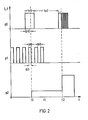
- FIG. 2 shows an example of a modification of the priority sequence when devices are switched off due to the mode of operation of the load computer.
- the abscissa of the diagram in FIG. 2 represents a time axis, the ordinate represents the devices current or device performance.
- the top line shows the power draw of an electrical device with the lowest priority p0
- the middle row shows the power draw of a device with the next higher priority p1
- the bottom line shows the power draw of a device with the higher priority p2.
- the actual power value exceeds the specified power limit.
- the device with the priority p0 would be shutdown in this case regardless of its technical properties and history.
- the operation of the device with priority p0 is continued and instead the device with priority p1 is switched off.
- the load computer C contains information about the time constants or the switch-on and switch-off times te0, te1 or ta0, ta1 that occur in regular two-point operation and, moreover, it can be seen from the recording of the last current flow periods ⁇ tO and ⁇ t1 that the device with the priority p0 is only just beginning has slightly more than half of its on-time required, whereas the device with priority p1 has already been supplied with power for almost its entire on-time, contrary to the priority sequence programmed per se, the least possible impairment for the consumer of electrical energy by switching off the device priority p1 reached.
- the device with priority p1 goes out of operation.
- This device can be, for example, an air conditioning system in cooling mode, the operation of which is superfluous due to cooling in the evening.
- the device with priority p2 starts a very performance-intensive workflow as part of its working cycle, so that the power limit value is exceeded again. In this case maintain the programmed priority sequence, the device with the lowest priority p0 not being switched off but operated with reduced power by being switched on and off periodically at a high clock frequency for the rest of its duty cycle.
Abstract
Description
Die Erfindung betrifft ein System zur Steuerung des elektrischen Energieverbrauchs, vorzugsweise in Haushalten, mit einem Elektrizitätszähler, der ausgangsseitig eine Impulsfolge mit leistungsproportionaler Frequenz an einen Lastrechner abgibt, mit einem Meßperiodengeber und mit den einzelnen energieverbrauchenden Geräten oder Gerätegruppen zugeordneten Schaltgliedern, wobei diese Schaltglieder vom Lastrechner als Ergebnis eines Vergleichs zwischen einem Grenzwert und dem Leistungsistwert für eine Meßperiode nach einer im Lastrechner gespeicherten Prioritätsfolge sowie Geräteleistung beeinflußbar sind.The invention relates to a system for controlling electrical energy consumption, preferably in households, with an electricity meter, which outputs a pulse sequence with power proportional frequency to a load computer on the output side, with a measuring period transmitter and with switching elements assigned to the individual energy-consuming devices or device groups, these switching elements from the load computer can be influenced as a result of a comparison between a limit value and the actual power value for a measuring period according to a priority sequence stored in the load computer and device performance.
Ein derartiges System ist aus der DE-OS 27 08 883 bekannt. Kern des bekannten Systems ist ein elektronischer Maximumwächter, dem Angaben über die Meßperiode und von einem Impulsgeberzähler eine Impulsfolge mit leistungsproportionaler Frequenz zugeführt sind.Dieser Maximumwächter weist einen Computer als Lastrechner und einen nichtflüchtigen Speicher für die Maximumüberwachung und die Einstellung mindestens eines Leistungsgrenzwertes und die Steuerung von Geräten über Schaltglieder auf. Die Prioritäten für die Ab- und Einschaltreihenfolge der Geräte sind hierbei im Lastrechner programmiert. Während jeder Meßperiode errechnet der Lastrechner aus der bereits verbrauchten Energie und der jeweiligen Augenblicksleistung, ob Geräte abzuschalten sind oder noch zugeschaltet werden können. Als zusätzliche Information ist im Speicher die Leistung der einzelnen Geräte abgelegt. Diese wird durch den Lastrechner aus der Änderung der augenblicklichen Gesamtleistung bei Zu- und Abschalten der einzelnen Geräte ermittelt. Aus diesen Leisiungswerten und den programmierten Prioritäten ermittelt der Lastrechner selbsttätig die günstigste Ab-und Zuschaltuigder einzelnen Geräte. Dieses System bietet gegenüber der zentral durch die Elektrizitätsversorgungsunternehmen über Rundsteuerempfänger ausgelösten Ab- bzw. Zuschaltung leistungsintensiver Geräte einen höheren Komfort, da der Abnehmer elektrischer Energie selbst für die einzelnen Geräte die Prioritätsrangfolge vorgeben kann. Diese Prioritätsrangfolge wird jedoch zusätzlich durch die Einbeziehung der Leistung der einzelnen Geräte in den Entscheidungsprozeß über die Ab- bzw. Zuschaltung modifiziert. Dies kann dazu führen, daß die vom Abnehmer elektrischer Energie gewünschte Prioritätsfolge unter Berücksichtigung der Geräteleistung bei der Ab- bzw. Zuschaltung der Geräte außer Kraft gesetzt wird, so daß immer noch die Bedürfnisse des Abnehmers elektrischer Energie zu wenig berücksichtigende Schalthandlungen auftreten können.Such a system is known from DE-OS 27 08 883. At the heart of the known system is an electronic maximum monitor, to which information about the measurement period and a pulse train with a power-proportional frequency are fed. This maximum monitor has a computer as a load computer and a non-volatile memory for maximum monitoring and the setting of at least one power limit value and the control of Devices via switching elements. The priorities for switching the devices off and on are programmed in the load computer. During each measurement period, the load computer uses the energy already used and the instantaneous power to calculate whether devices are to be switched off or can still be switched on. The performance of the individual devices is stored in the memory as additional information. This is determined by the load computer from the change in the instantaneous total power when the individual devices are switched on and off. From these Performance values and the programmed priorities, the load computer automatically determines the cheapest switching on and off of the individual devices. This system offers greater convenience compared to the switching off or switching on of power-intensive devices triggered centrally by the electricity supply companies via ripple control receivers, since the consumer of electrical energy can specify the priority order even for the individual devices. However, this priority ranking is additionally modified by including the performance of the individual devices in the decision-making process regarding the disconnection or connection. This can lead to the priority sequence desired by the consumer of electrical energy being overridden, taking into account the device power when switching the devices on or off, so that switching operations which do not take sufficient account of the needs of the consumer of electrical energy can still occur.
Der Erfindung liegt die Aufgabe zugrunde, ein System der eingangs genannten Art dahingehend zu verbessern, daß eine benutzerfreundlichere Modifikation der Prioritätsfolge bei derAb- bzw. Zuschaltung von Geräten bzw. Gerätegruppen erfolgt.The invention has for its object to improve a system of the type mentioned in such a way that a more user-friendly modification of the priority sequence takes place when switching devices on or on.
Die Aufgabe wird erfindungsgemäß dadurch gelöst, daß der Lastrechner zusätzlich einen nichtflüchtigen Speicher aufweist, in dem die Zeitkonstanten der einzelnen Geräte oder Gerätegruppen abgelegt sind, daß jedes Gerät oder jede Gerätegruppe einen Stromsensor für den zum Gerät bzw. der Gerätegruppe fließenden Strom aufweist, dessen Ausgangssignal dem Lastrechner zugeführt ist, und daß bei Betätigung der Schaltglieder durch den Lastrechner die Zeitkonstanten des Gerätes bzw. der Gerätegruppe und die bisherigen Stromflußdauern berücksichtigt werden. Damit kann der elektrische Energieverbrauch eines Abnehmers vergleichmäßigt oder reduziert werden, wobei die programmierte Prioritätsfolge lediglich einen allgemeinen Rahmen für die Abschaltung und Zuschaltung der einzelnen Geräte oder Gerätegruppen bietet, der jedoch so abwandelbar ist, daß er für den Abnehmer elektrischer Energie mit der geringstmöglichen Beeinträchtigung verbunden ist. Wenn also beispielsweise für einen Heißwasserspeicher die niederwertigste Priorität gespeichert ist und in der Prioritätsfolge einem Gefrierschrank die nächsthöhere Priorität zugeordnet ist, dann wird nicht in allen Fällen, wenn der Leistungsistwert des Abnehmers den Grenzwert erreicht, der Heißwasserspeicher zuerst abgeschaltet, während der Gefrierschrank zunächst, wenn der Grenzwert nach Abschaltung des Heißwasserspeichers unterschritten bleibt, weiter betrieben werden würde. Wenn sich nämlich aufgrund der Zeitkonstanten und der bis zur Abschaltentscheidung verstrichenen Stromflußdauer ergibt, daß der Gefrierschrank nahezu seine untere Grenztemperatur erreicht hat, während der Heißwasserspeicher erst zu Beginn eines Aufheizzyklus steht, dann wird entgegen der an sich programmierten Prioritätsfolge der Gefrierschrank abgeschaltet, wohingegen der Heißwasserspeicher weiter aufgeheizt wird. Ganz analog wird durch den Lastrechner unter Berücksichtigung der Priorität, der Zeitkonstanten und der bisherigen Abschaltdauer die Zuschaltung von Geräten bzw. Gerätegruppen bestimmt. Damit wird für den Abnehmer elektrischer Energie durch die Abschaltung bzw. eine die Prioritätsfolge in Abhängigkeit von der Zeitkonstante und der bisherigen Abschaltdauer modifizierende Zuschaltung die geringstmögliche Beeinträchtigung des Nutzens seiner Geräte bzw. Gerätegruppen erreicht. Das Entscheidende ist also hierbei die Modifikation der programmierten Prioritätsfolge durch Einbeziehung der Vorgeschichte und der sich auf den Komfort des Abnehmers elektrischer Energie auswirkenden technischen Eigenschaften der Geräte bzw. Gerätegruppen zu einer die notwendigen Ab- und Zuschaltungen bestimmenden selbstadaptierenden Prioritätsfolge. Ein solches System kann beispielsweise für die einzelnen Geräte innerhalb einer Wohnung oder für ganze Gruppen von Geräten mit gleicher Zeitkonstante und vergleichbarer Stromflußdauer, beispielsweise innerhalb eines Hochhauses, eingesetzt sein. Unter Zeitkonstante wird hierbei bei temperaturgesteuerten Geräten, wie beispielsweise Kühlschränken, Gefrierschränken, Speicheröfen, Heißwasserspeichern, Elektroöfen, Nachtspeicheröfen, Klimaanlagen, die die thermische Trägheit beim Aufheizen bzw. Abkühlen des Gerätes bzw. des vom Gerät thermisch zu beeinflußenden Mediums bestimmende physikalische Größe verstanden. Bei nichttemperaturgesteuerten Geräten, beispielsweise einer Förderpumpe, die einen bestimmten Wasservorrat in einem Wasserspeicher bereitstellen soll, würde die "Zeitkonstante" beispielsweise aus dem vorhandenen Wasservorrat und der mittleren Entnahmemenge pro Zeiteinheit zu bestimmen sein.The object is achieved in that the load computer additionally has a non-volatile memory in which the time constants of the individual devices or device groups are stored, that each device or each device group has a current sensor for the current flowing to the device or device group, its output signal is fed to the load computer, and that when the switching elements are actuated by the load computer, the time constants of the device or the device group and the previous current flow times are taken into account. This can make the electrical energy consumption of a customer more even or reduced adorned, the programmed priority sequence only offers a general framework for switching off and switching on the individual devices or groups of devices, but which is so variable that it is associated with the least possible impairment for the consumer of electrical energy. If, for example, the lowest priority is saved for a hot water storage tank and the next higher priority is assigned to a freezer in the priority sequence, the hot water storage tank is not switched off first in all cases when the actual power value of the customer reaches the limit, while the freezer is switched off first if the limit value remains below after switching off the hot water tank, would continue to be operated. If, due to the time constant and the elapsed current flow time until the switch-off decision, it appears that the freezer has almost reached its lower limit temperature while the hot water tank is only at the beginning of a heating cycle, then the freezer is switched off, contrary to the priority sequence programmed per se, whereas the hot water tank is further heated. Similarly, the load computer determines the connection of devices or device groups, taking into account the priority, the time constants and the previous switch-off time. For the consumer of electrical energy, the least possible impairment of the use of his devices or groups of devices is achieved by the shutdown or a connection that modifies the priority sequence depending on the time constant and the previous shutdown time. The decisive factor here is the modification of the programmed priority sequence by incorporating the previous history and the technical properties of the devices or device groups which affect the convenience of the consumer of electrical energy the self-adapting priority sequence determining the necessary disconnections and connections. Such a system can be used, for example, for the individual devices within an apartment or for entire groups of devices with the same time constant and comparable current flow duration, for example within a high-rise building. In this case, time constant is understood in the case of temperature-controlled devices, such as, for example, refrigerators, freezers, storage ovens, hot water tanks, electric ovens, night storage ovens, air conditioning systems, which determine the thermal inertia when heating or cooling the device or the physical quantity determining the medium to be thermally influenced by the device. In the case of non-temperature-controlled devices, for example a feed pump, which is intended to provide a certain water supply in a water reservoir, the "time constant" would have to be determined, for example, from the available water supply and the average withdrawal quantity per unit of time.
In einer bevorzugten Ausführungsform ist für die Übertragung von Signalen vom Elektrizitätsversorgungsunternehmen zum Abnehmen ein Empfänger vorgesehen, der an den Elektrizitätszähler und/oder den Lastrechner angeschlossen ist. Damit können beispielsweise Tarifumschaltungen am Elektrizitätszähler vorgenommen werden, aber auch für den Lastrechner entsprechende Grenzwerte vom EVU her eingestellt werden. Darüber hinaus kann in extremen Fällen an den Lastrechner der Befehl abgegeben werden, eine Notabschaltung, d.h. eine Betätigung aller Schaltglieder zur Gesamtabschaltung aller Geräte bzw. Gerätegruppen vorzunehmen. Damit kann durch das Elektrizitätsversorgungsunternehmen eine Beeinflussung des Systems von außen her vorgenommen werden. Durch die Vorgabe eines sehr niedrigen Grenzwertes für den Lastrechner kann damit eine zu hohe Lastspitze abgebaut werden, wobei durch den Lastrechner immer noch die für den Abnehmer elektrischer Energie am wenigsten lästige Alternative ausgewählt wird.In a preferred embodiment, a receiver is provided for the transmission of signals from the electricity supply company for removal, which is connected to the electricity meter and / or the load computer. For example, tariff changes can be made on the electricity meter, but the utility company can also set corresponding limit values for the load computer. In addition, in extreme cases the command can be given to the load computer to carry out an emergency shutdown, ie actuation of all switching elements for the total shutdown of all devices or device groups. This means that the electricity supply company can influence the system from the outside. By specifying a very low limit value for the load computer, an excessively high load peak can thus be reduced, the load computer still providing for the customer electrical energy least annoying alternative is selected.
Darüber hinaus kann ein Sender für die Übertragung von Systemdaten zum Elektrizitätsversorgungsunternehmen vorgesehen sein. Ein solches Systemdatum kann beispielsweise die aktuelle Leistung darstellen, so daß beim Elektrizitätsversorgungsunternehmen ein differenziertes Bild über die Leistungsanforderung von beispielsweise einerseits Haushaltungen und andererseits Industrieanlagen entsteht. Darüber hinaus können diese Systemdaten auch Aufschluß darüber beim Elektrizitätsversorgungsunternehmen vermitteln, welche Arten von Geräten in einem Haushalt derzeit in Betrieb sind.In addition, a transmitter can be provided for the transmission of system data to the electricity supply company. Such a system date can represent the current output, for example, so that the electricity supply company has a differentiated picture of the performance requirements of, for example, households and industrial plants. In addition, this system data can also provide the electricity supply company with information about the types of equipment currently operating in a household.
Eine vorteilhafte Ausführungsform besteht darin, daß der Lastrechner aufgrund eines am Empfänger bei Netzüberlastung eingehenden Signals entsprechend der vom Lastrechner modifizierten Prioritätsfolge je einen Abschaltbefehl mindestens an einzelne Schaltglieder abgibt, wobei eine manuelle Wiedereinschaltung ausgeschlossen ist. Durch das Ausschließen der an sich möglichen manuellen Wiedereinschaltung einzelner Schaltglieder wird in Notfällen dem Elektrizitätsversorgungsunternehmen die Möglichkeit gegeben, eine vom Abnehmer nicht mehr aufzuhebende Verringerung des elektrischen Energieverbrauchs oder Totalabschaltung der elektrischen Geräte oder Gerätegruppen zu erzwingen.An advantageous embodiment consists in that the load computer, based on a signal arriving at the receiver in the event of a network overload, in accordance with the priority sequence modified by the load computer, issues a switch-off command at least to individual switching elements, manual restart being excluded. By excluding the manual reclosing of individual switching elements, which is possible in emergencies, the electricity supply company is given the opportunity to force a reduction in electrical energy consumption that cannot be eliminated by the customer or total shutdown of the electrical devices or device groups.
Der Lastrechner kann als programmierbarer Rechner mit mehreren Arbeitsprogrammen ausgeführt sein, wobei zumindest das die Abschaltung der Geräte oder Gerätegruppen nach Prioritätsfolge, Zeitkonstante und bisheriger Stromflußdauer bestimmende Programm durch ein am Empfänger eingehendes Signal aktivierbar ist. Damit besteht für das Elektrizitätsversorgungsunternehmen die zusätzliche Möglichkeit, unterschiedliche Arbeitsprogramme für den Lastrechner vorzugeben, was zu einer hohen Flexibilität des Systems führt.The load computer can be designed as a programmable computer with several work programs, at least the program determining the switching off of the devices or device groups according to the priority sequence, time constant and previous current flow duration can be activated by a signal arriving at the receiver. This gives the electricity supply company the additional option of different work pro to specify programs for the load computer, which leads to a high flexibility of the system.
Eine "sanfte" Form der Beeinflussung des Energieverbrauchs wird dadurch erreicht, daß der Elektrizitätszähler tarifumschaltbar ausgeführt ist. Hierbei erfolgt die Tarifumschaltung vorzugsweise durch den Lastrechner.A "gentle" form of influencing energy consumption is achieved in that the electricity meter is designed to be tariff-switchable. The tariff changeover is preferably carried out by the load computer.
In einer alternativen Ausführungsform kann die Tarifumschaltung durch ein vom Elektrizitätsversorgungsunternehmen abgegebenes Signal über den Empfänger am Elektrizitätszähler auslösbar sein. Hierdurch wird das an sich weitgehend autarke System zur Steuerung des Energieverbrauchs der direkten Beeinflussung durch das Elektrizitätsversorgungsunternehmen zugänglich.In an alternative embodiment, the tariff changeover can be triggered by a signal emitted by the electricity supply company via the receiver on the electricity meter. This makes the largely self-sufficient system for controlling energy consumption accessible to direct influence by the electricity supply company.
Es ist vorteilhaft, daß Elektrizitätszähler und Lastrechner als integrierte Baueinheit ausgeführt sind. In einer noch weiter gehenden Integrationsstufe können Sender, Empfänger, Lastrechner und Elektrizitätszähler als integrierte Baueinheit ausgeführt sein. Dies gestattet eine überaus kompakte Bauform und ermöglicht darüber hinaus die Doppelnutzung von Komponenten, also beispielsweise von Anzeigeeinheiten, Speichern oder auch des vorzugsweise als Mikrocomputer ausgeführten Lastrechners, der zusätzliche Aufgaben dieser Geräte übernehmen kann.It is advantageous that the electricity meter and load computer are designed as an integrated unit. In an even further integration stage, the transmitter, receiver, load computer and electricity meter can be designed as an integrated unit. This allows an extremely compact design and also enables the double use of components, for example display units, memories or the load computer, which is preferably designed as a microcomputer and can take on additional tasks for these devices.
Als Übertragungsweg zwischen Elektrizitätsversorgungsunternehmen und Empfängerkann das elektrische Versorgungsnetz dienen. In gleicher Weise kann als Übertragungsweg zwischen Sender und EVU dea elektrische Versorgungsnetz dienen. Gegenüber einer Übertragung durch elektromagnetische Wellen ist hierbei sichergestellt, daß ohne den Einsatz von den Aufwand erhöhenden Antennenanlagen Sender und Empfänger zuverlässig ansprechbar sind.The electrical supply network can serve as a transmission path between the electricity supply company and the receiver. In the same way, the electrical supply network can serve as a transmission path between the transmitter and the power supply company. Compared to transmission by electromagnetic waves, this ensures that the transmitter and receiver can be reliably addressed without the use of antenna systems which increase the expenditure.
Der Grenzwert für den Lastrechner kann fest einprogrammiert sein. In einer größere Flexibilität gestattenden Ausführungsform kann jedoch der Grenzwert für den Lastrechner vom Elektrizitätsversorgungsunternehmen über den Empfänger dem Lastrechner vorgebbar sein.The limit value for the load computer can be permanently programmed. In a more flexible embodiment, however, the limit value for the load computer can be predefined by the electricity supply company via the receiver to the load computer.
In einer vorteilhaften Ausführungsform erfolgt bei einer Überschreitung des Grenzwertes über die Schaltglieder eine Abschaltung von Geräten oder Gerätegruppen für Zeitspannen, die ganzzahlige Vielfache der vom Meßperiodengeber vorgegebenen Meßperiode sind. Damit ist die Wiedereinschaltung der Geräte oder Gerätegruppen ohne die Etablierung eines eigenen Einschaltkriteriums, obwohl dieses eine noch höhere Anpassungsfähigkeit des Systemes gestattet, möglich. Falls nach Wiedereinschaltung immer noch eine Überschreitung des Grenzwertes vorliegt, erfolgt wiederum eine Abschaltung für eine festgelegte Zeit, so daß auch längere Abschaltungen immer als ganzzahlige Vielfache der Meßperiode aufbaubar sind, ohne daß komplizierte Einschaltkriterien benötigt werden.In an advantageous embodiment, if the limit value is exceeded via the switching elements, devices or device groups are switched off for periods of time which are integer multiples of the measuring period specified by the measuring period transmitter. This means that devices or device groups can be switched on again without having to set their own switch-on criteria, although this allows the system to be even more adaptable. If the limit value is still exceeded after re-activation, the unit is switched off again for a specified time, so that longer switch-offs can always be built up as integer multiples of the measuring period without the need for complicated switch-on criteria.
In einer alternativen Ausführungsform können bei Überschreitung des Grenzwertes über die Schaltglieder periodische, im Vergleich zur Meßperiode erheblich kürzere Ein- und Abschaltungen einzelner Geräte oder Gerätegruppen durchgeführt werden, so daß der Betrieb der Geräte oder Gerätegruppen mit verringerter Leistung weitergeführt wird. Damit wird zwar die ans Elektrizitätsversorgungsunternehmen gerichtete Leistungsanforderung verringert, aber der Abnehmer elektrischer Energie kommt immer noch in den Genuß eines Teiles der Wirkung des Gerätes oder der Gerätegruppe. So kann beispielsweise durch getakteten Betrieb einer Klimaanlage ein Teil der gewünschten Kühlwirkung an heißen Sommertagen aufrecht erhalten werden, was für den Betreiber gegenüber einer Totalabschaltung immer noch die komfortablere Alternative ist.In an alternative embodiment, when the limit value is exceeded via the switching elements, periodic switch-on and switch-off of individual devices or device groups, which is considerably shorter compared to the measurement period, can be carried out, so that the operation of the devices or device groups is continued with reduced output. Although this reduces the power requirement addressed to the electricity supply company, the consumer of electrical energy still enjoys part of the effect of the device or group of devices. For example, clocked operation of an air conditioning system can maintain part of the desired cooling effect on hot summer days, which is still the more convenient alternative for the operator compared to a total shutdown.
In einer vorteilhaften Ausführungsform ist der Lastrechner zur Vorausberechnung des zu erwartenden Leistungsmaximums eingerichtet. Durch Vergleich mit dem einzuhaltenden Grenzwert für die elektrische Leistung kann somit frühzeitig ein Engpaß erkannt werden, so daß durch frühzeitige Abschaltungen einzelner Geräte oder Gerätegruppen vergleichsweise niedriger Prioritätsfolge die spätere Abschaltung von Geräten oder Gerätegruppen mit hoher Prioritätsfolge vermieden werden kann.In an advantageous embodiment, the load computer is set up to predict the expected maximum power. A bottleneck can thus be identified at an early stage by comparison with the limit value to be observed for the electrical power, so that the early shutdown of individual devices or device groups with a comparatively low priority sequence can prevent the subsequent shutdown of devices or device groups with a high priority sequence.
Es ist vorteilhaft, wenn jedes Schaltglied bistabiles Verhalten aufweist und durch Signale an mindestens einem Steuereingang in jeden der stabilen Zustände überführbar ist. Damit sind die vom Lastrechner gesteuerten Ab-und Einschaltungen ferngesteuert durchführbar. Zusätzlich kann das Schaltglied auch manuell betätigbar sein. Damit kann das Schaltglied den Geräteschalter direkt ersetzen.It is advantageous if each switching element has bistable behavior and can be converted into each of the stable states by signals at at least one control input. The switch-off and switch-on controlled by the load computer can thus be carried out remotely. In addition, the switching element can also be operated manually. The switching element can thus directly replace the device switch.
Für den Abnehmer elektrischer Energie besteht somit die Möglichkeit, unerwünschte Schalthandlungen des Lastrechners manuell zu korrigieren. Um diese Korrekturmöglichkeit bei einer infolge Netzüberlastung nötig gewordenen Notabschaltung auszuschließen, kann das Schaltglied eine Verriegelungseinrichtung gegen manuelle Wiedereinschaltung aufweisen, die durch ein Signal am Steuereingang aktivierbar ist.The consumer of electrical energy thus has the possibility of manually correcting unwanted switching operations of the load computer. In order to rule out this possibility of correction in the event of an emergency shutdown which has become necessary as a result of a network overload, the switching element can have a locking device against manual restart, which can be activated by a signal at the control input.
Der Sensor für den zum Gerät oder zur Gerätegruppe fließenden Strom kann im Schaltglied angeordnet sein. Da ohnehin jedes Gerät oder jede Gerätegruppe über ein Schaltglied an das speisende elektrische Netz angeschlossen ist, ist der Sensor ohne geräteseitige Eingriffe unterbringbar. Darüber hinaus kann das Schaltglied einen Überstromauslöser aufweisen, so daß im Falle einer Überlastung oder eines Kurzschlusses eine schnelle Abschaltung des Gerätes oder der Gerätegruppe möglich ist. Eine vorteilhafte Ausführungsform besteht darin, daß der Spannungsabfall an dem als Sensor genutzten stromdurchflossenen Element des Uberstromauslösers an einem Ausgang des Schaltgliedes für die Rückmeldung zum Lastrechner zur Verfügung steht. Damit ist es nicht erforderlich, einen eigenen Sensor für den zum Gerät oder zur Gerätegruppe fließenden Strom vorzusehen, so daß Bauvolumen und Kosten eingespart werden. Der Überstromauslöser kann als thermischer Auslöser, also beispielsweise als Bimetallkontakt, oder als magnetischer Auslöser ausgebildet sein.The sensor for the current flowing to the device or to the device group can be arranged in the switching element. Since any device or device group is connected to the supplying electrical network via a switching element, the sensor can be accommodated without any intervention on the device side. In addition, the switching element can have an overcurrent release, so that in the event of an overload or a short circuit, the device or the device group can be switched off quickly is. An advantageous embodiment consists in that the voltage drop at the current-carrying element of the overcurrent release used as a sensor is available at an output of the switching element for the feedback to the load computer. It is therefore not necessary to provide a separate sensor for the current flowing to the device or to the device group, so that construction volume and costs are saved. The overcurrent release can be designed as a thermal release, for example as a bimetal contact, or as a magnetic release.
Es ist vorteilhaft, wenn für die Signalübertragung zwischen Lastrechner und Schaltglied eigene Signalleitungen vorgesehen sind. Gegenüber einer Funkübertragung ist dies in Gebäuden der zuverlässigere Übertragungsweg.It is advantageous if separate signal lines are provided for the signal transmission between the load computer and the switching element. Compared to radio transmission, this is the more reliable transmission route in buildings.
Zu übertragen sind hierbei die Schaltbefehle des Lastrechners und das Ausgangssignal des Sensors für den Stromfluß.The switching commands of the load computer and the output signal of the sensor for the current flow are to be transmitted.
Eine alternative Ausführungsform besteht darin, daß für die Signalübertragung zwischen Lastrechner und Schaltglied sowohl dem Lastrechner als auch dem Schaltglied ein Sender-Empfänger-Baustein zugeordnet ist, und daß die Signalübertragung in Form codierter Signale über die Speiseleitungen für die elektrische Energie des Gerätes oder der Gerätegruppe erfolgt. In diesem Fall wird die Installation eigener Signalleitungen eingespart.An alternative embodiment is that for the signal transmission between the load computer and switching element, both the load computer and the switching element, a transmitter-receiver module is assigned, and that the signal transmission in the form of coded signals via the feed lines for the electrical energy of the device or device group he follows. In this case, the installation of own signal lines is saved.
In einer Einfachversion kann als Sensor für den zum Gerät oder zur Gerätegruppe fließenden Strom ein elektrischer Sensor für die Stellung des Schaltgliedes dienen.In a simple version, an electrical sensor for the position of the switching element can serve as a sensor for the current flowing to the device or to the device group.
Damit wird nur Ja/Nein-Aussage gewonnen, was allerdings bei Geräten mit konstanter Leistungsaufnahme keine Probleme aufwirft, da ihr Stromfluß bekannt ist und im nichtflüchtigen Speicher des Lastrechners abgespeichert sein kann.This only gives a yes / no statement, which, however, does not pose any problems for devices with constant power consumption, since their current flow is known and stored in the non-volatile memory of the load computer can be.
In einer alternativen Ausführungsform kann bei Geräten mit während eines Arbeitszyklus unterschiedlicher Leistungsaufnahme dem Sensor ein Grenzwertmelder nachgeschaltet sein, dessen Ausgangssignal nur bei leistungsintensiven Arbeitsabläufen des Arbeitszyklus aktiv ist. Damit werden nur die leistungsintensiven Arbeitsabläufe und zwar in Form einer Ja/Nein-Aussage erfaßt. Beispielsweise bei einer Waschmaschine erfolgt dann nur während des Arbeitsablaufs "Aufheizen" eine Rückmeldung zum Lastrechner, da die restlichen Arbeitsabläufe "Waschvorgang" und "Schleudervorgang" des Arbeitszyklus weniger leistungsintensiv sind.In an alternative embodiment, in the case of devices with different power consumption during a work cycle, a limit detector can be connected downstream of the sensor, the output signal of which is only active during power-intensive work processes of the work cycle. This means that only the performance-intensive work processes are recorded in the form of a yes / no statement. In the case of a washing machine, for example, a feedback to the load computer is then only given during the "heating up" workflow, since the remaining "washing" and "spinning" workflows of the work cycle are less power-intensive.
Durch den Lastrechner kann eine Tarifumschaltung des Elektrizitätszählers auslösbar sein, wenn die Vorausberechnung des zu erwartenden Leistungsmaximum eine Überschreitung des Grenzwertes erwarten läßt. 'Wenn dies zusätzlich durch ein optisches oder akustisches Signal für den Abnehmer elektrischer Energie kenntlich gemacht wird, entsteht damit ein gewisser Kostendruck zur momentanen Verringerung und damit insgesamt zu einer Vergleichmäßigung des Energieverbrauchs.A tariff switchover of the electricity meter can be triggered by the load computer if the prediction of the expected maximum power indicates that the limit value may be exceeded. 'If this is additionally indicated to the consumer of electrical energy by an optical or acoustic signal, this creates a certain cost pressure for the current reduction and thus for a more even energy consumption.
Die Erfindung wird im folgenden anhand eines Ausführungsbeispiels in den Fig. 1 und 2 näher erläutert. Dabei zeigt:
- Fig. 1 ein Blockschaltbild des erfindungsgemäßen Systems und
- Fig. 2 ein Funktionsdiagramm für die Modifikation der programmierten Prioritätsfolge durch den Lastrechner.
- Fig. 1 is a block diagram of the system according to the invention and
- Fig. 2 is a functional diagram for the modification of the programmed priority sequence by the load computer.
In Fig. 1 ist die elektrische Speiseleitung in einem Mehrfamilienwohnhaus mit dem Bezugszeichen 1 belegt.In Fig. 1, the electrical feed line in an apartment building is given the
Von dieser Speiseleitung 1 zweigt die Leitung 2 ab, die der Versorgung einer einzelnen Wohnung des Mehrfamilienwohnhauses mit elektrischer Energie dient. Die Leitung 2 ist an den Elektrizitätszähler Z geführt, der als Impulsgeberzähler ausgebildet ist. Die Leitung 3 nach dem Elektrizitätszähler Z dient der Versorgung der elektrischen Geräte 10 bis 13 in der betreffenden Wohnung. Jedem dieser elektrischen Geräte 10 bis 13 ist ein Schaltglied s0 bis s3 zur Ein- und Abschaltung dieser Geräte vorgeschaltet. Diesen elektrischen Geräten 10 bis 13 sind von dem in dieser Wohnung wohnenden Abnehmer elektrischer Energie die Prioritätswerte p0 bis p3 zugeordnet. Dabei ist dem Gerät 10 die niederwertigste Priorität p0 zugeordnet, dem Gerät 13 die höchstwertige Priorität p3. Diese Prioritäten p0 bis p3 legen einen Rahmen für die vom Abnehmer als tolerabel empfundene Abschaltreihenfolge der elektrischen Geräte derart fest, daß das dem Abnehmer am unwichtigsten erscheinende Gerät die niederwertigste Priorität p0 und dem am wenigsten verzichtbar empfundenen Gerät 13 die höchste Priorität p3 zugeordnet ist. Als Gerät niedrigwertigster Priorität kommt beispielsweise ein Heißwasserspeicher infrage, als "Gerät" höchster Priorität kann beispielsweise die elektrische Beleuchtung oder die Speisung des Fernsehgerätes angesehen werden.From this
Das System zur Steuerung des elektrischen Energieverbrauches in dieser Wohnung umfaßt neben dem Elektrizitätszähler Z sowie den Schaltgliedern s0 bis s3 noch eine der Zweiwegekommunikation zwischen den Elektrizitätsversorgungsunternehmen und dem einzelnen Haushalt dienende Sender-Empfänger-Einheit T, die über die Leitung 4 Information in Form von Daten und Befehlen aus der Leitung 2 empfängt bzw. über die Leitung 5 an die Leitung 2 abgibt und damit zum Elektrizitätsversorgungsunternehmen emittiert. Die zwischen der Sender-Empfänger-Einheit T und dem Elektrizitätsversorgungsunternehmen auszutauschenden Informationen können beispielsweise in Form von aus der Rundsteuertechnik bekannten Impulsbildern codiert sein. Als vom Elektrizitätsversorgungsunternehmen zu den einzelnen Sender-Empfänger-Einheiten zu übertragende Informationen können beispielsweise Adressen der einzelnen Wohnunge, Tarifumschaltbefehle ---für die Umschaltung auf Hochtarif bzw. Niedertarif für als Zweitarifzähler ausgebildete Elektrizitätszähler unterschiedliche Leistungsgrenzwerte für den momentan zulässigen maximalen Energieverbrauch einer Wohnung oder Notabschaltbefehle für bestimmte Geräte, Gerätegruppen oder alle Geräte einer Wohnung sowie Befehle zur Aktivierung einzelner in einem Lastrechner C abgelegter Programme angesehen werden. Als vom Abnehmer elektrischer Energie über die Sender-Empfänger-Einheit an das Elektrizitätsversorgungsunternehmen zu liefernde Daten kämen beispielsweise Adressen der einzelnen Wohnungen, momentane Leistungsdaten, Zählerstände oder sonstige Zustandsdaten bezüglich der in der Wohnung aktiven elektrischen Geräte in Frage. Die Übertragung des Zählerstandes für Zwecke der Tariffernablesung erfolgt vom Elektrizitätszähler Z über die Leitung 6 zur Sender-Empfänger-Einheit T, wo er nach Codierung über die Leitung 5 an das speisende elektrische Netz abgegeben wird. Von der Sender-Empfänger-Einheit T empfangene Tarifumschaltbefehle werden über die Leitung 7 an den Elektrizitätszähler Z übermittelt. Alle anderen Informationen werden vorzugsweise über die Sender-Empfänger-Einheit T zum Lastrechner C oder vom Lastrechner C über die Leitungen 8 und 9 übertragen. Der Lastrechner C ist vorzugsweise als Mikrocomputer mit den zugehörigen Funktionseinheiten, wie Taktgeber, flüchtige und nichtflüchtige Speicher, Programmspeicher, Zentraleinheit, ausgebildet. Dieser Lastrechner hat wesentliche Funktionen eines weitgehend autarken Maximumwächters, dem über den Meßperiodeneingang MP Informationen über die Dauer der Meßperiode sowie über die Leitung 10 die von dem als Impulsgeberzähler ausgebildete Elektrizitätszähler Z eine Impulsfolge mit leistungsproportionaler Frequenz zugeführt sind. Der Informationsübertragung zwischen dem Lastrechner C und dem Elektrizitätszähler Z dient die Leitung 11, über die beispielsweise vom Lastrechner C ermittelte Tarifumschaltbefehle übertragen werden können.The system for controlling the electrical energy consumption in this apartment includes, in addition to the electricity meter Z and the switching elements s0 to s3, one of the two-way communication between the electricity supply company and the individual household, the transceiver unit T, which provides line 4 information in the form of data and receives commands from
Der Lastrechner C ermittelt für die einzelnen Meßperioden aus der über die Leitung 10 eingehenden Impulsfolge mit leistungsproportionaler Frequenz den entsprechenden Leistungsistwert und vergleicht diesen mit mindestens einem im Lastrechner vorhandenen Leistungsistwert. Dieser mindestens eine Leistungsistwert kann entweder fest einprogrammiert sein oder je nach dem Ergebnis einer Bilanz zwischen der zur Verfügung stehenden Leistung und der geforderten Leistung beim Elektrizitätsversorgungsunternehmen durch dieses über die Sender-Empfänger-Einheit T dem Lastrechner C zur Verfügung gestellt werden. In einem nichtflüchtigen Speicher des Lastrechners C stehen darüber hinaus die den einzelnen Geräten 10 bis 13 vom Abnehmer elektrischer Energie diesen Geräten zugeordneten Prioritäten in einer Prioritätsfolge sowie Informationen über die spezifischen Eigenschaften der Geräte in Form des das zeitliche Verhalten dieser Geräte im Bezug auf Ab- bzw. Einschaltungen widerspiegelnden Zeitkonstanten zur Verfügung. Zusätzlich erhält der Lastrechner C aktuelle Betriebsdaten der einzelnen Geräte 10 bis 13 über die Leitungen 12 bis 15 in Form der zu den Geräten 10 bis 13 fließenden Ströme bzw. des Schaltzustandes der zugehörigen Schaltglieder s0 bis s3.The load computer C determines the corresponding actual power value for the individual measuring periods from the pulse sequence coming in via
Der Lastrechner C kann zur Vorausberechnung des während jeder aktuellen Meßperiode zu erwartenden Leistungsmaximums aufgrund des vom Elektrizitätszähler Z in Form der Impulsfolge mit leistungsproportionaler Frequenz gelieferten Leistungsistwertes eingerichtet sein. In diese Vorausberechnung kann auch das unter der Wirkung einer häufig eingesetzten autarken Zweipunktregelung einzelner elektrischer Geräte zu erwartende Schaltverhalten einbezogen sein. Bei tatsächlicher oder aufgrund der Vorausberechnung zu erwartender Annäherung an den dem Lastrechner vorgegebenen Leistungsgrenzwert ermittelt dieser aus der vorgegebenen Prioritätsfolge,"den Zeitkonstanten der einzelnen im Betrieb befindlichen Geräte und der bisherigen Stromflußdauer in diesen einzelnen Geräten, die den Abnehmer elektrischer Energie am wenigsten beeinträchtigende Abschaltung und Abschaltdauer für die einzelnen Geräte. Damit legt der Lastrechner C die für den betreffenden Abnehmer elektrischer Energie in weitgehender Autarkie von Eingriffen des Elektrizitätsversorgungsunternehmens die den einzelnen Abnehmer am wenigsten beeinträchtigende Abschaltung einzelner Geräte fest, wenn dies aufgrund einer erforderlichen Leistungsbegrenzung nötig erscheint. Allerdings hat das Elektrizitätsversorgungsunternehmen sinnvolle Eingriffsmöglichkeiten, beispielsweise durch die Vorgabe von Leistungsgrenzwerten oder die Aktivierung einzelner den Leistunisverbrauch mässigender Programme im Lastrechner. Zusätzlich kann das Elektrizitätsversorgungsunternehmen einen Befehl zur Notabschaltung übertragen, dessen Ausführung durch den Lastrechner C erfolgt. Dieser Befehl kann so geartet sein, daß entweder eine Abschaltung aller Geräte veranlaßt wird oder eine Abschaltung von Geräten bis zu einer bestimmten Prioritätsstufe.The load computer C can be set up to pre-calculate the power maximum to be expected during each current measuring period on the basis of the power actual value supplied by the electricity meter Z in the form of the pulse train with a power proportional frequency. In the This advance calculation can also include the switching behavior to be expected under the effect of a frequently used self-sufficient two-point control of individual electrical devices. In the event of an actual or anticipated approximation to the power limit given to the load computer, the latter determines from the given priority sequence, "the time constants of the individual devices in operation and the current current flow duration in these individual devices, which shuts down the consumer of electrical energy least and The load computer C thus determines the shutdown of individual devices that is least detrimental to the individual consumer for the relevant consumer of electrical energy in a largely self-sufficient manner from interventions by the electricity supply company, if this appears necessary due to a required power limitation. However, the electricity supply company Useful intervention options, for example by specifying performance limit values or activating individual programs that moderate performance consumption i m load computer. In addition, the electricity supply company can transmit an emergency shutdown command, which is executed by the load computer C. This command can be of the type that either switches off all devices or switches off devices up to a certain priority level.
Die Schaltglieder s0 bis s3 weisen bistabiles Verhalten auf und sind sowohl manuell betätigbar als auch durch elektrische Signale an mindestens einem Steuereingang in jeden ihrer beiden stabilen Zustände schaltbar. Diese die Schalthandlung herbeiführenden Signale werden im Lastrechner C erzeugt und über die Leitungen 16 bis 19 auf die Schaltglieder übertragen. Die Leitungen 16 bis 19 zwischen dem Lastrechner C und den Schaltgliedern s0 bis s3 erfordern einen gewissen Installationsaufwand. Dieser ist vermeidbar, wenn zur Übertragung der die Schalthandlungen der Schaltglieder auslösenden Signale das installierte elektrische Netz, also die Leitung 3 benutzt wird. In diesem Fall werden die den einzelnen SchaltgliedemsO bis s3 zugeordneten Signale zur Durchführung von Schalthandlungen nach entsprechender Codierung direkt auf die Leitung 3 übertragen, so daß sie von den einzelnen Schaltglieder s0 bis s3 zugeordneten Empfängern erkannt und zur Auslösung der Schalthandlung an das entsprechende Schaltglied weitergegeben werden können. Hierbei kann man sich ähnlicher Verfahren wie bei der Rundsteuertechnik bedienen. Die Schaltbefehle können demnach beispielsweise nach dem Impulsabstandsverfahren oder nach dem Impulsmusterverfahren übertragen werden. Die entsprechende Codierung kann durch den Lastrechner mit übernommen werden. Für den Fall der Notabschaltung ist jedes Schaltglied mit einer Verriegelungseinrichtung versehen, die eine manuelle Wiedereinschaltung ausschließt und die durch ein entsprechendes Steuersignal aktivierbar ist. Dies kann dadurch realisiert sein, daß jedes der Schaltglieder s0 bis s3 eine die Abschaltung bewirkende Auslösespule enthält, die im Fall der Notabschaltung eine Dauererregung erhält. Zur Erfassung des zu den Geräten 10 bis 13 fließenden Stromes ist in jedem der Schaltglieder s0 bis s3 ein Sensor 20 bis 23 vorgesehen. Darüber hinaus kann in jedes der Schaltglieder s0 bis s3 zum Schutz gegen Überlastung ein Überstromauslöser eingebaut sein. Dies bietet die Möglichkeit, daß das stromdurchflossene Element des Überstromauslösers gleichzeitig als Sensor des zum zugehörigen Gerät 10 bis 13 fließenden Stromes genutzt wird, indem der an diesem Element auftretende Spannungsabfall über die Leitungen 12 bis 15 zum Lastrechner C zurückgemeldet wird. Bei Geräten, die im Einschaltzustand eine konstante Strom- bzw. Leistungsaufnahme aufweisen, ist es ausreichend, als Sensor für den zum Gerät fließenden Strom einen elektrischen Sensor für die Stellung des Schaltgliedes einzusetzen. Die Information über den konstanten Strom- bzw. Leistungsverbrauch ist in diesem Fall in einem nichtflüchtigen Speicher des Lastrechners abzulegen.The switching elements s0 to s3 exhibit bistable behavior and are both manually operable and switchable in each of their two stable states by means of electrical signals at at least one control input. These signals causing the switching action are generated in the load computer C and transmitted to the switching elements via
Geräte mit nichtkonstanter Leistungsaufnahme sind solche, die einen komplizierten Arbeitszyklus mit verschiedenen Arbeitsabläufen aufweisen, also beispielsweise Waschmaschinen. In diesem Fall genügt es, nur die leistungsintensiven Arbeitsabläufe an den Lastrechner C zurückzumelden. In diesem Fall ist dem Sensor für den zum Gerät fließenden Strom ein Grenzwertmelder nachzuschalten, dessen Ausgangssignal nur bei leistungsintensiven Arbeitsabläufen des Arbeitszyklus aktiv ist.Devices with non-constant power consumption are those that have a complicated work cycle with different work processes, for example washing machines. In this case, it is sufficient to report back only the power-intensive work processes to the load computer C. In this case, the sensor for the current flowing to the device is to be followed by a limit indicator, the output signal of which is only active during high-power workflows of the work cycle.
Die vom Lastrechner C über die Leitung 11 veranlaßte Tarifumschaltung des Elektrizitätszählers Z kann bei einem zur Vorausberechnung des zu erwartenden Leistungsmaximums eingerichteten Lastrechner dann ausgelöst werden, wenn die Vorausberechnung des zu erwartenden Leistungsmaximums eine Überschreitung des Grenzwertes erwarten läßt. Der Elektrizitätszähler Z und der Lastrechner können als integrierte Baueinheit ausgeführt sein. In diese integrierte Baueinheit kann auch zusätzlich die Sender-Empfänger-Einheit T einbezogen sein. Bei einem unter Einsatz eines Mikrocomputers aufgebauten Lastrechner C kann der Mikrocomputer Funktionen des Elektrizitätszählers Z sowie der Sender-Empfänger-Einheit T mit übernehmen. Dies ist durch die strichpunktierte Umrandung der Blöcke C, Z, T angedeutet.The tariff changeover of the electricity meter Z initiated by the load computer C via the
In Fig. 2 ist ein Beispiel für eine aufgrund der Arbeitsweise des Lastrechners erfolgende Modifizierung der Prioritätsfolge beim Abschalten von Geräten veranschaulicht. Die Abszisse des Diagramms in Fig. 2 stellt eine Zeitachse dar, die Ordinate repräsentiert den Gerätestrom bzw. die Geräteleistung. In der obersten Zeile ist die Leistungsentnahme eines elektrischen Gerätes mit der niederwertigsten Priorität p0 in der mittleren Zeile die Leistungsentnahme eines Gerätes mit der nächsthöheren Priorität p1 und in der unteren Zeile die Leistungsentnahme eines Gerätes mit der wiederum höheren Priorität p2 dargestellt. Im Zeitpunkt t0 überschreitet der Leistungsistwert den vorgegebenen Leistungsgrenzwert. Bei einer rein prioritätsgesteuerten Abschaltung durch den Lastrechner C würde in diesem Fall das Gerät mit der Priorität p0 unabhängig von dessen technischen Eigenschaften und Vorgeschichte abgeschaltet werden. Bei dem erfindungsgemäßen Lastrechner wird jedoch der Betrieb des Gerätes mit der Priorität p0 weitergeführt und stattdessen das Gerät mit der Priorität p1 abgeschaltet. Da im Lastrechner C Informationen über die Zeitkonstanten oder die im regulären Zweipunktbetrieb auftretenden Ein- und Abschaltzeiten te0, te1 bzw. ta0, ta1 vorhanden sind und darüber hinaus aus der Erfassung der letzten Stromflußdauern ΔtO undÄt1 hervorgeht, daß das Gerät mit der Priorität p0 gerade erst etwas mehr als die Hälfte seiner an sich notwendigen Einschaltdauer aufweist, wohingegen das Gerät mit der Priorität p1 bereits fast für seine gesamte Einschaltdauer mit Strom versorgt wurde, wird entgegen der an sich programmierten Prioritätsfolge die geringstmögliche Beeinträchtigung für den Abnehmer elektrischer Energie durch Abschaltung des Gerätes mit der Priorität p1 erreicht.FIG. 2 shows an example of a modification of the priority sequence when devices are switched off due to the mode of operation of the load computer. The abscissa of the diagram in FIG. 2 represents a time axis, the ordinate represents the devices current or device performance. The top line shows the power draw of an electrical device with the lowest priority p0, the middle row shows the power draw of a device with the next higher priority p1 and the bottom line shows the power draw of a device with the higher priority p2. At time t0, the actual power value exceeds the specified power limit. In the case of a purely priority-controlled shutdown by the load computer C, the device with the priority p0 would be shutdown in this case regardless of its technical properties and history. In the load computer according to the invention, however, the operation of the device with priority p0 is continued and instead the device with priority p1 is switched off. Since the load computer C contains information about the time constants or the switch-on and switch-off times te0, te1 or ta0, ta1 that occur in regular two-point operation and, moreover, it can be seen from the recording of the last current flow periods ΔtO and Ät1 that the device with the priority p0 is only just beginning has slightly more than half of its on-time required, whereas the device with priority p1 has already been supplied with power for almost its entire on-time, contrary to the priority sequence programmed per se, the least possible impairment for the consumer of electrical energy by switching off the device priority p1 reached.
Im Zeitpunkt t1 geht das Gerät mit der Priorität p1 außer Betrieb. Dieses Gerät kann beispielsweise eine Klimaanlage im Kühlbetrieb sein, deren Betrieb wegen einer abendlichen Abkühlung überflüssig wird. Im Zeitpunkt t2 beginnt das Gerät mit der Priorität p2 einen sehr leistungsintensiven Arbeitsablauf im Rahmen seines Arbeitszyklus, so daß eine erneute Überschreitung des Leistungsgrenzwertes erfolgt. In diesem Fall wird die programmierte Prioritätsfolge beibehalten, wobei das Gerät mit niedrigster Priorität p0 nicht abgeschaltet, sondern mit verringerter Leistung betrieben wird, indem es periodisch mit hoher Taktfrequenz für den Rest seiner Einschaltdauer ein- und ausgeschaltet wird.At time t1, the device with priority p1 goes out of operation. This device can be, for example, an air conditioning system in cooling mode, the operation of which is superfluous due to cooling in the evening. At time t2, the device with priority p2 starts a very performance-intensive workflow as part of its working cycle, so that the power limit value is exceeded again. In this case maintain the programmed priority sequence, the device with the lowest priority p0 not being switched off but operated with reduced power by being switched on and off periodically at a high clock frequency for the rest of its duty cycle.
Claims (27)
Priority Applications (1)
| Application Number | Priority Date | Filing Date | Title |
|---|---|---|---|
| AT83106516T ATE44417T1 (en) | 1982-07-15 | 1983-07-04 | SYSTEM FOR CONTROLLING ELECTRICAL ENERGY CONSUMPTION, PREFERABLE IN HOUSEHOLDS. |
Applications Claiming Priority (2)
| Application Number | Priority Date | Filing Date | Title |
|---|---|---|---|
| DE3226544 | 1982-07-15 | ||
| DE19823226544 DE3226544A1 (en) | 1982-07-15 | 1982-07-15 | SYSTEM FOR CONTROLLING THE ELECTRICAL ENERGY CONSUMPTION, PREFERABLY IN HOUSEHOLD |
Publications (3)
| Publication Number | Publication Date |
|---|---|
| EP0099043A2 true EP0099043A2 (en) | 1984-01-25 |
| EP0099043A3 EP0099043A3 (en) | 1986-05-14 |
| EP0099043B1 EP0099043B1 (en) | 1989-07-05 |
Family
ID=6168528
Family Applications (1)
| Application Number | Title | Priority Date | Filing Date |
|---|---|---|---|
| EP83106516A Expired EP0099043B1 (en) | 1982-07-15 | 1983-07-04 | System for the control of electric energy consumption, preferably domestic |
Country Status (3)
| Country | Link |
|---|---|
| EP (1) | EP0099043B1 (en) |
| AT (1) | ATE44417T1 (en) |
| DE (2) | DE3226544A1 (en) |
Cited By (8)
| Publication number | Priority date | Publication date | Assignee | Title |
|---|---|---|---|---|
| EP0198222A2 (en) * | 1985-03-12 | 1986-10-22 | Micro Logic Gesellschaft für rechnergesteuerte Systeme mbH | Power distribution method |
| EP0607739A2 (en) * | 1992-12-22 | 1994-07-27 | Niessen S.A. | A management system for electric domestic appliances |
| EP0620631A1 (en) * | 1993-04-15 | 1994-10-19 | ZELTRON S.p.A. | Management system for domestic electric loads |
| EP0660486A1 (en) * | 1993-12-23 | 1995-06-28 | ZELTRON S.p.A. | Improvement in an electric load management arrangement |
| FR2719440A1 (en) * | 1994-04-28 | 1995-11-03 | Delta Dore | Electrical installation control appts. in single dwelling |
| WO1999022286A1 (en) * | 1997-10-24 | 1999-05-06 | Robert Bosch Gmbh | Switching actuator for controlling electrical consumers |
| WO2000059092A1 (en) * | 1999-03-26 | 2000-10-05 | Broemsel Sven | Method and system for determining a quantity of energy required or consumed by a consumer |
| WO2004023624A1 (en) * | 2002-09-05 | 2004-03-18 | Dynagen Technologies Inc. | System and method for power load management |
Families Citing this family (9)
| Publication number | Priority date | Publication date | Assignee | Title |
|---|---|---|---|---|
| DE4019523A1 (en) * | 1990-06-19 | 1992-01-09 | Decher Dieter | ARRANGEMENT FOR CONTROLLING THE POWER CONSUMPTION OF A CUSTOMER |
| DE4023846C2 (en) * | 1990-07-27 | 1998-09-10 | Aeg Hausgeraete Gmbh | Control unit for a washing machine and a tumble dryer |
| DE4109928C2 (en) * | 1991-03-26 | 1998-02-26 | Muenster Stadtwerke | Device for measuring the power consumption of a plurality of electrical consumption units |
| DE29714767U1 (en) * | 1997-08-18 | 1999-01-21 | Siemens Ag | Network control arrangement |
| DE19827345B4 (en) * | 1998-06-19 | 2005-04-14 | Fünfgeld, Christian, Dipl.-Ing. | Method for deriving the active power of electrical consumers |
| DE10009325A1 (en) * | 2000-02-22 | 2001-08-23 | Deutsche Telekom Ag | Monitoring power balance in power supply network by transmitting changes in power values to nearest switching centre and forwarding to control center as required |
| DE102004002189A1 (en) * | 2004-01-16 | 2005-08-04 | EMH Elektrizitätszähler GmbH & Co. KG | Electronic electricity meter or ripple control receiver for electricity meters |
| DE102004053709A1 (en) * | 2004-11-03 | 2006-05-04 | Schneck, Katrin, Dr. | Remote control device for electrical power consumer e.g. for street lights, includes communication module with transmission section |
| DE102005020519B4 (en) * | 2005-04-29 | 2009-03-12 | Miele & Cie. Kg | Domestic appliance with a control device and method for operating a household appliance |
Citations (5)
| Publication number | Priority date | Publication date | Assignee | Title |
|---|---|---|---|---|
| US3906242A (en) * | 1974-08-16 | 1975-09-16 | Megatherm Corp | Computerized peak-shaving system for alleviating electric utility peak loads |
| DE2708883A1 (en) * | 1977-02-25 | 1978-08-31 | Heliowatt Werke | Electronic max. monitor with intelligible indication - operates without intermediate conversion using computer and non-volatile store |
| US4181950A (en) * | 1977-09-30 | 1980-01-01 | Westinghouse Electric Corp. | Adaptive priority determination power demand control method |
| EP0015666A1 (en) * | 1979-02-21 | 1980-09-17 | South Eastern Electricity Board | Apparatus for controlling electrical power consumption |
| GB2075285A (en) * | 1980-04-28 | 1981-11-11 | Honeywell Inc | Load management control system |
-
1982
- 1982-07-15 DE DE19823226544 patent/DE3226544A1/en not_active Withdrawn
-
1983
- 1983-07-04 EP EP83106516A patent/EP0099043B1/en not_active Expired
- 1983-07-04 AT AT83106516T patent/ATE44417T1/en not_active IP Right Cessation
- 1983-07-04 DE DE8383106516T patent/DE3380147D1/en not_active Expired
Patent Citations (5)
| Publication number | Priority date | Publication date | Assignee | Title |
|---|---|---|---|---|
| US3906242A (en) * | 1974-08-16 | 1975-09-16 | Megatherm Corp | Computerized peak-shaving system for alleviating electric utility peak loads |
| DE2708883A1 (en) * | 1977-02-25 | 1978-08-31 | Heliowatt Werke | Electronic max. monitor with intelligible indication - operates without intermediate conversion using computer and non-volatile store |
| US4181950A (en) * | 1977-09-30 | 1980-01-01 | Westinghouse Electric Corp. | Adaptive priority determination power demand control method |
| EP0015666A1 (en) * | 1979-02-21 | 1980-09-17 | South Eastern Electricity Board | Apparatus for controlling electrical power consumption |
| GB2075285A (en) * | 1980-04-28 | 1981-11-11 | Honeywell Inc | Load management control system |
Cited By (10)
| Publication number | Priority date | Publication date | Assignee | Title |
|---|---|---|---|---|
| EP0198222A2 (en) * | 1985-03-12 | 1986-10-22 | Micro Logic Gesellschaft für rechnergesteuerte Systeme mbH | Power distribution method |
| EP0198222A3 (en) * | 1985-03-12 | 1988-08-31 | Micro Logic Gesellschaft für rechnergesteuerte Systeme mbH | Power distribution method |
| EP0607739A2 (en) * | 1992-12-22 | 1994-07-27 | Niessen S.A. | A management system for electric domestic appliances |
| EP0607739A3 (en) * | 1992-12-22 | 1995-08-02 | Niessen Sa | A management system for electric domestic appliances. |
| EP0620631A1 (en) * | 1993-04-15 | 1994-10-19 | ZELTRON S.p.A. | Management system for domestic electric loads |
| EP0660486A1 (en) * | 1993-12-23 | 1995-06-28 | ZELTRON S.p.A. | Improvement in an electric load management arrangement |
| FR2719440A1 (en) * | 1994-04-28 | 1995-11-03 | Delta Dore | Electrical installation control appts. in single dwelling |
| WO1999022286A1 (en) * | 1997-10-24 | 1999-05-06 | Robert Bosch Gmbh | Switching actuator for controlling electrical consumers |
| WO2000059092A1 (en) * | 1999-03-26 | 2000-10-05 | Broemsel Sven | Method and system for determining a quantity of energy required or consumed by a consumer |
| WO2004023624A1 (en) * | 2002-09-05 | 2004-03-18 | Dynagen Technologies Inc. | System and method for power load management |
Also Published As
| Publication number | Publication date |
|---|---|
| EP0099043B1 (en) | 1989-07-05 |
| DE3380147D1 (en) | 1989-08-10 |
| DE3226544A1 (en) | 1984-01-19 |
| EP0099043A3 (en) | 1986-05-14 |
| ATE44417T1 (en) | 1989-07-15 |
Similar Documents
| Publication | Publication Date | Title |
|---|---|---|
| EP0099043B1 (en) | System for the control of electric energy consumption, preferably domestic | |
| DE69333596T2 (en) | Control system for power distribution | |
| EP2695269B2 (en) | Optimized load management | |
| DE102004029331B4 (en) | System for the central control of an air conditioning system and method for operating the same | |
| DE69632216T2 (en) | Method of power management in a household environment | |
| DE102008057563B4 (en) | Method and device for network-compliant operation of a plurality of decentralized with consumers / generators of electrical energy and connected to a low-voltage electrical network unit | |
| EP2589125A1 (en) | Switching on end devices according to network load | |
| WO2008145170A1 (en) | Method for configuring an automation system | |
| DE112011102128T5 (en) | Electricity management system for efficiently operating a plurality of electric appliances, electric apparatus therefor, central control unit, computer program and storage medium therefor, and methods for managing electric appliances by means of the central control unit | |
| DE19842043B4 (en) | A method for automatically and consumer-oriented minimization of the total power consumption and peak power of a group of individual electrical consumers connected to a power supply network | |
| EP2875560B1 (en) | Method for controlling the ratio between supplied and drawn electric energy in an electric energy supply network | |
| EP2476984B1 (en) | Refrigeration and/or freezer device | |
| DE102007043888B4 (en) | Device for supplying a consumer | |
| EP0268697B1 (en) | Method and system for reducing the peak power of supply and disposal systems using transmission items | |
| DE4432745C1 (en) | Storage heating device control system | |
| EP0464423B1 (en) | Device for controlling the total energy-consumption of an electricity consumer | |
| DE19932833A1 (en) | Regulating total power of power generation system(s) with group of loads involves using load schema enabling more cost-effective utilization of energy tariffs with load time shifts | |
| EP0667968B1 (en) | Method and device for minimizing the energy consumption of an electrical load | |
| EP1072081B1 (en) | Method for adjusting total power of an electric installation, especially of a group of electric consumer | |
| DE102004032618B4 (en) | Solar-powered radio-transmitting temperature sensor, e.g. for use in opening or closing a heating valve, is configured so that it only transmits a change in measured temperature when the change exceeds a threshold value | |
| DE202021002540U1 (en) | Dishwasher with power adjustment to maximize self-consumption with local regenerative power generation | |
| EP2594858A1 (en) | Method and system for remote control of decentralised individual air conditioners without cross-linking interface | |
| DE69933748T2 (en) | Method for controlling the load of at least one heating device, in particular an electric heat accumulator, and / or the thermal capacity of the construction parts and the equipment; Apparatus for carrying out the method | |
| EP2728707A2 (en) | Emergency power supply device | |
| EP2444765B1 (en) | System comprising at least one refrigeration and/or freezer device |
Legal Events
| Date | Code | Title | Description |
|---|---|---|---|
| PUAI | Public reference made under article 153(3) epc to a published international application that has entered the european phase |
Free format text: ORIGINAL CODE: 0009012 |
|
| AK | Designated contracting states |
Designated state(s): AT CH DE GB LI SE |
|
| PUAL | Search report despatched |
Free format text: ORIGINAL CODE: 0009013 |
|
| AK | Designated contracting states |
Kind code of ref document: A3 Designated state(s): AT CH DE GB LI SE |
|
| 17P | Request for examination filed |
Effective date: 19860728 |
|
| 17Q | First examination report despatched |
Effective date: 19880420 |
|
| GRAA | (expected) grant |
Free format text: ORIGINAL CODE: 0009210 |
|
| AK | Designated contracting states |
Kind code of ref document: B1 Designated state(s): AT CH DE GB LI SE |
|
| REF | Corresponds to: |
Ref document number: 44417 Country of ref document: AT Date of ref document: 19890715 Kind code of ref document: T |
|
| REF | Corresponds to: |
Ref document number: 3380147 Country of ref document: DE Date of ref document: 19890810 |
|
| GBT | Gb: translation of ep patent filed (gb section 77(6)(a)/1977) | ||
| PLBE | No opposition filed within time limit |
Free format text: ORIGINAL CODE: 0009261 |
|
| STAA | Information on the status of an ep patent application or granted ep patent |
Free format text: STATUS: NO OPPOSITION FILED WITHIN TIME LIMIT |
|
| 26N | No opposition filed | ||
| EAL | Se: european patent in force in sweden |
Ref document number: 83106516.4 |
|
| PGFP | Annual fee paid to national office [announced via postgrant information from national office to epo] |
Ref country code: GB Payment date: 19960621 Year of fee payment: 14 Ref country code: AT Payment date: 19960621 Year of fee payment: 14 |
|
| PGFP | Annual fee paid to national office [announced via postgrant information from national office to epo] |
Ref country code: SE Payment date: 19960723 Year of fee payment: 14 |
|
| PGFP | Annual fee paid to national office [announced via postgrant information from national office to epo] |
Ref country code: DE Payment date: 19960917 Year of fee payment: 14 |
|
| PGFP | Annual fee paid to national office [announced via postgrant information from national office to epo] |
Ref country code: CH Payment date: 19961017 Year of fee payment: 14 |
|
| PG25 | Lapsed in a contracting state [announced via postgrant information from national office to epo] |
Ref country code: GB Free format text: LAPSE BECAUSE OF NON-PAYMENT OF DUE FEES Effective date: 19970704 Ref country code: AT Free format text: LAPSE BECAUSE OF NON-PAYMENT OF DUE FEES Effective date: 19970704 |
|
| PG25 | Lapsed in a contracting state [announced via postgrant information from national office to epo] |
Ref country code: SE Effective date: 19970705 |
|
| PG25 | Lapsed in a contracting state [announced via postgrant information from national office to epo] |
Ref country code: LI Free format text: LAPSE BECAUSE OF NON-PAYMENT OF DUE FEES Effective date: 19970731 Ref country code: CH Free format text: LAPSE BECAUSE OF NON-PAYMENT OF DUE FEES Effective date: 19970731 |
|
| GBPC | Gb: european patent ceased through non-payment of renewal fee |
Effective date: 19970704 |
|
| REG | Reference to a national code |
Ref country code: CH Ref legal event code: PL |
|
| PG25 | Lapsed in a contracting state [announced via postgrant information from national office to epo] |
Ref country code: DE Free format text: LAPSE BECAUSE OF NON-PAYMENT OF DUE FEES Effective date: 19980401 |
|
| EUG | Se: european patent has lapsed |
Ref document number: 83106516.4 |