EP0099115A2 - Cowling structure for an automotive vehicle - Google Patents
Cowling structure for an automotive vehicle Download PDFInfo
- Publication number
- EP0099115A2 EP0099115A2 EP83106835A EP83106835A EP0099115A2 EP 0099115 A2 EP0099115 A2 EP 0099115A2 EP 83106835 A EP83106835 A EP 83106835A EP 83106835 A EP83106835 A EP 83106835A EP 0099115 A2 EP0099115 A2 EP 0099115A2
- Authority
- EP
- European Patent Office
- Prior art keywords
- cowling
- top panel
- cowl top
- windshield
- box
- Prior art date
- Legal status (The legal status is an assumption and is not a legal conclusion. Google has not performed a legal analysis and makes no representation as to the accuracy of the status listed.)
- Withdrawn
Links
Images


Classifications
-
- B—PERFORMING OPERATIONS; TRANSPORTING
- B62—LAND VEHICLES FOR TRAVELLING OTHERWISE THAN ON RAILS
- B62D—MOTOR VEHICLES; TRAILERS
- B62D25/00—Superstructure or monocoque structure sub-units; Parts or details thereof not otherwise provided for
- B62D25/08—Front or rear portions
- B62D25/081—Cowls
-
- B—PERFORMING OPERATIONS; TRANSPORTING
- B60—VEHICLES IN GENERAL
- B60J—WINDOWS, WINDSCREENS, NON-FIXED ROOFS, DOORS, OR SIMILAR DEVICES FOR VEHICLES; REMOVABLE EXTERNAL PROTECTIVE COVERINGS SPECIALLY ADAPTED FOR VEHICLES
- B60J10/00—Sealing arrangements
- B60J10/30—Sealing arrangements characterised by the fastening means
-
- B—PERFORMING OPERATIONS; TRANSPORTING
- B60—VEHICLES IN GENERAL
- B60J—WINDOWS, WINDSCREENS, NON-FIXED ROOFS, DOORS, OR SIMILAR DEVICES FOR VEHICLES; REMOVABLE EXTERNAL PROTECTIVE COVERINGS SPECIALLY ADAPTED FOR VEHICLES
- B60J10/00—Sealing arrangements
- B60J10/70—Sealing arrangements specially adapted for windows or windscreens
-
- B—PERFORMING OPERATIONS; TRANSPORTING
- B62—LAND VEHICLES FOR TRAVELLING OTHERWISE THAN ON RAILS
- B62D—MOTOR VEHICLES; TRAILERS
- B62D25/00—Superstructure or monocoque structure sub-units; Parts or details thereof not otherwise provided for
- B62D25/08—Front or rear portions
- B62D25/10—Bonnets or lids, e.g. for trucks, tractors, busses, work vehicles
- B62D25/12—Parts or details thereof
Definitions
- the present invention relates generally to a cowling structure for an automotive vehicle, which can be conveniently assembled to a vehicle body and effectively establishes a water-proof seal between a cowl top panel and the bottom portion of the windshield. More specifically, the invention relates to a molding disposed between the lower end of the windshield and the cowl top panel to provide a water-proof seal and a decorative appearance.
- a cowl top panel is secured to a cowling box adjacent the windshield.
- the windshield is bonded to the assembly of the cowling box and the cowl top panel so that an essentially V-shaped groove is formed between the cowl top panel and the lower end of the windshield.
- a water-proofing molding is mounted over the groove to prevent rain water, washer fluid and the like from entering the interior of the cowling box.
- the molding is usually positioned over the groove after the cowling assembly and the windshield are assembled. This required additional process step results in higher assembly costs in manufacturing the vehicle.
- the water-proofing effect of the conventional molding is apt to weaken after a long period of use and permit leakage of water into the interior and rusting of the cowling box.
- Another object of the present invention is to provide a cowling structure having a water-proofing molding preassembled to a cowl top panel detachably attached to a cowling box.
- a cowling structure comprising a cowl top panel detachably connected to a cowl box panel, and a molding on a lateral edge of the cowl top panel adjacent the bottom of the windshield.
- the molding has a tongue portion extending toward the windshield and adapted to establish sealing contact at the ends thereof.
- the molding is made of a synthetic resin and is deformable to permit installation of the windshield onto the cowling assembly.
- a cowling structure comprises a cowling box, a cowl top panel, and an elastic molding attached to the cowl top panel and having a tongue portion extending towards the lower end portion of a windshield to elastically and sealingly contact the windshield in order to establish a water-tight seal therebetween.
- a cowling assembly 10 is provided between an engine hood 12 and a windshield 14 for reinforcing a vehicle body against lateral stress, for introducing ambient air for an air conditioner unit, and for receiving a wiper-and-washer assembly (not shown).
- a cowl top panel 16 is positioned on substantially the same plane as the engine hood to form a substantially smooth upper surface for the vehicle front portion.
- a molding 18 is provided between the cowl top panel 16 and the lower end of the windshield 14, for providing decorative appearance and sealing the cowl top panel to the windshield to rain water, washer fluid and so forth from entering the cowling assembly.
- Figs. 2 to 5 show a detail of. the cowling assembly 10 of Fig. 1.
- the cowling assembly 10 comprises a cowling box 20 and the cowl top panel 16.
- Cowl top panel 16 is formed into essentially thin box-shaped configuration with an upper plane major section 22 and a vertical circumferential wall section 24.
- a substantially L-shaped flange 26 extends from the base of circumferential wall section 24 at the side remote from the windshield 14, to define a water drain groove 28 therewith.
- the horizontal section of the L-shaped flange 26 is formed with a plurality of circular openings 30 which are aligned with circular openings 32 formed in a lateral flange 34 extending from the top of the cowling box front panel 35.
- the cowl top panel 16 has a plurality of strips or tabs 36 extending from the base of circumferential wall section 24 adjacent the windshield 14. On both side portions of circumferential wall section 24 the cowl top panel 16 also has inwardly extending retainer strips 38.
- Cowling box 20 comprises a dash upper panel 40, a cowling box front panel 35 and cowling box side panels 44.
- Front panel 35 has flanges 34 and 46 along the upper and lower edges thereof, respectively.
- Flange 46 is fixedly secured to the horizontal surface 48 of the dash upper panel.
- the side panels 44 each has a substantially vertical major section 50 and a horizontal upper section 52 so that they have an essentially L-shaped configuration.
- the side panel 44 also has flanges 54 and 56 fixed to the horizontal surface 48 and the sloped surface of the dash upper panel 40.
- the side panel 44 is further formed with a hook 45 which is adapted to engage with the retainer strips 38 on cowl top panel 16.
- the dash upper panel 40, a front panel 35 and the side panel define the substantially box form cowling box as assembled with an internal space therein.
- a stiffener 58 is inserted into the internal space of the cowling box 20.
- Stiffener 58 is formed with a flange 60 extending along the lower edge thereof.
- the flange 60 is fixed onto the dash upper panel 40.
- Stiffener 58 substantially follows the slope of windshield 14.
- the upper edge of the stiffener is positioned behind the lower end of the windshield 14 and is bonded onto the rear surface of the windshield with an adhesive 62.
- An upper flange 64 of the dash upper panel 40 is secured to the upper end of the stiffener.
- Stiffener 58 is formed with a plurality of elongated openings 66 along the lower edge of the windshield aligned with and adapted to receive the strips or tabs 36 of the cowl top panel 16, as shown in Fig. 5.
- a resilient molding 68 is attached to the rear portion of circumferential wall section 24 of the cowl top panel 16.
- Molding 68 has plurality of recessed sections 70 for receiving the strips 36, as shown in Figs. 5 and 6.
- Molding 68 has a rearwardly extending tongue portion 72 which is adapted to sealingly and elastically contact the bottom front surface of windshield 14 to establish a water-tight seal therebetween.
- Figure 7 is a partial sectional view of the cowl top panel and resilient molding assembly taken along line VII-VII in Figure 1 showing how the circumferential wall section 24 between the tabs 36 is embedded in the body of resilient molding 68 to secure the molding to the cowl top panel.
- cowl top panel 16 is assembled to cowling box 20 by engagement of the strips or tabs 36 and the openings 66.
- the front end of the cowl top panel 16 is thereafter of fixed to flange 34 of cowling box front panel 35 with a fastener 74 passing through the openings 30 and 32.
- the tongue portion 72 of the molding 68 sealingly contacts to the front surface of the lower end of the windshield 14 in water-tight fashion.
Abstract
Description
- The present invention relates generally to a cowling structure for an automotive vehicle, which can be conveniently assembled to a vehicle body and effectively establishes a water-proof seal between a cowl top panel and the bottom portion of the windshield. More specifically, the invention relates to a molding disposed between the lower end of the windshield and the cowl top panel to provide a water-proof seal and a decorative appearance.
- Conventionally, a cowl top panel is secured to a cowling box adjacent the windshield. The windshield is bonded to the assembly of the cowling box and the cowl top panel so that an essentially V-shaped groove is formed between the cowl top panel and the lower end of the windshield. A water-proofing molding is mounted over the groove to prevent rain water, washer fluid and the like from entering the interior of the cowling box.
- The molding is usually positioned over the groove after the cowling assembly and the windshield are assembled. This required additional process step results in higher assembly costs in manufacturing the vehicle. In addition, the water-proofing effect of the conventional molding is apt to weaken after a long period of use and permit leakage of water into the interior and rusting of the cowling box.
- Therefore, it is an object of the present invention to provide a cowling structure which allows a water-proofing molding to be mounted without an additional asembling step and which ensures water-proofing effectiveness for a long period of use.
- Another object of the present invention is to provide a cowling structure having a water-proofing molding preassembled to a cowl top panel detachably attached to a cowling box.
- These and other objects of the invention are achieved by providing a cowling structure comprising a cowl top panel detachably connected to a cowl box panel, and a molding on a lateral edge of the cowl top panel adjacent the bottom of the windshield. The molding has a tongue portion extending toward the windshield and adapted to establish sealing contact at the ends thereof. The molding is made of a synthetic resin and is deformable to permit installation of the windshield onto the cowling assembly.
- According to the present invention, a cowling structure comprises a cowling box, a cowl top panel, and an elastic molding attached to the cowl top panel and having a tongue portion extending towards the lower end portion of a windshield to elastically and sealingly contact the windshield in order to establish a water-tight seal therebetween.
- The present invention will be understood more fully from the following detailed description and from the accompanying drawings of a preferred embodiment which, however, should not be taken as limiting the invention but are for illustration and explanation only.
- In the drawings:
- Fig. 1 is a partial perspective view of an automotive vehicle to which a cowling structure according to the present invention is applied;
- Fig. 2 is an enlarged and exploded perspective view of a preferred embodiment of cowling structure;
- Fig. 3 is a perspective view of a cowl top panel;
- Fig. 4 is a perspective view of a cowl top panel having a molding mounted thereon;
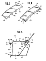
- Fig. 5 is a cross-section taken along line V-V of Fig. 1;
- Fig. 6 is an enlarged cross-section taken along line VI-VI of Fig. 1; and
- Fig. 7 is an enlarged cross-section taken along line V-V of Fig. 1.
- Referring now to the drawing, particularly to Fig. 1, a
cowling assembly 10 is provided between anengine hood 12 and awindshield 14 for reinforcing a vehicle body against lateral stress, for introducing ambient air for an air conditioner unit, and for receiving a wiper-and-washer assembly (not shown). Acowl top panel 16 is positioned on substantially the same plane as the engine hood to form a substantially smooth upper surface for the vehicle front portion. Between the cowltop panel 16 and the lower end of thewindshield 14, amolding 18 is provided for providing decorative appearance and sealing the cowl top panel to the windshield to rain water, washer fluid and so forth from entering the cowling assembly. - Figs. 2 to 5 show a detail of. the
cowling assembly 10 of Fig. 1. Thecowling assembly 10 comprises acowling box 20 and thecowl top panel 16. Cowltop panel 16 is formed into essentially thin box-shaped configuration with an upper planemajor section 22 and a verticalcircumferential wall section 24. A substantially L-shaped flange 26 extends from the base ofcircumferential wall section 24 at the side remote from thewindshield 14, to define awater drain groove 28 therewith. The horizontal section of the L-shaped flange 26 is formed with a plurality ofcircular openings 30 which are aligned withcircular openings 32 formed in alateral flange 34 extending from the top of the cowlingbox front panel 35. Thecowl top panel 16 has a plurality of strips ortabs 36 extending from the base ofcircumferential wall section 24 adjacent thewindshield 14. On both side portions ofcircumferential wall section 24 the cowltop panel 16 also has inwardly extendingretainer strips 38. -
Cowling box 20 comprises a dashupper panel 40, a cowlingbox front panel 35 and cowlingbox side panels 44.Front panel 35 hasflanges Flange 46 is fixedly secured to thehorizontal surface 48 of the dash upper panel. Theside panels 44 each has a substantially verticalmajor section 50 and a horizontalupper section 52 so that they have an essentially L-shaped configuration. Theside panel 44 also hasflanges horizontal surface 48 and the sloped surface of the dashupper panel 40. Theside panel 44 is further formed with ahook 45 which is adapted to engage with theretainer strips 38 on cowltop panel 16. Thus, the dashupper panel 40, afront panel 35 and the side panel define the substantially box form cowling box as assembled with an internal space therein. - A
stiffener 58 is inserted into the internal space of the cowlingbox 20.Stiffener 58 is formed with aflange 60 extending along the lower edge thereof. Theflange 60 is fixed onto the dashupper panel 40. Stiffener 58 substantially follows the slope ofwindshield 14. The upper edge of the stiffener is positioned behind the lower end of thewindshield 14 and is bonded onto the rear surface of the windshield with an adhesive 62. Anupper flange 64 of the dashupper panel 40 is secured to the upper end of the stiffener. -
Stiffener 58 is formed with a plurality ofelongated openings 66 along the lower edge of the windshield aligned with and adapted to receive the strips ortabs 36 of the cowltop panel 16, as shown in Fig. 5. - As shown in Fig. 4, a
resilient molding 68 is attached to the rear portion ofcircumferential wall section 24 of thecowl top panel 16.Molding 68 has plurality ofrecessed sections 70 for receiving thestrips 36, as shown in Figs. 5 and 6.Molding 68 has a rearwardly extendingtongue portion 72 which is adapted to sealingly and elastically contact the bottom front surface ofwindshield 14 to establish a water-tight seal therebetween. - Figure 7 is a partial sectional view of the cowl top panel and resilient molding assembly taken along line VII-VII in Figure 1 showing how the
circumferential wall section 24 between thetabs 36 is embedded in the body ofresilient molding 68 to secure the molding to the cowl top panel. - In the illustrated embodiment, after wiper-and-washer assemblies and so forth are mounted in the cowling box, cowl
top panel 16 is assembled to cowlingbox 20 by engagement of the strips ortabs 36 and theopenings 66. The front end of the cowltop panel 16 is thereafter of fixed toflange 34 of cowlingbox front panel 35 with afastener 74 passing through theopenings tongue portion 72 of themolding 68 sealingly contacts to the front surface of the lower end of thewindshield 14 in water-tight fashion. Thus, assembly of the cowling assembly onto the vehicle body is simple and 'effective. Further, the cowl top panel is detachable from the cowling box to allow easy maintenance or repair of equipment such as the wiper-and-washer assemblies. - The foregoing description has been set forth merely to illustrate the invention and is not intended to be limiting. Since modifications of the described embodiments incorporating the spirit and substance of the invention may occur to persons skilled in the art, 'the scope of the invention is to be limited solely with respect to the appended claims and equivalents.
Claims (5)
Applications Claiming Priority (2)
| Application Number | Priority Date | Filing Date | Title |
|---|---|---|---|
| JP124193/82 | 1982-07-16 | ||
| JP57124193A JPS5914577A (en) | 1982-07-16 | 1982-07-16 | Cowl construction for automobile |
Publications (2)
| Publication Number | Publication Date |
|---|---|
| EP0099115A2 true EP0099115A2 (en) | 1984-01-25 |
| EP0099115A3 EP0099115A3 (en) | 1986-04-16 |
Family
ID=14879283
Family Applications (1)
| Application Number | Title | Priority Date | Filing Date |
|---|---|---|---|
| EP83106835A Withdrawn EP0099115A3 (en) | 1982-07-16 | 1983-07-12 | Cowling structure for an automotive vehicle |
Country Status (2)
| Country | Link |
|---|---|
| EP (1) | EP0099115A3 (en) |
| JP (1) | JPS5914577A (en) |
Cited By (17)
| Publication number | Priority date | Publication date | Assignee | Title |
|---|---|---|---|---|
| DE3428293A1 (en) * | 1984-08-01 | 1986-02-13 | Adam Opel AG, 6090 Rüsselsheim | WINTER PANEL OUTER PLATE FOR A MOTOR VEHICLE |
| EP0403765A1 (en) * | 1989-06-22 | 1990-12-27 | Daimler-Benz Aktiengesellschaft | Arrangement and mounting for a cable harness in a frame structure of an automobile |
| FR2668110A1 (en) * | 1990-10-19 | 1992-04-24 | Renault | Scuttle channel (gutter) for receiving equipment for motor vehicles |
| US5108146A (en) * | 1991-07-22 | 1992-04-28 | Molmec, Inc. | Cowl grill to windshield lip seal |
| FR2710009A1 (en) * | 1993-09-17 | 1995-03-24 | Renault | Motor vehicle scuttle louvre structure |
| CN1095774C (en) * | 1998-06-17 | 2002-12-11 | 铃木株式会社 | Structure of resinous parts |
| US6715764B2 (en) * | 2001-04-19 | 2004-04-06 | Compagnie Plastic Omnium | Assemblage of two pieces of bodywork for uniting edge to edge, a piece of body work belonging to such an assemblage, a vehicle bumper and a vehicle fender |
| US6719362B1 (en) | 2002-10-31 | 2004-04-13 | Valeo Electrical Systems, Inc. | Integrated lower cowl/plenum and wiper drive module |
| US6814399B2 (en) | 2002-10-31 | 2004-11-09 | Valeo Electrical Systems, Inc. | Plastic molded product for aligning and supporting a rotatable shaft and process for making same |
| EP1571069A1 (en) * | 2004-03-03 | 2005-09-07 | Peugeot Citroen Automobiles | Fastening device for a body part of a motor vehicle |
| EP1878641A2 (en) | 2006-07-14 | 2008-01-16 | Dr.Ing. h.c.F. Porsche Aktiengesellschaft | Air-guiding device |
| FR2930227A1 (en) * | 2008-04-21 | 2009-10-23 | Renault Sas | PLASTIC AUCTION WINDOW FOR VEHICLE WITH DISMANTLING PART. |
| US7883141B2 (en) * | 2005-08-08 | 2011-02-08 | Mitsubishi Jidosha Kogyo Kabushiki Kaisha | Vehicle body structure |
| US7976097B2 (en) * | 2007-12-07 | 2011-07-12 | Nissan Motor Co., Ltd. | Cowl structure of vehicle |
| FR3020599A1 (en) * | 2014-05-05 | 2015-11-06 | Renault Sas | LATERAL CLOSURE ELEMENT FOR WATER BOX, CORRESPONDING WATER BOX AND VEHICLE THUS EQUIPPED |
| WO2017162936A1 (en) * | 2016-03-24 | 2017-09-28 | Psa Automobiles S.A. | Cowl assembly and device for mounting such a cowl assembly on the bodyshell of a motor vehicle |
| FR3052432A1 (en) * | 2016-06-14 | 2017-12-15 | Peugeot Citroen Automobiles Sa | ASSEMBLY COMPRISING A SIDE FINISHING ELEMENT OF A VEHICLE AWNING GRID AND DETROMPING DEVICE |
Families Citing this family (2)
| Publication number | Priority date | Publication date | Assignee | Title |
|---|---|---|---|---|
| JPH01278833A (en) * | 1988-04-29 | 1989-11-09 | Mazda Motor Corp | Windshield pane supporting structure for vehicle |
| JP6867881B2 (en) * | 2017-05-31 | 2021-05-12 | 日本プラスト株式会社 | Cowl cover |
Citations (3)
| Publication number | Priority date | Publication date | Assignee | Title |
|---|---|---|---|---|
| FR2445776A1 (en) * | 1979-01-02 | 1980-08-01 | Citroen Sa | Shock-absorbing mounting for automobile windscreen - has housing joined to body by deformable joint supported by ribs with absorbent filling |
| GB2065039A (en) * | 1979-11-19 | 1981-06-24 | Nissan Motor | Automotive vehicle cowl construction |
| JPS5712344A (en) * | 1980-06-26 | 1982-01-22 | Doro Doshitsu Chiyousa Kk | Method and device for horizontal sampling of earth free from disorder |
-
1982
- 1982-07-16 JP JP57124193A patent/JPS5914577A/en active Pending
-
1983
- 1983-07-12 EP EP83106835A patent/EP0099115A3/en not_active Withdrawn
Patent Citations (3)
| Publication number | Priority date | Publication date | Assignee | Title |
|---|---|---|---|---|
| FR2445776A1 (en) * | 1979-01-02 | 1980-08-01 | Citroen Sa | Shock-absorbing mounting for automobile windscreen - has housing joined to body by deformable joint supported by ribs with absorbent filling |
| GB2065039A (en) * | 1979-11-19 | 1981-06-24 | Nissan Motor | Automotive vehicle cowl construction |
| JPS5712344A (en) * | 1980-06-26 | 1982-01-22 | Doro Doshitsu Chiyousa Kk | Method and device for horizontal sampling of earth free from disorder |
Cited By (25)
| Publication number | Priority date | Publication date | Assignee | Title |
|---|---|---|---|---|
| DE3428293A1 (en) * | 1984-08-01 | 1986-02-13 | Adam Opel AG, 6090 Rüsselsheim | WINTER PANEL OUTER PLATE FOR A MOTOR VEHICLE |
| US4679845A (en) * | 1984-08-01 | 1987-07-14 | General Motors Corporation | Motor vehicle windshield cowl plate |
| EP0403765A1 (en) * | 1989-06-22 | 1990-12-27 | Daimler-Benz Aktiengesellschaft | Arrangement and mounting for a cable harness in a frame structure of an automobile |
| US5135187A (en) * | 1989-06-22 | 1992-08-04 | Daimler-Benz Ag | Arrangement for holding and laying a multiplicity of jointly guided cables in an installation space of a motor vehicle |
| FR2668110A1 (en) * | 1990-10-19 | 1992-04-24 | Renault | Scuttle channel (gutter) for receiving equipment for motor vehicles |
| US5108146A (en) * | 1991-07-22 | 1992-04-28 | Molmec, Inc. | Cowl grill to windshield lip seal |
| FR2710009A1 (en) * | 1993-09-17 | 1995-03-24 | Renault | Motor vehicle scuttle louvre structure |
| CN1095774C (en) * | 1998-06-17 | 2002-12-11 | 铃木株式会社 | Structure of resinous parts |
| US6715764B2 (en) * | 2001-04-19 | 2004-04-06 | Compagnie Plastic Omnium | Assemblage of two pieces of bodywork for uniting edge to edge, a piece of body work belonging to such an assemblage, a vehicle bumper and a vehicle fender |
| US6719362B1 (en) | 2002-10-31 | 2004-04-13 | Valeo Electrical Systems, Inc. | Integrated lower cowl/plenum and wiper drive module |
| US6814399B2 (en) | 2002-10-31 | 2004-11-09 | Valeo Electrical Systems, Inc. | Plastic molded product for aligning and supporting a rotatable shaft and process for making same |
| EP1571069A1 (en) * | 2004-03-03 | 2005-09-07 | Peugeot Citroen Automobiles | Fastening device for a body part of a motor vehicle |
| US7883141B2 (en) * | 2005-08-08 | 2011-02-08 | Mitsubishi Jidosha Kogyo Kabushiki Kaisha | Vehicle body structure |
| EP1878641A3 (en) * | 2006-07-14 | 2008-02-27 | Dr.Ing. h.c.F. Porsche Aktiengesellschaft | Air-guiding device |
| US7464979B2 (en) | 2006-07-14 | 2008-12-16 | Dr. Ing. H.C. F. Porsche Ag | Wind deflecting device |
| EP1878641A2 (en) | 2006-07-14 | 2008-01-16 | Dr.Ing. h.c.F. Porsche Aktiengesellschaft | Air-guiding device |
| US7976097B2 (en) * | 2007-12-07 | 2011-07-12 | Nissan Motor Co., Ltd. | Cowl structure of vehicle |
| FR2930227A1 (en) * | 2008-04-21 | 2009-10-23 | Renault Sas | PLASTIC AUCTION WINDOW FOR VEHICLE WITH DISMANTLING PART. |
| WO2009136108A2 (en) * | 2008-04-21 | 2009-11-12 | Renault S.A.S. | Plastic scuttle grille for vehicle with detachable part |
| WO2009136108A3 (en) * | 2008-04-21 | 2009-12-30 | Renault S.A.S. | Plastic scuttle grille for vehicle with detachable part |
| FR3020599A1 (en) * | 2014-05-05 | 2015-11-06 | Renault Sas | LATERAL CLOSURE ELEMENT FOR WATER BOX, CORRESPONDING WATER BOX AND VEHICLE THUS EQUIPPED |
| WO2017162936A1 (en) * | 2016-03-24 | 2017-09-28 | Psa Automobiles S.A. | Cowl assembly and device for mounting such a cowl assembly on the bodyshell of a motor vehicle |
| FR3049259A1 (en) * | 2016-03-24 | 2017-09-29 | Peugeot Citroen Automobiles Sa | AN AWNING ASSEMBLY AND DEVICE FOR MOUNTING AN SUCH AN ASSEMBLY ON THE BODY OF A MOTOR VEHICLE. |
| CN109153413A (en) * | 2016-03-24 | 2019-01-04 | 标致雪铁龙汽车股份有限公司 | Vent flap component and for the vent flap component to be mounted on the mounting device in motor vehicle body |
| FR3052432A1 (en) * | 2016-06-14 | 2017-12-15 | Peugeot Citroen Automobiles Sa | ASSEMBLY COMPRISING A SIDE FINISHING ELEMENT OF A VEHICLE AWNING GRID AND DETROMPING DEVICE |
Also Published As
| Publication number | Publication date |
|---|---|
| JPS5914577A (en) | 1984-01-25 |
| EP0099115A3 (en) | 1986-04-16 |
Similar Documents
| Publication | Publication Date | Title |
|---|---|---|
| EP0099115A2 (en) | Cowling structure for an automotive vehicle | |
| US5799442A (en) | Door glass weather strip | |
| US5873623A (en) | Vehicle door drain slot plug | |
| US5297843A (en) | Window molding for automobile | |
| US4719736A (en) | Removable window assembly | |
| US4161851A (en) | Motor vehicle window assembly | |
| CN215360868U (en) | Rain shield for vehicle body | |
| JPS60248429A (en) | Door structure for car | |
| JPH0415527Y2 (en) | ||
| JPS5826180Y2 (en) | Automotive door seal structure | |
| JPH0468176B2 (en) | ||
| JPH0724260Y2 (en) | Car door | |
| JPH09156431A (en) | Fitting structure for dash silencer | |
| JPS6246377B2 (en) | ||
| JPH0356407Y2 (en) | ||
| JP2001071938A (en) | Fixing structure for rear end of vehicular cowl louver | |
| JPS6241897Y2 (en) | ||
| KR0123037Y1 (en) | Construction for fixing a glass for a vehicle | |
| KR200229255Y1 (en) | Cowl grille for car | |
| JPH11227545A (en) | Water cut-off structure of circuit body installation part for car door | |
| JPH10218029A (en) | Hood seal mounting structure of automobile | |
| JPS5831696Y2 (en) | Automotive quarter window weather strip structure | |
| JPS5820442Y2 (en) | Automotive defroster nozzle | |
| JPS6326279Y2 (en) | ||
| KR200257924Y1 (en) | Noise reduction structure of automobile dust cover |
Legal Events
| Date | Code | Title | Description |
|---|---|---|---|
| PUAI | Public reference made under article 153(3) epc to a published international application that has entered the european phase |
Free format text: ORIGINAL CODE: 0009012 |
|
| 17P | Request for examination filed |
Effective date: 19830712 |
|
| AK | Designated contracting states |
Designated state(s): DE FR GB |
|
| RAP1 | Party data changed (applicant data changed or rights of an application transferred) |
Owner name: NISSAN MOTOR CO., LTD. |
|
| PUAL | Search report despatched |
Free format text: ORIGINAL CODE: 0009013 |
|
| AK | Designated contracting states |
Kind code of ref document: A3 Designated state(s): DE FR GB |
|
| STAA | Information on the status of an ep patent application or granted ep patent |
Free format text: STATUS: THE APPLICATION IS DEEMED TO BE WITHDRAWN |
|
| 18D | Application deemed to be withdrawn |
Effective date: 19860201 |
|
| RIN1 | Information on inventor provided before grant (corrected) |
Inventor name: OTSU, MORIO Inventor name: NAKAMURA, YOSHIHARU |