EP0099546A1 - Rotary actuator - Google Patents
Rotary actuator Download PDFInfo
- Publication number
- EP0099546A1 EP0099546A1 EP83106886A EP83106886A EP0099546A1 EP 0099546 A1 EP0099546 A1 EP 0099546A1 EP 83106886 A EP83106886 A EP 83106886A EP 83106886 A EP83106886 A EP 83106886A EP 0099546 A1 EP0099546 A1 EP 0099546A1
- Authority
- EP
- European Patent Office
- Prior art keywords
- pistons
- rotary drive
- cylinder
- drive shaft
- drive according
- Prior art date
- Legal status (The legal status is an assumption and is not a legal conclusion. Google has not performed a legal analysis and makes no representation as to the accuracy of the status listed.)
- Withdrawn
Links
Images
Classifications
-
- F—MECHANICAL ENGINEERING; LIGHTING; HEATING; WEAPONS; BLASTING
- F15—FLUID-PRESSURE ACTUATORS; HYDRAULICS OR PNEUMATICS IN GENERAL
- F15B—SYSTEMS ACTING BY MEANS OF FLUIDS IN GENERAL; FLUID-PRESSURE ACTUATORS, e.g. SERVOMOTORS; DETAILS OF FLUID-PRESSURE SYSTEMS, NOT OTHERWISE PROVIDED FOR
- F15B15/00—Fluid-actuated devices for displacing a member from one position to another; Gearing associated therewith
- F15B15/02—Mechanical layout characterised by the means for converting the movement of the fluid-actuated element into movement of the finally-operated member
- F15B15/06—Mechanical layout characterised by the means for converting the movement of the fluid-actuated element into movement of the finally-operated member for mechanically converting rectilinear movement into non- rectilinear movement
- F15B15/065—Mechanical layout characterised by the means for converting the movement of the fluid-actuated element into movement of the finally-operated member for mechanically converting rectilinear movement into non- rectilinear movement the motor being of the rack-and-pinion type
Definitions
- a slide strip is arranged at the ends of each piston.
- At least one of the pistons can be limited in its stroke by a stop which is adjustable in the working direction of the pistons.
- Figures 1 to 4 show different embodiments of the rotary drive according to the invention in cross section.
Abstract
Description
Die Erfindung betrifft einen Drehantrieb mit zwei Kolben für Ausführen von hin- hergehenden Bewegungen in entgegengesetzten Richtungen unter der Einwirkung des Druckes eines Strömungsmittels in einem Zylinder, bei dem die Kolben innen als Zahnstangen ausgebildet sind und die Zahnstangen mit einem gemeinsamen Ritzrel kämmen, das mit einer Antriebswelle des Drehantriebs verbunden ist.The invention relates to a rotary drive with two pistons for executing reciprocating movements in opposite directions under the action of the pressure of a fluid in a cylinder, in which the pistons are designed as toothed racks on the inside and the toothed racks mesh with a common pinion, which with a Drive shaft of the rotary drive is connected.
Ein derartiger Drehantrieb ist aus der DE-PS 16 01 746 bekannt. Dieser Antrieb wird vor allem in der Steuerungstechnik eingesetzt und dient zur Betätigung von Armaturen. Die Kolben sind relativ zu dem Ritzel symmetrisch zueinander angeordnet. Die Bewegungen der beiden Kolben sind durch das Ritzel miteinander gekoppelt, wobei sich die Kolben je nach dem Relativdruck zwischen den beiden Kolben und außerhalb davon entweder auseinander oder aufeinander zu bewegen und auf diese Weise eine Drehbewegung des Ritzels und der damit verbundenen Antriebswelle bewirken.Such a rotary drive is known from DE-PS 16 01 746. This actuator is mainly used in control technology and is used to operate fittings. The pistons are arranged symmetrically to one another relative to the pinion. The movements of the two pistons are coupled to one another by the pinion, the pistons depending on the relative pressure between the two pistons and outside of them either moving apart or towards one another and in this way causing the pinion and the drive shaft connected to it to rotate.
Die Kolben des Drehantriebs neigen dazu, sich zu verklemmen und festzufressen. Um dies zu verhindern, ist in der DE-PS 16 01 746 bereits vorgeschlagen worden, die Kolben in am Zylinder befestigten Führungsstangen zu führen. Allerdings hat diese Konstruktion den Nachteil, daß die Führungsstangen sehr präzise gearbeitet und eingepaßt sein müssen, um einerseits ein möglichst reibungsarmes Gleiten der Kolben zu ermöglichen und um andererseits die erforderliche Dichtheit der Kolben zu gewährleisten.The pistons of the rotary actuator tend to jam and seize. To prevent this, is in the DE-PS 16 01 746 has already been proposed to guide the pistons in guide rods attached to the cylinder. However, this construction has the disadvantage that the guide rods have to be worked and fitted very precisely in order on the one hand to allow the pistons to slide with as little friction as possible and on the other hand to ensure the necessary tightness of the pistons.
Der vorliegenden Erfindung liegt daher die Aufgabe zugrunde, einen Drehantrieb der eingangs genannten Art zu entwickeln, der bei hoher Betriebssicherheit kostengünstig herstellbar ist.The present invention is therefore based on the object of developing a rotary drive of the type mentioned at the outset which can be produced inexpensively with high operational reliability.
Diese Aufgabe wird erfindungsgemäß dadurch gelöst, daß die Kolben auf ihren Oberflächen mit Gleitstreifen versehen sind, auf denen die Kolben im Zylinder gelagert sind.This object is achieved in that the pistons are provided on their surfaces with sliding strips on which the pistons are mounted in the cylinder.
Erfindungsgemäß gleiten die Kolben unmittelbar auf der Innenwand des Zylinders. Da die Kolben nahezu ohne Spiel im Zylinder laufen, ist ein Verkippen oder gar Festfressen der Kolben ausgeschlossen. Der Aufbau des Drehantriebs ist trotzder hohen Betriebssicherheit einfach und damit kostengünstig.According to the invention, the pistons slide directly on the inner wall of the cylinder. Since the pistons run with almost no play in the cylinder, the pistons cannot tilt or seize. The structure of the rotary drive is simple and therefore inexpensive despite the high level of operational reliability.
Gemäß einer bevorzugten Ausgestaltung des Erfindungsgegenstandes ist jeweils ein Gleitstreifen an den Enden eines jeden Kolben angeordnet.According to a preferred embodiment of the subject matter of the invention, a slide strip is arranged at the ends of each piston.
Es ist von Vorteil, wenn die Gleitstreifen aus mehreren Schichten zusammengesetzt sind.It is advantageous if the sliding strips are composed of several layers.
Bei einer bevorzugten Weiterbildung des Erfindungsgegenstandes enthalten die Gleitstreifen eine innere Schicht aus Stahl, eine mittlere Schicht aus Bronze und eine äußere Schicht aus Polytetrafluoräthylen. Die äußerste Schicht aus Polytetrafluoräthylen, die dünn im Vergleich zu den anderen Schichten ist, reibt sich beim Gebrauch des Dreh- antriebs sehr schnell ab. Der Polytetrafluoräthylen-Abrieb füllt die Poren der Zylinderwand und dient als Schmierfilm zwischen Kolben und Zylinder.In a preferred development of the subject matter of the invention, the sliding strips contain an inner layer made of steel, a middle layer made of bronze and an outer layer made of polytetrafluoroethylene. The outermost layer of polytetrafluoroethylene, which is thin in comparison to the other layers, rubs when using the rotary - drive very fast. The polytetrafluoroethylene abrasion fills the pores of the cylinder wall and serves as a lubricating film between the piston and the cylinder.
Es erweist sich als zweckmäßig, wenn gemäß einer weiteren Ausgestaltung des Erfindungsgegenstandes zumindest einer der Kolben durch einen in Arbeitsrichtung der Kolben verstellbaren Anschlag in seinem Hub begrenzbar ist.It proves to be expedient if, according to a further embodiment of the subject of the invention, at least one of the pistons can be limited in its stroke by a stop which is adjustable in the working direction of the pistons.
Auf diese Weise läßt sich der Drehwinkel des erfindungsgemäßen Drehantriebs in einer oder in beiden Drehrichtungen verstellen. Der Drehantrieb läßt sich dadurch universell einsetzen, so daß Betriebs- und Lagerhaltungskosten gesenkt werden können.In this way, the angle of rotation of the rotary drive according to the invention can be adjusted in one or in both directions of rotation. The rotary drive can thus be used universally, so that operating and storage costs can be reduced.
Zur Erhöhung der Betriebssicherheit wird in weiterer Ausgestaltung des erfindungsgemäßen Drehantriebs vorgeschlagen, daß die Antriebswelle einstückig ausgebildet ist und auf beiden Seiten des Ritzels dieselbe Querschnittsfläche aufweist.In order to increase operational safety, it is proposed in a further embodiment of the rotary drive according to the invention that the drive shaft is formed in one piece and has the same cross-sectional area on both sides of the pinion.
Da zum Auseinanderdrücken der Kolben ein Strömungsmittel zwischen die Kolben eingepreßt wird, ist die resultierende Schubkraft, die das Strömungsmittel auf die im Zylindergehäuse gelagerte Antriebswelle ausübt, bei dieser Ausgestaltung gleich Null. Druckbelastungen durch die Antriebswelle auf die Spindel angeschlossener Bauteile, z.B. eine Armaturenspindel, entfallen. Als weiterer Vorteil der Antriebswelle mit beidseitig gleichen geometrischen Abmessungen ist anzuführen, daß der Drehantrieb je nach Einbaulage rechts- oder linksdrehend einsetzbar ist, so daß sich die Lagerhaltung um die Hälfte reduziert.Since a fluid is pressed between the pistons to push the pistons apart, the resulting thrust force which the fluid exerts on the drive shaft mounted in the cylinder housing is zero in this embodiment. Pressure loads from the drive shaft on the spindle of connected components, e.g. an armature spindle, omitted. Another advantage of the drive shaft with the same geometrical dimensions on both sides is that the rotary drive can be used clockwise or counterclockwise depending on the installation position, so that the inventory is reduced by half.
Die Erfindung sowie weitere Einzelheiten der Erfindung werden anhand von schematisch dargestellten Ausführungsbeispielen näher erläutert.The invention and further details of the invention are explained in more detail with reference to schematically illustrated exemplary embodiments.
Hierbei zeigen die Figuren 1 bis 4 verschiedene Ausführungsformen des erfindungsgemäßen Drehantriebs im Querschnitt.Figures 1 to 4 show different embodiments of the rotary drive according to the invention in cross section.
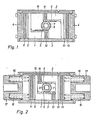
Figur 1 zeigt einen erfindungsgemäßen Drehantrieb mit zwei Kolben 1, 2 in einem Zylinder 3. Die Kolben 1, 2 und der Zylinder 3 sind beispielsweise aus Aluminium gefertigt. Der Zylinder 3 ist an seinen Enden durch Endkappen 4 verschlossen. Die Kolben sind an ihren Innenseiten als Zahnstangen 5, 6 ausgebildet, wobei die Zahnstangen 5,6 mit einem gemeinsamen Ritzel 7 kämmen. Das Ritzel 7 ist mit einer Antriebswelle 8 des Drehantriebs verbunden, an die beispielsweise eine nicht dargestellte Armaturenspindel angeschlossen ist. Die Kolben 1, 2 sind mit Dichtringen 9, 10 versehen.Figure 1 shows a rotary drive according to the invention with two
Erfindungsgemäß sind die Kolben 1, 2 mittels Gleitstreifen 11, 12 und 13,14 im Zylinder 3 gelagert. Jeweils ein Gleitstreifen befindet sich am äußeren Randbereich der Kolben 1, 2 wobei immer ein Gleitstreifen 11,13 sich über den gesamten Umfang der Kolben 1,2 erstreckt, während der andere der Gleitstreifen 12,14 sich am vorderen Ende des als Zahnstange 5,6 ausgebildeten Teils des Kolbens befindet. Die Gleitstreifen 11 bis 14 sind aus drei Schichten zusammengesetzt,wobei die innere Schicht aus Edelstahl, die mittlere aus Bronze und die äußere Schicht aus Polytetrafluoräthylen besteht. Das Polytetrafluor- äthylenmaterial reibt sich beim Gebrauch des Drehantriebs sehr schnell ab und bildet einen Gleitfilm, der sich teilweise in die Poren des Zylinder-Wandmaterials legt und auf dem die Kolben 1,2 im Zylinder 3 gleiten.According to the invention, the
Der Zylinder 3 enthält Zuführungen 15 für ein Strömungsmittel, die in die Zylinderkammer an der Außenseite der Kolben 1,2 münden, sowie eine in der Figur nicht dargestellte Zuführung, die in den Zylinderraum zwischen den beiden Kolben 1, 2 mündet. Unter der Einwirkung des Druckes des Strömungsmittels führen die Kolben 1, 2 in dem Zylinder 3 hin- und hergehende Bewegungen aus, wobei das Ritzel 7 zwischen einer Position von 0° und 90° gedreht wird. Bei der Bewegung sind die Kolben 1, 2 auf den Gleitstreifen 11 bis 14 gelagert, die ein Verkippen der Kolben 1, 2 sicher verhindern.The
Die Antriebswelle 8 ist oberhalb und unterhalb der Zeichenebene in der Zylinderwand in Lagerbuchsen gelagert. Der Durchmesser der Antriebswelle ist auf beiden Seiten des Ritzels gleich groß, so daß durch den Druck des Strömungsmittels zwischen den beiden Kolben keine resultierende Kraft auf die Antriebswelle entsteht.The
Der Drehantrieb gemäß Figur 2 unterscheidet sich von demjenigen gemäß Figur 1 im wesentlichen dadurch, daß die Rückstellung der Kolben 1, 2 nicht durch den Druck eines Strömungsmittels, sondern mittels Druckfedern 16 erfolgt, welche in Endkappen 17 des Zylinders 3 eingelassen sind.The rotary drive according to FIG. 2 differs from that according to FIG. 1 essentially in that the
Das Strömungsmittel wird nur in den inneren Zylinderraum zwischen den Kolben 1, 2 geführt. Diese Ausführung hat den Vorteil, daß bei einem Druckausfall das Ritzel 7 und damit auch die zu schaltende Armatur automatisch in ihre Nullposition gestellt werden.The fluid is only led into the inner cylinder space between the
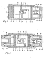
Figur 3 zeigt einen Drehantrieb ähnlich dem Drehantrieb gemäß Figur 1. Im Unterschied dazu ist hier ein Anschlag vorgesehen, mit dem der Hub eines der Kolben verstellbar ist. Beispielweise lassen sich beide Endlagen um + 11,25° verstellen, so daß der Gesamtschwenkbereich des Drehantriebs 0 bis 112,5° beträgt.FIG. 3 shows a rotary drive similar to the rotary drive according to FIG. 1. In contrast to this, a stop is provided here with which the stroke of one of the pistons can be adjusted. B eispielweise both end positions to + 11.25 ° leave adjust so that the total swivel range of the rotary actuator is 0 to 112.5 °.
Zur Hubbegrenzung weist eine Endkappe 18 eine zentrale Durchführung auf, durch die eine mit einem der Kolben verbundene Hülse 19 geführt ist. Die Hülse 19 weist ein Innengewinde auf, in das eine Schraube 20 eingeschraubt ist..Der Schraubenkopf ist größer als der Durchmesser der burchführung für die Hülse und ist in einer an die Durchführung sich anschließende Bohrung 21 mit größerem Durchmesser als die Durchführung hin- und herbewegbar. Die Bohrung 21 weist an ihrer Außenseite ein Gewinde auf, in das ein Deckel 22 eingeschraubt ist.To limit the stroke, an
Bei Bewegung der Kolben 1;2 bewegen sich die Hülse 19 und die Schraube 20 mit dem Kolben 2. Der Kohlbenhub. wird dabei in der einen Richtung durch den Anschlag der Schraube 20 am inneren Rand 23 der Bohrung 21 und in der anderen Richtung durch den Anschlag der Schraube 20 am Deckel 22 begrenzt. Durch Verdrehen der Schraube 20 und des Deckels 21 lassen sich die Endlagen der Kolben 1, 2 verändern.When the
Figur 4 zeigt einen Drehantrieb ähnlich demjenigen gemäß Figur 2, jedoch ist hier wie bei dem Drehantrieb nach Figur 3, der Hub der Kolben 1, 2 verstellbar.FIG. 4 shows a rotary drive similar to that according to FIG. 2, but here, as in the rotary drive according to FIG. 3, the stroke of the
Claims (6)
Applications Claiming Priority (2)
| Application Number | Priority Date | Filing Date | Title |
|---|---|---|---|
| DE3227275 | 1982-07-21 | ||
| DE19823227275 DE3227275A1 (en) | 1982-07-21 | 1982-07-21 | ROTARY DRIVE |
Publications (1)
| Publication Number | Publication Date |
|---|---|
| EP0099546A1 true EP0099546A1 (en) | 1984-02-01 |
Family
ID=6168970
Family Applications (1)
| Application Number | Title | Priority Date | Filing Date |
|---|---|---|---|
| EP83106886A Withdrawn EP0099546A1 (en) | 1982-07-21 | 1983-07-13 | Rotary actuator |
Country Status (2)
| Country | Link |
|---|---|
| EP (1) | EP0099546A1 (en) |
| DE (1) | DE3227275A1 (en) |
Cited By (3)
| Publication number | Priority date | Publication date | Assignee | Title |
|---|---|---|---|---|
| EP0344126A1 (en) * | 1988-05-24 | 1989-11-29 | Aurelio Messina | Improved actuator for actuating valves |
| EP0697527A3 (en) * | 1994-06-15 | 1996-12-18 | Prime Actuator Control Systems | End-stop |
| EP1486680A1 (en) * | 2003-06-13 | 2004-12-15 | Dynamic Air, Inc. | Actuator |
Citations (5)
| Publication number | Priority date | Publication date | Assignee | Title |
|---|---|---|---|---|
| US2689380A (en) * | 1951-01-29 | 1954-09-21 | Glacier Co Ltd | Method of making bearings |
| US3982725A (en) * | 1974-06-27 | 1976-09-28 | Keystone International, Inc. | Valve actuator |
| DE2627604A1 (en) * | 1975-06-19 | 1977-01-13 | Norbro Pneumatics Ltd | ROTARY MEDIUM ACTUATOR |
| FR2457425A1 (en) * | 1979-05-25 | 1980-12-19 | Gachot Jean | Operator for remote controlled valve - has housing forming cylinder, and plunger with PTFE guides, energising rack driving output shaft pinion |
| EP0040976A1 (en) * | 1980-05-27 | 1981-12-02 | Worcester Controls (U.K.) Limited | Rotary actuators |
Family Cites Families (5)
| Publication number | Priority date | Publication date | Assignee | Title |
|---|---|---|---|---|
| GB814475A (en) * | 1956-07-16 | 1959-06-03 | Steiner Carl | A fluid pressure motor |
| US1667559A (en) * | 1924-07-11 | 1928-04-24 | Trico Products Corp | Windshield-cleaner motor |
| AT119846B (en) * | 1929-04-16 | 1930-11-10 | Knorr Bremse Ag | Pistons, especially for small, fast running, crossheadless compressors. |
| DE1953440U (en) * | 1966-11-02 | 1967-01-12 | Otto Schuchmacher K G | GUIDE RING FOR PISTON. |
| DE2239488A1 (en) * | 1972-08-11 | 1974-02-21 | Bauer Kompressoren | PISTON MACHINE, IN PARTICULAR DRY RUNNING PISTON COMPRESSORS, WITH GUIDE RING |
-
1982
- 1982-07-21 DE DE19823227275 patent/DE3227275A1/en not_active Ceased
-
1983
- 1983-07-13 EP EP83106886A patent/EP0099546A1/en not_active Withdrawn
Patent Citations (5)
| Publication number | Priority date | Publication date | Assignee | Title |
|---|---|---|---|---|
| US2689380A (en) * | 1951-01-29 | 1954-09-21 | Glacier Co Ltd | Method of making bearings |
| US3982725A (en) * | 1974-06-27 | 1976-09-28 | Keystone International, Inc. | Valve actuator |
| DE2627604A1 (en) * | 1975-06-19 | 1977-01-13 | Norbro Pneumatics Ltd | ROTARY MEDIUM ACTUATOR |
| FR2457425A1 (en) * | 1979-05-25 | 1980-12-19 | Gachot Jean | Operator for remote controlled valve - has housing forming cylinder, and plunger with PTFE guides, energising rack driving output shaft pinion |
| EP0040976A1 (en) * | 1980-05-27 | 1981-12-02 | Worcester Controls (U.K.) Limited | Rotary actuators |
Cited By (4)
| Publication number | Priority date | Publication date | Assignee | Title |
|---|---|---|---|---|
| EP0344126A1 (en) * | 1988-05-24 | 1989-11-29 | Aurelio Messina | Improved actuator for actuating valves |
| EP0697527A3 (en) * | 1994-06-15 | 1996-12-18 | Prime Actuator Control Systems | End-stop |
| EP1486680A1 (en) * | 2003-06-13 | 2004-12-15 | Dynamic Air, Inc. | Actuator |
| US6959913B2 (en) | 2003-06-13 | 2005-11-01 | Dynamic Air Inc. | Actuator |
Also Published As
| Publication number | Publication date |
|---|---|
| DE3227275A1 (en) | 1984-01-26 |
Similar Documents
| Publication | Publication Date | Title |
|---|---|---|
| DE19950582C1 (en) | Actuating device for a rotatable closure part of a valve | |
| DE3122598C1 (en) | Adjustable vane pump | |
| EP3417183B1 (en) | Ball joint | |
| DE4242601A1 (en) | Fluid power cylinder with adjustable stroke | |
| DE2451380A1 (en) | AXIAL PISTON MACHINE WITH ADJUSTABLE STROKE | |
| EP1215412B1 (en) | Piston-cylinder unit with an adjuster | |
| DE3204067C2 (en) | ||
| EP0622574A2 (en) | Actuating device for a rotatable valve shut-off element | |
| EP0099546A1 (en) | Rotary actuator | |
| DE3222982A1 (en) | Rotary-piston cylinder | |
| DE1576142C3 (en) | Hydraulically or pneumatically operated rotary actuator | |
| EP0212299B1 (en) | Hydraulic power actuator with a non-rotating piston rod and a hydrostatic bearing | |
| DE1812635A1 (en) | Radial piston pump | |
| DE8220817U1 (en) | ROTARY DRIVE | |
| EP1416165A2 (en) | Pneumatic cylinder | |
| AT392340B (en) | SANITARY SHUT-OFF VALVE TOP | |
| EP0089568B1 (en) | Fluid operated linear-to-rotary actuator | |
| DE2655493C3 (en) | Pressurized medium-actuated rotary drive for a valve | |
| DE2461236A1 (en) | SWING MOTOR | |
| DE914801C (en) | Lubrication pump | |
| EP0979952A2 (en) | Rotary actuator, especially pneumatic rotary actuator | |
| DE2649053C3 (en) | Valve with a main and an auxiliary closing part | |
| EP0759509A2 (en) | Fluid-powered rotary actuator | |
| AT391175B (en) | SANITARY SHUT-OFF VALVE TOP | |
| DE2254751B2 (en) | Radial piston machine |
Legal Events
| Date | Code | Title | Description |
|---|---|---|---|
| PUAI | Public reference made under article 153(3) epc to a published international application that has entered the european phase |
Free format text: ORIGINAL CODE: 0009012 |
|
| AK | Designated contracting states |
Designated state(s): AT BE DE FR GB IT |
|
| STAA | Information on the status of an ep patent application or granted ep patent |
Free format text: STATUS: THE APPLICATION IS DEEMED TO BE WITHDRAWN |
|
| 18D | Application deemed to be withdrawn |
Effective date: 19841002 |
|
| RIN1 | Information on inventor provided before grant (corrected) |
Inventor name: HEUSCHROECK, HANS |