EP0099778A1 - Mechanically scanned target holder - Google Patents
Mechanically scanned target holder Download PDFInfo
- Publication number
- EP0099778A1 EP0099778A1 EP83401282A EP83401282A EP0099778A1 EP 0099778 A1 EP0099778 A1 EP 0099778A1 EP 83401282 A EP83401282 A EP 83401282A EP 83401282 A EP83401282 A EP 83401282A EP 0099778 A1 EP0099778 A1 EP 0099778A1
- Authority
- EP
- European Patent Office
- Prior art keywords
- support
- plate
- target holder
- relative
- supports
- Prior art date
- Legal status (The legal status is an assumption and is not a legal conclusion. Google has not performed a legal analysis and makes no representation as to the accuracy of the status listed.)
- Withdrawn
Links
Images

Classifications
-
- H—ELECTRICITY
- H01—ELECTRIC ELEMENTS
- H01J—ELECTRIC DISCHARGE TUBES OR DISCHARGE LAMPS
- H01J37/00—Discharge tubes with provision for introducing objects or material to be exposed to the discharge, e.g. for the purpose of examination or processing thereof
- H01J37/30—Electron-beam or ion-beam tubes for localised treatment of objects
- H01J37/317—Electron-beam or ion-beam tubes for localised treatment of objects for changing properties of the objects or for applying thin layers thereon, e.g. for ion implantation
- H01J37/3171—Electron-beam or ion-beam tubes for localised treatment of objects for changing properties of the objects or for applying thin layers thereon, e.g. for ion implantation for ion implantation
-
- C—CHEMISTRY; METALLURGY
- C23—COATING METALLIC MATERIAL; COATING MATERIAL WITH METALLIC MATERIAL; CHEMICAL SURFACE TREATMENT; DIFFUSION TREATMENT OF METALLIC MATERIAL; COATING BY VACUUM EVAPORATION, BY SPUTTERING, BY ION IMPLANTATION OR BY CHEMICAL VAPOUR DEPOSITION, IN GENERAL; INHIBITING CORROSION OF METALLIC MATERIAL OR INCRUSTATION IN GENERAL
- C23C—COATING METALLIC MATERIAL; COATING MATERIAL WITH METALLIC MATERIAL; SURFACE TREATMENT OF METALLIC MATERIAL BY DIFFUSION INTO THE SURFACE, BY CHEMICAL CONVERSION OR SUBSTITUTION; COATING BY VACUUM EVAPORATION, BY SPUTTERING, BY ION IMPLANTATION OR BY CHEMICAL VAPOUR DEPOSITION, IN GENERAL
- C23C14/00—Coating by vacuum evaporation, by sputtering or by ion implantation of the coating forming material
- C23C14/22—Coating by vacuum evaporation, by sputtering or by ion implantation of the coating forming material characterised by the process of coating
- C23C14/50—Substrate holders
- C23C14/505—Substrate holders for rotation of the substrates
-
- H—ELECTRICITY
- H01—ELECTRIC ELEMENTS
- H01L—SEMICONDUCTOR DEVICES NOT COVERED BY CLASS H10
- H01L21/00—Processes or apparatus adapted for the manufacture or treatment of semiconductor or solid state devices or of parts thereof
- H01L21/67—Apparatus specially adapted for handling semiconductor or electric solid state devices during manufacture or treatment thereof; Apparatus specially adapted for handling wafers during manufacture or treatment of semiconductor or electric solid state devices or components ; Apparatus not specifically provided for elsewhere
- H01L21/68—Apparatus specially adapted for handling semiconductor or electric solid state devices during manufacture or treatment thereof; Apparatus specially adapted for handling wafers during manufacture or treatment of semiconductor or electric solid state devices or components ; Apparatus not specifically provided for elsewhere for positioning, orientation or alignment
Definitions
- the present invention relates to a target holder with mechanical scanning allowing a uniform deposit or implantation on one or more targets mounted on the device, this deposit or this implantation being obtained using an energy source.
- targets be struck by an energy beam or a flow of particles, for example the implantation of ions on a silicon wafer intended for the production of integrated circuits. Since the diameter of the beam is generally much smaller than the dimensions of the target, the main problem which arises in this kind of application is that of the homogeneity of the implantation.
- the various systems used to date can be classified into two main categories: mechanical systems and electrical systems.
- the targets are mounted on a support which moves in front of the beam which is itself fixed.
- the support is moved in two crossed movements: a so-called slow movement and a so-called fast movement, perpendicular to the so-called slow movement.
- the targets can for example be placed on a drum rotating around an axis perpendicular to the beam or mounted on a deformable support driven by two driving wheels.
- the targets placed on a drum constantly keep the same orientation, that is to say remain parallel to themselves and therefore perpendicular to the beam.
- the slow movement in the previous cases is an alternating translational movement in a direction parallel to the axes of rotation.
- the main drawback of these devices is that the movements are slow and that the risk of non-uniformity of implantation is great because of variations in intensity of the beam despite the back-and-forth movement which is superimposed on the rotational movement.
- the movements of the targets can be such that the orientation of the latter relative to the beam is variable and the angle of incidence is not the same at all the points of the target. If these defects have little importance when the plates are small, they become prohibitive when the size of these increases, since the impact conditions can vary significantly from one point to another.
- Another category of devices uses plates on which the targets are mounted, the axis of rotation of the plate being parallel to the beam.
- the rapid movement is rotation, the slow movement being produced by a displacement, parallel to itself, of the axis of rotation of the plate, in a plane passing through the axis of the beam.
- This device has the advantage that the angle of incidence of the beam on the target is constant.
- the radius of the path of the beam on the target is variable.
- the traces are not parallel and if the speed of rotation is constant, the relative linear speed of the beam and the target is variable and depends on the distance beam-axis of rotation. This implies the need for slow speed feedback systems in order to obtain good homogeneity on the target.
- the targets are fixed, but a scan is carried out by varying the direction of the ion beam. Given as the deflection angles increase with the size of the plates, this leads to implantation inhomogeneities despite the electronic corrections made over the scanning time.
- the object of the present invention is precisely to remedy these drawbacks by proposing a target holder with mechanical scanning which makes it possible to obtain excellent homogeneity of implantation on the targets.
- the target holder object of the invention of the type comprising several target supports mounted on a plate movable in rotation relative to an axis so that said supports pass in turn in front of an energy beam fixed relative to the axis of rotation of the plate, is characterized in that it comprises means making it possible to move each support relative to the plate, the arrangement of said displacement means being such that the increment of radial displacement of a support between two instants corresponding to two consecutive passages of the support in front of the beam is constant for the duration of an excursion between the extreme positions and such that the support always has the same orientation relative to the plate at each passage in front of the beam.
- the movement of the supports is a back-and-forth movement, preferably in a radial direction: in this case, two different supports move along two different radii of the plate and two adjacent supports move in the opposite direction.
- the rotating mobile plate can be replaced by any other mechanical part of different shape, provided that the arrangement of the displacement means makes it possible to obtain the same result.
- the present invention is characterized by conditions to be observed on the increment of radial displacement of the supports relative to the plate. He is at note that this in no way implies that the displacement is only radial and furthermore does not imply conditions on the kinematics of the supports between two consecutive passages in front of the beam.
- the position and orientation of the supports must comply with very specific rules only at the times corresponding to the passage in front of the beam.
- the only condition to be respected is that the increment of radial displacement is constant between two consecutive passages in front of the beam and there are no particular conditions on the other components of displacement.
- the means making it possible to move each support relative to the plate comprise a barrel mounted on the shaft, immobilized in rotation but free in translation relative to the latter, the barrel being equipped with a finger able to cooperate with a groove formed in an intermediate part which can rotate about the same axis as the shaft, the speeds of rotation of the shaft and of the part being generally different.
- the barrel advantageously comprises at least two passages for a cable connecting two adjacent supports, one of the two passages being equipped with means making it possible to fix relative to the barrel one of the strands of the cable.
- the means making it possible to move each support relative to the plate further comprise an intermediate piece equipped with a pinion capable of cooperating with another pinion disposed at one end of the rod.
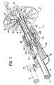
- the device object of the invention bearing the general reference 1, consists essentially of a circular plate 2 movable in rotation about an axis XX 'perpendicular to its plan through a tree motor 4.
- An energy beam F for example an ion beam, parallel to the axis XX ', can strike the targets such as 7 and 9 mounted on the supports 6 and 8 respectively. So that they can move relative to the plate, grooves such as 10 and 12 are provided along which the supports 6 and 8 can slide. In the example shown here, there are twelve grooves arranged along the radii of the plate, but this number is not imperative and any number of supports can be provided, but preferably an even number.
- the supports 6 and 8 are connected by a cable 11, one end of which is fixed to the support 6 and the other end to the support 8.
- the cable first passes through a pulley 14 mounted on a drum 18 secured to the plate 2, the plane of the pulley 14 coinciding with that defined by the axis XX 'and the groove 10.
- the cable then travels parallel to the shaft 4 before passing over a pulley 15 secured to this shaft and to return, always parallel to it, to another pulley 16 mounted on the drum 18 in the same way as the pulley 14, while its other end is fixed to the support 8.
- the barrel 20 is integral in rotation with the shaft 4, but can move in translation along the latter.
- the barrel 20 carries parallel passages associated two by two, such as the longitudinal passages 22 and 24 for the cable 11 which connects the supports 6 and 8.
- the passage 24 is equipped with two screws 26 and 28 whose role is to fix to the barrel 20 the strand of the cable corresponding to the support 8.
- the barrel is equipped with a finger 29 capable of cooperating with a groove 30, shown diagrammatically in phantom, together swam inside an intermediate piece 32 shown in section in the figure.
- the part 32 which is concentric with the shaft 4, is rotated by a second drive shaft 5 ending in a pinion 17 capable of meshing on another pinion 19 integral with said part 32.
- FIG. 2 On which a sectional view of the device has been shown, the latter being cut by two planes each containing the axis XX ', but passing the one by the groove 12 of the support 8 and the other by the groove 10 of the support 6, the two views being folded down on the same plane for greater clarity.
- the plate 2 with the grooves 10 and 12 along which move the supports 6 and 8 respectively.
- the cable 11 has two strands, the first of which passes freely through the passage 22 of the barrel 20 while the other strand 11b is fixed in the passage 24 by means of the screws 26 and 28.
- the movement of the part 32 has the effect of driving the barrel 20 longitudinally along the shaft 4 by l 'Intermediate of the finger 29 which cooperates with the groove 30.
- the barrel can come into a position 20a shown schematically in phantom in the figure while the finger 29 comes into a position 29a.
- the strand llb of the cable is fixed relative to the barrel, this movement has the effect of driving the support 8 to position 8a also shown in dashed lines, while the strand 11a moves in the opposite direction to the strand llb, letting the support 6 go to a position 6a located on the periphery of the plate.
- the supports such as 6 and 8 are constantly stressed towards the outside of the plate, by centrifugal force when the latter rotates, but other means can be used, for example springs or any equivalent system.
- each time the groove 12 passes in front of the beam F it is a different part of the target 9 placed on the support 8 which is struck by the beam since the target holder only moves, between two consecutive passages, by a relatively small fraction of the length of the groove, for example 1/5 th or less. It is also possible to introduce a slight slip at each turning point of the movement of the supports (either towards the center of the plate, or towards the periphery thereof) in order to introduce another offset during each passage of the target in front of the beam. F, which considerably reduces the probability of seeing the same portion of the target struck twice by the beam F.
- the fact that two neighboring supports such as 6 and 8 have movements in opposite directions makes it possible to reduce the bulk of the device and to place a maximum number of supports on a tray of given dimensions, but this is not compulsory.
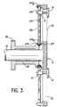
- FIG. 3 illustrates another embodiment in which the cable system is replaced by a system of the screw-nut type.
- each support 8 is associated with a rod 34 disposed parallel to the groove 12 and whose ends 34a and 34b are fixed to the plate 2 respectively towards the center and the periphery of the latter.
- the rod 34 is thus immobilized in translation but free to rotate about its axis. It comprises a double helical guide with inverted pitch 36 which cooperates with a connecting piece 38 made integral with the support 8.
- the piece 38 can only move in translation parallel to the groove 12 and always keeping the same orientation relative to that -ci, it is clear that the rotational movements of the rod 34 cause a longitudinal displacement of the connecting piece 38 along said rod 34.
- the intermediate piece 32 ends with a pinion 33 which meshes with another pinion 35 situated at the end 34a of the rod 34.
- the rotational movements of the plate 2 can be combined with the translational movements of the supports 6 and 8 along the grooves 10 and 12.
- the configuration of the groove 36 at the ends of the rod so as to introduce an offset at each turning point of the target holders.
- the invention is not limited to the two embodiments which have just been described, but that we can envisage others without departing from the scope of. the invention, the aim being to combine the rotational movements of the plate with the translational movements of the target supports along the grooves.
- a slow radial movement can be made from the center towards the periphery, followed by a rapid return.
- a simplification of the system can be made if the number of supports is chosen equal to 6 + 4n, where n is an integer: in fact, compliance with this condition makes it possible to associate two diametrically opposed supports jointly, while retaining the fact that two adjacent supports have opposite radial movements. We thus gain from the point of view of dimensioning and we divide by two the number of systems to move relative to the plate.
Abstract
Porte-cibles à balayage mécanique. Le dispositif comprend plusieurs supports de cibles (6, 8) montés sur un plateau (2) mobile en rotation autour d'un axe (XX') et des moyens de déplacement des supports par rapport au plateau (2) agencés de telle sorte que l'incrément de déplacement radial d'un support (6) entre deux passages consécutifs devant le faisceau (F) soit constant pendant la durée d'une excursion entre les deux positions extrêmes du support (6). Application à l'implantation d'ions sur une plaquette de silicium.Mechanical scanning target holders. The device comprises several target supports (6, 8) mounted on a plate (2) movable in rotation about an axis (XX ') and means for moving the supports relative to the plate (2) arranged so that the increment of radial displacement of a support (6) between two consecutive passages in front of the beam (F) is constant for the duration of an excursion between the two extreme positions of the support (6). Application to the implantation of ions on a silicon wafer.
Description
La présente invention a pour objet un porte-cibles à balayage mécanique permettant un dépôt ou une implantation homogène sur une ou plusieurs cibles montées sur le dispositif, ce dépôt ou cette implantation étant obtenu à l'aide d'une source d'énergie.The present invention relates to a target holder with mechanical scanning allowing a uniform deposit or implantation on one or more targets mounted on the device, this deposit or this implantation being obtained using an energy source.
De nombreuses applications nécessitent que des cibles soient frappées par un faisceau énergétique ou un flux de particules, par exemple l'implantation d'ions sur une plaquette de silicium destinée à la réalisation de circuits intégrés. Etant donné que le diamètre du faisceau est généralement très inférieur aux dimensions de la cible, le principal problème qui se pose dans ce genre d'application est celui de l'homogénéité de l'implantation.Many applications require that targets be struck by an energy beam or a flow of particles, for example the implantation of ions on a silicon wafer intended for the production of integrated circuits. Since the diameter of the beam is generally much smaller than the dimensions of the target, the main problem which arises in this kind of application is that of the homogeneity of the implantation.
Les différents systèmes utilisés à ce jour peuvent se classer en deux grandes catégories : les systèmes mécaniques et les systèmes électriques. Dans le cas des systèmes mécaniques, les cibles sont montées sur un support qui se déplace devant le faisceau qui, lui, est fixe. Le déplacement du support s'effectue selon deux mouvements croisés : un mouvement dit lent et un mouvement dit rapide, perpendiculaire au mouvement dit lent. Dans l'art antérieur, pour la réalisation du mouvement rapide, les cibles peuvent par exemple être placées sur un tambour tournant autour d'un axe perpendiculaire au faisceau ou montées sur un support déformable entraîné par deux roues motrices. Il existe encore un système dans lequel les cibles placées sur un tambour gardent constamment la même orientation, c'est-à-dire restent parallèles à elles- mêmes et donc perpendiculaires au faisceau. Le mouvement lent dans les cas précédents est un mouvement de translation alterné dans une direction parallèle aux axes de rotation.The various systems used to date can be classified into two main categories: mechanical systems and electrical systems. In the case of mechanical systems, the targets are mounted on a support which moves in front of the beam which is itself fixed. The support is moved in two crossed movements: a so-called slow movement and a so-called fast movement, perpendicular to the so-called slow movement. In the prior art, for carrying out the rapid movement, the targets can for example be placed on a drum rotating around an axis perpendicular to the beam or mounted on a deformable support driven by two driving wheels. There is also a system in which the targets placed on a drum constantly keep the same orientation, that is to say remain parallel to themselves and therefore perpendicular to the beam. The slow movement in the previous cases is an alternating translational movement in a direction parallel to the axes of rotation.
Le principal inconvénient de ces dispositifs est que les mouvements sont lents et que le risque d'inhomogénéité d'implantation est grand à cause des variations d'intensité du faisceau malgré le mouvement de va-et-vient qui se superpose au mouvement de rotation. D'autre part, les mouvements des cibles peuvent être tels que l'orientation de ces dernières par rapport au faisceau est variable et l'angle d'incidence n'est pas le même en tous les points de la cible. Si ces défauts n'ont guère d'importance lorsque les plaques sont de petites dimensions, ils deviennent prohibitifs lorsque la taille de celles-ci augmente, car les conditions d'impact peuvent varier de manière importante d'un point à un autre.The main drawback of these devices is that the movements are slow and that the risk of non-uniformity of implantation is great because of variations in intensity of the beam despite the back-and-forth movement which is superimposed on the rotational movement. On the other hand, the movements of the targets can be such that the orientation of the latter relative to the beam is variable and the angle of incidence is not the same at all the points of the target. If these defects have little importance when the plates are small, they become prohibitive when the size of these increases, since the impact conditions can vary significantly from one point to another.
Une autre catégorie de dispositifs utilise des plateaux sur lesquels sont montées les cibles, l'axe de rotation du plateau étant parallèle au faisceau. Le mouvement rapide est dans ce cas la rotation, le mouvement lent étant réalisé par un déplacement, parallèlement à lui-même, de l'axe de rotation du plateau, dans un plan passant par l'axe du faisceau. Ce dispositif présente l'avantage que l'angle d'incidence du faisceau sur la cible est constant. Mais il présente l'inconvénient que le rayon de la trajectoire du faisceau sur la cible est variable. Les traces ne sont pas parallèles et si la vitesse de rotation est constante, la vitesse linéaire relative du faisceau et de la cible est variable et dépend de la distance faisceau-axe de rotation. Ceci implique la nécessité de systèmes de contre-réaction sur la vitesse.lente de façon à obtenir une bonne homogénéité sur la cible.Another category of devices uses plates on which the targets are mounted, the axis of rotation of the plate being parallel to the beam. In this case, the rapid movement is rotation, the slow movement being produced by a displacement, parallel to itself, of the axis of rotation of the plate, in a plane passing through the axis of the beam. This device has the advantage that the angle of incidence of the beam on the target is constant. However, it has the drawback that the radius of the path of the beam on the target is variable. The traces are not parallel and if the speed of rotation is constant, the relative linear speed of the beam and the target is variable and depends on the distance beam-axis of rotation. This implies the need for slow speed feedback systems in order to obtain good homogeneity on the target.
Dans les systèmes électriques, les cibles sont fixes, mais on réalise un balayage en faisant varier la direction du faisceau d'ions. Etant donné que les angles de déflexion augmentent avec la dimension des plaques, ceci entraîne des inhomogénéités d'implantation malgré les corrections électroniques apportées sur le temps de balayage.In electrical systems, the targets are fixed, but a scan is carried out by varying the direction of the ion beam. Given as the deflection angles increase with the size of the plates, this leads to implantation inhomogeneities despite the electronic corrections made over the scanning time.
La présente invention a justement pour objet de remédier à ces inconvénients en proposant un porte-cibles à balayage mécanique qui permette d'obtenir une excellente homogénéité d'implantation sur les cibles.The object of the present invention is precisely to remedy these drawbacks by proposing a target holder with mechanical scanning which makes it possible to obtain excellent homogeneity of implantation on the targets.
Selon la principale caractéristique du porte-cibles objet de l'invention, celui-ci, du type comportant plusieurs supports de cibles montés sur un plateau mobile en rotation par rapport à un axe afin que lesdits supports passent à tour de rôle devant un faisceau énergétique fixe par rapport à l'axe de rotation du plateau, se caractérise en ce qu'il comporte des moyens permettant de déplacer chaque support par rapport au plateau, l'agencement desdits moyens de déplacement étant tel que l'incrément de déplacement radial d'un support entre deux instants correspondant à deux passages consécutifs du support devant le faisceau soit constant pendant la durée d'une excursion entre les positions extrêmes et tel que le support aie toujours la même orientation par rapport au plateau à chaque passage devant le faisceau.According to the main characteristic of the target holder object of the invention, it, of the type comprising several target supports mounted on a plate movable in rotation relative to an axis so that said supports pass in turn in front of an energy beam fixed relative to the axis of rotation of the plate, is characterized in that it comprises means making it possible to move each support relative to the plate, the arrangement of said displacement means being such that the increment of radial displacement of a support between two instants corresponding to two consecutive passages of the support in front of the beam is constant for the duration of an excursion between the extreme positions and such that the support always has the same orientation relative to the plate at each passage in front of the beam.
Le mouvement des supports est un mouvement de va-et-vient, de préférence suivant une direction radiale : dans ce cas, deux supports différents se déplacent suivant deux rayons différents du plateau et deux supports adjacents se déplacent en sens opposé. Dans la présente invention, le plateau mobile en rotation peut être remplacé par toute autre pièce mécanique de forme différente, pourvu que l'agencement des moyens de déplacement permette d'obtenir le même résultat. La présente invention est caractérisée par des conditions à respecter sur l'incrément de déplacement radial des supports par rapport au plateau. Il est à remarquer que ceci n'implique en rien que le déplacement soit uniquement radial et en outre n'implique pas de conditions sur la cinématique des supports entre deux passages consécutifs devant le faisceau. La position et l'orientation des supports doivent respecter des règles bien précises uniquement aux instants correspondant au passage devant le faisceau. La seule condition à respecter est que l'incrément de déplacement radial soit constant entre deux passages consécutifs devant le faisceau et il n'y a aucune condition particulière sur les autres composantes du déplacement.The movement of the supports is a back-and-forth movement, preferably in a radial direction: in this case, two different supports move along two different radii of the plate and two adjacent supports move in the opposite direction. In the present invention, the rotating mobile plate can be replaced by any other mechanical part of different shape, provided that the arrangement of the displacement means makes it possible to obtain the same result. The present invention is characterized by conditions to be observed on the increment of radial displacement of the supports relative to the plate. He is at note that this in no way implies that the displacement is only radial and furthermore does not imply conditions on the kinematics of the supports between two consecutive passages in front of the beam. The position and orientation of the supports must comply with very specific rules only at the times corresponding to the passage in front of the beam. The only condition to be respected is that the increment of radial displacement is constant between two consecutive passages in front of the beam and there are no particular conditions on the other components of displacement.
Suivant un premier mode de réalisation de l'invention, les moyens permettant de déplacer chaque support par rapport au plateau comprennent :
- une rainure radiale le long de laquelle le support peut coulisser,
- - un premier arbre moteur servant à entraîner le plateau en rotation, et
- - un câble reliant deux supports adjacents et passant sur au moins une poulie solidaire de l'arbre..
- a radial groove along which the support can slide,
- a first motor shaft used to drive the plate in rotation, and
- - a cable connecting two adjacent supports and passing over at least one pulley secured to the shaft.
Selon une autre caractéristique de ce premier mode de réalisation, les moyens permettant de déplacer chaque support par rapport au plateau comprennent un barillet monté sur l'arbre, immobilisé en rotation mais libre en translation par rapport à ce dernier, le barillet étant équipé d'un doigt apte à coopérer avec une rainure ménagée dans une pièce intermédiaire pouvant tourner autour du même axe que l'arbre, les vitesses de rotation de l'arbre et de la pièce étant généralement différentes.According to another characteristic of this first embodiment, the means making it possible to move each support relative to the plate comprise a barrel mounted on the shaft, immobilized in rotation but free in translation relative to the latter, the barrel being equipped with a finger able to cooperate with a groove formed in an intermediate part which can rotate about the same axis as the shaft, the speeds of rotation of the shaft and of the part being generally different.
Dans ce cas, le barillet comporte avantageusement au moins deux passages pour un câble reliant deux supports adjacents, l'un des deux passages étant équipé de moyens permettant de fixer par rapport au barillet l'un des brins du câble.In this case, the barrel advantageously comprises at least two passages for a cable connecting two adjacent supports, one of the two passages being equipped with means making it possible to fix relative to the barrel one of the strands of the cable.
Dans un deuxième mode de réalisation, les moyens permettant de déplacer chaque support par rapport au plateau comprennent :
- - une rainure radiale le long de laquelle le support peut coulisser,
- - une tige cylindrique munie d'une rainure de guidage hélicoïdale, disposée parallèlement à la rainure précitée et ayant ses extrémités fixées par rapport au plateau, la tige étant libre en rotation, et
- - une pièce de liaison solidaire du support et de la tige, ladite pièce de liaison étant immobilisée en rotation mais libre en translation par rapport à la tige.
- - a radial groove along which the support can slide,
- a cylindrical rod provided with a helical guide groove, arranged parallel to the aforementioned groove and having its ends fixed relative to the plate, the rod being free to rotate, and
- - A connecting piece secured to the support and the rod, said connecting piece being immobilized in rotation but free in translation relative to the rod.
Enfin, selon une autre caractéristique de ce deuxième mode de réalisation, les moyens permettant de déplacer chaque support par rapport au plateau comprennent en outre une pièce intermédiaire équipée d'un pignon apte à coopérer avec un autre pignon disposé à une extrémité de la tige.Finally, according to another characteristic of this second embodiment, the means making it possible to move each support relative to the plate further comprise an intermediate piece equipped with a pinion capable of cooperating with another pinion disposed at one end of the rod.
L'invention apparaîtra mieux à la lecture de la description qui va suivre, donnée à titre purement illustratif et nullement limitatif, en référence aux dessins annexés, dans lesquels :
- - la figure 1 est une vue schématique en perspective et partiellement en coupe d'un premier mode de réalisation du porte-cibles selon l'invention ;
- - la figure 2 est une vue schématique en coupe représentant les moyens de déplacement de deux supports de cibles adjacents, rabattus sur un même plan ; et
- - la figure 3 est une vue schématique en coupe illustrant un deuxième mode de réalisation du porte-cibles selon l'invention.
- - Figure 1 is a schematic perspective view and partially in section of a first embodiment of the target holder according to the invention;
- - Figure 2 is a schematic sectional view showing the means of movement of two adjacent target supports, folded on the same plane; and
- - Figure 3 is a schematic sectional view illustrating a second embodiment of the target holder according to the invention.
Si l'on se reporte à la figure 1, on voit que le dispositif objet de l'invention, portant la référence générale 1, se compose essentiellement d'un plateau circulaire 2 mobile en rotation autour d'un axe XX' perpendiculaire à son plan grâce à un arbre moteur 4. Un faisceau énergétique F, par exemple un faisceau d'ions, parallèle à l'axe XX', peut frapper les cibles telles que 7 et 9 montées sur les supports 6 et 8 respectivement. Afin que ceux-ci puissent se déplacer par rapport au plateau, on a prévu des rainures telles que 10 et 12 le long desquelles les supports 6 et 8 peuvent coulisser. Dans l'exemple représenté ici, il y a douze rainures disposées suivant des rayons du plateau mais ce nombre n'est pas impératif et l'on peut prévoir un nombre quelconque de supports, mais de préférence un nombre pair. On voit encore sur la figure que les supports 6 et 8 sont reliés par un câble 11 dont une première extrémité est fixée au support 6 et l'autre extrémité au support 8. Partant du support 6, le câble passe tout d'abord dans une poulie 14 montée sur un tambour 18 solidaire du plateau 2, le plan de la poulie 14 étant confondu avec celui défini par l'axe XX' et la rainure 10. Le câble chemine ensuite parallèlement à l'arbre 4 avant de passer sur une poulie 15 solidaire de cet arbre et de revenir, toujours parallèlement- à ce dernier, jusqu'à une autre poulie 16 montée sur le tambour 18 de la même façon que la poulie 14, tandis que son autre extrémité est fixée au support 8. On voit encore sur la figure 1 un barillet 20 monté sur l'arbre 4 : le barillet 20 est solidaire en rotation de l'arbre 4, mais peut se déplacer en translation le long de celui-ci. Le barillet 20 porte des passages parallèles associés deux par deux, tels que les passages longitudinaux 22 et 24 pour le câble 11 qui relie les supports 6 et 8. Le passage 24 est équipé de deux vis 26 et 28 dont le rôle est de fixer au barillet 20 le brin du câble correspondant au support 8. D'autre part, le barillet est équipé d'un doigt 29 apte à coopérer avec une rainure 30, représentée schématiquement en traits mixtes, ménagée à l'intérieur d'une pièce intermédiaire 32 représentée en coupe sur la figure. La pièce 32, qui est concentrique à l'arbre 4, est entraînée en rotation par un deuxième arbre moteur 5 se terminant par un pignon 17 apte à engrener sur un autre pignon 19 solidaire de ladite pièce 32.If we refer to Figure 1, we see that the device object of the invention, bearing the general reference 1, consists essentially of a circular plate 2 movable in rotation about an axis XX 'perpendicular to its plan through a
On va maintenant décrire le fonctionnement de l'appareil à l'aide de la figure 2 sur laquelle on a représenté une vue en coupe du dispositif, celui-ci étant coupé par deux plans contenant chacun l'axe XX', mais passant l'un par la rainure 12 du support 8 et l'autre par la rainure 10 du support 6, les deux vues étant rabattues sur un même plan pour plus de clarté. On retrouve donc sur la figure 2 le plateau 2 avec les rainures 10 et 12 le long desquelles se déplacent les supports 6 et 8 respectivement. On voit aussi que le câble 11 comporte deux brins dont le premier lla passe librement dans le passage 22 du barillet 20 tandis que l'autre brin llb est fixé dans le passage 24 à l'aide des vis 26 et 28.We will now describe the operation of the apparatus using FIG. 2 on which a sectional view of the device has been shown, the latter being cut by two planes each containing the axis XX ', but passing the one by the
Etant donné que l'arbre 4 et la pièce intermédiaire 32 tournent autour de l'axe XX' avec des vitesses différentes, le mouvement de la pièce 32 a pour effet d'entraîner le barillet 20 longitudinalement le long de l'arbre 4 par l'intermédiaire du doigt 29 qui coopère avec la rainure 30. C'est ainsi que le barillet peut venir en une position 20a représentée schématiquement en traits mixtes sur la figure tandis que le doigt 29 vient en une position 29a. Puisque le brin llb du câble est fixe par rapport au barillet, ce mouvement a pour effet d'entraîner le support 8 jusqu'à la position 8a représentée également en traits mixtes, tandis que le brin lla se déplace en sens inverse du brin llb, laissant le support 6 aller jusqu'à une position 6a située à la périphérie du plateau. Dans l'exemple décrit ici, les supports tels que 6 et 8 sont constamment sollicités vers l'extérieur du plateau, par la force centrifuge lorsque ce dernier tourne, mais on peut utiliser d'autres moyens, par exemple des ressorts ou n'importe quel système équivalent.Since the
On voit donc qu'en agissant sur les vitesses de rotation de l'arbre 4 et de la pièce 32,ainsi que sur la forme de la rainure 30, on peut obtenir toutes les combinaisons possibles entre le mouvement de rotation du plateau et les mouvements de translation des supports le long des rainures correspondantes. A titre d'exemple, on a réalisé un tel dispositif dans lequel il faut cinq tours du plateau pour qu'un support fasse un trajet simple entre les points extrêmes de la rainure correspondante. On voit encore sur la figure 2 que le faisceau F frappe le plateau en un point situé sensiblement au milieu de la rainure 12. Ainsi, à chaque passage de la rainure 12 devant le faisceau F, c'est une partie différente de la cible 9 placée sur le support 8 qui est frappée par le faisceau puisque le porte-cible ne se déplace, entre deux passages consécutifs, que d'une fraction relativement faible de la longueur de la rainure, par exemple 1/5e ou moins. On peut encore introduire un léger glissement à chaque point de rebroussement du mouvement des supports (soit vers le centre du plateau, soit vers la périphérie de celui-ci) afin d'introduire un autre décalage lors de chaque passage de la cible devant le faisceau F, ce qui réduit considérablement la probabilité de voir la même portion de la cible frappée deux fois par le faisceau F. Le fait que deux supports voisins tels que 6 et 8 aient des mouvements en sens inverse permet de réduire l'encombrement du dispositif et de placer un nombre maximal de supports sur un plateau de dimensions données, mais ceci n'est pas obligatoire.It can therefore be seen that by acting on the speeds of rotation of the
La figure 3 illustre un autre mode de réalisation dans lequel le système de câbles est remplacé par un système du genre vis-écrou. On voit qu'à chaque support 8 est associée une tige 34 disposée parallèlement à la rainure 12 et dont les extrémités 34a et 34b sont fixées au plateau 2 respectivement vers le centre et la périphérie de ce dernier. La tige 34 est ainsi immobilisée en translation mais libre en rotation autour de son axe. Elle comporte un guidage hélicoïdal double à pas inversé 36 qui coopère avec une pièce de liaison 38 rendue solidaire du support 8. La pièce 38 ne pouvant se déplacer qu'en translation parallèlement à la rainure 12 et gardant toujours la même orientation par rapport à celle-ci, il est clair que les mouvements de rotation de la tige 34 entraînent un déplacement longitudinal de la pièce de liaison 38 le long de ladite tige 34. Dans l'exemple particulier illustré à la figure 3, on voit que la pièce intermédiaire 32 se termine par un pignon 33 qui engrène sur un autre pignon 35 situé à l'extrémité 34a de la tige 34. Là encore, en agissant sur les vitesses de rotation de l'arbre 4 et de la pièce 32, et en choisissant convenablement le dessin des rainures de guidage 36 qui équipent la tige 34, on peut combiner les mouvements de rotation du plateau 2 avec les mouvements de translation des supports 6 et 8 le long des rainures 10 et 12. De plus, on peut choisir la configuration de la rainure 36 aux extrémités de la tige de manière à introduire un décalage à chaque point de rebroussement des porte-cibles.FIG. 3 illustrates another embodiment in which the cable system is replaced by a system of the screw-nut type. We see that each support 8 is associated with a
Le dispositif selon l'invention présente des avantages particulièrement intéressants, dont le principal est qu'il permet d'obtenir une bonne homogénéité puisque les caractéristiques suivantes sont respectées :
- - les trajectoires relatives du faisceau et de chaque cible sont à rayon constant puisque la distance entre le faisceau F et l'axe de rotation du plateau est constante, donc le balayage se fait à vitesse linéaire constante si la vitesse de rotation du plateau est constante ;
- - l'écart entre 2 trajectoires consécutives est constant ;
- - en outre il suffit que la vitesse de rotation soit constante, ou peu variable, pendant la durée d'une excursion radiale pour que la condition d'homogénéité soit respectée. De plus, grâce au décalage que l'on introduit à chaque rebroussement, aucune des trajectoires du faisceau sur les cibles n'en recouvre exactement une autre.
- - the relative trajectories of the beam and of each target are at constant radius since the distance between the beam F and the axis of rotation of the plate is constant, therefore the scanning is done at constant linear speed if the speed of rotation of the plate is constant ;
- - the difference between 2 consecutive trajectories is constant;
- - In addition, it is sufficient that the speed of rotation is constant, or not very variable, during the duration of a radial excursion for the condition of homogeneity to be respected. In addition, thanks to the offset that is introduced at each cusp, none of the beam trajectories on the targets exactly overlaps another.
Il est bien entendu que l'invention ne se limite pas aux deux modes de réalisation qui viennent d'être décrits, mais qu'on peut en envisager d'autres sans sortir pour autant du cadre de. l'invention, le but étant de combiner les mouvements de rotation du plateau avec les mouvements de translation des supports de cible le long des rainures. En particulier il est possible de choisir une vitesse radiale des supports de cibles différente pour chacun des 2 sens de déplacement radial des supports. Ainsi par exemple, on peut réaliser un mouvement radial lent du centre vers la périphérie, suivi d'un retour rapide. Pour cela, il suffit, dans le premier mode de réalisation, de donner à la rainure 30 la forme d'une double hélice à pas opposés et de valeurs différentes.It is understood that the invention is not limited to the two embodiments which have just been described, but that we can envisage others without departing from the scope of. the invention, the aim being to combine the rotational movements of the plate with the translational movements of the target supports along the grooves. In particular, it is possible to choose a different radial speed of the target supports for each of the 2 directions of radial displacement of the supports. Thus, for example, a slow radial movement can be made from the center towards the periphery, followed by a rapid return. For this, it suffices, in the first embodiment, to give the
Une simplification du système peut être apportée si le nombre des supports est choisi égal à 6 + 4n, où n est un nombre entier : en effet, le respect de cette condition permet d'associer solidairement deux supports diamétralement opposés, tout en conservant le fait que deux supports adjacents ont des mouvements radiaux opposés. On gagne ainsi au point de vue du dimensionnement et on divise par deux le nombre de systèmes à déplacer par rapport au plateau.A simplification of the system can be made if the number of supports is chosen equal to 6 + 4n, where n is an integer: in fact, compliance with this condition makes it possible to associate two diametrically opposed supports jointly, while retaining the fact that two adjacent supports have opposite radial movements. We thus gain from the point of view of dimensioning and we divide by two the number of systems to move relative to the plate.
Claims (12)
Applications Claiming Priority (2)
| Application Number | Priority Date | Filing Date | Title |
|---|---|---|---|
| FR8211077A FR2529383A1 (en) | 1982-06-24 | 1982-06-24 | MECHANICAL SCANNING TARGET HOLDER USABLE IN PARTICULAR FOR THE IMPLANTATION OF IORIS |
| FR8211077 | 1982-06-24 |
Publications (1)
| Publication Number | Publication Date |
|---|---|
| EP0099778A1 true EP0099778A1 (en) | 1984-02-01 |
Family
ID=9275361
Family Applications (1)
| Application Number | Title | Priority Date | Filing Date |
|---|---|---|---|
| EP83401282A Withdrawn EP0099778A1 (en) | 1982-06-24 | 1983-06-21 | Mechanically scanned target holder |
Country Status (4)
| Country | Link |
|---|---|
| US (1) | US4508056A (en) |
| EP (1) | EP0099778A1 (en) |
| JP (1) | JPS5946750A (en) |
| FR (1) | FR2529383A1 (en) |
Cited By (10)
| Publication number | Priority date | Publication date | Assignee | Title |
|---|---|---|---|---|
| EP0136610A2 (en) * | 1983-09-30 | 1985-04-10 | Siemens Aktiengesellschaft | Samples holder for secondary ion mass spectroscopy (SIMS) and other high accuracy methods of analyzing particle rays, and method of operating it |
| WO1991006972A1 (en) * | 1989-10-27 | 1991-05-16 | Superion Limited | Method and apparatus relating to ion implantation |
| GB2274196A (en) * | 1993-01-06 | 1994-07-13 | Kore Tech Ltd | Manipulating a sample |
| US5985742A (en) * | 1997-05-12 | 1999-11-16 | Silicon Genesis Corporation | Controlled cleavage process and device for patterned films |
| US6027988A (en) * | 1997-05-28 | 2000-02-22 | The Regents Of The University Of California | Method of separating films from bulk substrates by plasma immersion ion implantation |
| US6263941B1 (en) | 1999-08-10 | 2001-07-24 | Silicon Genesis Corporation | Nozzle for cleaving substrates |
| US6284631B1 (en) | 1997-05-12 | 2001-09-04 | Silicon Genesis Corporation | Method and device for controlled cleaving process |
| US6291313B1 (en) | 1997-05-12 | 2001-09-18 | Silicon Genesis Corporation | Method and device for controlled cleaving process |
| US8993410B2 (en) | 2006-09-08 | 2015-03-31 | Silicon Genesis Corporation | Substrate cleaving under controlled stress conditions |
| US9362439B2 (en) | 2008-05-07 | 2016-06-07 | Silicon Genesis Corporation | Layer transfer of films utilizing controlled shear region |
Families Citing this family (35)
| Publication number | Priority date | Publication date | Assignee | Title |
|---|---|---|---|---|
| JPS61202426A (en) * | 1985-03-05 | 1986-09-08 | Matsushita Electric Ind Co Ltd | Manufacture of semiconductor device |
| JP2582552B2 (en) * | 1986-05-29 | 1997-02-19 | 三菱電機株式会社 | Ion implanter |
| US4771012A (en) * | 1986-06-13 | 1988-09-13 | Matsushita Electric Industrial Co., Ltd. | Method of making symmetrically controlled implanted regions using rotational angle of the substrate |
| USRE35036E (en) * | 1986-06-13 | 1995-09-12 | Matsushita Electric Industrial Co., Ltd. | Method of making symmetrically controlled implanted regions using rotational angle of the substrate |
| US4816133A (en) * | 1987-05-14 | 1989-03-28 | Northrop Corporation | Apparatus for preparing thin film optical coatings on substrates |
| US4975586A (en) * | 1989-02-28 | 1990-12-04 | Eaton Corporation | Ion implanter end station |
| FR2681472B1 (en) | 1991-09-18 | 1993-10-29 | Commissariat Energie Atomique | PROCESS FOR PRODUCING THIN FILMS OF SEMICONDUCTOR MATERIAL. |
| FR2748851B1 (en) * | 1996-05-15 | 1998-08-07 | Commissariat Energie Atomique | PROCESS FOR PRODUCING A THIN FILM OF SEMICONDUCTOR MATERIAL |
| US20070122997A1 (en) | 1998-02-19 | 2007-05-31 | Silicon Genesis Corporation | Controlled process and resulting device |
| US6548382B1 (en) | 1997-07-18 | 2003-04-15 | Silicon Genesis Corporation | Gettering technique for wafers made using a controlled cleaving process |
| FR2773261B1 (en) | 1997-12-30 | 2000-01-28 | Commissariat Energie Atomique | METHOD FOR THE TRANSFER OF A THIN FILM COMPRISING A STEP OF CREATING INCLUSIONS |
| JP2891255B1 (en) * | 1998-04-15 | 1999-05-17 | 日本電気株式会社 | Ion implanter |
| US6291326B1 (en) | 1998-06-23 | 2001-09-18 | Silicon Genesis Corporation | Pre-semiconductor process implant and post-process film separation |
| US6221740B1 (en) | 1999-08-10 | 2001-04-24 | Silicon Genesis Corporation | Substrate cleaving tool and method |
| EP1212787B1 (en) * | 1999-08-10 | 2014-10-08 | Silicon Genesis Corporation | A cleaving process to fabricate multilayered substrates using low implantation doses |
| US6500732B1 (en) | 1999-08-10 | 2002-12-31 | Silicon Genesis Corporation | Cleaving process to fabricate multilayered substrates using low implantation doses |
| US6485616B1 (en) * | 1999-12-29 | 2002-11-26 | Deposition Sciences, Inc. | System and method for coating substrates with improved capacity and uniformity |
| FR2823599B1 (en) | 2001-04-13 | 2004-12-17 | Commissariat Energie Atomique | DEMOMTABLE SUBSTRATE WITH CONTROLLED MECHANICAL HOLDING AND METHOD OF MAKING |
| US8187377B2 (en) * | 2002-10-04 | 2012-05-29 | Silicon Genesis Corporation | Non-contact etch annealing of strained layers |
| FR2848336B1 (en) * | 2002-12-09 | 2005-10-28 | Commissariat Energie Atomique | METHOD FOR PRODUCING A STRESS STRUCTURE FOR DISSOCIATING |
| FR2856844B1 (en) * | 2003-06-24 | 2006-02-17 | Commissariat Energie Atomique | HIGH PERFORMANCE CHIP INTEGRATED CIRCUIT |
| FR2857953B1 (en) | 2003-07-21 | 2006-01-13 | Commissariat Energie Atomique | STACKED STRUCTURE, AND METHOD FOR MANUFACTURING THE SAME |
| FR2861497B1 (en) * | 2003-10-28 | 2006-02-10 | Soitec Silicon On Insulator | METHOD FOR CATASTROPHIC TRANSFER OF A FINE LAYER AFTER CO-IMPLANTATION |
| US7354815B2 (en) * | 2003-11-18 | 2008-04-08 | Silicon Genesis Corporation | Method for fabricating semiconductor devices using strained silicon bearing material |
| FR2889887B1 (en) * | 2005-08-16 | 2007-11-09 | Commissariat Energie Atomique | METHOD FOR DEFERING A THIN LAYER ON A SUPPORT |
| US8293619B2 (en) | 2008-08-28 | 2012-10-23 | Silicon Genesis Corporation | Layer transfer of films utilizing controlled propagation |
| US7811900B2 (en) | 2006-09-08 | 2010-10-12 | Silicon Genesis Corporation | Method and structure for fabricating solar cells using a thick layer transfer process |
| FR2910179B1 (en) * | 2006-12-19 | 2009-03-13 | Commissariat Energie Atomique | METHOD FOR MANUFACTURING THIN LAYERS OF GaN BY IMPLANTATION AND RECYCLING OF A STARTING SUBSTRATE |
| FR2922359B1 (en) * | 2007-10-12 | 2009-12-18 | Commissariat Energie Atomique | METHOD FOR MANUFACTURING A MICROELECTRONIC STRUCTURE INVOLVING MOLECULAR COLLAGE |
| FR2925221B1 (en) * | 2007-12-17 | 2010-02-19 | Commissariat Energie Atomique | METHOD FOR TRANSFERRING A THIN LAYER |
| US8330126B2 (en) | 2008-08-25 | 2012-12-11 | Silicon Genesis Corporation | Race track configuration and method for wafering silicon solar substrates |
| US8329557B2 (en) | 2009-05-13 | 2012-12-11 | Silicon Genesis Corporation | Techniques for forming thin films by implantation with reduced channeling |
| FR2947098A1 (en) * | 2009-06-18 | 2010-12-24 | Commissariat Energie Atomique | METHOD OF TRANSFERRING A THIN LAYER TO A TARGET SUBSTRATE HAVING A THERMAL EXPANSION COEFFICIENT DIFFERENT FROM THAT OF THE THIN LAYER |
| FR2978600B1 (en) | 2011-07-25 | 2014-02-07 | Soitec Silicon On Insulator | METHOD AND DEVICE FOR MANUFACTURING LAYER OF SEMICONDUCTOR MATERIAL |
| US20220081757A1 (en) * | 2020-09-11 | 2022-03-17 | Tokyo Electron Limited | Film forming apparatus, film forming system, and film forming method |
Citations (4)
| Publication number | Priority date | Publication date | Assignee | Title |
|---|---|---|---|---|
| FR2298880A1 (en) * | 1975-01-22 | 1976-08-20 | Commissariat Energie Atomique | IONIC IMPLANTATION METHOD AND DEVICE |
| US3993909A (en) * | 1973-03-16 | 1976-11-23 | U.S. Philips Corporation | Substrate holder for etching thin films |
| US4274004A (en) * | 1979-02-02 | 1981-06-16 | Hitachi, Ltd. | Ion implanter |
| DE3114466A1 (en) * | 1980-04-11 | 1982-03-11 | Hitachi, Ltd., Tokyo | SYSTEM FOR DRIVING A ROTATING LINK IN A VACUUM |
Family Cites Families (3)
| Publication number | Priority date | Publication date | Assignee | Title |
|---|---|---|---|---|
| US2821158A (en) * | 1954-10-22 | 1958-01-28 | Gen Electric | Machine for coating bell-shaped electrical suspension insulators |
| US3858547A (en) * | 1973-12-14 | 1975-01-07 | Nils H Bergfelt | Coating machine having an adjustable rotation system |
| JPS57101327A (en) * | 1980-12-16 | 1982-06-23 | Nisshin Haiboruteeji Kk | Wafer carrier in ion implanting device |
-
1982
- 1982-06-24 FR FR8211077A patent/FR2529383A1/en active Granted
-
1983
- 1983-06-16 US US06/504,875 patent/US4508056A/en not_active Expired - Fee Related
- 1983-06-21 EP EP83401282A patent/EP0099778A1/en not_active Withdrawn
- 1983-06-24 JP JP58114146A patent/JPS5946750A/en active Pending
Patent Citations (4)
| Publication number | Priority date | Publication date | Assignee | Title |
|---|---|---|---|---|
| US3993909A (en) * | 1973-03-16 | 1976-11-23 | U.S. Philips Corporation | Substrate holder for etching thin films |
| FR2298880A1 (en) * | 1975-01-22 | 1976-08-20 | Commissariat Energie Atomique | IONIC IMPLANTATION METHOD AND DEVICE |
| US4274004A (en) * | 1979-02-02 | 1981-06-16 | Hitachi, Ltd. | Ion implanter |
| DE3114466A1 (en) * | 1980-04-11 | 1982-03-11 | Hitachi, Ltd., Tokyo | SYSTEM FOR DRIVING A ROTATING LINK IN A VACUUM |
Cited By (26)
| Publication number | Priority date | Publication date | Assignee | Title |
|---|---|---|---|---|
| EP0136610A2 (en) * | 1983-09-30 | 1985-04-10 | Siemens Aktiengesellschaft | Samples holder for secondary ion mass spectroscopy (SIMS) and other high accuracy methods of analyzing particle rays, and method of operating it |
| EP0136610A3 (en) * | 1983-09-30 | 1986-08-13 | Siemens Aktiengesellschaft | Samples holder for secondary ion mass spectroscopy (sims) and other high accuracy methods of analyzing particle rays, and method of operating it |
| WO1991006972A1 (en) * | 1989-10-27 | 1991-05-16 | Superion Limited | Method and apparatus relating to ion implantation |
| US5194748A (en) * | 1989-10-27 | 1993-03-16 | Superion Limited | Method and apparatus relating to ion implantation |
| GB2274196A (en) * | 1993-01-06 | 1994-07-13 | Kore Tech Ltd | Manipulating a sample |
| US6162705A (en) | 1997-05-12 | 2000-12-19 | Silicon Genesis Corporation | Controlled cleavage process and resulting device using beta annealing |
| US6284631B1 (en) | 1997-05-12 | 2001-09-04 | Silicon Genesis Corporation | Method and device for controlled cleaving process |
| US6013563A (en) * | 1997-05-12 | 2000-01-11 | Silicon Genesis Corporation | Controlled cleaning process |
| US6558802B1 (en) | 1997-05-12 | 2003-05-06 | Silicon Genesis Corporation | Silicon-on-silicon hybrid wafer assembly |
| US6048411A (en) * | 1997-05-12 | 2000-04-11 | Silicon Genesis Corporation | Silicon-on-silicon hybrid wafer assembly |
| US6155909A (en) | 1997-05-12 | 2000-12-05 | Silicon Genesis Corporation | Controlled cleavage system using pressurized fluid |
| US6159825A (en) | 1997-05-12 | 2000-12-12 | Silicon Genesis Corporation | Controlled cleavage thin film separation process using a reusable substrate |
| US5985742A (en) * | 1997-05-12 | 1999-11-16 | Silicon Genesis Corporation | Controlled cleavage process and device for patterned films |
| US6187110B1 (en) | 1997-05-12 | 2001-02-13 | Silicon Genesis Corporation | Device for patterned films |
| US6245161B1 (en) | 1997-05-12 | 2001-06-12 | Silicon Genesis Corporation | Economical silicon-on-silicon hybrid wafer assembly |
| US6511899B1 (en) | 1997-05-12 | 2003-01-28 | Silicon Genesis Corporation | Controlled cleavage process using pressurized fluid |
| US6010579A (en) * | 1997-05-12 | 2000-01-04 | Silicon Genesis Corporation | Reusable substrate for thin film separation |
| US6290804B1 (en) | 1997-05-12 | 2001-09-18 | Silicon Genesis Corporation | Controlled cleavage process using patterning |
| US6291313B1 (en) | 1997-05-12 | 2001-09-18 | Silicon Genesis Corporation | Method and device for controlled cleaving process |
| US6027988A (en) * | 1997-05-28 | 2000-02-22 | The Regents Of The University Of California | Method of separating films from bulk substrates by plasma immersion ion implantation |
| US6263941B1 (en) | 1999-08-10 | 2001-07-24 | Silicon Genesis Corporation | Nozzle for cleaving substrates |
| US8993410B2 (en) | 2006-09-08 | 2015-03-31 | Silicon Genesis Corporation | Substrate cleaving under controlled stress conditions |
| US9356181B2 (en) | 2006-09-08 | 2016-05-31 | Silicon Genesis Corporation | Substrate cleaving under controlled stress conditions |
| US9640711B2 (en) | 2006-09-08 | 2017-05-02 | Silicon Genesis Corporation | Substrate cleaving under controlled stress conditions |
| US9362439B2 (en) | 2008-05-07 | 2016-06-07 | Silicon Genesis Corporation | Layer transfer of films utilizing controlled shear region |
| US11444221B2 (en) | 2008-05-07 | 2022-09-13 | Silicon Genesis Corporation | Layer transfer of films utilizing controlled shear region |
Also Published As
| Publication number | Publication date |
|---|---|
| FR2529383B1 (en) | 1985-05-10 |
| US4508056A (en) | 1985-04-02 |
| FR2529383A1 (en) | 1983-12-30 |
| JPS5946750A (en) | 1984-03-16 |
Similar Documents
| Publication | Publication Date | Title |
|---|---|---|
| EP0099778A1 (en) | Mechanically scanned target holder | |
| EP0076268B1 (en) | Automatic manipulator | |
| EP0371896B1 (en) | Device for marking by micro-percussion | |
| FR2715005A1 (en) | Electric collector rotating with multi-strand brushes. | |
| EP0634986B1 (en) | Translational/rotational support member conveying system | |
| EP0205376A1 (en) | Robot wrist and robot equipped with such a wrist | |
| FR2524655A1 (en) | PARTIAL LIMITING BLOCK OF A RADIATION BEAM AND COLLIMATOR COMPRISING SUCH BLOCKS | |
| EP0058594A1 (en) | Apparatus for the simultaneous insertion of optical fibres in a cylindrical support having grooves, and device for manufacturing cable elements comprising such an apparatus | |
| CH615230A5 (en) | Drive assembly for spinning machine | |
| FR2541224A1 (en) | DERAILLEUR FOR A BICYCLE | |
| EP0270430B1 (en) | Speed-transforming mechanism, particularly a speed reducer | |
| EP0211387B1 (en) | Apparatus and method for assembling yarns, assembling yarns obtained by means of this apparatus and this method | |
| FR2905622A1 (en) | Mechanical manipulator for part assembling and/or controlling machine, has cylinders one of which has shaft connected with plate, and free end, where cylinders have input shafts simultaneously driven in rotation by single driving belt | |
| CH670590A5 (en) | ||
| FR2493948A1 (en) | IMPULSIVE VARIATOR | |
| EP0395541B1 (en) | Twisting spindle driven by a single electric motor | |
| EP1554209B1 (en) | Device for winding a yarn on a holder driven in rotation | |
| EP0566944B1 (en) | Windscreen wiper with arm of activity variable length | |
| FR2645283A1 (en) | OPTICAL DISTRIBUTOR WITH ROTATING MIRROR | |
| FR2521248A1 (en) | PROGRAMMABLE TRAINING MECHANISM HAS A VERY PROGRESSIVE START-UP AND STOP | |
| EP0102855A2 (en) | Device for converting circular motion into linear motion, and movable support for operating this device | |
| FR2687945A1 (en) | GENERATION TURNING METHOD AND DEVICE. | |
| EP0015850B1 (en) | Transport apparatus for small pieces | |
| FR2787164A1 (en) | Lock with rotary drive motor has mechanical transmission assembly with components rotating about parallel axes orthogonal to motor axis | |
| EP1029958B1 (en) | Driving apparatus for flyer and bobbin spindles, in particular for a flyer roverprocessing long staple fibres |
Legal Events
| Date | Code | Title | Description |
|---|---|---|---|
| PUAI | Public reference made under article 153(3) epc to a published international application that has entered the european phase |
Free format text: ORIGINAL CODE: 0009012 |
|
| AK | Designated contracting states |
Designated state(s): DE FR GB NL |
|
| 17P | Request for examination filed |
Effective date: 19840707 |
|
| STAA | Information on the status of an ep patent application or granted ep patent |
Free format text: STATUS: THE APPLICATION IS DEEMED TO BE WITHDRAWN |
|
| 18D | Application deemed to be withdrawn |
Effective date: 19870103 |
|
| RIN1 | Information on inventor provided before grant (corrected) |
Inventor name: BRUEL, MICHEL Inventor name: LABARTINO, JOSEPH Inventor name: ESCARON, JEAN |