EP0103224B1 - A syringe for collecting a liquid sample - Google Patents
A syringe for collecting a liquid sample Download PDFInfo
- Publication number
- EP0103224B1 EP0103224B1 EP83108434A EP83108434A EP0103224B1 EP 0103224 B1 EP0103224 B1 EP 0103224B1 EP 83108434 A EP83108434 A EP 83108434A EP 83108434 A EP83108434 A EP 83108434A EP 0103224 B1 EP0103224 B1 EP 0103224B1
- Authority
- EP
- European Patent Office
- Prior art keywords
- syringe
- cylinder
- blood
- piston
- sample
- Prior art date
- Legal status (The legal status is an assumption and is not a legal conclusion. Google has not performed a legal analysis and makes no representation as to the accuracy of the status listed.)
- Expired
Links
Images
Classifications
-
- A—HUMAN NECESSITIES
- A61—MEDICAL OR VETERINARY SCIENCE; HYGIENE
- A61B—DIAGNOSIS; SURGERY; IDENTIFICATION
- A61B5/00—Measuring for diagnostic purposes; Identification of persons
- A61B5/15—Devices for taking samples of blood
- A61B5/150007—Details
- A61B5/150206—Construction or design features not otherwise provided for; manufacturing or production; packages; sterilisation of piercing element, piercing device or sampling device
- A61B5/150213—Venting means
-
- A—HUMAN NECESSITIES
- A61—MEDICAL OR VETERINARY SCIENCE; HYGIENE
- A61B—DIAGNOSIS; SURGERY; IDENTIFICATION
- A61B5/00—Measuring for diagnostic purposes; Identification of persons
- A61B5/15—Devices for taking samples of blood
- A61B5/150007—Details
- A61B5/150015—Source of blood
- A61B5/15003—Source of blood for venous or arterial blood
-
- A—HUMAN NECESSITIES
- A61—MEDICAL OR VETERINARY SCIENCE; HYGIENE
- A61B—DIAGNOSIS; SURGERY; IDENTIFICATION
- A61B5/00—Measuring for diagnostic purposes; Identification of persons
- A61B5/15—Devices for taking samples of blood
- A61B5/150007—Details
- A61B5/150206—Construction or design features not otherwise provided for; manufacturing or production; packages; sterilisation of piercing element, piercing device or sampling device
- A61B5/150236—Pistons, i.e. cylindrical bodies that sit inside the syringe barrel, typically with an air tight seal, and slide in the barrel to create a vacuum or to expel blood
-
- A—HUMAN NECESSITIES
- A61—MEDICAL OR VETERINARY SCIENCE; HYGIENE
- A61B—DIAGNOSIS; SURGERY; IDENTIFICATION
- A61B5/00—Measuring for diagnostic purposes; Identification of persons
- A61B5/15—Devices for taking samples of blood
- A61B5/150007—Details
- A61B5/150206—Construction or design features not otherwise provided for; manufacturing or production; packages; sterilisation of piercing element, piercing device or sampling device
- A61B5/150244—Rods for actuating or driving the piston, i.e. the cylindrical body that sits inside the syringe barrel, typically with an air tight seal, and slides in the barrel to create a vacuum or to expel blood
-
- A—HUMAN NECESSITIES
- A61—MEDICAL OR VETERINARY SCIENCE; HYGIENE
- A61B—DIAGNOSIS; SURGERY; IDENTIFICATION
- A61B5/00—Measuring for diagnostic purposes; Identification of persons
- A61B5/15—Devices for taking samples of blood
- A61B5/150007—Details
- A61B5/150374—Details of piercing elements or protective means for preventing accidental injuries by such piercing elements
- A61B5/150381—Design of piercing elements
- A61B5/150389—Hollow piercing elements, e.g. canulas, needles, for piercing the skin
-
- A—HUMAN NECESSITIES
- A61—MEDICAL OR VETERINARY SCIENCE; HYGIENE
- A61B—DIAGNOSIS; SURGERY; IDENTIFICATION
- A61B5/00—Measuring for diagnostic purposes; Identification of persons
- A61B5/15—Devices for taking samples of blood
- A61B5/150007—Details
- A61B5/150374—Details of piercing elements or protective means for preventing accidental injuries by such piercing elements
- A61B5/150381—Design of piercing elements
- A61B5/150503—Single-ended needles
- A61B5/150519—Details of construction of hub, i.e. element used to attach the single-ended needle to a piercing device or sampling device
-
- A—HUMAN NECESSITIES
- A61—MEDICAL OR VETERINARY SCIENCE; HYGIENE
- A61B—DIAGNOSIS; SURGERY; IDENTIFICATION
- A61B5/00—Measuring for diagnostic purposes; Identification of persons
- A61B5/15—Devices for taking samples of blood
- A61B5/153—Devices specially adapted for taking samples of venous or arterial blood, e.g. with syringes
-
- A—HUMAN NECESSITIES
- A61—MEDICAL OR VETERINARY SCIENCE; HYGIENE
- A61B—DIAGNOSIS; SURGERY; IDENTIFICATION
- A61B5/00—Measuring for diagnostic purposes; Identification of persons
- A61B5/15—Devices for taking samples of blood
- A61B5/150007—Details
- A61B5/150206—Construction or design features not otherwise provided for; manufacturing or production; packages; sterilisation of piercing element, piercing device or sampling device
- A61B5/150259—Improved gripping, e.g. with high friction pattern or projections on the housing surface or an ergonometric shape
Definitions
- the present invention relates to a syringe for collecting a liquid sample. While the syringe according to the invention may be used for collecting samples from liquids of any type, it is especially suited for collecting a blood sample, such as an arterial blood sample, from a blood vessel for subsequent blood gas analysis.
- a blood sample such as an arterial blood sample
- the blood parameters determined by blood gas analysis such as the partial pressure of oxygen (pO z ), the partial pressure of carbon dioxide (pCO z ), and the acidity (pH), may be influenced and changed when the blood sample comes into contact with the ambient atmosphere, and, consequently, it is necessary to take special measures in order to avoid or reduce such contact.
- pO z partial pressure of oxygen
- pCO z partial pressure of carbon dioxide
- pH acidity
- Such blood collection syringes wherein the blood collecting chamber is vented to the atmosphere through a venting passage while a blood sample is collected, and wherein the venting passage may be closed when a suitable amount of blood has been collected in the syringe, are well known, for example from US patents Nos. 3,943,917,4,133,304,4,206,768 and 4,257,426 and German Offenlegungsschrift No. 3,041,563.
- all of these known blood collecting syringes require certain manual operations subsequent to the collection of a blood sample in order to close the venting passage.
- the venting passage opens into the blood collecting chamber of the syringe at such a position or such positions that a complete discharge of air or gas from the blood collecting chamber is dependent on the position in which the syringe is held when a blood sample is collected.
- the prior art also comprises a syringe disclosed in US patent No. 4,299,238.
- the hydrophilic piston sleeve used in the known syringe could advantageously have been replaced by a sleeve made from a hydrofobic material.
- this prior art syringe has the disadvantage that it cannot be used for creating subatmospheric pressure within the blood collecting chamber, for example when the blood pressure in an artery from which a blood sample is to be collected, is insufficient for causing blood to flow through the hollow needle of the syringe into the blood collecting chamber.
- the present invention provides an improved syringe of the type comprising a syringe cylinder having a sample inlet passage at one end, and a piston displaceably arranged within the cylinder and sealingly engaging with the inner surface of the cylinder so as to define a sample collecting chamber therein, and the syringe according to the invention is characterized in that part of the inner surface, which is axially spaced from said one end of the syringe cylinder is defined by a material which is pervious to gas and impervious to liquid, so as to define at least one venting passage for the sample collecting chamber in at least one axial position of the piston.
- the piston may be of the conventional type which is in sealing engagement with the inner peripheral wall of the syringe cylinder. This means that when the displaceable piston is moved from the said one end of the syringe cylinder in which the sample inlet passage is defined, to the adjacent end of the cylinder surface part defined by the gas pervious material, a suction effect may be created so that a blood sample may be sucked from an artery or a blood vessel in case the blood pressure is insufficient to cause the blood to flow through the hollow needle into the syringe cylinder. When the blood pressure is sufficient to cause such flow, the piston may be moved to a position where the peripheral surface of the piston is in engagement with the gas pervious material, whereby a venting passage for the sample collecting chamber is provided.
- the gas pervious material may be arranged between peripherally spaced, axially extending ridges formed on the inner surface of the syringe cylinder, so that the piston is radially compressed when moved into engagement with these ridges in order to define the venting passage between the piston and the inner cylinder wall.
- the material is arranged in at least one recess defined in the inner surface of the cylinder.
- Such recesses may extend in a substantially axial direction and be uniformly peripherally spaced.
- Each recess may be rectilinear, tortuous, helical, or have any other suitable shape.
- the thickness of the gas pervious material arranged in the recess or recesses may be substantially equal to or exceed the radial depth of the recess or recesses.
- the said gas pervious material is preferably a hydrofobic filter material, whereby the risk that blood passes the piston and comes into contact with the user of the syringe is substantially reduced.
- the gas impervious material may also be a solid hydrofobic material having a rough or granular surface exposed to the inner space of the syringe cylinder.
- Other suitable gas pervious materials are materials which swells when contacted by liquid, such as cellulose fibres, viscose rayon, wool, cotton, and jute. Also substances which swell and form a gel when they come into contact with aqueous liquids, may be used. Examples of such substances are starch-based polymer materials of the type used in babies napkins and in bandages, or freeze-dried compressed products.
- Other gas pervious materials which may be used are hydrophilic materials with capillary effect, such as thread-like or yarn-like materials of cellulose, viscose rayon, wool, and cotton.
- the recess in which the gas pervious material is arranged is annular and extends along the total periphery of the inner cylinder surface.
- the syringe is normally held in a position in which the piston rod is upwardly directed. Therefore, when the gas pervious material is arranged in an annular recess, gas or air may always escape from the sample collecting chamber at the uppermost part of that chamber.
- the syringe 100 shown in Figure 1 comprises a syringe cylinder 101, which is made from a suitable material such as glass or plastic, and which may be provided with a gas impervious barrier layer.
- the syringe 100 also comprises a piston or plunger 106 having a piston rod 105 and a sealing ring 107.
- the syringe cylinder 101 is provided with a hollow neck 109, which has a frusto-conical outer peripheral surface.
- a hollow needle 110 is mounted on a socket 111, which has an inner frusto-conical surface which is complementary to that of the neck 109, so that the socket 111 may be mounted on the neck 109.
- the piston 106 and the inner end of the syringe cylinder 101 define a blood collecting chamber 108 which is in communication with the bore of the hollow neck 109 and the hollow needle 110.
- one or more axially extending recesses 102 are formed in the inner wall of the cylinder 101.
- the recesses 102 extend from the open end of the syringe cylinder 101 to a position axially spaced from the cylinder end, which is provided with the hollow neck 109.
- the recess extends annularly along the total periphery of the syringe cylinder so as to form a cylinder section of an enlarged inner diameter.
- a number of axially extending, narrow recesses are uniformly peripherally spaced.
- the recess or recesses 102 receive a gas pervious and liquid impervious material, such as a hydrofobic filter material, for example micro-porous polyethylene or polypropylene, or micro-porous polytetrafluoro-ethylene, for example of the type marketed under the trade name TEFLON.
- a gas pervious and liquid impervious material such as a hydrofobic filter material, for example micro-porous polyethylene or polypropylene, or micro-porous polytetrafluoro-ethylene, for example of the type marketed under the trade name TEFLON.
- the piston 106 When a blood sample is to be collected from an artery, the piston 106 is positioned in such an axial position that the volume of the blood collecting chamber 108 substantially corresponds to the desired volume of the blood sample, and in that position the piston sealing ring 107 must be in engagement with the gas pervious material arranged in the recesses 102.
- the pointed free end of the hollow needle 110 is now inserted into an artery so that arterial blood may flow through the needle 110 and into the chamber 108 under the arterial blood pressure. Gas or air may then escape from the blood collecting chamber 108 through a venting passage formed by a space 103 defined between the peripheral outer wall of the piston 106 and the inner wall of the syringe cylinder 101 and by the gas pervious material arranged within the recess or recesses 102.
- the piston 106 has a relatively long axial length, and the sealing ring 107 is positioned at the outer end of the piston. This means that the blood within the chamber 108 is in contact with the gas containing hydrofobic material only through the relatively long, narrow space 103.
- recesses 102 may be shaped in any desired manner, and other kinds of pistons may be used in connection with the syringe.
Abstract
Description
- The present invention relates to a syringe for collecting a liquid sample. While the syringe according to the invention may be used for collecting samples from liquids of any type, it is especially suited for collecting a blood sample, such as an arterial blood sample, from a blood vessel for subsequent blood gas analysis.
- The blood parameters determined by blood gas analysis, such as the partial pressure of oxygen (pOz), the partial pressure of carbon dioxide (pCOz), and the acidity (pH), may be influenced and changed when the blood sample comes into contact with the ambient atmosphere, and, consequently, it is necessary to take special measures in order to avoid or reduce such contact.
- Such blood collection syringes, wherein the blood collecting chamber is vented to the atmosphere through a venting passage while a blood sample is collected, and wherein the venting passage may be closed when a suitable amount of blood has been collected in the syringe, are well known, for example from US patents Nos. 3,943,917,4,133,304,4,206,768 and 4,257,426 and German Offenlegungsschrift No. 3,041,563. However, all of these known blood collecting syringes require certain manual operations subsequent to the collection of a blood sample in order to close the venting passage.
- US patents Nos. 3,960,139, 3,978,846, 4,266,558, 4,266,559, 4,327,745, 4,340,067, and 4,373,535, PCT publication No. WO 81/03426, and published European patent applications Nos. 47,176 and 47,806 all disclose blood samplers comprising a collecting chamber, which is vented to the atmosphere through a filter or closure element, which is pervious to gas, but impervious to liquid or becomes impervious to liquid when wetted thereby. This latter structure causes the flow of blood sample into the blood collecting chamber of the syringe to be automatically stopped, when the chamber has been filled so that blood comes into contact with the filter or closure element.
- In most of these prior art syringes the venting passage opens into the blood collecting chamber of the syringe at such a position or such positions that a complete discharge of air or gas from the blood collecting chamber is dependent on the position in which the syringe is held when a blood sample is collected. The prior art also comprises a syringe disclosed in US patent No. 4,299,238.
- However, the above mentioned US patent No. 4,340,067 discloses a syringe with a piston, which is provided with a peripheral sleeve of a hydrophilic material, such as porous filter paper. This porous sleeve forms part of a venting passage and allows air or gas to escape from the sample collecting chamber in any rotational position of the syringe provided that the piston rod is upwardly directed. When blood comes into contact with the hydrophilic sleeve surrounding the piston, the hydrophilic material swells and closes the venting passage defined between the cylinder wall and the outer peripheral wall of the piston. In order to reduce the risk that blood passes the piston, so that the user of a syringe may come into contact with such blood, the hydrophilic piston sleeve used in the known syringe could advantageously have been replaced by a sleeve made from a hydrofobic material.
- However, despite the kind of porous material from which the piston sleeve is made, this prior art syringe has the disadvantage that it cannot be used for creating subatmospheric pressure within the blood collecting chamber, for example when the blood pressure in an artery from which a blood sample is to be collected, is insufficient for causing blood to flow through the hollow needle of the syringe into the blood collecting chamber.
- The present invention provides an improved syringe of the type comprising a syringe cylinder having a sample inlet passage at one end, and a piston displaceably arranged within the cylinder and sealingly engaging with the inner surface of the cylinder so as to define a sample collecting chamber therein, and the syringe according to the invention is characterized in that part of the inner surface, which is axially spaced from said one end of the syringe cylinder is defined by a material which is pervious to gas and impervious to liquid, so as to define at least one venting passage for the sample collecting chamber in at least one axial position of the piston.
- In the syringe according to the invention the piston may be of the conventional type which is in sealing engagement with the inner peripheral wall of the syringe cylinder. This means that when the displaceable piston is moved from the said one end of the syringe cylinder in which the sample inlet passage is defined, to the adjacent end of the cylinder surface part defined by the gas pervious material, a suction effect may be created so that a blood sample may be sucked from an artery or a blood vessel in case the blood pressure is insufficient to cause the blood to flow through the hollow needle into the syringe cylinder. When the blood pressure is sufficient to cause such flow, the piston may be moved to a position where the peripheral surface of the piston is in engagement with the gas pervious material, whereby a venting passage for the sample collecting chamber is provided.
- The gas pervious material may be arranged between peripherally spaced, axially extending ridges formed on the inner surface of the syringe cylinder, so that the piston is radially compressed when moved into engagement with these ridges in order to define the venting passage between the piston and the inner cylinder wall. In the preferred embodiment, however, the material is arranged in at least one recess defined in the inner surface of the cylinder. Such recesses may extend in a substantially axial direction and be uniformly peripherally spaced. Each recess may be rectilinear, tortuous, helical, or have any other suitable shape. The thickness of the gas pervious material arranged in the recess or recesses may be substantially equal to or exceed the radial depth of the recess or recesses.
- The said gas pervious material is preferably a hydrofobic filter material, whereby the risk that blood passes the piston and comes into contact with the user of the syringe is substantially reduced. The gas impervious material may also be a solid hydrofobic material having a rough or granular surface exposed to the inner space of the syringe cylinder. Other suitable gas pervious materials are materials which swells when contacted by liquid, such as cellulose fibres, viscose rayon, wool, cotton, and jute. Also substances which swell and form a gel when they come into contact with aqueous liquids, may be used. Examples of such substances are starch-based polymer materials of the type used in babies napkins and in bandages, or freeze-dried compressed products. Other gas pervious materials which may be used are hydrophilic materials with capillary effect, such as thread-like or yarn-like materials of cellulose, viscose rayon, wool, and cotton.
- In the preferred embodiment the recess in which the gas pervious material is arranged is annular and extends along the total periphery of the inner cylinder surface. During collection of a sample the syringe is normally held in a position in which the piston rod is upwardly directed. Therefore, when the gas pervious material is arranged in an annular recess, gas or air may always escape from the sample collecting chamber at the uppermost part of that chamber.
- The invention will now be further described with reference to the drawings, wherein
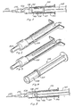
- Figure 1 is a side view and partially sectional view of a syringe in accordance with the invention,
- Figures 2 and 3 are perspective and partially sectional views of alternative embodiments of the cylinder of the syringe shown in Figure 1,
- Figure 4 is a perspective view of a piston or plunger for use in connection with the syringe cylinders shown in Figures 2 and 3, and
- Figure 5 is a side view and partially sectional view of a syringe as that shown in Figure 1 with another type of piston or plunger.
- The
syringe 100 shown in Figure 1 comprises asyringe cylinder 101, which is made from a suitable material such as glass or plastic, and which may be provided with a gas impervious barrier layer. Thesyringe 100 also comprises a piston orplunger 106 having apiston rod 105 and asealing ring 107. Thesyringe cylinder 101 is provided with ahollow neck 109, which has a frusto-conical outer peripheral surface. Ahollow needle 110 is mounted on asocket 111, which has an inner frusto-conical surface which is complementary to that of theneck 109, so that thesocket 111 may be mounted on theneck 109. All of these elements are well known in connection with syringes for use in collecting samples for blood gas analysis. Thepiston 106 and the inner end of thesyringe cylinder 101 define ablood collecting chamber 108 which is in communication with the bore of thehollow neck 109 and thehollow needle 110. - As best shown in Figures 2 and 3, one or more axially extending
recesses 102 are formed in the inner wall of thecylinder 101. Therecesses 102 extend from the open end of thesyringe cylinder 101 to a position axially spaced from the cylinder end, which is provided with thehollow neck 109. In Figure 2 the recess extends annularly along the total periphery of the syringe cylinder so as to form a cylinder section of an enlarged inner diameter. In the embodiment shown in Figure 3, a number of axially extending, narrow recesses are uniformly peripherally spaced. - The recess or
recesses 102 receive a gas pervious and liquid impervious material, such as a hydrofobic filter material, for example micro-porous polyethylene or polypropylene, or micro-porous polytetrafluoro-ethylene, for example of the type marketed under the trade name TEFLON. - When a blood sample is to be collected from an artery, the
piston 106 is positioned in such an axial position that the volume of theblood collecting chamber 108 substantially corresponds to the desired volume of the blood sample, and in that position thepiston sealing ring 107 must be in engagement with the gas pervious material arranged in therecesses 102. The pointed free end of thehollow needle 110 is now inserted into an artery so that arterial blood may flow through theneedle 110 and into thechamber 108 under the arterial blood pressure. Gas or air may then escape from theblood collecting chamber 108 through a venting passage formed by aspace 103 defined between the peripheral outer wall of thepiston 106 and the inner wall of thesyringe cylinder 101 and by the gas pervious material arranged within the recess orrecesses 102. When all of the air has been expelled from thechamber 108 and blood has penetrated into thespace 103 up to the sealingring 107, further progress of the blood is stopped, because gas, but not blood, can pass through the hydrofobic material in the recesses, and the hollow needle may now be removed from the artery. - As the hydrofobic material contains air or gas some contact between such gas and the blood within the
chamber 108 will exist. In order to reduce contamination of the collected blood sample by gas thepiston 106 has a relatively long axial length, and thesealing ring 107 is positioned at the outer end of the piston. This means that the blood within thechamber 108 is in contact with the gas containing hydrofobic material only through the relatively long,narrow space 103. - If necessary, these gas contamination problems may be further reduced by using a hydrophilic or swelling material in the
recesses 102. The relativelylong piston 106 shown in Figures 1 and 4 may be replaced by a short conventional piston as that shown in Figure 5. In that case subatmospheric pressure or suction may be provided by moving the piston from its innermost position adjacent to theneck 109 to a position adjacent to the inner end of therecesses 102. This may be of importance in cases where the arterial pressure is not sufficient to cause blood to flow into the ventedblood collecting chamber 108. - It should be understood that various changes and modifications of the embodiment shown above may be made within the scope of the present invention as defined in the claims. Thus the
recesses 102 may be shaped in any desired manner, and other kinds of pistons may be used in connection with the syringe.
Claims (8)
Priority Applications (1)
| Application Number | Priority Date | Filing Date | Title |
|---|---|---|---|
| AT83108434T ATE23793T1 (en) | 1982-08-27 | 1983-08-26 | SYRINGE FOR COLLECTING FLUID. |
Applications Claiming Priority (2)
| Application Number | Priority Date | Filing Date | Title |
|---|---|---|---|
| DK3855/82 | 1982-08-27 | ||
| DK385582 | 1982-08-27 |
Publications (3)
| Publication Number | Publication Date |
|---|---|
| EP0103224A2 EP0103224A2 (en) | 1984-03-21 |
| EP0103224A3 EP0103224A3 (en) | 1984-05-02 |
| EP0103224B1 true EP0103224B1 (en) | 1986-11-26 |
Family
ID=8127501
Family Applications (1)
| Application Number | Title | Priority Date | Filing Date |
|---|---|---|---|
| EP83108434A Expired EP0103224B1 (en) | 1982-08-27 | 1983-08-26 | A syringe for collecting a liquid sample |
Country Status (5)
| Country | Link |
|---|---|
| US (1) | US4519402A (en) |
| EP (1) | EP0103224B1 (en) |
| JP (1) | JPS5985668A (en) |
| AT (1) | ATE23793T1 (en) |
| DE (1) | DE3367844D1 (en) |
Cited By (1)
| Publication number | Priority date | Publication date | Assignee | Title |
|---|---|---|---|---|
| EP1406687A2 (en) * | 2001-07-13 | 2004-04-14 | Liebel-Flarsheim Company | Contrast delivery syringe with internal hydrophilic surface treatment for the prevention of bubble adhesion |
Families Citing this family (13)
| Publication number | Priority date | Publication date | Assignee | Title |
|---|---|---|---|---|
| JPS57190567A (en) * | 1981-05-20 | 1982-11-24 | Terumo Corp | Blood sampler with air removing and shielding mechanism |
| US4886072A (en) * | 1983-12-16 | 1989-12-12 | Becton, Dickinson And Company | Multiple sample needle assembly with vein indicator |
| DE3421955C2 (en) * | 1984-06-13 | 1986-10-09 | Walter Sarstedt Kunststoff-Spritzgußwerk, 5223 Nümbrecht | Sedimentation device |
| US4679571A (en) * | 1984-08-31 | 1987-07-14 | Becton, Dickinson And Company | Blood sample needle assembly with vein indicator |
| JPS6175208U (en) * | 1984-10-22 | 1986-05-21 | ||
| US4703763A (en) * | 1985-06-17 | 1987-11-03 | Sherwood Medical Company | Blood sample syringe |
| US4690153A (en) * | 1985-11-29 | 1987-09-01 | Becton, Dickinson And Company | Flow inducing means for small volume containers |
| JPH0747045B2 (en) * | 1986-10-15 | 1995-05-24 | 株式会社大協精工 | Stacked syringe stopper |
| CA2016734C (en) * | 1989-06-02 | 1994-03-22 | Thomas J. Dragosits | Syringe assembly |
| US5086780A (en) * | 1990-05-21 | 1992-02-11 | Abbott Laboratories | Blood collection device |
| US5314416A (en) * | 1992-06-22 | 1994-05-24 | Sherwood Medical Company | Low friction syring assembly |
| US7351228B2 (en) * | 2003-11-06 | 2008-04-01 | Becton, Dickinson And Company | Plunger rod for arterial blood collection syringes |
| US8012413B2 (en) * | 2006-12-21 | 2011-09-06 | Depuy Spine, Inc. | Gaseous sterilization of impermeable containers through use of porous material |
Family Cites Families (18)
| Publication number | Priority date | Publication date | Assignee | Title |
|---|---|---|---|---|
| US3943917A (en) * | 1972-11-06 | 1976-03-16 | Radiometer A/S | Method for collecting blood samples |
| US3978846A (en) * | 1975-01-02 | 1976-09-07 | Bailey Donald L | Syringe for taking blood samples |
| US3960139A (en) * | 1975-01-15 | 1976-06-01 | Bailey Donald L | Syringe device with means for removing contaminates when drawing blood sample |
| US4043336A (en) * | 1976-04-21 | 1977-08-23 | Kreb Iii Robert J | Sterile syringe device |
| US4133304A (en) * | 1977-04-29 | 1979-01-09 | Emde Corporation | Syringe-like apparatus with removable capillary cartridge |
| US4206768A (en) * | 1978-10-20 | 1980-06-10 | Marquest Medical Products, Inc. | Syringe device with means for selectively isolating a blood sample after removal of contaminates |
| US4266558A (en) * | 1979-04-02 | 1981-05-12 | American Hospital Supply Corporation | Method of collecting and dispensing a blood sample |
| US4266559A (en) * | 1979-04-02 | 1981-05-12 | American Hospital Supply Corporation | Blood sampler |
| US4257426A (en) * | 1979-06-22 | 1981-03-24 | Marquest Medical Products, Inc. | Vacuum assisted anti-coagulant syringe device for taking blood samples |
| US4326540A (en) * | 1979-11-06 | 1982-04-27 | Marquest Medical Products, Inc. | Syringe device with means for selectively isolating a blood sample after removal of contaminates |
| US4340067A (en) * | 1980-03-31 | 1982-07-20 | Rattenborg Christen C | Blood collection syringe |
| FI801834A (en) * | 1980-06-09 | 1981-12-10 | Jorma Lillbacka | ANORDNING FOER FASTPRESSNING AV KOPPLINGSSTYCKEN FOER SLANGAR |
| US4340068A (en) * | 1980-06-18 | 1982-07-20 | Becton, Dickinson And Company | Multiple sample needle with vein entry indicator |
| US4299238A (en) * | 1980-06-24 | 1981-11-10 | Baidwan Balinderjeet S | Vented piston and push-rod subassembly for use in a syringe barrel |
| US4327745A (en) * | 1980-09-02 | 1982-05-04 | The Deseret Company | Blood sampling device |
| US4448206A (en) * | 1981-08-17 | 1984-05-15 | Martell Michael D | Vented, aspirating syringe |
| US4373535A (en) * | 1981-08-17 | 1983-02-15 | Martell Michael D | Venting, self-stopping, aspirating syringe |
| JPS58138441A (en) * | 1982-02-15 | 1983-08-17 | テルモ株式会社 | Bloood sampler |
-
1983
- 1983-08-26 DE DE8383108434T patent/DE3367844D1/en not_active Expired
- 1983-08-26 EP EP83108434A patent/EP0103224B1/en not_active Expired
- 1983-08-26 AT AT83108434T patent/ATE23793T1/en not_active IP Right Cessation
- 1983-08-26 US US06/526,899 patent/US4519402A/en not_active Expired - Fee Related
- 1983-08-27 JP JP58157044A patent/JPS5985668A/en active Pending
Cited By (1)
| Publication number | Priority date | Publication date | Assignee | Title |
|---|---|---|---|---|
| EP1406687A2 (en) * | 2001-07-13 | 2004-04-14 | Liebel-Flarsheim Company | Contrast delivery syringe with internal hydrophilic surface treatment for the prevention of bubble adhesion |
Also Published As
| Publication number | Publication date |
|---|---|
| EP0103224A2 (en) | 1984-03-21 |
| US4519402A (en) | 1985-05-28 |
| JPS5985668A (en) | 1984-05-17 |
| ATE23793T1 (en) | 1986-12-15 |
| DE3367844D1 (en) | 1987-01-15 |
| EP0103224A3 (en) | 1984-05-02 |
Similar Documents
| Publication | Publication Date | Title |
|---|---|---|
| EP0103224B1 (en) | A syringe for collecting a liquid sample | |
| US4572210A (en) | Syringe with means for allowing passage of air while preventing the passage of blood to obtain a gas-free blood sample | |
| US4340067A (en) | Blood collection syringe | |
| US4999164A (en) | Pipetting device comprising a retaining cone for holding a slip-on pipette tip and pipette tip for such pipetting device | |
| US5833630A (en) | Sample collection device | |
| EP1529489B1 (en) | Plunger rod for arterial blood collection syringes | |
| US5520193A (en) | Blood collecting needle with vein indicator | |
| EP0180702B1 (en) | Blood sample needle assembly with vein indicator | |
| US5554127A (en) | Syringe needle thimble cap and method of use thereof | |
| US4660569A (en) | Venting, automatic-stopping, aspirating plungers for syringes | |
| FI67025B (en) | INJEKTIONSSPRUTA | |
| US20090012425A1 (en) | Apparatus and Method for Collecting a Sample of Material | |
| US7374723B2 (en) | System for collecting and releasing saliva | |
| US20030206828A1 (en) | Whole blood sampling device | |
| AU2801292A (en) | Assay device | |
| US20040022687A1 (en) | Device and process for collecting and releasing saliva | |
| EP0803064A1 (en) | Fluid sampling device | |
| NZ209258A (en) | Multiple sample needle assembly; chamber air passage contains aqueous absorbent material | |
| GB2050172A (en) | Syringes | |
| EP0117498A1 (en) | A liquid sampling device | |
| EP0102070A2 (en) | A liquid sampler | |
| GB2232599A (en) | One-step blood to plasma device | |
| EP2094337B1 (en) | Gaseous sterilization of impermeable containers through use of porous material | |
| DK147874B (en) | Syringe for taking a liquid sample | |
| EP0102073A2 (en) | A syringe for collecting a blood sample |
Legal Events
| Date | Code | Title | Description |
|---|---|---|---|
| PUAI | Public reference made under article 153(3) epc to a published international application that has entered the european phase |
Free format text: ORIGINAL CODE: 0009012 |
|
| PUAL | Search report despatched |
Free format text: ORIGINAL CODE: 0009013 |
|
| AK | Designated contracting states |
Designated state(s): AT BE CH DE FR GB IT LI LU NL SE |
|
| AK | Designated contracting states |
Designated state(s): AT BE CH DE FR GB IT LI LU NL SE |
|
| 17P | Request for examination filed |
Effective date: 19841029 |
|
| GRAA | (expected) grant |
Free format text: ORIGINAL CODE: 0009210 |
|
| AK | Designated contracting states |
Kind code of ref document: B1 Designated state(s): AT BE CH DE FR GB IT LI LU NL SE |
|
| PG25 | Lapsed in a contracting state [announced via postgrant information from national office to epo] |
Ref country code: NL Effective date: 19861126 Ref country code: LI Effective date: 19861126 Ref country code: IT Free format text: LAPSE BECAUSE OF FAILURE TO SUBMIT A TRANSLATION OF THE DESCRIPTION OR TO PAY THE FEE WITHIN THE PRESCRIBED TIME-LIMIT;WARNING: LAPSES OF ITALIAN PATENTS WITH EFFECTIVE DATE BEFORE 2007 MAY HAVE OCCURRED AT ANY TIME BEFORE 2007. THE CORRECT EFFECTIVE DATE MAY BE DIFFERENT FROM THE ONE RECORDED. Effective date: 19861126 Ref country code: FR Free format text: THE PATENT HAS BEEN ANNULLED BY A DECISION OF A NATIONAL AUTHORITY Effective date: 19861126 Ref country code: CH Effective date: 19861126 Ref country code: BE Effective date: 19861126 Ref country code: AT Effective date: 19861126 |
|
| REF | Corresponds to: |
Ref document number: 23793 Country of ref document: AT Date of ref document: 19861215 Kind code of ref document: T |
|
| PG25 | Lapsed in a contracting state [announced via postgrant information from national office to epo] |
Ref country code: SE Effective date: 19861130 |
|
| REF | Corresponds to: |
Ref document number: 3367844 Country of ref document: DE Date of ref document: 19870115 |
|
| REG | Reference to a national code |
Ref country code: CH Ref legal event code: PL |
|
| EN | Fr: translation not filed | ||
| NLV1 | Nl: lapsed or annulled due to failure to fulfill the requirements of art. 29p and 29m of the patents act | ||
| PG25 | Lapsed in a contracting state [announced via postgrant information from national office to epo] |
Ref country code: LU Free format text: LAPSE BECAUSE OF NON-PAYMENT OF DUE FEES Effective date: 19870831 |
|
| PLBE | No opposition filed within time limit |
Free format text: ORIGINAL CODE: 0009261 |
|
| STAA | Information on the status of an ep patent application or granted ep patent |
Free format text: STATUS: NO OPPOSITION FILED WITHIN TIME LIMIT |
|
| 26N | No opposition filed | ||
| PG25 | Lapsed in a contracting state [announced via postgrant information from national office to epo] |
Ref country code: GB Free format text: LAPSE BECAUSE OF NON-PAYMENT OF DUE FEES Effective date: 19880826 |
|
| PG25 | Lapsed in a contracting state [announced via postgrant information from national office to epo] |
Ref country code: DE Effective date: 19890503 |
|
| GBPC | Gb: european patent ceased through non-payment of renewal fee |