EP0103490A2 - Exercising apparatus - Google Patents
Exercising apparatus Download PDFInfo
- Publication number
- EP0103490A2 EP0103490A2 EP83305388A EP83305388A EP0103490A2 EP 0103490 A2 EP0103490 A2 EP 0103490A2 EP 83305388 A EP83305388 A EP 83305388A EP 83305388 A EP83305388 A EP 83305388A EP 0103490 A2 EP0103490 A2 EP 0103490A2
- Authority
- EP
- European Patent Office
- Prior art keywords
- leg
- stimulation
- muscle
- grasping
- load
- Prior art date
- Legal status (The legal status is an assumption and is not a legal conclusion. Google has not performed a legal analysis and makes no representation as to the accuracy of the status listed.)
- Withdrawn
Links
Images


Classifications
-
- A—HUMAN NECESSITIES
- A61—MEDICAL OR VETERINARY SCIENCE; HYGIENE
- A61N—ELECTROTHERAPY; MAGNETOTHERAPY; RADIATION THERAPY; ULTRASOUND THERAPY
- A61N1/00—Electrotherapy; Circuits therefor
- A61N1/18—Applying electric currents by contact electrodes
- A61N1/32—Applying electric currents by contact electrodes alternating or intermittent currents
- A61N1/36—Applying electric currents by contact electrodes alternating or intermittent currents for stimulation
- A61N1/36003—Applying electric currents by contact electrodes alternating or intermittent currents for stimulation of motor muscles, e.g. for walking assistance
-
- Y—GENERAL TAGGING OF NEW TECHNOLOGICAL DEVELOPMENTS; GENERAL TAGGING OF CROSS-SECTIONAL TECHNOLOGIES SPANNING OVER SEVERAL SECTIONS OF THE IPC; TECHNICAL SUBJECTS COVERED BY FORMER USPC CROSS-REFERENCE ART COLLECTIONS [XRACs] AND DIGESTS
- Y10—TECHNICAL SUBJECTS COVERED BY FORMER USPC
- Y10S—TECHNICAL SUBJECTS COVERED BY FORMER USPC CROSS-REFERENCE ART COLLECTIONS [XRACs] AND DIGESTS
- Y10S482/00—Exercise devices
- Y10S482/901—Exercise devices having computer circuitry
Definitions
- the invention which is disclosed and claimed herein has particular value in the treatment of persons who have suffered injuries resulting in spinal cord damage. This particular type of damage often times produces partial or total paralysis of muscles which are controlled from a point below the point of spinal cord damage. The victim then faces a life of relative inactivity and deterioration of muscles which otherwise would be active. It has now been found in accordance with this invention that such muscles can be stimulated to engage in an exercise program once thought to be impossible. Moreover, it has been found that such an exercise program can restore normal muscle tone, even after years of inactivity.
- Maurer U.S. Patent No. 3,817,254 (1974), discloses a transcutaneous stimulator for use-in suppressing pain designed to differentially stimulate touch versus pain nerve fibers in an effort to reduce the prickly sensation known to accompany some pain therapy.
- Maurer notes that differences in the response of nerves to electro-stimulation can be used to selectively stimulate different types of nerves.
- nerve fibers are distinguished in terms of their size and conduction velocity. He notes that the amplitude of electrical stimulation required to elicit a muscle response increases as the fiber size decreases.
- the Petrofsky article teaches that electrostimulation can be controlled by a microprocessor in such a way as to develop isometric contractions in a muscle. However, there is no teaching of any method or apparatus for causing smooth, natural isokinetic contractions. Also, the techniques taught by Petrofsky are not applied to man.
- a stimulation device which generates a pair of stimulation signals comprising alternately generated pulses of stimulation energy.
- the stimulation signals are applied across pairs of electrodes which are preferably adhered to the skin immediately above a muscle to be stimulated.
- a plurality of transcutaneous stimulators are applied to the skin of the subject in a pattern for stimulating a muscle which is connected for moving the limb to be exercised.
- the stimulators are then excited by a plurality of stimulation signals having profiles for causing the muscle to contract and produce a predetermined movement of the limb.
- a resisting force is applied thereagainst to cause exertion of the muscle during its contraction.
- the movement of the limb is sensed and a corresponding feedback signal is generated.
- the feedback signal is monitored to determine when a predetermined movement has been achieved.
- the stimulation signals are altered to permit the limb to return to its initial position. The process is then repeated to produce an exercise routine.
- Leg strap 19 has a steel eyelet for fastening to one or the other of a pair of scissor-type eyelet fasteners 21, 22. Fasteners 21 and 22 are attached to pair .of cables 33, 34, ' respectively, which extend through a facing board 24.
- _Toothed belt 35 extends around a pair of toothed rollers 37 and 38 mounted between a pair of support plates 41a and 41b, as best illustrated in Fig. 4.
- Support plates 41a and 41b are securely supported by frame member 40, which in turn is supported by frame member 39.
- Belt 35 supports a set of weights placed upon a pan 42. Thus when the leg 31 moves arcuately as indicated by arrow 46, the weights 27 are raised or lowered.
- the arrangement provides a dynamic load which resists but does not prevent movement of leg 31.
- potentiometer 17 When the leg 31 is extended upwardly, pulling cable 33 and belt 35, the movement is measured by a potentiometer 17 (see Fig. 4) attached to roller 38 by a coupling device 44.
- the housing for potentiometer 17 is supported by a support arm 43 secured to the upper support plate 41, as viewed in Fig. 4.
- the potentiometer 17 transmits a feedback signal to A/D converter 12.
- A/D converter 12 converts the feedback signal into a digital format for processing by computer 13, as hereinafter described in detail.
- Computer 13 responds to the feedback signal by transmitting a digital control signal to D/A converter 14.
- D/A converter 14 then generates an analog stimulation signal for stimulator 50.
- Stimulator 50 uses the control signal from D/A converter 14 for generation of a pair of stimulation signals which are applied across electrodes 15a, 15b and 15c.
- Electrodes 15a, 15b and 15c are commercially available transcutaneous electrodes such as MEDTRONIC Model 3793 electrodes sold by Medtronic, Inc. of Minneapolis, Minnesota.
- the electrodes are placed in spaced positions above the quadriceps muscles of one leg, as generally illustrated in Fig. 2.
- the electrodes are attached to the leg of the subject by hypoallergenic tape or elastic bandages.
- An electrode gel such as TENS electrode gel, also sold by Medtronic, Inc. is applied to the electrodes before they are placed upon the skin of the subject.
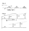
- Stimulator 50 generates a first signal 301 as illustrated by the top line of Fig. 8 and a second signal 302 as illustrated by the bottom line of Fig. 8.
- Signal 301 is applied across terminals 15a and 15c, while signal 302 is applied terminals 15b and 15c.
- Terminal 15c is connected to high voltage ground, as hereinafter described with reference to Fig. 5.
- Each of signals 301 and 302 has an envelope generally illustrated by triangular projections 303 rising above the line 300 of Fig. 7.
- the signal is characterized by alternating stimulation and rest periods of approximately 6 seconds each.
- the signal is pulsed at a frequency in a range from about 55 to 65 Hz and preferably about 60 Hz.
- the pulses which are so generated have peak values which increase gradually from a value near 0 volts to a maximum which is somewhat less than 255 volts and which produces maximum effort from the muscle or muscle group being stimulated. Thereafter the pulse amplitudes decrease gradually to a value near zero, and the muscle is rested.
- the maximum voltage value depends upon the state of exhaustion of the muscle and the effort which is desired. As the muscle tires, more stimulation voltage is required for production of the same effort. Generally speaking a maximum voltage of about 255 volts produces recruitment of all motor units and results in maximum effort by the muscle.
- signal 301 comprises a series of pulses 304 while signal 302 comprises another series of pulses 305.
- Pulses 304 and 305 are generated in an alternating sequence at a frequency of 60Hz each. Thus the effective combined frequency is 120Hz.
- Pulses 304 and 305 have peak values which conform with the signal enevelope of Fig. 7. They have a duration of approximately 500 microseconds, so that each of signals 301 and 302 has a duty cycle of 0.03. It has been found that if the pulse width is increased, then the stimulation voltage may be decreased and vice versa.
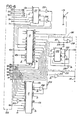
- circuitry for producing signals 301 and 302 is illustrated in Fig. 5.
- the associated feedback and control circuitry is illustrated schematically in Fig. 6.
- the circuitry includes integrated circuits as identified in Table I and components as identified in Table II. Table III lists significant pin number designations for the principal integrated circuits listed in Table I.
- IC 101 is connected to operate as a 60 Hz free running multivibrator.
- the output from IC 101 is. applied via transistor 104 to input pins 2 of IC 102 and 103.
- IC 102 and 103 produce alternating 500 microsecond pulses each at a frequency of 60 Hz for application to the collector terminals of transistors 105 and 106.
- the pulse width is set by appropriate selection of the resistance for resistors R116 and R124 and the capacitance of capacitors 117 and 125, as shown in the manufacturer's data sheets for integrated circuits 102 and 103.
- the phase between the pulses produced by integrated circuits 102 and 103 is set by appropriate selection of the resistance for resistors 113 and 114.
- Output voltage pulses from transformers 110 and 109 are applied to the base terminals of transistors 112 and 111 respectively.
- Transistors 112 and 111 provide a current gain so as to have high current, high voltage and low duty cycle pulses available for application across terminal pairs 15a-15c and 15b-15c.
- the analog driving signal appearing at line 197 is generated by the control system circuitry as illustrated in Fig. 6.
- the heart of the control system is the computer 13, which in the embodiment described herein is an APPLE II computer sold by Apple Computer Inc. of Cupertino, ' California.
- the APPLE II computer is provided with several slots into which may be plugged connectors for customized peripheral devices.
- the system described herein is plugged into slot number 3, which includes a connector 200 as illustrated by dotted lines in Fig. 6.
- the computer addresses analog .to digital converter 12 and digital to analog computer 13 through a decoder/demultiplexer 201.
- the peripheral board is addressed by the computer in memory locations C100 to C1FF (hexadecimal notation). Pin number 1 of connector 200 provides a signal from the computer's input/output select line.
- Pin number 1 is tied to pin number 5 of IC 201, an SN74LS138 integrated circuit.
- Pin number 5 is the G2 input of IC 201.
- a signal at this terminal enables IC 201 to decode the three high order bits (A7, A6, and A5) of an eight-bit address provided by the computer. These three bits appear at pin numbers 9, 8 and 7 respectively of connector 200.
- IC 201 is designed for producing eight decoded outputs, but only three of these outputs are used. These outputs appear at pin numbers 14, 12 and 10 and respectively read A/D converter 12, strobe D/A converter 14 and strobe A/D converter 12.
- A/D converter 12 is an eight channel device sold by National Semiconductor under the designation ADC0808. A/D converter 12 receives its clock from the system clock on pin number 40 of connector 200.
- A/D converter 12 When a strobe signal appears at pin number 12 of IC 201, A/D converter 12 is enabled for reading and digitizing analog signals appearing at any one of eight analog input ports (only two of which are used). The two analog input ports are addressed by a three-bit address appearing at pin numbers 25, 24 and 23 of A/D converter 12. The three address bits are the three least significant bits of an eight-bit address generated by computer 13. These three bits appear at pin numbers 2, 3 and 4 of'connector 200 (the three most significant bits appearing at pin numbers 7, 8 and 9 as above stated and bit numbers 3 and 4 not being utilized.
- Computer 13 generates the above mentioned eight-bit address whenever any one of computer memory address locations 50080 to 50087 (decimal notation) are strobed. Such strobing not only generates an associated eight-bit address, but also enables A/D converter 12 by causing generation of a strobe signal at output pin 12 of IC201, as above described.
- Memory locations 50080 to 50087 are strobed by execution of a "POKE" instruction, such as, for instance, the instruction "POKE 50080,0" appearing at line number 1450 of the computer program set forth in TABLE IV hereof.
- the described embodiment supplies only two analog input signals for digitizing by. A/D converter 12. These two signals appear at pin numbers 3 and 28 of A/D converter 12 and are addressed respectively by "POKING" memory locations 50080 and 50082 respectively. The resulting digitized representation thereof appears in eight-bit format at pin numbers 17, 14, 15, 8, 18, 19, 20 and 21 of A/D converter 12. These eight bits are read into memory location 49952 (decimal notation) upon execution of a "PEEK" instruction.
- A/D converter 12 is strobed to start conversion of the analog signal to digital format.
- a maximum of 100 microseconds is required for the analog to digital conversion, after which the computer may execute a normal memory read, cycle, whereby the digitized data is transferred onto the data bus and stored in memory location 49952.
- the output of A/D converter 12 is a eight-bit binary signal ranging between values of 0 and 255 (decimal) for analog input voltages between 0 and 5 volts.
- the analog signal supplied to pin No. 3 of A/D converter 12 has a triangular voltage profile and is produced by a profile generating circuit 202, comprising IC 204, amplifier 209, capacitors 219 and 220, and resistors 219 through 223.
- IC 204 generates a square wave at 1/6 Hz which is converted to a triangular ramp by capacitor 219 and resistor 221 and is buffered by amplifier 209.
- the triangular voltage profile,. so generated, represents a desired response from potentiometer 17 when the leg of the subject is being stimulated to raise and lower.
- potentiometer 17 is applied to pin No. 28 of A/D converter i2, as shown in Fig. 6.
- An output of 5 volts from potentiometer 17 represents a shaft angle rotation of 360°.
- the diameter of roller 38 is selected such that one rotation thereof corresponds to a leg movement of about 70 degrees from its initial vertial position.
- the amplitude of the analog stimulation signal appearing at line 197 is controlled by D/A converter 14, a DAC0831 integrated circuit sold by National Semiconductor. D/A converter 14 is selected for operation by applying a strobe signal to pin 19 thereof. Also, a write signal (logic LO) is applied to input terminals 1 and 2 for activating the transfer of data to the internal latch register of D/A converter 14. The data so transferred is an eight-bit stimulation command code appearing at terminals 13, 14, 15, 16, 4, 5, 6 and 7 of D/A converter 13. The output of D/A converter 14 is buffered and amplified and thereafter applied to input line 197 of stimulator 50.
- Computer 13 generates eight-bit binary representation of stimulation command voltages ranging between 0 and 255 by executing an appropriate POKE instruction.
- a desired stimulation voltage ranging between 0 and 255 is POKED into memory location 50016 (decimal).
- the computer When this memory location is POKED the computer generates an address for IC201 which causes output pin 12 to go LO.
- This LO output signal is inverted by inverter 205 to create the above mentioned strobe signal for D/A converter 14.
- the program set forth in TABLE IV includes an isometric strength measurement routine beginning at line 220 and a main control program beginning at line 1000.
- the main control program includes a start cycle beginning at line 1250 and a muscle stimulation routine beginning at line 1432.
- the start cycle finds the beginning of a ramp generated by the profile generator 202.
- the computer increments a variable Y from 1 to 17 (line 290) and POKES the value 10Y into memory location 50016. This causes generation of stimulation pulses having a voltage equal to the value 10Y.
- thetest supervisor depresses the Escape key on the computer control board. This action loads the ASCII code 155 into memory location 49152.
- the computer checks that memory location at line 329 and jumps to line 400 if the Escape key has been depressed. The computer then assigns the current value of 10Y to the variable Z as a threshold voltage.
- the computer enters the main control program to determine the maximum strength of the muscle by isokinetic exercise. During this routine the computer steps the stimulation voltage from the value Z up to 255 volts in 10 volt steps (lines 1045 and 1060). During this period of time the leg is attached to cable 34 as indicated by Fig. 3. When strength meter 36 indicates that the strength has leveled off, then the test supervisor again depresses the Escape key. The computer checks memory location 49152 once during each voltage step (line 1105) and proceeds to line 1120, if the Escape key has been depressed.
- the isokinetic exercise routine begins at line 1432. During this routine the computer generates stepped variations for a variable Z9 and POKES the value of Z9 into memory location 50016. After each new value of Z9 has been utilized for generation of a corresponding stimulation voltage, the computer checks to see if Z9 has a value equal to 255 (maximum stimulation voltage). If that value is noted, than the isokinetic exercise routine is terminated. If not, the computer proceeds to execute the instructions at line 1450 which cause reading of the analog voltages generated by profile generator 202 and potentiometer 17. These voltages are digitized and utilized to establish values for variables A8 and A9 respectively.
- A8 is greater than A9, the computer knows that the leg is not raised as much as it should be, and the value of Z9 is increased. This then increases the stimulation voltage command generated by the computer. Conversely, if A8 is less than A9, Z9 and the stimulation command are decreased. When A8 has decreased to a value indicating the end of a cycle, then the leg is rested for the duration of a counting loop which continues for approximately 6 seconds.
- a complete exercise procedure is therefore seen to include the following steps:
Abstract
Description
- The present invention rebates to
apparatus for exercising and, more particularly, to computer controlled . apparatus for monitoring muscular activity and adjusting an electrical stimulus to provide controlled and sustained isokinetic contractions. Still more particularly the present invention
relates to apparatus for directing coordinated movement of several muscles and exercising them through a specific exercise routine having therapeutic applications in the treatment of paralysis. - The invention which is disclosed and claimed herein has particular value in the treatment of persons who have suffered injuries resulting in spinal cord damage. This particular type of damage often times produces partial or total paralysis of muscles which are controlled from a point below the point of spinal cord damage. The victim then faces a life of relative inactivity and deterioration of muscles which otherwise would be active. It has now been found in accordance with this invention that such muscles can be stimulated to engage in an exercise program once thought to be impossible. Moreover, it has been found that such an exercise program can restore normal muscle tone, even after years of inactivity.
- Since the work of Galvani in 1791, it has been known that electricity can be used to induce muscle contractions. Recently, there has been increased awareness of the value of electrostimulation in muscle therapy.
- -Numerous devices and techniques have been developed for supplying electrical pulses as part of a therapeutic regime of muscle stimulation. Several examples of these are found in the patent literature. Radwan, U.S. Patent No. 3,387,147 (1968) discloses a muscle stimulating pulse generator designed to provide a pulse signal having a relatively high voltge-to-width ratio and a steep rising wavefront.
- Maurer, U.S. Patent No. 3,817,254 (1974), discloses a transcutaneous stimulator for use-in suppressing pain designed to differentially stimulate touch versus pain nerve fibers in an effort to reduce the prickly sensation known to accompany some pain therapy. Maurer notes that differences in the response of nerves to electro-stimulation can be used to selectively stimulate different types of nerves. According to Maurer, nerve fibers are distinguished in terms of their size and conduction velocity. He notes that the amplitude of electrical stimulation required to elicit a muscle response increases as the fiber size decreases.
- Nawracaj et al, U.S. Patent No. 4,071,033 (1978), discloses an electrostimulation device which utilizes a heterodyne effect to produce an otherwise painful low frequency stimulus in a muscle and cause the muscle to contract and relax at a low frequency.
- Wyss et al, U.S. Patent No. 4,148,321 (1979), discloses a muscular therapy similar in some respects to Nawracaj et al wherein muscles are made to rhythmically contract and relax at a very low frequency which is induced by modulating a medium frequency current between 3,000 and 100,000 Hz with a low frequency current less than 1 Hz. In one embodiment Wyss et al uses a phase shifter to transform the modulated output current into a three phase current, which is delivered to three electrodes angularly spaced about a limb to provide deep uniform stimulation.
- Kofskey et al, U.S. Patent No. 4,177,819 (1979), teaches an apparatus for stimulating a muscle for 2 to 20 seconds at 2 to 50 second intervals using a 2000 to 3000 Hz signal modulated at 40 to 50 Hz. In one embodiment, the muscle stimulating waveform is controlled by a microprocessor which gradually increases and decreases the amplitude of the stimulation at the beginning and end of each pulse. The microprocessor responds to signals from a no-load/overload sensor and to a manually controlled gain setting signal.
- It can be seen that the efforts embodied in the foregoing patents focus on the stimulus itself as the therapeutic agent and have as a principal objective to optimize the intensity, duration and frequency of the stimulus to enhance its therapeutic effects. In the disclosed therapies, the muscle is not stimulated against a load. These prior art systems do not provide smooth isometric contractions and do not respond to muscle activity response to muscle activity in these prior systems.
- In order to train a muscle and make it physically strong, it is necessary to work the muscle against a load while producing powerful, sustained, isokinetic contractions at a substantial proportion of the muscle's strength. Isokinetic contractions cannot be maintained for prolonged periods of time in the aforementioned therapies, because they stimulate the muscle synchronously using frequencies much higher than normal physiological frequencies. This causes the muscle to fatigue rapidly, making it impossible to maintain muscle tension.
- Petrofsky, "Microprocessor Controlled Stimulation in Paralyzed Muscle", IEEE August 1979 outlines a computer-controlled stimulation system which mimics normal asynchronous recruitment of motor units and firing rate control in the gastrocnemius muscle of a cat. A computer was programmed to set the recruitment order pf the motor units as it sensed fatigue in the muscle. This was accomplished by using an anodal block electrode in combination with a sequential electrode sleeve. The electrode sleeve was placed around the motor nerve to the muscle and was configured for alternately stimulating three groups of neurons in the nerve. The anodal block electrode was placed just proximal to the muscle. Muscle fatigue was sensed by a strain gauge transducer mounted on a bar attached to one end of the muscle.
- The Petrofsky article teaches that electrostimulation can be controlled by a microprocessor in such a way as to develop isometric contractions in a muscle. However, there is no teaching of any method or apparatus for causing smooth, natural isokinetic contractions. Also, the techniques taught by Petrofsky are not applied to man.
- It is an object of the present invention to provide a method and apparatus for electrically stimulating a muscle and exercising the muscle through a specific exercise routine based upon feedback control.
- JEt is another object of this invention to provide apparatus and method for stimulating a human muscle to contract against a dynamic load.
- It is still another object of the invention to provide improved apparatus and method for stimulating contraction of a human muscle.
- These and other objects of the present invention are accomplished through use of a stimulation device which generates a pair of stimulation signals comprising alternately generated pulses of stimulation energy. The stimulation signals are applied across pairs of electrodes which are preferably adhered to the skin immediately above a muscle to be stimulated.
- In the preferred embodiment the stimulation apparatus is controlled through a digital to analog converter by a digitally controlled microprocessor. The limb which is moved by the stimulated muscle is secured against a dynamic load which yieldingly resists movement of the muscle. A feedback sensor senses the movement actually achieved by the limb and transmits an indication thereof through an analog to digital converter back to the microprocessor.
- In an exercise routine according to the present invention, a plurality of transcutaneous stimulators are applied to the skin of the subject in a pattern for stimulating a muscle which is connected for moving the limb to be exercised. The stimulators are then excited by a plurality of stimulation signals having profiles for causing the muscle to contract and produce a predetermined movement of the limb. While the limb is contracting, a resisting force is applied thereagainst to cause exertion of the muscle during its contraction. The movement of the limb is sensed and a corresponding feedback signal is generated. The feedback signal is monitored to determine when a predetermined movement has been achieved. After the predetermined movement has been achieved, the stimulation signals are altered to permit the limb to return to its initial position. The process is then repeated to produce an exercise routine.
- In order that the invention may be more readily understood, reference will now be made to the. accompanying drawings, in which:
- Fig. 1 is a schematic illustration of exercising apparatus in accordance with the present invention;
- Fig. 2 is a side elevation view of an exercise chair;
- Fig. 3 is an illustration of means for indicating the isometric load developed by a human leg;
- Fig. 4 is a view taken along
line 4--4 of Fig. 2; - Fig. 5 is a schematic illustration of a stimulation apparatus;
- Fig. 6 is a schematic illustration of a control system for the stimulation apparatus of Fig. 5;'
- Fig. 7 is a schematic illustration of a stimulation signal; and
- Fig. 8 is an enlarged schematic illustration of portions of two alternately pulsed stimulation signals.
- Fig. 1 illustrates an
exercise system 10 constructed in accordance with this invention. The exercise system may comprise achair 16 mounted on asupport frame 11.Chair 16 rests upon asupport board 30 and is clamped in place by aclamp plate 28, as illustrated in Fig. 2.Clamp plate 28 may be forced upwardly against the lower surface ofsupport board 30 by any convenient means, such as, for instance, a rotary handle and screwarrangement 29. Whenclamp 28 is releasedchair 16 may be moved along the surface ofsupport board 30 as illustrated by thearrow 45. This enables positioning ofchair 16 for accommodating an exercise routine for either the left leg or the right leg of a person seated inchair 16. -
Exercise system 10 also comprises aseat belt 18 for securing a person inchair 16 and aleg strap 19 for grasping the lower portion of aleg 31.Leg strap 19 is provided with interlocking pieces of hook andloop fastening fabric leg strap 19 be easily and securely fastened around a leg of any size. -
Leg strap 19 has a steel eyelet for fastening to one or the other of a pair of scissor-type eyelet fasteners Fasteners cables board 24. -
Cables roller 23 having a pair of offset guide channels (not illustrated).Cable 33 extends rearwardly fromroller 23 around aroller 36 and thence upwardly for attachment to a toothed belt 35.Cable 34 wraps aroundroller 23 and extends upwardly for attachment to a relativelystiff bending arm 25 supported uponframe member 39, as best illustrated in Fig. 3. - _Toothed belt 35 extends around a pair of
toothed rollers frame member 40, which in turn is supported byframe member 39. - Belt 35 supports a set of weights placed upon a
pan 42. Thus when theleg 31 moves arcuately as indicated byarrow 46, theweights 27 are raised or lowered. The arrangement provides a dynamic load which resists but does not prevent movement ofleg 31. - When the
leg 31 is extended upwardly, pullingcable 33 and belt 35, the movement is measured by a potentiometer 17 (see Fig. 4) attached toroller 38 by acoupling device 44. The housing forpotentiometer 17 is supported by a support arm 43 secured to the upper support plate 41, as viewed in Fig. 4. - As the
leg 31 moves and pulls belt 35 acrossroller 38, thepotentiometer 17 transmits a feedback signal to A/D converter 12. A/D converter 12 converts the feedback signal into a digital format for processing bycomputer 13, as hereinafter described in detail.Computer 13 responds to the feedback signal by transmitting a digital control signal to D/A converter 14. D/A converter 14 then generates an analog stimulation signal forstimulator 50.Stimulator 50 uses the control signal from D/A converter 14 for generation of a pair of stimulation signals which are applied acrosselectrodes Electrodes - For an exercise as hereinafter described the electrodes are placed in spaced positions above the quadriceps muscles of one leg, as generally illustrated in Fig. 2. The electrodes are attached to the leg of the subject by hypoallergenic tape or elastic bandages. Prior to application of the electrodes, the skin is cleaned and dried. An electrode gel, such as TENS electrode gel, also sold by Medtronic, Inc. is applied to the electrodes before they are placed upon the skin of the subject.
- When the stimulation signals from
stimulator 50 are applied toelectrodes leg 31 against the dynamic resistance ofcable 33 as described above. Alternatively,leg strap 19 may be connected tocable 34 in whichcase leg 31 strains isometrically against bendingarm 25. This produces an output signal from astrain gauge 32 mounted on top of bendingarm 25.Strain gauge 32 is connected to provide a load signal for ameter 26 which may be mounted at any convenient location. Themeter 26 provides a "strength" indication for use in the exercise procedure hereinafter described in detail. - The stimulation signals which are applied to
electrodes Stimulator 50 generates afirst signal 301 as illustrated by the top line of Fig. 8 and a second signal 302 as illustrated by the bottom line of Fig. 8.Signal 301 is applied acrossterminals terminals - Each of
signals 301 and 302 has an envelope generally illustrated bytriangular projections 303 rising above theline 300 of Fig. 7. The signal is characterized by alternating stimulation and rest periods of approximately 6 seconds each. During the stimulation period the signal is pulsed at a frequency in a range from about 55 to 65 Hz and preferably about 60 Hz. The pulses which are so generated have peak values which increase gradually from a value near 0 volts to a maximum which is somewhat less than 255 volts and which produces maximum effort from the muscle or muscle group being stimulated. Thereafter the pulse amplitudes decrease gradually to a value near zero, and the muscle is rested. The maximum voltage value depends upon the state of exhaustion of the muscle and the effort which is desired. As the muscle tires, more stimulation voltage is required for production of the same effort. Generally speaking a maximum voltage of about 255 volts produces recruitment of all motor units and results in maximum effort by the muscle. - As shown in Fig. 8, signal 301 comprises a series of
pulses 304 while signal 302 comprises another series ofpulses 305.Pulses Pulses signals 301 and 302 has a duty cycle of 0.03. It has been found that if the pulse width is increased, then the stimulation voltage may be decreased and vice versa. - -The circuitry for producing
signals 301 and 302 is illustrated in Fig. 5. The associated feedback and control circuitry is illustrated schematically in Fig. 6. The circuitry includes integrated circuits as identified in Table I and components as identified in Table II. Table III lists significant pin number designations for the principal integrated circuits listed in Table I.


- The operation of
stimulator 50 will now be described with reference to Fig. 5. That figure shows 3integrated circuits IC 101 is connected to operate as a 60 Hz free running multivibrator. The output fromIC 101 is. applied viatransistor 104 to inputpins 2 ofIC IC transistors capacitors integrated circuits integrated circuits resistors 113 and 114. - An analog voltage representing the desired envelope for the stimulation pulses is applied to input
line 197, which is connected to the base terminals oftransistors pin 3 ofIC 102 andpin 3 ofIC 103 are applied to the collectors oftransistors result thereof transistors resistors transistors transformers - The voltage pulses across the primary windings of
transformers transformers transformers - Output voltage pulses from
transformers transistors 112 and 111 respectively.Transistors 112 and 111 provide a current gain so as to have high current, high voltage and low duty cycle pulses available for application acrossterminal pairs 15a-15c and 15b-15c. The analog driving signal appearing atline 197 is generated by the control system circuitry as illustrated in Fig. 6. - The heart of the control system is the
computer 13, which in the embodiment described herein is an APPLE II computer sold by Apple Computer Inc. of Cupertino, ' California. The APPLE II computer is provided with several slots into which may be plugged connectors for customized peripheral devices. The system described herein is plugged intoslot number 3, which includes a connector 200 as illustrated by dotted lines in Fig. 6. The computer addresses analog .todigital converter 12 and digital toanalog computer 13 through a decoder/demultiplexer 201. The peripheral board is addressed by the computer in memory locations C100 to C1FF (hexadecimal notation).Pin number 1 of connector 200 provides a signal from the computer's input/output select line. This line becomes active whenever one of the memory locations ClFF to C100 are selected for memory read or write operations.Pin number 1 is tied to pinnumber 5 ofIC 201, an SN74LS138 integrated circuit.Pin number 5 is the G2 input ofIC 201. A signal at this terminal enablesIC 201 to decode the three high order bits (A7, A6, and A5) of an eight-bit address provided by the computer. These three bits appear atpin numbers -
IC 201 is designed for producing eight decoded outputs, but only three of these outputs are used. These outputs appear atpin numbers D converter 12, strobe D/A converter 14 and strobe A/D converter 12. A/D converter 12 is an eight channel device sold by National Semiconductor under the designation ADC0808. A/D converter 12 receives its clock from the system clock onpin number 40 of connector 200. - When a strobe signal appears at
pin number 12 ofIC 201, A/D converter 12 is enabled for reading and digitizing analog signals appearing at any one of eight analog input ports (only two of which are used). The two analog input ports are addressed by a three-bit address appearing atpin numbers D converter 12. The three address bits are the three least significant bits of an eight-bit address generated bycomputer 13. These three bits appear atpin numbers pin numbers bit numbers -
Computer 13 generates the above mentioned eight-bit address whenever any one of computer memory address locations 50080 to 50087 (decimal notation) are strobed. Such strobing not only generates an associated eight-bit address, but also enables A/D converter 12 by causing generation of a strobe signal atoutput pin 12 of IC201, as above described. Memory locations 50080 to 50087 are strobed by execution of a "POKE" instruction, such as, for instance, the instruction "POKE 50080,0" appearing at line number 1450 of the computer program set forth in TABLE IV hereof. - As mentioned above, the described embodiment supplies only two analog input signals for digitizing by. A/
D converter 12. These two signals appear atpin numbers D converter 12 and are addressed respectively by "POKING" memory locations 50080 and 50082 respectively. The resulting digitized representation thereof appears in eight-bit format atpin numbers D converter 12. These eight bits are read into memory location 49952 (decimal notation) upon execution of a "PEEK" instruction. - It is therefore seen that when memory addresses 50080 through 50087 are strobed, the conputer selects the analog channel which is to be multiplexed into A/
D converter 12. Simultaneously with this selection A/D converter 12 is strobed to start conversion of the analog signal to digital format. A maximum of 100 microseconds is required for the analog to digital conversion, after which the computer may execute a normal memory read, cycle, whereby the digitized data is transferred onto the data bus and stored in memory location 49952. It is to be noted that the output of A/D converter 12 is a eight-bit binary signal ranging between values of 0 and 255 (decimal) for analog input voltages between 0 and 5 volts. - The analog signal supplied to pin No. 3 of A/
D converter 12 has a triangular voltage profile and is produced by aprofile generating circuit 202, comprisingIC 204,amplifier 209,capacitors resistors 219 through 223.IC 204 generates a square wave at 1/6 Hz which is converted to a triangular ramp bycapacitor 219 and resistor 221 and is buffered byamplifier 209. The triangular voltage profile,. so generated, represents a desired response frompotentiometer 17 when the leg of the subject is being stimulated to raise and lower. - The output of
potentiometer 17 is applied to pin No. 28 of A/D converter i2, as shown in Fig. 6. An output of 5 volts frompotentiometer 17 represents a shaft angle rotation of 360°. The diameter ofroller 38 is selected such that one rotation thereof corresponds to a leg movement of about 70 degrees from its initial vertial position. - The amplitude of the analog stimulation signal appearing at
line 197 is controlled by D/A converter 14, a DAC0831 integrated circuit sold by National Semiconductor. D/A converter 14 is selected for operation by applying a strobe signal to pin 19 thereof. Also, a write signal (logic LO) is applied to inputterminals A converter 14. The data so transferred is an eight-bit stimulation command code appearing atterminals A converter 13. The output of D/A converter 14 is buffered and amplified and thereafter applied to inputline 197 ofstimulator 50. -
Computer 13 generates eight-bit binary representation of stimulation command voltages ranging between 0 and 255 by executing an appropriate POKE instruction. A desired stimulation voltage ranging between 0 and 255 is POKED into memory location 50016 (decimal). When this memory location is POKED the computer generates an address for IC201 which causesoutput pin 12 to go LO. This LO output signal is inverted byinverter 205 to create the above mentioned strobe signal for D/A converter 14. - The computer program for producing the above described operation is described in the program listing set forth in TABLE IV. This program is written in source code in accordance with the APPLESOFT variation of the well known BASIC language. The program will be self-explanatory to persons skilled in the art and only brief comments need be made.
- The program set forth in TABLE IV includes an isometric strength measurement routine beginning at
line 220 and a main control program beginning at line 1000. The main control program includes a start cycle beginning at line 1250 and a muscle stimulation routine beginning at line 1432. The start cycle finds the beginning of a ramp generated by theprofile generator 202. - During the isometric measurement routine the computer increments a variable Y from 1 to 17 (line 290) and POKES the value 10Y into memory location 50016. This causes generation of stimulation pulses having a voltage equal to the value 10Y. When the muscle begins to develop tension, then thetest supervisor depresses the Escape key on the computer control board. This action loads the ASCII code 155 into memory location 49152. The computer checks that memory location at line 329 and jumps to
line 400 if the Escape key has been depressed. The computer then assigns the current value of 10Y to the variable Z as a threshold voltage. - After the threshold voltage has been established, the computer enters the main control program to determine the maximum strength of the muscle by isokinetic exercise. During this routine the computer steps the stimulation voltage from the value Z up to 255 volts in 10 volt steps (lines 1045 and 1060). During this period of time the leg is attached to
cable 34 as indicated by Fig. 3. Whenstrength meter 36 indicates that the strength has leveled off, then the test supervisor again depresses the Escape key. The computer checks memory location 49152 once during each voltage step (line 1105) and proceeds to line 1120, if the Escape key has been depressed. - After the maximum strength has been determined, the computer looks for a start of a cycle (line 1250).
- The isokinetic exercise routine begins at line 1432. During this routine the computer generates stepped variations for a variable Z9 and POKES the value of Z9 into memory location 50016. After each new value of Z9 has been utilized for generation of a corresponding stimulation voltage, the computer checks to see if Z9 has a value equal to 255 (maximum stimulation voltage). If that value is noted, than the isokinetic exercise routine is terminated. If not, the computer proceeds to execute the instructions at line 1450 which cause reading of the analog voltages generated by
profile generator 202 andpotentiometer 17. These voltages are digitized and utilized to establish values for variables A8 and A9 respectively. - If A8 is greater than A9, the computer knows that the leg is not raised as much as it should be, and the value of Z9 is increased. This then increases the stimulation voltage command generated by the computer. Conversely, if A8 is less than A9, Z9 and the stimulation command are decreased. When A8 has decreased to a value indicating the end of a cycle, then the leg is rested for the duration of a counting loop which continues for approximately 6 seconds.
- A complete exercise procedure is therefore seen to include the following steps:
- 1) Apply electrodes to subject.
- 2) Turn on
computer 13. - 3)
Hook leg strap 19 tostrength testing cable 34. - 4)
Secure leg strap 19 to leg of subject. - 5) Connect electrical lead to
electrode electrode 15c. - 6) Input "GO" into computer, thereby causing the computer to generate signals for application of stimulation voltages to
electrode pairs 15a-15c and 15b-15c; the steps being in 10 volt increments from 10 volts to 170 volts max. - 7) Look for muscle contraction. When muscle contraction is noted, depress Escape key on computer, thereby causing the computer to store the threshold voltage.
- 8) Determine muscle strength by typing "GO" into computer, thereby causing the computer to generate commands for production of stimulation voltages in 10 volt steps from the threshold voltage to a maximum of 255 volts.
- 9) Observe strength meter. When strength has leveled off, depress Escape key on computer keyboard, thereby discontinuing the application of stimulation signals to the subject.
- 10) Attach
leg strap 19 todynamic exercise cable 33. - 11)
Place weights 27 onweight pan 42. The weight of the load should be some predetermined fraction of the maximum strength as determined above, typically one-third or two-thirds. - 12) Initiate isokinetic exercise by typing "GO" into computer. This command causes generation of a stimulation voltage profile as illustrated in Figs. 7 and 8. The leg reacts to this voltage profile by repeated cycles of raising, lowering and resting.
- 13)_ When the exercise routine is completed (assuming that the muscle has not become exhausted and caused automatic shutdown) discontinue the routine by turning off the computer.
- While the method herein described and the form of apparatus for carrying this method into effect constitutes preferred embodiments of this invention, it is to be understood that the invention is not limited to this precise method and form of apparatus, and that changes may be made in either without departing from the scope of the invention which is defined in the appended claims.


Claims (11)
Applications Claiming Priority (2)
| Application Number | Priority Date | Filing Date | Title |
|---|---|---|---|
| US06/417,935 US4480830A (en) | 1982-09-14 | 1982-09-14 | Method and apparatus for exercising |
| US417935 | 1989-10-06 |
Publications (2)
| Publication Number | Publication Date |
|---|---|
| EP0103490A2 true EP0103490A2 (en) | 1984-03-21 |
| EP0103490A3 EP0103490A3 (en) | 1987-03-18 |
Family
ID=23655964
Family Applications (1)
| Application Number | Title | Priority Date | Filing Date |
|---|---|---|---|
| EP83305388A Withdrawn EP0103490A3 (en) | 1982-09-14 | 1983-09-14 | Exercising apparatus |
Country Status (4)
| Country | Link |
|---|---|
| US (1) | US4480830A (en) |
| EP (1) | EP0103490A3 (en) |
| JP (1) | JPS59146669A (en) |
| CA (1) | CA1209001A (en) |
Cited By (4)
| Publication number | Priority date | Publication date | Assignee | Title |
|---|---|---|---|---|
| WO1986001733A1 (en) * | 1984-09-20 | 1986-03-27 | Francis Berthelin | Installation for muscular stimulation |
| EP0707467A1 (en) * | 1993-07-09 | 1996-04-24 | Kinetecs, Inc. | Exercise apparatus and technique |
| US5954621A (en) * | 1993-07-09 | 1999-09-21 | Kinetecs, Inc. | Exercise apparatus and technique |
| WO2003032887A1 (en) * | 2001-10-19 | 2003-04-24 | The University Of Sydney | Improvements relating to muscle stimulation systems |
Families Citing this family (35)
| Publication number | Priority date | Publication date | Assignee | Title |
|---|---|---|---|---|
| US4642769A (en) * | 1983-06-10 | 1987-02-10 | Wright State University | Method and apparatus for providing stimulated exercise of paralyzed limbs |
| US4582049A (en) * | 1983-09-12 | 1986-04-15 | Ylvisaker Carl J | Patient initiated response method |
| US4558704A (en) * | 1983-12-15 | 1985-12-17 | Wright State University | Hand control system |
| US4570927A (en) * | 1983-12-15 | 1986-02-18 | Wright State University | Therapeutic device |
| US4520827A (en) * | 1984-02-09 | 1985-06-04 | Empi, Inc. | NMS aided continuous passive motion apparatus |
| US4622973A (en) * | 1984-06-15 | 1986-11-18 | Empi, Inc. | Programmable functional electrical stimulation system |
| US4586495A (en) * | 1984-07-02 | 1986-05-06 | Wright State University | Therapy system for acute patient care |
| US4586510A (en) * | 1984-07-27 | 1986-05-06 | Wright State University | Apparatus for exercising a paralyzed limb |
| US4947836A (en) * | 1987-09-21 | 1990-08-14 | Hillcrest Medical Center | Exerciser with muscle stimulation |
| US4809696A (en) * | 1987-09-21 | 1989-03-07 | Hillcrest Medical Center | Functional electrical stimulation synchronizer switch |
| US5099828A (en) * | 1989-06-30 | 1992-03-31 | Duke Carl H | Passive exercise apparatus for entire body |
| JPH07227439A (en) * | 1994-02-17 | 1995-08-29 | Konbi Kk | Training device |
| US6393328B1 (en) * | 2000-05-08 | 2002-05-21 | International Rehabilitative Sciences, Inc. | Multi-functional portable electro-medical device |
| KR100375657B1 (en) * | 2000-06-21 | 2003-03-15 | 주식회사 몸앤맘 | Apparatus and method for eliminating a fat mass in human body |
| EP1309275A4 (en) * | 2000-08-14 | 2005-02-02 | Neopraxis Pty Ltd | Muscle fatigue meter |
| US7497806B2 (en) * | 2000-08-14 | 2009-03-03 | Neopraxis Pty Ltd. | Exercise apparatus for a person with muscular deficiency |
| US20040172093A1 (en) * | 2003-01-31 | 2004-09-02 | Rummerfield Patrick D. | Apparatus for promoting nerve regeneration in paralyzed patients |
| US20060247095A1 (en) * | 2001-09-21 | 2006-11-02 | Rummerfield Patrick D | Method and apparatus for promoting nerve regeneration in paralyzed patients |
| US7035691B2 (en) * | 2002-01-15 | 2006-04-25 | Therapeutic Innovations, Inc. | Resonant muscle stimulator |
| EP1552492A4 (en) * | 2002-06-18 | 2008-06-11 | Univ Iowa Res Found | Therapeutic exercise system and method for a paralyzed and nonparalyzed neuromusculoskeletal training system |
| US6876883B2 (en) | 2002-08-26 | 2005-04-05 | Arthur F. Hurtado | Method for applying variable electro-muscle stimulation and system therefor |
| US20060247733A1 (en) * | 2005-05-02 | 2006-11-02 | Salah Amer | Garment for electrical muscle stimulation of muscles in the upper body and arms and legs |
| US7801600B1 (en) | 2005-05-26 | 2010-09-21 | Boston Scientific Neuromodulation Corporation | Controlling charge flow in the electrical stimulation of tissue |
| US8249714B1 (en) | 2005-07-08 | 2012-08-21 | Customkynetics, Inc. | Lower extremity exercise device with stimulation and related methods |
| ES2354387T3 (en) * | 2005-08-12 | 2011-03-14 | Vupiesse Italia S.R.L. | PORTABLE DEVICE FOR SELF-COATING OF ABDOMINAL MUSCLES. |
| US20070208392A1 (en) * | 2006-02-17 | 2007-09-06 | Alfred E. Mann Foundation For Scientific Research | System for functional electrical stimulation |
| JP4839163B2 (en) * | 2006-09-14 | 2011-12-21 | テルモ株式会社 | Leg exercise device by electrical stimulation |
| US8892210B2 (en) | 2008-07-02 | 2014-11-18 | Niveus Medical, Inc. | Devices, systems, and methods for automated optimization of energy delivery |
| WO2010003106A2 (en) * | 2008-07-02 | 2010-01-07 | Niveus Medical Inc. | Systems and methods for automated muscle stimulation |
| US9149386B2 (en) | 2008-08-19 | 2015-10-06 | Niveus Medical, Inc. | Devices and systems for stimulation of tissues |
| WO2010027874A2 (en) * | 2008-08-26 | 2010-03-11 | Niveus Medical, Inc. | Device, system, and method to improve powered muscle stimulation performance in the presence of tissue edema |
| CA2751527C (en) | 2009-02-20 | 2020-05-05 | Niveus Medical, Inc. | Systems and methods of powered muscle stimulation using an energy guidance field |
| AU2010319602B2 (en) * | 2009-11-11 | 2015-09-24 | Sage Products, Llc | Synergistic muscle activation device |
| US9114255B1 (en) | 2011-06-17 | 2015-08-25 | Customkynetics, Inc. | Exercise device for use with electrical stimulation and related methods |
| JP6276500B2 (en) * | 2012-11-22 | 2018-02-07 | 株式会社ナカメ | Diet system |
Citations (4)
| Publication number | Priority date | Publication date | Assignee | Title |
|---|---|---|---|---|
| FR1139319A (en) * | 1955-09-10 | 1957-06-27 | Electrotherapeutic device regulating and normalizing muscle contractions | |
| US3911910A (en) * | 1974-05-31 | 1975-10-14 | Robert J Oesau | Electro-splint for relieving involuntary muscular spasticity |
| US4256302A (en) * | 1976-03-10 | 1981-03-17 | Keiser Dennis L | Variable resistance exercising device |
| DE3030897A1 (en) * | 1980-08-14 | 1982-03-18 | Anna Stanec | Hand muscle contraction measurement appts. - has miniature force transducer attached to positioner and thumb ring with wrist and palm immobilised belts |
Family Cites Families (24)
| Publication number | Priority date | Publication date | Assignee | Title |
|---|---|---|---|---|
| US1498529A (en) * | 1921-11-21 | 1924-06-24 | James B Allen | Exercising machine |
| US2630115A (en) * | 1951-11-03 | 1953-03-03 | Bierman William | Exerciser for subnormal muscles |
| US2815020A (en) * | 1955-09-16 | 1957-12-03 | Barkschat Eric | Automatic exerciser for feet and legs |
| US3000632A (en) * | 1959-05-15 | 1961-09-19 | Anthony A Fuchs | Exercising device |
| US3083712A (en) * | 1961-11-29 | 1963-04-02 | Heinicke Instr Co Inc | Device for producing electrical muscle trerapy |
| US3204637A (en) * | 1963-02-07 | 1965-09-07 | Erich J Frank | Stimulating apparatus |
| US3344792A (en) * | 1965-01-13 | 1967-10-03 | Franklin F Offner | Method of muscular stimulation in human beings to aid in walking |
| US3387147A (en) * | 1967-06-09 | 1968-06-04 | Dynatone Electronics Corp | Muscle stimulating pulse generator |
| GB1227186A (en) * | 1968-09-18 | 1971-04-07 | ||
| US3817254A (en) * | 1972-05-08 | 1974-06-18 | Medtronic Inc | Transcutaneous stimulator and stimulation method |
| US3848467A (en) * | 1972-07-10 | 1974-11-19 | E Flavell | Proportioned resistance exercise servo system |
| US4148321A (en) * | 1973-11-26 | 1979-04-10 | Wyss Oscar A M | Apparatuses and methods for therapeutic treatment and active massages of muscles |
| SU635935A1 (en) * | 1974-12-08 | 1978-12-05 | Центральный Научно-Исследовательский И Проектно-Технологический Институт Механизации И Электрификации Животноводства Южной Зоны Ссср | Device for dispensing feed depending on bulk collection |
| US3929335A (en) * | 1975-02-10 | 1975-12-30 | Franklin S Malick | Electronic exercise aid |
| US3989240A (en) * | 1975-05-06 | 1976-11-02 | Victor Bernard J | Electrically timed exercising device |
| US4071033A (en) * | 1976-12-20 | 1978-01-31 | Nawracaj Edward P | Electrotherapeutic device with modulated dual signals |
| US4257590A (en) * | 1977-08-26 | 1981-03-24 | Javier R. Ruiz | Portable home gymnasium |
| SU719635A1 (en) * | 1978-01-30 | 1980-03-05 | Центральный Ордена Трудового Красного Знамени Научно-Исследовательский Институт Протезирования И Протезостроения | Mascular electrostimulator |
| US4165750A (en) * | 1978-03-18 | 1979-08-28 | Aleev Leonid S | Bioelectrically controlled electric stimulator of human muscles |
| US4177819A (en) * | 1978-03-30 | 1979-12-11 | Kofsky Harvey I | Muscle stimulating apparatus |
| SE417476B (en) * | 1978-07-25 | 1981-03-23 | Storvreta Sport Ab | MUSCULAR Saturation Bench Device |
| US4284157A (en) * | 1978-12-01 | 1981-08-18 | Lay Larry D | Vehicle for the physically handicapped |
| US4305402A (en) * | 1979-06-29 | 1981-12-15 | Katims Jefferson J | Method for transcutaneous electrical stimulation |
| US4392496A (en) * | 1981-03-13 | 1983-07-12 | Medtronic, Inc. | Neuromuscular stimulator |
-
1982
- 1982-09-14 US US06/417,935 patent/US4480830A/en not_active Expired - Lifetime
-
1983
- 1983-08-26 CA CA000435410A patent/CA1209001A/en not_active Expired
- 1983-09-14 JP JP58170540A patent/JPS59146669A/en active Granted
- 1983-09-14 EP EP83305388A patent/EP0103490A3/en not_active Withdrawn
Patent Citations (4)
| Publication number | Priority date | Publication date | Assignee | Title |
|---|---|---|---|---|
| FR1139319A (en) * | 1955-09-10 | 1957-06-27 | Electrotherapeutic device regulating and normalizing muscle contractions | |
| US3911910A (en) * | 1974-05-31 | 1975-10-14 | Robert J Oesau | Electro-splint for relieving involuntary muscular spasticity |
| US4256302A (en) * | 1976-03-10 | 1981-03-17 | Keiser Dennis L | Variable resistance exercising device |
| DE3030897A1 (en) * | 1980-08-14 | 1982-03-18 | Anna Stanec | Hand muscle contraction measurement appts. - has miniature force transducer attached to positioner and thumb ring with wrist and palm immobilised belts |
Cited By (6)
| Publication number | Priority date | Publication date | Assignee | Title |
|---|---|---|---|---|
| WO1986001733A1 (en) * | 1984-09-20 | 1986-03-27 | Francis Berthelin | Installation for muscular stimulation |
| EP0707467A1 (en) * | 1993-07-09 | 1996-04-24 | Kinetecs, Inc. | Exercise apparatus and technique |
| EP0707467A4 (en) * | 1993-07-09 | 1998-02-25 | Kinetecs Inc | Exercise apparatus and technique |
| US5954621A (en) * | 1993-07-09 | 1999-09-21 | Kinetecs, Inc. | Exercise apparatus and technique |
| US5980435A (en) * | 1993-07-09 | 1999-11-09 | Kinetecs, Inc. | Methods of therapy or controlled exercise using a jointed brace |
| WO2003032887A1 (en) * | 2001-10-19 | 2003-04-24 | The University Of Sydney | Improvements relating to muscle stimulation systems |
Also Published As
| Publication number | Publication date |
|---|---|
| JPH0376951B2 (en) | 1991-12-09 |
| EP0103490A3 (en) | 1987-03-18 |
| CA1209001A (en) | 1986-08-05 |
| US4480830A (en) | 1984-11-06 |
| JPS59146669A (en) | 1984-08-22 |
Similar Documents
| Publication | Publication Date | Title |
|---|---|---|
| EP0103491B1 (en) | Method and apparatus for providing feedback-controlled muscle stimulation | |
| EP0103490A2 (en) | Exercising apparatus | |
| US4556214A (en) | Method and apparatus for exercising | |
| Alon | High voltage stimulation: effects of electrode size on basic excitatory responses | |
| Lieber et al. | Factors influencing quadriceps femoris muscle torque using transcutaneous neuromuscular electrical stimulation | |
| US4586495A (en) | Therapy system for acute patient care | |
| US9669211B2 (en) | Method and apparatus for applying neuromuscular electrical stimulation | |
| US4838272A (en) | Method and apparatus for adaptive closed loop electrical stimulation of muscles | |
| EP0111229B1 (en) | Electric nerve stimulator device | |
| US4723552A (en) | Transcutaneous electrical nerve stimulation device | |
| US4640286A (en) | Optimized nerve fiber stimulation | |
| US7174215B2 (en) | Method for determining stimulation parameters | |
| US8175713B1 (en) | Electro-stimulation device to pump blood from legs | |
| US20030208246A1 (en) | Electrostimulation system with electromyographic and visual biofeeback | |
| JP2002113115A (en) | Electrotherapeutical device utilizing variant system | |
| SE9603635D0 (en) | Implantable stimulator | |
| DE2965791D1 (en) | Apparatus for tachycardia investigation or control | |
| GRUNER | A System for Eva uation and Exercise-Conditioning~~ of ParaUyzed Leg Musc0esa | |
| Katz et al. | Facilitation of soleus‐coupled Renshaw cells during voluntary contraction of pretibial flexor muscles in man. | |
| DE DOMENICO et al. | Motor stimulation with interferential currents | |
| Popp | Design and construction of a laboratory system for neuromuscular stimulation of the lower extremities during cycling | |
| SU635995A1 (en) | Method of stimulating neuromuscular system | |
| Daskalov et al. | Electrical stimulation of innervated muscles | |
| Veneva et al. | Device for Electrical Acupuncture Stimulation | |
| Guttenberg et al. | 16-channel stimulation systems for the use of FES and related applications |
Legal Events
| Date | Code | Title | Description |
|---|---|---|---|
| PUAI | Public reference made under article 153(3) epc to a published international application that has entered the european phase |
Free format text: ORIGINAL CODE: 0009012 |
|
| AK | Designated contracting states |
Designated state(s): CH DE FR GB IT LI NL SE |
|
| PUAL | Search report despatched |
Free format text: ORIGINAL CODE: 0009013 |
|
| AK | Designated contracting states |
Kind code of ref document: A3 Designated state(s): CH DE FR GB IT LI NL SE |
|
| 17P | Request for examination filed |
Effective date: 19870910 |
|
| STAA | Information on the status of an ep patent application or granted ep patent |
Free format text: STATUS: THE APPLICATION HAS BEEN WITHDRAWN |
|
| 18W | Application withdrawn |
Withdrawal date: 19881127 |
|
| RIN1 | Information on inventor provided before grant (corrected) |
Inventor name: PETROFSKY, STEVEN H. Inventor name: PETROFSKY, JERROLD S. Inventor name: GLASER, ROGER M. Inventor name: HEATON, HARRY H. III |