EP0105706A2 - Flexible dielectric waveguide for high efficiency middle IR wavelength transmission - Google Patents
Flexible dielectric waveguide for high efficiency middle IR wavelength transmission Download PDFInfo
- Publication number
- EP0105706A2 EP0105706A2 EP83305818A EP83305818A EP0105706A2 EP 0105706 A2 EP0105706 A2 EP 0105706A2 EP 83305818 A EP83305818 A EP 83305818A EP 83305818 A EP83305818 A EP 83305818A EP 0105706 A2 EP0105706 A2 EP 0105706A2
- Authority
- EP
- European Patent Office
- Prior art keywords
- dielectric waveguide
- rods
- waveguide according
- liquid
- refractive index
- Prior art date
- Legal status (The legal status is an assumption and is not a legal conclusion. Google has not performed a legal analysis and makes no representation as to the accuracy of the status listed.)
- Granted
Links
- 230000005540 biological transmission Effects 0.000 title claims abstract description 15
- 239000007788 liquid Substances 0.000 claims abstract description 41
- 239000000463 material Substances 0.000 claims abstract description 39
- 239000007787 solid Substances 0.000 claims abstract description 29
- SBIBMFFZSBJNJF-UHFFFAOYSA-N selenium;zinc Chemical compound [Se]=[Zn] SBIBMFFZSBJNJF-UHFFFAOYSA-N 0.000 claims abstract description 16
- QGJOPFRUJISHPQ-UHFFFAOYSA-N Carbon disulfide Chemical compound S=C=S QGJOPFRUJISHPQ-UHFFFAOYSA-N 0.000 claims description 15
- BUGBHKTXTAQXES-UHFFFAOYSA-N Selenium Chemical compound [Se] BUGBHKTXTAQXES-UHFFFAOYSA-N 0.000 claims description 5
- 229910052711 selenium Inorganic materials 0.000 claims description 5
- 239000011669 selenium Substances 0.000 claims description 5
- RTZKZFJDLAIYFH-UHFFFAOYSA-N Diethyl ether Chemical compound CCOCC RTZKZFJDLAIYFH-UHFFFAOYSA-N 0.000 claims description 4
- 231100000252 nontoxic Toxicity 0.000 claims description 4
- 230000003000 nontoxic effect Effects 0.000 claims description 4
- JNZSJDBNBJWXMZ-UHFFFAOYSA-N carbon diselenide Chemical compound [Se]=C=[Se] JNZSJDBNBJWXMZ-UHFFFAOYSA-N 0.000 claims description 3
- 239000000203 mixture Substances 0.000 claims description 3
- IEXRMSFAVATTJX-UHFFFAOYSA-N tetrachlorogermane Chemical compound Cl[Ge](Cl)(Cl)Cl IEXRMSFAVATTJX-UHFFFAOYSA-N 0.000 claims description 3
- 229910006113 GeCl4 Inorganic materials 0.000 claims description 2
- 230000003287 optical effect Effects 0.000 abstract description 8
- 239000003989 dielectric material Substances 0.000 abstract description 4
- 238000005253 cladding Methods 0.000 description 21
- 239000000835 fiber Substances 0.000 description 16
- 239000013307 optical fiber Substances 0.000 description 11
- 229910002092 carbon dioxide Inorganic materials 0.000 description 9
- 239000011248 coating agent Substances 0.000 description 6
- 238000000576 coating method Methods 0.000 description 6
- 238000010521 absorption reaction Methods 0.000 description 5
- CURLTUGMZLYLDI-UHFFFAOYSA-N Carbon dioxide Chemical compound O=C=O CURLTUGMZLYLDI-UHFFFAOYSA-N 0.000 description 3
- QGJOPFRUJISHPQ-NJFSPNSNSA-N carbon disulfide-14c Chemical compound S=[14C]=S QGJOPFRUJISHPQ-NJFSPNSNSA-N 0.000 description 3
- 150000004820 halides Chemical class 0.000 description 3
- PFNQVRZLDWYSCW-UHFFFAOYSA-N (fluoren-9-ylideneamino) n-naphthalen-1-ylcarbamate Chemical compound C12=CC=CC=C2C2=CC=CC=C2C1=NOC(=O)NC1=CC=CC2=CC=CC=C12 PFNQVRZLDWYSCW-UHFFFAOYSA-N 0.000 description 2
- 239000003513 alkali Substances 0.000 description 2
- XQPRBTXUXXVTKB-UHFFFAOYSA-M caesium iodide Chemical compound [I-].[Cs+] XQPRBTXUXXVTKB-UHFFFAOYSA-M 0.000 description 2
- 150000001875 compounds Chemical class 0.000 description 2
- 230000000694 effects Effects 0.000 description 2
- CBEQRNSPHCCXSH-UHFFFAOYSA-N iodine monobromide Chemical compound IBr CBEQRNSPHCCXSH-UHFFFAOYSA-N 0.000 description 2
- 238000004519 manufacturing process Methods 0.000 description 2
- 238000002844 melting Methods 0.000 description 2
- 230000008018 melting Effects 0.000 description 2
- 238000000034 method Methods 0.000 description 2
- 239000004033 plastic Substances 0.000 description 2
- 229920003023 plastic Polymers 0.000 description 2
- 229910052716 thallium Inorganic materials 0.000 description 2
- BKVIYDNLLOSFOA-UHFFFAOYSA-N thallium Chemical compound [Tl] BKVIYDNLLOSFOA-UHFFFAOYSA-N 0.000 description 2
- 239000004809 Teflon Substances 0.000 description 1
- 229920006362 Teflon® Polymers 0.000 description 1
- 238000005452 bending Methods 0.000 description 1
- 239000001569 carbon dioxide Substances 0.000 description 1
- 238000001816 cooling Methods 0.000 description 1
- 238000009795 derivation Methods 0.000 description 1
- 239000011521 glass Substances 0.000 description 1
- 229910052751 metal Inorganic materials 0.000 description 1
- 239000002184 metal Substances 0.000 description 1
- 238000013021 overheating Methods 0.000 description 1
- 230000005855 radiation Effects 0.000 description 1
- 238000000926 separation method Methods 0.000 description 1
- PGAPATLGJSQQBU-UHFFFAOYSA-M thallium(i) bromide Chemical compound [Tl]Br PGAPATLGJSQQBU-UHFFFAOYSA-M 0.000 description 1
- 231100000331 toxic Toxicity 0.000 description 1
- 230000002588 toxic effect Effects 0.000 description 1
- 238000001771 vacuum deposition Methods 0.000 description 1
- XLYOFNOQVPJJNP-UHFFFAOYSA-N water Substances O XLYOFNOQVPJJNP-UHFFFAOYSA-N 0.000 description 1
Images


Classifications
-
- A—HUMAN NECESSITIES
- A61—MEDICAL OR VETERINARY SCIENCE; HYGIENE
- A61B—DIAGNOSIS; SURGERY; IDENTIFICATION
- A61B18/00—Surgical instruments, devices or methods for transferring non-mechanical forms of energy to or from the body
- A61B18/18—Surgical instruments, devices or methods for transferring non-mechanical forms of energy to or from the body by applying electromagnetic radiation, e.g. microwaves
- A61B18/20—Surgical instruments, devices or methods for transferring non-mechanical forms of energy to or from the body by applying electromagnetic radiation, e.g. microwaves using laser
- A61B18/22—Surgical instruments, devices or methods for transferring non-mechanical forms of energy to or from the body by applying electromagnetic radiation, e.g. microwaves using laser the beam being directed along or through a flexible conduit, e.g. an optical fibre; Couplings or hand-pieces therefor
-
- G—PHYSICS
- G02—OPTICS
- G02B—OPTICAL ELEMENTS, SYSTEMS OR APPARATUS
- G02B3/00—Simple or compound lenses
- G02B3/12—Fluid-filled or evacuated lenses
-
- G—PHYSICS
- G02—OPTICS
- G02B—OPTICAL ELEMENTS, SYSTEMS OR APPARATUS
- G02B6/00—Light guides; Structural details of arrangements comprising light guides and other optical elements, e.g. couplings
- G02B6/10—Light guides; Structural details of arrangements comprising light guides and other optical elements, e.g. couplings of the optical waveguide type
- G02B6/102—Light guides; Structural details of arrangements comprising light guides and other optical elements, e.g. couplings of the optical waveguide type for infrared and ultraviolet radiation
-
- A—HUMAN NECESSITIES
- A61—MEDICAL OR VETERINARY SCIENCE; HYGIENE
- A61B—DIAGNOSIS; SURGERY; IDENTIFICATION
- A61B18/00—Surgical instruments, devices or methods for transferring non-mechanical forms of energy to or from the body
- A61B18/18—Surgical instruments, devices or methods for transferring non-mechanical forms of energy to or from the body by applying electromagnetic radiation, e.g. microwaves
- A61B18/20—Surgical instruments, devices or methods for transferring non-mechanical forms of energy to or from the body by applying electromagnetic radiation, e.g. microwaves using laser
- A61B2018/206—Surgical instruments, devices or methods for transferring non-mechanical forms of energy to or from the body by applying electromagnetic radiation, e.g. microwaves using laser the laser light passing along a liquid-filled conduit
-
- A—HUMAN NECESSITIES
- A61—MEDICAL OR VETERINARY SCIENCE; HYGIENE
- A61B—DIAGNOSIS; SURGERY; IDENTIFICATION
- A61B18/00—Surgical instruments, devices or methods for transferring non-mechanical forms of energy to or from the body
- A61B18/18—Surgical instruments, devices or methods for transferring non-mechanical forms of energy to or from the body by applying electromagnetic radiation, e.g. microwaves
- A61B18/20—Surgical instruments, devices or methods for transferring non-mechanical forms of energy to or from the body by applying electromagnetic radiation, e.g. microwaves using laser
- A61B18/22—Surgical instruments, devices or methods for transferring non-mechanical forms of energy to or from the body by applying electromagnetic radiation, e.g. microwaves using laser the beam being directed along or through a flexible conduit, e.g. an optical fibre; Couplings or hand-pieces therefor
- A61B2018/2205—Characteristics of fibres
- A61B2018/2222—Fibre material or composition
- A61B2018/2233—Solid transparent for far infrared light
-
- A—HUMAN NECESSITIES
- A61—MEDICAL OR VETERINARY SCIENCE; HYGIENE
- A61B—DIAGNOSIS; SURGERY; IDENTIFICATION
- A61B18/00—Surgical instruments, devices or methods for transferring non-mechanical forms of energy to or from the body
- A61B18/18—Surgical instruments, devices or methods for transferring non-mechanical forms of energy to or from the body by applying electromagnetic radiation, e.g. microwaves
- A61B18/20—Surgical instruments, devices or methods for transferring non-mechanical forms of energy to or from the body by applying electromagnetic radiation, e.g. microwaves using laser
- A61B18/22—Surgical instruments, devices or methods for transferring non-mechanical forms of energy to or from the body by applying electromagnetic radiation, e.g. microwaves using laser the beam being directed along or through a flexible conduit, e.g. an optical fibre; Couplings or hand-pieces therefor
- A61B2018/2244—Features of optical fibre cables, e.g. claddings
Definitions
- Horiba's KRISTEN/5 waveguide provides high power transmission of C0 2 laser energy at 10.6 ⁇ m there are substantial radiation losses noted with this material due to reflection at the end surfaces of the fiber as well as internal absorption and scattering inside and along the fiber surfaces, resulting in the product having a total transmissivity rating for the middle infrared wavelengths of approximately 55%. To offset these losses a more powerful source of C0 2 laser energy is required. Such increases in CO 2 laser power output result in approximately proportional increases in laser generating cost.
Abstract
Description
- This invention relates to dielectric waveguides and more particularly to a flexible optical fiber for guiding infrared (IR) laser light generated by a gas laser, typically a CO or a C02 laser.
- Flexible waveguides, frequently referred to as optical fibers, for the transmission of optical signals are used widely now in the field of optical communications. The transmission of infrared laser light through a flexible optical waveguide has tremendous appeal in both industrial and medical applications.
- The typical infrared optical fiber for the transmission of C02 laser power utilizes a polycrystalline cladded fiber. One such fiber is KRISTEN/5 developed by Horiba, Ltd. of Kyoto, Japan, described in Horiba Bulletin: HRE-3827A. KRISTEN/5 is an extruded bulk fiber of thallium bromoiodide (KRS-5), an alkali halide. While Horiba's KRISTEN/5 waveguide provides high power transmission of C02 laser energy at 10.6 µm there are substantial radiation losses noted with this material due to reflection at the end surfaces of the fiber as well as internal absorption and scattering inside and along the fiber surfaces, resulting in the product having a total transmissivity rating for the middle infrared wavelengths of approximately 55%. To offset these losses a more powerful source of C02 laser energy is required. Such increases in CO2 laser power output result in approximately proportional increases in laser generating cost.
- A KRS-5 fiber is extremely flexible at room temperature, as reported by D. A. Pinnow et al. of the Hughes Research Laboratories in Malibu, California, in "Polycrystalline fiber.optical waveguides for infrared transmission", Appl. Phys. Lett. 33(1), 1 July 1978 at p. 28. Horiba has found, however, that KRISTEN/5 deteriorates when exposed for many hours. at temperatures in excess of 80°C. To prevent overheating, the Horiba fiber is air cooled through an outer cylindrical sleeve. Thus, even though the crystalline core has a diameter in the 1 mm range, the completed Horiba infrared cable has a relatively large outer diameter making it impractical for endoscopic applications. In addition,.KRS-5 is toxic and dangerous when ingested. See "Guide to ir-transmissive materials", Laser Focus, December 1976 at p.48.
- We have invented a flexible optical waveguide for high power high efficiency transmission of C02 laser energy at 10.6 µm which is sufficiently slim to conveniently pass through the throat of a normal human patient. Our optical waveguide is all dielectric and requires no air cooling. The waveguide comprises a conventional cylindrical or square cross-sectional cladding surrounding an infrared light transmitting core with the core index of refraction being greater than that of the cladding. The core includes a plurality of closely packed solid inflexible rods fabricated of an IR transmissive material and immersed in a liquid or molten dielectric. The cladding is encased in a flexible outer sleeve having an outer diameter in the range of approximately 2 millimeters.
- In a preferred embodiment, the solid rods are made of zinc selenide, ZnSe, an amorphous Irtran material of hot- pressed polycrystalline composition commercially available from the Eastman Kodak Company. ZnSe is an excellent transmitter of laser light at middle infrared wavelengths; is not hygroscopic, thus its transmissivity will not degrade with time (water absorbs IR laser light); and is also a non-toxic material. Continuous transmission as well as the requisite overall flexibility to the waveguide is accomplished by limiting the solid inflexible ZnSe rods to approximately one centimeter lengths and immersing them in a liquid dielectric such as carbon disulfide, CS2. Since there is relatively little liquid in the core, the transmissive efficiency of the liquid at the requisite wavelength need not be as great as that of.the solid dielectric. Since the index of refraction of ZnSe is substantially different than that of CS2, the ZnSe rods are coated to minimize the reflection losses that would otherwise occur at the interfaces between the two dielectrics of the different refractive indices.
- In another preferred embodiment, the solid rods are again made of a highly IR transmissive material with an absorption coefficient less than 0.005 cm-1, in the range of about 0.001 cm-1, such as cesium iodide, CsI, which has an index of refraction, nr of about 1.72. The liquid in this embodiment is a combination of two miscible liquids, one having a refractive index greater than nr and the other less than nr. The two liquids are mixed in such proportion that their combined refractive index matches nr, that of the solid rods. This embodiment obviates the need to coat the rods.
- In the best mode of our flexible dielectric waveguide, a one meter length having a single 90 degree bend will transmit in excess of 90 percent of high power C02 laser energy at the prescribed middle infrared wavelength of 10.6 µm. The effects of bends is presented in quantitative terms in a separate section below.
-
- Fig. 1 shows in perspective an infrared optical waveguide cable according to the present invention;
- Fig. 2 shows an enlarged section taken along line 2-2 of Fig. 1 illustrating one of the solid rods used for transmitting infrared energy;
- Fig. 3 is a section taken along line 3-3 of Fig. 2 wherein the solid rod has a square cross-section;
- Fig. 4 is a fragmentary elevation of a portion of the cable;
- Fig. 5 is an enlarged section of a portion of the cable similar to Fig. 2 in a bent orientation;
- Fig. 6a illustrates a handpiece having a lens for focusing the laser output;
- Fig. 6b illustrates a tapered hollow dielectric pipe for use as an end piece;
- Fig. 6c illustrates a tapered solid dielectric end piece;
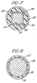
- Fig. 7 is a section similar to Fig. 3 with an alternate configuration for the cladding; and
- Fig. 8 is a view similar, to Fig. 3 illustrating an alternate embodiment wherein the solid rod has a circular cross-section.
- An infrared "optical fiber" which is a certain type of dielectric waveguide for guiding light waves designated generally as 10 is illustrated in Fig. 1. ' The
optical fiber cable 10 is shown attached at one end to a source of laser energy by means of aninterface 12 as shown in partial schematic in Fig. 1.Interface 12 designates the input end of theoptical fiber 10 and typically includes a lens (not shown) to match the incoming laser beam to the fiber 10- Fig. 1 also shows in schematic form ahandpiece 14, to permit manipulation of the laser output. One or more lenses may be included in thehandpiece 14 to provide collimation of the light output emanating from the optical fiber. Thefiber 10 may also end in any of a variety of end pieces examples of which are illustrated in Figs. 6a-6c and discussed below. - For purposes of this discussion, the
optical fiber 10 will refer to the entire cable betweeninterface 12 andhandpiece 14 and not merely to the waveguide portion. A detailed straight portion section of theoptical fiber 10 variously referred to as a "light pipe" or a flexible dielectric waveguide is shown in Fig. 2. In a preferred embodiment, theoptical fiber 10 is approximately a one meter long cylindrical cable. Thefiber 10 includes a flexibleouter sleeve 16 having good thermal conductivity as well as durability and is preferably fabricated of braided metal strands. On the inner surface of theouter sleeve 16 there is provided a concentriccladding material 18 having a relatively low index of refraction such as a plastic (e.g.., Teflon*) to thereby avoid scatter and field distortion of the transmitted light. The cylindrical region within thecladding material 18 is generally referred to as the core 20 in conventional optical fiber terminology. The materials comprising the core are selected for their high index of refraction relative to that of thecladding material 18 to afford total internal - *Registered Trademark of E. I. du Pont de Nemours & Co. reflection within core 20 of the transmitted laser light. The cladding material need not be IR transmissive as discussed in detail below.
- In the best mode of the present invention, the core 20 is all dielectric and includes a plurality of
solid rods 22 suspended in aliquid medium 24. The rods have a length x of approximately one centimeter and are fabricated from a compound having a very high rate of transmission of infrared energy at a wavelength of 10.6 micrometers, the wavelength characteristic of C02 lasers. One such material is the non-hygroscopic dielectric Irtran material zinc selenide (Irtran 4), which has a refractive index of approximately 2.4. ZnSe has total transmission loss at 10.6 µm of less than 0.1% per centimeter. There are a few materials that may be substituted for ZnSe, such as certain alkali halides, for example, polycrystalline thallium bromide and thallium bromoiodide (KRS-5). However, such halides require a vacuum tight environment because of their propensity to absorb moisture from the atmosphere which in turn deteriorates their IR transmissivity. A non-exhaustive list of IR transmissive materials for rods is set forth in Table 1.
- As shown in Fig. 3, the
solid rod 22 has a square cross-section approximately 1 mm x 1 mm with the diagonal dimension of the square being slightly less than the inside diameter of thecladding material 18. For ease of fabrication and to minimize the amount of liquid, an alternate cladding material configuration is used as shown in Fig. 7. -The cladding material 18' has a cylindrical exterior but a modified interior, conforming approximately to the square shape of therods 22. Alternatively, the rods have a circular cross-section as illustrated by rod 22' in Fig. 8. If a circular cross-section is used, the diameter of rod 22' is somewhat less than the inside diameter of thecladding material 18. - The
solid rods 22 are suspended in a liquiddielectric material 24, preferably carbon disulfide, CS2, which also has high transmissivity of-infrared light at a wavelength of 10.6 pm. Ether or germanium tetrachloride, GeCl4, may be substituted for CS2 as the liquid 24. Regardless of the choice of liquid, however, it must have a high rate of transmissivity of infrared energy at the prescribed wavelength and since thecable 10 is intended to be inserted into a patient's throat, it should preferably be relatively non-toxic. For use as an endoscope, the outer diameter, d, of thecable 10 is about 2 mm. - CS2 has a refractive index of approximately 1.6. In the ideal situation, the refractive index of the liquid 24 should be the same as the refractive index of the
solid rods 22. Otherwise, the propagation of the light wave through the dielectric interface between the two materials will result in a portion of the wave being reflected at the interface, thereby resulting in attenuation of the transmission. This problem is avoided by index matching between the liquid 24 and thesolid rods 22 by coating the solid rods with a material having a third index of refraction. The coating should be one-fourth the thickness of the wavelength of the transmitted wave and should have an index of refraction satisfying the following relationship:
- nc = index of refraction of the coating material;
- nl = index of refraction of the liquid; and
- nr = index of refraction of the rod.
- Thus, for a ZnSe rod having an index of refraction of approximately 2.4 disposed in liquid CS2 having an index of refraction of approximately 1.6, the index of refraction of the coating material should be in the range of 1.9 to 2.0. The coating may be applied to the ZnSe rods by the well-known vacuum deposition technique.
- The requirement for coating the
solid rods 22 is obviated by suspending therods 22 in a combination of two or more IR transmissive miscible liquids in such proportion that the index of refraction of the combination matches the refractive index of the material used for the rods. - Preferred choices for these liquids are carbon diselenide, CSe2, which has a refractive index of about 1.85, combined with carbon disulfide, CSz, which has a refractive index of about 1.63. A preferred choice for the rod material then would be an IR transmissive solid having a refractive index within the range for these miscible liquids, such as cesium iodide, CsI, which has a refractive index of about 1.72. Other combinations of IR transmissive miscible liquids will permit the choice of other rod materials. Since most IR transmissive liquids have refractive indices lower than that of ZnSe, the choice of solid rod materials utilizing this technique is limited. In general, most low loss IR transmissive materials are compounds having a relatively simple molecular configuration comprising heavy atoms thereby assuring fewer vibrational quantum numbers.
- Still another embodiment to the liquid/solid light pipe is one in which the liquid is not necessarily a liquid at room temperature, but has a low melting and/or softening temperature (<100°C). The melting or softening temperature is maintained by the use of heater elements around the light pipe. Of particular utility, for the 10.6 µm region is selenium, which is relatively non-toxic in elemental form and which has excellent IR transmission. As a further advantage, selenium's refractive index is very close to ZnSe's refractive index, so that uncoated ZnSe rods serve as the solid rod material. Finally, molten selenium is highly compatible chemically with ZnSe.
- As assembled, the
fiber 10 will include sufficient numbers of thesolid rods 22, as shown in Fig. 4, so that, on the average, the separation betweenadjacent rods 22 will be on the order of 0.01 to 0.05 millimeter. Such spacing, see Fig. 5, will permit a one meter length offiber 10 to be able to take a 90 degree bend. The total liquid path length is approximately that of the diameter d of the fiber, i.e., about 1-5 mm. Since the absorption coefficient a of the liquid is much greater than that of the rods, the amount of the liquid should be minimized as constrained by the 90° bending requirement. When ZnSe is used as the material for therods 22 and theliquid medium 24 is CS2, a one meter length offiber 10 even when deflected 90 degrees will transmit approximately 90 percent or more of the 10.6 µm infrared light it receives from a carbon dioxide laser. - For ease of fabrication and to mininize the volume of liquid, an alternate cladding material configuration as shown in Fig. 7 is used. The cladding material 18' has a cylindrical exterior but a modified interior, conforming approximately to the square shape of the
rods 22. - Any of several end pieces, such as
handpiece 14 or the embodiments illustrated in Figs. '6a, 6b, and 6c, may be conveniently attached in known fashion to the end of thelight pipe 10 for directing the output as needed. The handpiece 14' is illustrated in Fig. 6a includes acylindrical portion 26 whose outer diameter matches that of thelight pipe 10. Forward of thecylindrical portion 26 there is a tapered portion 23 from which the beam exists. A lens 30 is provided to collimate the exiting output laser beam. An alternative to handpiece 14' is a taperedhollow endpiece 32. Theendpiece 32 has a solid outer sleeve 34 which is connectable to the output end oflight pipe 10. Otherwise, theendpiece 32 is hollow with collimation achieved by its tapered configuration. The same configuration as that ofendpiece 32 is disclosed in Fig. 6c in which the endpiece 32' also has an outer sleeve 34' but is further provided with acore 36. Preferably the core is made of selenium glass; however, in general, any dielectric material will function provided its refractive index is greater than that of the outer sleeve 34'. - The decollimation experienced for a 90° bend is given by:

- where: d = fiber diameter;
- R = bend radius;
- αin = half angle of incident cone; and
- αout = half angle of emergent cone.
- For d « R, this reduces to:

- For total internal reflection, the critical incident angle is given by:

- where: nl = core index; and
- n2 = cladding index.
- Combining (3) and (4):

- For multiple bends, it follows that the half angle of the emergent cone is given by:


- Various cladding materials are possible for this light pipe.
- Defining:

- where: n2 = the complex refractive index of cladding;
- n2R = the real part of the refractive index of cladding;
- n2i = the imaginary part of the refractive index of cladding; and
- ni = the refractive index of core.
- From the previous derivation, it was shown that

- for: n = 2
- d = 1mm
- R = 10cm, equation (7) yields:

- Similarly, in order for the modal analysis to be valid in a dense dielectric guide, it can be shown that:


- For η1 = 1.6
- and η2 = 1.5 η2i « .1
- If η2i ≤ .01, a < 120 cm-1, where a = -dI/dz/I = absorption coefficient.
- Hence, a material which is essentially opaque in the IR can still be suitable as a cladding material. Certainly, most plastics have absorption coefficients less than 120 cm-1.
Claims (10)
Applications Claiming Priority (2)
| Application Number | Priority Date | Filing Date | Title |
|---|---|---|---|
| US42707682A | 1982-09-29 | 1982-09-29 | |
| US427076 | 1982-09-29 |
Publications (3)
| Publication Number | Publication Date |
|---|---|
| EP0105706A2 true EP0105706A2 (en) | 1984-04-18 |
| EP0105706A3 EP0105706A3 (en) | 1984-08-29 |
| EP0105706B1 EP0105706B1 (en) | 1987-08-19 |
Family
ID=23693393
Family Applications (1)
| Application Number | Title | Priority Date | Filing Date |
|---|---|---|---|
| EP83305818A Expired EP0105706B1 (en) | 1982-09-29 | 1983-09-28 | Flexible dielectric waveguide for high efficiency middle ir wavelength transmission |
Country Status (3)
| Country | Link |
|---|---|
| EP (1) | EP0105706B1 (en) |
| JP (1) | JPS5983105A (en) |
| DE (1) | DE3373149D1 (en) |
Cited By (16)
| Publication number | Priority date | Publication date | Assignee | Title |
|---|---|---|---|---|
| WO1985005262A1 (en) * | 1984-05-22 | 1985-12-05 | Surgical Laser Technologies Ohio, Inc. | Medical and surgical laser probe i |
| US4693244A (en) * | 1984-05-22 | 1987-09-15 | Surgical Laser Technologies, Inc. | Medical and surgical laser probe I |
| US4736743A (en) * | 1986-05-12 | 1988-04-12 | Surgical Laser Technology, Inc. | Vaporization contact laser probe |
| WO1989003202A2 (en) * | 1987-10-14 | 1989-04-20 | Schneider Richard T | Method and apparatus for laser emulsification |
| WO1989011261A1 (en) * | 1988-05-23 | 1989-11-30 | Schneider, Richard, T. | Medical laser device and method |
| US5074861A (en) * | 1988-05-23 | 1991-12-24 | Schneider Richard T | Medical laser device and method |
| US5207673A (en) * | 1989-06-09 | 1993-05-04 | Premier Laser Systems, Inc. | Fiber optic apparatus for use with medical lasers |
| US5267341A (en) * | 1991-10-30 | 1993-11-30 | Baxter International Inc. | Fluid catheter with aqueous fluid core and method of use |
| US5452395A (en) * | 1993-10-08 | 1995-09-19 | United States Surgical Corporation | Liquid light guide for endoscopic instrumentation |
| US5608834A (en) * | 1994-10-07 | 1997-03-04 | United States Surgical Corporation | Liquid Light guide |
| US5717807A (en) * | 1995-07-14 | 1998-02-10 | United States Surgical Corporation | Liquid light guide with improved sealing characteristics |
| WO1998025528A1 (en) * | 1996-12-10 | 1998-06-18 | Asah Medico A/S | An apparatus for cosmetic tissue treatment |
| DE19714080A1 (en) * | 1997-04-05 | 1998-10-15 | Rennebeck Klaus | Hollow micro-fibre application for optic conductor |
| US6190376B1 (en) | 1996-12-10 | 2001-02-20 | Asah Medico A/S | Apparatus for tissue treatment |
| WO2005026813A1 (en) * | 2003-09-10 | 2005-03-24 | Precision Optics Corporation | Acylindrical optical devices and method of manufacture |
| US7715105B2 (en) | 2003-09-10 | 2010-05-11 | Precision Optics Corporation | Acylindrical optical device |
Families Citing this family (1)
| Publication number | Priority date | Publication date | Assignee | Title |
|---|---|---|---|---|
| JP6387314B2 (en) * | 2015-03-19 | 2018-09-05 | 株式会社Nttドコモ | Wireless antenna, wireless communication system |
Citations (3)
| Publication number | Priority date | Publication date | Assignee | Title |
|---|---|---|---|---|
| US3414344A (en) * | 1964-01-18 | 1968-12-03 | Mukojima Michi | Flexible optical system for transmitting light or optical images |
| US3995934A (en) * | 1973-10-19 | 1976-12-07 | Nath Guenther | Flexible light guide |
| US4112028A (en) * | 1974-04-05 | 1978-09-05 | Environmental Research & Technology, Inc. | Light equalizer and method of making same |
-
1983
- 1983-09-28 DE DE8383305818T patent/DE3373149D1/en not_active Expired
- 1983-09-28 EP EP83305818A patent/EP0105706B1/en not_active Expired
- 1983-09-28 JP JP58180062A patent/JPS5983105A/en active Pending
Patent Citations (3)
| Publication number | Priority date | Publication date | Assignee | Title |
|---|---|---|---|---|
| US3414344A (en) * | 1964-01-18 | 1968-12-03 | Mukojima Michi | Flexible optical system for transmitting light or optical images |
| US3995934A (en) * | 1973-10-19 | 1976-12-07 | Nath Guenther | Flexible light guide |
| US4112028A (en) * | 1974-04-05 | 1978-09-05 | Environmental Research & Technology, Inc. | Light equalizer and method of making same |
Cited By (20)
| Publication number | Priority date | Publication date | Assignee | Title |
|---|---|---|---|---|
| WO1985005262A1 (en) * | 1984-05-22 | 1985-12-05 | Surgical Laser Technologies Ohio, Inc. | Medical and surgical laser probe i |
| US4693244A (en) * | 1984-05-22 | 1987-09-15 | Surgical Laser Technologies, Inc. | Medical and surgical laser probe I |
| US4736743A (en) * | 1986-05-12 | 1988-04-12 | Surgical Laser Technology, Inc. | Vaporization contact laser probe |
| WO1989003202A2 (en) * | 1987-10-14 | 1989-04-20 | Schneider Richard T | Method and apparatus for laser emulsification |
| WO1989003202A3 (en) * | 1987-10-14 | 1989-08-10 | Richard T Schneider | Method and apparatus for laser emulsification |
| WO1989011261A1 (en) * | 1988-05-23 | 1989-11-30 | Schneider, Richard, T. | Medical laser device and method |
| US5074861A (en) * | 1988-05-23 | 1991-12-24 | Schneider Richard T | Medical laser device and method |
| US5207673A (en) * | 1989-06-09 | 1993-05-04 | Premier Laser Systems, Inc. | Fiber optic apparatus for use with medical lasers |
| US5267341A (en) * | 1991-10-30 | 1993-11-30 | Baxter International Inc. | Fluid catheter with aqueous fluid core and method of use |
| US5452395A (en) * | 1993-10-08 | 1995-09-19 | United States Surgical Corporation | Liquid light guide for endoscopic instrumentation |
| US5608834A (en) * | 1994-10-07 | 1997-03-04 | United States Surgical Corporation | Liquid Light guide |
| US5717807A (en) * | 1995-07-14 | 1998-02-10 | United States Surgical Corporation | Liquid light guide with improved sealing characteristics |
| WO1998025528A1 (en) * | 1996-12-10 | 1998-06-18 | Asah Medico A/S | An apparatus for cosmetic tissue treatment |
| US6190376B1 (en) | 1996-12-10 | 2001-02-20 | Asah Medico A/S | Apparatus for tissue treatment |
| US6533776B2 (en) | 1996-12-10 | 2003-03-18 | Asah Medico A/S | Apparatus for tissue treatment |
| DE19714080A1 (en) * | 1997-04-05 | 1998-10-15 | Rennebeck Klaus | Hollow micro-fibre application for optic conductor |
| DE19714080B4 (en) * | 1997-04-05 | 2005-09-08 | Rennebeck, Klaus, Dr. | Use of micro hollow fibers |
| WO2005026813A1 (en) * | 2003-09-10 | 2005-03-24 | Precision Optics Corporation | Acylindrical optical devices and method of manufacture |
| US7116486B2 (en) | 2003-09-10 | 2006-10-03 | Precision Optics Corporation, Inc. | Cylindrical optical devices and method of manufacture |
| US7715105B2 (en) | 2003-09-10 | 2010-05-11 | Precision Optics Corporation | Acylindrical optical device |
Also Published As
| Publication number | Publication date |
|---|---|
| DE3373149D1 (en) | 1987-09-24 |
| JPS5983105A (en) | 1984-05-14 |
| EP0105706B1 (en) | 1987-08-19 |
| EP0105706A3 (en) | 1984-08-29 |
Similar Documents
| Publication | Publication Date | Title |
|---|---|---|
| EP0105706B1 (en) | Flexible dielectric waveguide for high efficiency middle ir wavelength transmission | |
| US4045119A (en) | Flexible laser waveguide | |
| US5495541A (en) | Optical delivery device with high numerical aperture curved waveguide | |
| US5567471A (en) | Coherent, flexible, coated-bore hollow-fiber waveguide, and method of making same | |
| US5815627A (en) | Co-axial hollow core waveguide | |
| US3920980A (en) | Flexible light guide | |
| US5707368A (en) | Contact tip for laser surgery | |
| EP0307487B1 (en) | Collimator lens for optical fiber | |
| EP0198603A1 (en) | Hollow waveguides having disparate dielectric overcoatings | |
| US3966300A (en) | Light conducting fibers of quartz glass | |
| US4828354A (en) | Infrared fiber | |
| US4583821A (en) | Infrared fibers | |
| Kozodoy et al. | Small-bore hollow waveguides for delivery of 3-μm laser radiation | |
| EP0234233B1 (en) | High power optical fiber | |
| Harrington et al. | Transmission properties of hollow glass waveguides for the delivery of CO/sub 2/surgical laser power | |
| Croitoru et al. | Use of metallic and dielectric films for hollow fibers | |
| Arai et al. | Carbon monoxide laser power delivery with an As 2 S 3 infrared glass fiber | |
| Hongo et al. | Excitation dependent losses and temperature increase in various hollow waveguides at 10.6 μm | |
| US5625638A (en) | Sealed crystalline windows for hollow laser fibers | |
| US4738497A (en) | Antireflection film | |
| Harrington | Co-axial hollow core waveguide, US Patent 5,815,627 | |
| Behler et al. | Flexible hollow-core waveguides for CO2 lasers: potential and limitations as beam guiding systems for medical applications | |
| JPS61188507A (en) | Optical waveguide | |
| Ben-David et al. | Fibers and Waveguides for Medical Applications | |
| Boucher et al. | New developments and applications of MIR-fibres in the 4-15 mum spectral range |
Legal Events
| Date | Code | Title | Description |
|---|---|---|---|
| PUAI | Public reference made under article 153(3) epc to a published international application that has entered the european phase |
Free format text: ORIGINAL CODE: 0009012 |
|
| AK | Designated contracting states |
Designated state(s): DE FR GB |
|
| PUAL | Search report despatched |
Free format text: ORIGINAL CODE: 0009013 |
|
| AK | Designated contracting states |
Designated state(s): DE FR GB |
|
| 17P | Request for examination filed |
Effective date: 19841231 |
|
| 17Q | First examination report despatched |
Effective date: 19860522 |
|
| GRAA | (expected) grant |
Free format text: ORIGINAL CODE: 0009210 |
|
| AK | Designated contracting states |
Kind code of ref document: B1 Designated state(s): DE FR GB |
|
| REF | Corresponds to: |
Ref document number: 3373149 Country of ref document: DE Date of ref document: 19870924 |
|
| ET | Fr: translation filed | ||
| PLBE | No opposition filed within time limit |
Free format text: ORIGINAL CODE: 0009261 |
|
| STAA | Information on the status of an ep patent application or granted ep patent |
Free format text: STATUS: NO OPPOSITION FILED WITHIN TIME LIMIT |
|
| 26N | No opposition filed | ||
| PG25 | Lapsed in a contracting state [announced via postgrant information from national office to epo] |
Ref country code: GB Effective date: 19880928 |
|
| PG25 | Lapsed in a contracting state [announced via postgrant information from national office to epo] |
Ref country code: FR Free format text: LAPSE BECAUSE OF NON-PAYMENT OF DUE FEES Effective date: 19890531 |
|
| GBPC | Gb: european patent ceased through non-payment of renewal fee | ||
| PG25 | Lapsed in a contracting state [announced via postgrant information from national office to epo] |
Ref country code: DE Effective date: 19890601 |
|
| REG | Reference to a national code |
Ref country code: FR Ref legal event code: ST |